EP1959317A1 - Mechanismus zur umschaltbaren Übertragung - Google Patents
Mechanismus zur umschaltbaren Übertragung Download PDFInfo
- Publication number
- EP1959317A1 EP1959317A1 EP07003114A EP07003114A EP1959317A1 EP 1959317 A1 EP1959317 A1 EP 1959317A1 EP 07003114 A EP07003114 A EP 07003114A EP 07003114 A EP07003114 A EP 07003114A EP 1959317 A1 EP1959317 A1 EP 1959317A1
- Authority
- EP
- European Patent Office
- Prior art keywords
- wheel
- control
- transmission
- movement
- pawl
- Prior art date
- Legal status (The legal status is an assumption and is not a legal conclusion. Google has not performed a legal analysis and makes no representation as to the accuracy of the status listed.)
- Granted
Links
Images


Classifications
-
- G—PHYSICS
- G04—HOROLOGY
- G04B—MECHANICALLY-DRIVEN CLOCKS OR WATCHES; MECHANICAL PARTS OF CLOCKS OR WATCHES IN GENERAL; TIME PIECES USING THE POSITION OF THE SUN, MOON OR STARS
- G04B19/00—Indicating the time by visual means
- G04B19/02—Back-gearing arrangements between gear train and hands
-
- G—PHYSICS
- G04—HOROLOGY
- G04B—MECHANICALLY-DRIVEN CLOCKS OR WATCHES; MECHANICAL PARTS OF CLOCKS OR WATCHES IN GENERAL; TIME PIECES USING THE POSITION OF THE SUN, MOON OR STARS
- G04B19/00—Indicating the time by visual means
- G04B19/04—Hands; Discs with a single mark or the like
- G04B19/048—Hands; Discs with a single mark or the like having the possibility of indicating on more than one scale, e.g. hands with variable length which work on different scales
-
- G—PHYSICS
- G04—HOROLOGY
- G04F—TIME-INTERVAL MEASURING
- G04F7/00—Apparatus for measuring unknown time intervals by non-electric means
- G04F7/04—Apparatus for measuring unknown time intervals by non-electric means using a mechanical oscillator
- G04F7/08—Watches or clocks with stop devices, e.g. chronograph
- G04F7/0866—Special arrangements
Definitions
- the present invention relates to a switchable transmission mechanism intended to be integrated in a watch movement and comprising a transmission pinion rotated by a first mobile of said movement so as to represent a first piece of information to be displayed, as well as a watch movement and a watch with such a mechanism.
- the present invention seeks to propose a simple and effective solution for displaying several data at the same time. with the aid of a minimum number of indicating means, in particular needles,
- the switchable transmission mechanism is distinguished for this purpose by the features listed in claim 1 and / or the dependent claims, in particular by the fact that it comprises an element carrying a first rattrapante core, this element being mounted idly on the transmission pinion of the mechanism and being rotated by said first - or by a second mobile of said movement so as to represent a second piece of information to be displayed, a second split-second core being fixed on said transmission pinion, a transmission wheel being mounted idle about said transmission gear and carrying a first - respectively a second hammer preloaded by a first - respectively a second biasing spring against said first - respectively second core, a wheel switching device being rotatably mounted on the periphery of the transmission wheel and carrying a first - respectively a second cam acting on said first - respectively second hammer so as to alternately remove the contact between the first hammer and the first core respectively the second hammer and the second core in order to switch the position of said transmission wheel according to the first - respectively the second information to
- the display means can be switched between at least two states corresponding to this information to the using the mechanism according to the present invention.
- the user is not disturbed in reading the information displayed by other indication elements.
- the mechanism provided is simple and effective.
- the change in the display can be done at any time according to the desire of the user.
- the figure 1 shows a perspective view of a chronograph movement having a switchable transmission mechanism according to the present invention, the dial and other elements being removed to allow the view of certain parts of the movement described in more detail below.
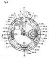
- the figure 2 is a top view of the chronograph shown in the figure 1 while at the same time illustrating the control mechanism cooperating with the integrated switching mechanism in a switchable transmission mechanism according to the present invention.
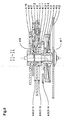
- the figure 3 is a cross-section along the line II indicated in the figure 2 .
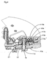
- the figure 4 represents an enlargement of this section, seen in perspective, showing in particular the mechanism for transmitting the mobile of the seconds.
- the figure 5 is a view from above of said transmission mechanism of the mobile seconds.
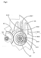
- the figure 6 shows a perspective view of the transmission mechanism of the hours mobile isolated from the other components of the chronograph movement.
- the figure 7 represents a top view on the mechanism of the figure 6 .
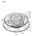
- the figure 8 is a cross section of said mechanism along the line II-II in the figure 7 .
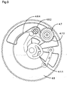
- the figure 9 is a top view showing in greater detail some parts of the switching mechanism integrated in a transmission mechanism according to the present invention.
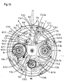
- the figure 10 shows a top view of the chronograph, with some bridges, wheels and other elements removed to illustrate the chronograph control mechanism.
- the figure 11 is a top view of a detail of the figure 2 showing more precisely the mechanism for indicating the mode of operation of the transmission mechanism.
- this embodiment serves mainly to illustrate in detail the principle of a switchable transmission mechanism according to the present invention.
- This mechanism is however not limited to the case of its application in a chronograph and can perfectly be used in the context of other horological applications such as the indication of the date, the indication of time in another time zone, the indication of the power reserve, indication of the diving depth for a diving watch, etc., as will be explained in more detail in the following description.
- the dial and other elements of the upper part of the chronograph are not shown to allow the view of certain parts within the movement which will be described in more detail below.
- the figure 3 shows the entire chronograph cut transversely along the line I-1 indicated in the figure 2 .
- the chronograph represented Figures 1 to 3 respectively a watch having a transmission mechanism according to the The present invention is equipped with a driving member 1 and a regulating member 2.
- the driving member 1 may consist of a barrel spring and the regulating member 2 in a rocker cooperating with a corresponding escapement as is known in FIG. the context of mechanical watches, particularly complicated watches, and illustrated in part in the accompanying figures. It is nevertheless entirely possible to use, for example, an electronic energy source and a quartz respectively an electronic-mechanical combination in place of these organs. Because these members 1, 2 do not form part of the invention, they will not be described here in more detail.
- the force from the drive member 1 is transmitted to a display train 3, the wheel 3 comprising a single set of indicating means, preferably a single set of needles.
- this force is first transmitted, as is apparent from the figure 3 , at a pinion of average 3.1.
- An average wheel 3.2 attached to said pinion 3.1 then transmits this force to a switchable transmission mechanism 4 according to the present invention, in particular to the transmission mechanism of the seconds 4a, meshing with a transmission pinion seconds 4.1a.
- This pinion 4.1a carries a base wheel seconds 4.2a located in connection with the exhaust respectively generally with the regulating member 2 to determine the frequency of rotation of this mobile.
- said second transmission pinion 4.1a still carries a second transmission wheel 4.6a meshing with a second indication wheel 3.3a.
- This wheel 3.3a is rotatably mounted around a fixed tenon 3.5, which is preferably in the center of the watch movement and is attached to the seconds tube 3.4a carrying a seconds hand not shown in the figures.
- a 3.4b minute tube and a 3.4c hours tube are mounted, in the case shown in the figures, coaxially and rotatively around the seconds tube 3.4a, the tubes 3.4b, 3.4c each carrying a wheel for indicating the minutes 3.3b respectively a indication wheel hours 3.3c and a minute hand respectively one hour hand.
- any other positioning of the Murant display is possible, for example an eccentric configuration.
- the chronograph comprises, next to the transmission mechanism of the seconds 4a, another mechanism for transmission of the minutes 4b and a transmission mechanism of the hours 4c.
- These mechanisms 4b, 4c are, like the transmission mechanism of the seconds 4a, arranged laterally around the display mobile, as illustrated for example by the figures 1 and 2 , so that their transmission wheel minutes 4.6b respectively - hours 4.6c can mesh with said indication wheels minutes 3.3b respectively - hours 3.3c of the mobile display, similar to the gear described ci above the seconds transmission wheel 4.6a with the seconds indicating wheel 3.3a.
- the three transmission mechanisms 4a, 4b, 4c that includes the chronograph illustrated at Figures 1 to 4 have a nearly identical structure, and the fact that this device comprises a transmission mechanism 4 according to the present invention to three units depends solely on the application in question. There could also be only for example a second transmission mechanism and a minute transmission mechanism. For some other applications, one such mechanism could be sufficient, as will become clearer in the following description. As a result, the detailed structure of such a transmission mechanism 4 will be explained in the following by way of example to using the transmission mechanism of hours 4c illustrated in Figures 1 to 3 . In the following, the suffixes a, b, e as well as the precisions in the nomenclature if it is the motive of the seconds, minutes or hours will not be because of the aforementioned reasons normally more used, at least regarding the transmission mechanism.
- the set of single indication means mentioned in the introduction is formed in the application present by the three hands of seconds, minutes and hours carried respectively by the tubes of the seconds 3.4. a, minutes 3.4b and 3.4c hours of the mobile display.
- this game could also consist for example only in a single needle or other type of indication means, such as a display disc.
- such a mechanism 4 comprises firstly a transmission gear 4.1 constituting the axis of rotation of the mechanism and carrying said base wheel 4.2 which in the example of the transmission mechanism of the seconds cooperates with the exhaust.
- the transmission pinion 4.1 is then normally driven in one way or another by the driving member 1 and the regulating member 2 of the watch movement so as to transmit to the display gear 3 the information concerning a unit of the current time, for example seconds, minutes or hours, except in the case of particular applications which will be mentioned later in the text.
- a clutch means comprising, on the one hand, a clutch disc 4.3 mounted crazy around the pinion of transmission 4.1.
- a stop ring 4.5 integral around the pinion 4.1 which compresses, in the axial direction of the pinion 4.1, a friction spring 4.4 placed between the ring 4.5 and said clutch plate 4.3. Because this 4.3 disc can not not be moved axially, it then normally follows the rotation of the transmission pinion 4.1 because of the friction clutch made by the friction spring 4.4.
- the clutch disc 4.3 can also be locked against any rotation, for example by means of a clamp surrounding and co-operating, if it is closed, with an outer groove that includes the outer periphery of the disc 4.3 .
- the pinion 4.1 continues its rotation while the disc 4.3 is stopped.
- the control mechanism for said clamp will be described elsewhere in the following.
- the clutch disk 4.3 has on its upper side a reset core 4.3.2 and a first split core 4.3.1 serving in this application as the heart of timed time and lying on the lower side of said transmission wheel 4.6 mentioned above. These two cores are for example fixed to the disc 4.3 with the aid of a pin, so that the cores are rotated with the clutch disc 4.3.
- a second split core 4.1.1 serving in this application as the heart of the current time is on the upper side of the transmission wheel 4.6.
- This second split core 4.1.1 is fixed to the transmission sprocket 4.1 and therefore always follows its rotation, unlike the first split core 4.3.1 which can be disengaged using the clamp mentioned above.
- a transmission unit including in particular said transmission wheel 4.6 which is, in the application of a chronograph as shown in the figures, engaged with one of the indication wheels 3.3.
- This transmission wheel 4.6 is also madly mounted around the transmission sprocket 4.1 and carries, on its lower or upper sides respectively, a first hammer 4.6.1 respectively a second hammer 4.6.2 mounted pivotally on the transmission wheel 4.6 and serving of probes on said first - 4.3.1 respectively second hearts 4.1.9.
- This configuration is illustrated at the cut of the figure 8 and at the figure 9 using a view from above of the transmission wheel 4.6 with the second split core 4.1.1 and the second hammer 4.6.2 which is prestressed against the core 4.1.1 via a second spring prestress 4.6.4 fixed to the transmission wheel 4.6.
- the first hammer 4.6.1 is prestressed analogically by a first biasing spring 4.6.3 against the first spacer core 4.3.1,
- a switching mechanism is mounted on the transmission wheel 4.6 to ensure that only one hammer at a time is in contact with one of the cores 4.3.1, 4.1.1.
- This switching mechanism comprises a switching wheel 4.7 rotatably mounted about an axis of rotation on the periphery of the transmission wheel 4.6, this axis being parallel to the transmission pinion 4.1.
- the switching wheel 4.7 comprises a first cam 4.7.1 and a second cam 4.7.2 located on the lower or upper side respectively of the transmission wheel 4.6, in the same plane as the first hammer 4.6.1 respectively the second hammer 4.6 .2 mentioned above.
- the two cams 4.7.1, 4.7.2 may have, apart from other alternative forms, substantially the shape of a straight bar, this being, fixed to.
- FIG 9 This configuration is illustrated in figure 9 .
- a rotation 90 ° of the switching wheel 4.7 causes, on the one hand, that the first cam 4.7.1 no longer bears against the first hammer 4.6.1, the latter being thereby prestressed by its biasing spring 4.6. 3 against the first split-second core 4.3.1, as well as, on the other hand, that one end of the second cam 4.7.2 bears against the second hammer 4.6.2 thus removing its contact with the second split-core 4.6. 2.
- Another rotation of 90 ° reproduces the constellation of before, this time the other end of the first cam 4.7.1 pressing against the first hammer 4.6.1, and so on.
- the switchable transmission mechanism further comprises an intermediate control wheel 4.9 fixed on a control post 4.8 which is mounted idly around the transmission pinion 4.1, on the upper side of the transmission wheel 4.6.
- the intermediate control wheel 4.9 is engaged with the switching wheel 4.7 and can cause it to rotate.
- a control wheel 4.10 is fixed on the control post 4.8 and allows, via a control mechanism described later in the description, that the double wheel formed of the control wheel 4.10 and the intermediate control wheel 4.9 fixed on the control pin 4.8 can drive the switching wheel 4.7 to switch the position of the latter relative to the transmission wheel 4.6, thus switching the hammers 4.3.1, 4.6.2 against their core 4.3.1, 4.1.1 corresponding
- This relative position of the switching wheel 4.7 can also be protected against unintentional rotation for example by means of an elastic locking element or any other suitable means, for example d a jumper fixed on a bridge and resting against the control wheel 4.10 or even a jumper fixed on the transmission wheel and bearing against the switching wheel 4.7
- the pinion of transmission is always driven, in the application shown in the figures, by the watch movement, its rotation being transmitted by the transmission wheel 4.6 to the indication wheel 3.3 if the second hammer 4.6.2 is in contact with the second core 4.1 .1, the heart of the current time, while there is no contact between the first hammer 4.6.1 and the first core 4.3.1.
- the current time is displayed by the single set of needles.
- the position of the switching wheel 4.7 is changed by a rotation of 90 °, the contact between the second hammer 4.6.2 and the second core 4.1.1 is removed, while the first hammer 4.6.1 taps, under the action of the prestressing spring 4.6.3, on the first split-second core 4.3.1, the heart of the timed time.
- the transmission wheel then rotates until the hammer 4.6.1 found its stable position on the core 4.3.1, which corresponds to the time measured.
- the single set of hands displays the timed time because this same operation is performed simultaneously on the three mobiles of the seconds 4a, minutes 4b and hours 4c.
- a transmission mechanism 4 according to the present invention in a chronograph involves several consequences.
- such a chronograph comprises three such mechanisms in order to be able to display the seconds, minutes and hours of the timed time, these three mechanisms being, as already mentioned above, placed laterally around the mobile display, allowing thus easily the gearing of each transmission wheel 4a, 4b, 4c in the corresponding indication wheel 3.3a, 3.3b, 3.3c.
- the clutch means has a structure specifically adapted to this application.
- the clutch means comprises, apart from the first heart of the second timer 4.3.1 for the indication of the timed time, another heart, the resetting heart 4.3.2. This is placed in such a way on the clutch plate 4.3 that a corresponding reset hammer 4.3.3 fixed for example on the chronograph frame can, once it is released, tap on the periphery of said core 4.3.2 to drive the clutch disc 4.3 in rotation until the corresponding needle is returned to the 12 o'clock position. It is clear in this context that in all the aforementioned actions involving a rotation of the clutch disk 4.3, said clamp surrounding this disk is spaced simultaneously to release it, which will be described later in the context of the mechanism of chronograph control.
- the switching of the transmission mechanism according to the present invention is carried out, by means of the switching wheel 4.7 and the two corresponding cams 4.7.1, 4.7.2, using two cores 4.3.1, 4.1.1 fixed on elements each representing a quantity to display and two hammers 4.6.1, 4.6.2 corresponding fixed on the 4.6 transmission wheel including a heart palp whose corresponding information should be displayed. It is then possible to display almost any information normally available in a watch using a mechanism according to the present invention by connecting an element carrying a heart corresponding to the mobile representing the desired information.
- the clutch disc 4.3 can be replaced by a date wheel madly mounted around the transmission pinion 4.1 and driven in a known manner by a mobile of calendar.
- the indication of time in another time zone, sidereal time, moon phase or even dive depth is still to be given as an example.
- the element respectively the wheel bearing the heart corresponding to this information should be driven for example by the depth detector as is also known to those skilled in the art of watchmaking.
- Different combinations of this information are imaginable that do not necessarily imply the indication of the current time by the single set of needles see by the single needle, for example the indication of either the date or the depth of diving as a function of the position of the switching wheel. 4.7 relating to the transmission wheel 4.6. It is obvious that the dial of the watch will be arranged correspondingly.
- the watch in which the chronograph illustrated in the figures should be integrated preferably has two pushers 6, 7 and a crown with a third integrated push rod 8. These elements are mounted in the watch case in a conventional manner and do not not appear in the figures, however figure 10 shows the elements on which these pushers act.
- a first start-stop pushbutton 6 of the chronograph acts on a start-stop corrector 6.1 which can be moved axially towards the center of the movement by being guided by four pins placed laterally around it. If this corrector 6.1 is moved inwards, it pivots a first lever 6.2 pivotally mounted around a pin not shown, the outwardly directed end of the chronograph of the first lever 6.2 being engaged in a triangular notch of the corrector 6.1. At the same time, the first lever 6.2 carries a pin with which is engaged a second lever 6.3 prestressed by a corresponding biasing spring 6.4 so as to push the first lever 6.2 and thus the start-stop corrector 6.1 respectively all the start button -stop 6 outward after manual operation.
- Such a first actuation causes, through the inwardly directed end of the chronograph of the first lever 6.2, a clockwise rotation of a shuttle 6.5 around its center of rotation 6.5.1. since this end of the first lever 6.2 cooperates with a first plane located in a lateral notch 6.5.2 of the shuttle 6.5.
- the shuttle 6.5 is then indexed in this non-illustrated position by means of a shuttle jumper spring 6.6 cooperating with one of two positioning notches formed on the shuttle 6.5; the other positioning notch indexes the shuttle in cooperation with said spring jumper shuttle 6.6 in its initial position illustrated at figure 10 .
- the clockwise rotation of the shuttle 6.5 causes a lever referred to in the octopus suite 6.7 and pivotally mounted about the axis of the chronograph display movable so as to turn it counterclockwise.
- this octopus 6.7 has an inclined plane 6.7.1 on which acts a pin 6.5.3 mounted on the shuttle 6.5, the octopus being preloaded by a spring arm 6.7.2 of the octopus against this pin 6.5.3.
- the octopus 6.7 is then pushed against the pin 6.5.3 of the shuttle 6.5, a rotation in the clockwise direction of the shuttle thus resulting by the action of its pin 6.5.3 on the inclined plane 6.7.1 of the octopus 6.7 in a counter-clockwise rotation of the octopus 6.7, which then takes its second stable position, the starting position of the chronograph.
- the name of these positions is due to the fact that the octopus 6.7 still has three arms 6.7.3, 6.7.4, 6.7.5 each of which is engaged with a pin 6.8.2 placed on a clamp 6.8 already mentioned above.
- each of the three clamps 6.8a, 6.8b, 6.8c for blocking, in its tight state, or to release, in its separated state, the corresponding clutch disk 4.3 of the transmission mechanism of the seconds 4a, - minutes 4b and 4c hours.
- each clamp 6.8 can indeed slide forward and back by being guided by two pins fixed to the chronograph frame and passing through a guide housing in a central arm 6.8.1 of the clamp 6.8.
- each gripper 6.8 In the stop position of the chronograph described above, each gripper 6.8 is thus in its forward position with respect to the corresponding clutch disc 4.3, the front ends 6.8.3 of the gripper 6.8 surrounding this disc 4.3 being tight to the outside.
- a second action on the first pusher 6 simply causes, through an action of said end facing inward of the chronograph of the first lever 6.2 on a second plane located in the lateral notch 6.5.2 of the shuttle 6.5, a counter-clockwise rotation of the shuttle 6.5 around its center of rotation 6.5.1 respectively a rotation of the octopus 6.7 in the clockwise direction, due to the action of its spring arm 6.7.2 in that Sens.
- Each clamp 6.8 is then returned to its forward position and the clutch discs are again blocked, which stops the chronograph in its measurement of time timed.
- a second reset pushbutton 7 of the chronograph acts on a reset corrector 7.1 which can be moved axially towards the center of the movement. At its end facing the inside of the chronograph it has an inclined plane which cooperates with a corresponding inclined plane of a fifth arm 6.7.6 of the octopus 6.7 so as to turn it in the anti-clockwise direction.
- clutch disks 4.3 are then released as described above, but this c is this action is initiated by the second pusher 7.
- the octopus returns to its original position. initial position and the 4.3 disks are blocked again.
- said reset equalizer 7.1 carries a pin 7.1.1 engaged in an opening formed in one end of a correction lever 7.2 which is pivotally mounted around a screw fixed on a chronograph bridge.
- the other end of this correction lever 7.2 carries a pin 7.2.1 which is normally, that is to say as long as the second pusher 7 is not actuated manually, engaged in a locking notch 7.3.1 in a reset ring 7.3 so as to block the latter center any rotation in the counterclockwise direction, in which sense it is prestressed by means of a prestressing spring 7.4 pressing on a corresponding pin placed on this ring 7.3.
- This reset ring 7.3 further comprises, on its inner circumference, three control notches 7.3.2 each located in front of a reset hammer 7.5.
- Each reset hammer 7.5a, 7.5b, 7.5c is pivotally mounted on a chronograph bridge and is in the same work plane as the reset core 4.3.2a, 4.3.2b, 4.3. 2c corresponding mentioned above in the description.
- each hammer 7.5 is prestressed against the corresponding resetting core 4.3.2 by means of a prestressing spring 7.6 pressing a corresponding pin fixed on each hammer.
- the hammers 7.5 can not come into contact with the corresponding reset core 4.3.2 as long as the reset ring 7.3 is in its initial position, that is to say if the second pushbutton is not pushed, because an eccentric 7.5.1 mounted on each hammer 7.5 is in contact with the lower circumference of the ring 7.3 and prevents their actuation.
- the eccentrics 7.5.1 are released because they are located opposite said control notches 7.3.2 on the ring 7.3 and the hammers tap on the outer periphery of the corresponding reset heart 4.3.2, rotating them to their position-stable, which corresponds to the position of 12h needles.
- This reset action is possible because the clutch disks 4.3 carrying the reset cores 4.3.2 were released simultaneously as described above.
- the eccentrics 7.5.1 can be rotated correspondingly.
- the reset ring 7.3 also has a return notch 7.3.3 on its inner circumference, in which a return lever 7.7 can engage to return the ring to its initial position, once the second pushbutton 7 has been pushed.
- the return lever 7.7 is mounted on the shuttle 6.5 and comes into contact with said return notch 7.3.3 of the ring 7.3, in the case where the latter is in the rotated position after actuation of the second reset pushbutton 7, if the first start-stop pushbutton of the chronograph is pushed into its start function as described above, said shuttle 6.5 is then driven in the clockwise direction, with the result that the return lever brings the reset ring back to zero in its initial position, against the prestressing spring 7.4.
- the two pushers 6, 7 can then control the known functions of a chronograph.
- the control mechanism for switching the state of the transmission mechanism cooperates with the switching mechanism integrated in a switchable transmission mechanism according to the present invention, in particular with the switching wheel 4.7 and the control wheel 4.10 mentioned above.
- a watch equipped with such a mechanism normally comprises a non-illustrated crown coupled to a winding stem to perform conventional functions such as winding and setting the time of the indication means.
- a third switching pusher 8 is preferably arranged coaxially with said winding stem; obviously, it could be placed elsewhere.
- This third pusher 8 is connected to a switching element 8.1 which can move axially and which in turn makes it possible to pivot, via a pin passing through these two parts, a switching lever 8.2 carrying on its working end an actuating pin 8.2.1.
- This pin 8.2.1 can engage, when the third pusher 8 is manually operated, on an inclined plane formed in an operating notch 8.3.1 on the outer circumference of a first control ring 8.3, so as to this ring rotates around an angle corresponding to the length of said inclined plane in the counter-clockwise direction.
- the first ring 8.3 also comprises an arm 8.3.2 with a substantially Z-shaped spring 8.3.3 which bears on a pin 8.4.2 fastened to an arm 8.4.1 of a second control ring 8.4 placed, preferably, below the first control ring 8.3, as illustrated for example in FIG. figure 2 .
- a manual actuation of the third pusher 8 then causes, through the rotation of the first control ring 8.3, also the rotation in the counter-clockwise direction of the second control ring 8.4, the latter being limited in its rotation by a limiting eccentric 8.5 fixed. on a bridge of the chronograph and on which taps a front plane of said arm 8.4.1 of the second ring 8.4.
- this second ring further comprises three ratchets 8.4.3a, 8.4.3b, 8.4.3c each placed in front of a transmission mobile 4a, 4b, 4c with which it cooperates.
- each pawl 8.4.3 is located in the same work plane as the control wheel 4.10 of the corresponding transmission wheel and is prestressed against this wheel 4.10 by a control preloading spring 8.3.4 forming for example an integral part of the first control ring 8.3.
- Each pawl 8.4.3 does not press on the corresponding wheel 4.10 as long as the third pusher 8 is not actuated because the first control ring 8.3 still has three retaining springs 8.3.5 which are normally engaged each in a notch at the end located, seen in the anti-clockwise direction, behind each pawl 8.4.3 so as to prevent the pawl from pressing the wheel 4.10.
- a manual actuation of the third pusher 8 then causes, as described above, the rotation of the first-8.3 and the second control ring 8.4 in the counter-clockwise direction, the movement of the second ring 8.4 being limited, if the manual force on the third pusher is sufficient, by said limiter eccentric 8.5, while the rotation of the first ring 8.3 continues until the spring 8.3.3 on its arm 8.3.2 is completely compressed by the support against the pin 8.4.2 attached to the 8.4.1 arm of the second control ring 8.4. Due to this counterclockwise relative rotation of the first ring 8.3 relative to the second ring 8.4, the retaining springs 8.3.5 release the pawls 8.4.3 so that they support, under the effect of their control preloading springs 8.3.4, on the corresponding wheel 4.10.
- each pawl 8.4.3 which is at this moment in engagement with the corresponding control wheel 4.10, drives this wheel in rotation and thus makes it possible, by means of the intermediate control wheel 4.9, to turn the wheel of switching 4.7 corresponding to a 90 ° angle in order to switch the position of the cams 4.7.1, 4.7.2.
- This control mechanism thus makes it possible to perform the switching in the transmission mechanism according to the present invention.
- each pawl 8.4.3 also comprises an eccentric 8.3.4.1 with a corresponding pin which enters a recess arranged in the bridge. for example, below the two rings 8.3, 8.4.
- This recess has a shape adapted to guide, at the end of the return movement stroke of the two rings 8.3, 8.4, the ratchets 8.3.4 in their initial position in which they are again taken by the springs of retained 8.3.5, that is to say that their contact with the control wheel 4.10 is again removed.
- the device also comprises a mechanism for indicating the operating mode of the transmission mechanism.
- the first control ring 8.3 further comprises a needle spring 8.3.6 located in a longitudinal recess on the ring 8.3, this recess having an open side oriented towards the inside of the ring.
- a lateral flank is formed on the ring 8.3, each lateral flank being preferably slightly rounded, the curvature being so as to form a lateral recess to allow laterally pivoting the needle spring 8.3.6 and guiding its movement.
- the longitudinal recess formed in the control ring 8.3 further comprises, at its front portion located towards the opening, a shape adapted to limit, through its inner walls, the lateral movement of the needle spring. 8.3.6, which can lead to arrange this lateral recess substantially shaped keyhole.
- the needle spring 8.3.6 comprises a first part forming an elastic arm and housed in this recess, one end of this first part being fixed to the bottom of the closed side of the longitudinal recess on the ring 8.3 and its longitudinal axis being substantially parallel to the longitudinal axis of this recess.
- This elastic arm respectively all the needle spring 8.3.6 may preferably be formed integrally with said ring 8.3.
- the needle spring 8.3.6 has a second part forming a switch-needle which is formed of a piece respectively fixed on the other end of said elastic arm.
- this second part comprises, at the height of the lateral flanks on said longitudinal recess, two substantially triangular lateral wings each having a rear portion of a shape corresponding to the shape of said lateral flanks, for example rounded, thus allowing the 8.3.6 spring-spring to perform a lateral movement, which is possible thanks to its elastic arm mentioned above, and to be guided by said lateral flanks on the ring 8.3.
- the second part of the needle spring 8.3.6 comprises on its free end a tip which is preferably rounded and which cooperates with one or the other inclined plane situated on a substantially triangular arm 8.7 .1 which is fixed coaxially to the axis of rotation on an indicating lever 8.7 pivotally mounted on a chronograph bridge.
- the triangular arm 8.7.1 is oriented so that its tip is substantially on the longitudinal axis of the needle spring 8.3.6.
- this lever 8.7 comprises a first toothed sector 8.7.2 which is engaged with a second toothed sector 8.9 which for its part is rotatably mounted on a chronograph bridge and carries a needle or other means of indication.
- this indication mechanism is easily understood in view of its structure described above. Indeed, if the indication lever 8.7 and the second toothed sector 8.9 respectively the needle attached to this element are in a first stable position corresponding to the display of the first information by the single set of indicating means, the indication lever 8.7 is secured against any involuntary movement by an indication jumper 8.8 having two notches in one of which between a pin fixed on the lever 8.7.
- an indication jumper 8.8 having two notches in one of which between a pin fixed on the lever 8.7.
- the needle spring 8.3.6 pushes the indication lever 8.7, if the manual force on the pusher 8 is sufficient, in a second stable position corresponding to the display of the second information by the unique set of means of an indication that at the end of each inclined plane of the triangular arm 8.7.1 is one of said planes perpendicular to the corresponding inclined plane on which the needle spring 8.3.6 is supported at the end of the its forward movement caused by the movement of the ring 8.3 carrying the needle spring.
- the indication lever 8.7 then drives the second toothed sector 8.9 with its needle or other means of indicating the operating mode of the transmission mechanism in its rotation.
- the indication lever 8.7 respectively said indication means is again secured in the second position by the jumper indicator 8.8, the pin attached to the lever 8.7 now being in the other of the two notches on the jumper 8.8. Since the indicating lever 8.7 is then pivoted in this position relative to the first position, a new actuation of the third pusher 8 produces the same effect, apart from the difference that the needle spring 8.3.6 is guided in this way. case by the second inclined plane of the triangular arm 8.7.1 of the indication lever 8.7 and brings the latter consequently in its first position, et cetera.
- the tip of its triangular arm 8.7.1 is slightly offset laterally with respect to the longitudinal axis of the needle spring 8.3.6, in its position. resting, so as to guide the tip on the free end of the latter on the inclined plane of the triangular arm 8.7.1 which allows to push the indication lever 8.7 in the other stable position.
- the indication mechanism then indicates at any time the mode of operation in which the transmission mechanism is currently working respectively which information is currently displayed by the single set of indication means.
- this device can be used also for other applications apart from that mentioned above, the indication of the operating mode of the transmission mechanism. Indeed, this is generally a bistable switch that can be used for any application that requires to have two stable positions. In the case of other applications, it will not always be necessary to have a needle on the second sector 8.9 or even two sectors, the free end of the lever 8.7 can indeed be used to cooperate with any other element can be switched directly or indirectly between two states.
- the ring 8.3 could possibly be replaced for example by a lever, an arm, a rack or any other suitable element for axially moving the needle spring arranged in this case on this element which on its part can be driven by example by a pusher, a rocker or any other control means known to those skilled in the context of watchmaking.
- the concrete arrangement of the main elements of such a switching means, in particular of the element with the needle spring 8.3.6 and the lever 8.7 with its triangular arm 8.7.1, can also be modified, for example by rounding the tip of the triangular arm 8.7.1 instead of that of the needle spring 8.3.6.
- Other such modifications in a control means adapted for the present invention are also within the scope of the know-how of a person skilled in the art and will therefore not be detailed here.
- the advantages of this device in particular that it is possible to display with a single needle respectively a single set of needles at least two different information, the respectively the needles being able to be switched between at least two states corresponding to this information by means of the transmission mechanism according to the present invention.
- the user is thus not disturbed in reading the information displayed by other indication elements.
- it is indicated by means of indications of the operating mode of the mechanism which information is displayed on the dial of the watch.
- the planned mechanism is simple and effective, and can in particular be transposed to a number of applications in the field of horology, as discussed in more detail above.
- the switching of the operating mode of the transmission mechanism respectively the change in the corresponding display on the dial of the watch can be performed at any time according to the desire of the user, the device thus enjoying a great flexibility of 'use.
Landscapes
- Physics & Mathematics (AREA)
- General Physics & Mathematics (AREA)
- Measurement Of Unknown Time Intervals (AREA)
- Input Circuits Of Receivers And Coupling Of Receivers And Audio Equipment (AREA)
- Push-Button Switches (AREA)
- Transmitters (AREA)
- Vehicle Body Suspensions (AREA)
- Magnetic Resonance Imaging Apparatus (AREA)
- Electromechanical Clocks (AREA)
Priority Applications (8)
| Application Number | Priority Date | Filing Date | Title |
|---|---|---|---|
| EP07003114A EP1959317B1 (de) | 2007-02-14 | 2007-02-14 | Mechanismus zur umschaltbaren Übertragung |
| DE602007006151T DE602007006151D1 (de) | 2007-02-14 | 2007-02-14 | Mechanismus zur umschaltbaren Übertragung |
| AT07003114T ATE466316T1 (de) | 2007-02-14 | 2007-02-14 | Mechanismus zur umschaltbaren übertragung |
| RU2008105337/28A RU2008105337A (ru) | 2007-02-14 | 2008-02-14 | Механизм переключения передач, часовые механизм и изделие и механизм управления часовым механизмом |
| JP2008063329A JP2008197112A (ja) | 2007-02-14 | 2008-02-14 | 伝達切換機構 |
| US12/071,001 US20080205200A1 (en) | 2007-02-14 | 2008-02-14 | Transmission switching mechanism |
| CNA2008100056618A CN101276200A (zh) | 2007-02-14 | 2008-02-14 | 传动装置转换机构 |
| HK08110064.2A HK1115203A1 (en) | 2007-02-14 | 2008-09-10 | Switching transmission mechanism |
Applications Claiming Priority (1)
| Application Number | Priority Date | Filing Date | Title |
|---|---|---|---|
| EP07003114A EP1959317B1 (de) | 2007-02-14 | 2007-02-14 | Mechanismus zur umschaltbaren Übertragung |
Publications (2)
| Publication Number | Publication Date |
|---|---|
| EP1959317A1 true EP1959317A1 (de) | 2008-08-20 |
| EP1959317B1 EP1959317B1 (de) | 2010-04-28 |
Family
ID=38765699
Family Applications (1)
| Application Number | Title | Priority Date | Filing Date |
|---|---|---|---|
| EP07003114A Not-in-force EP1959317B1 (de) | 2007-02-14 | 2007-02-14 | Mechanismus zur umschaltbaren Übertragung |
Country Status (8)
| Country | Link |
|---|---|
| US (1) | US20080205200A1 (de) |
| EP (1) | EP1959317B1 (de) |
| JP (1) | JP2008197112A (de) |
| CN (1) | CN101276200A (de) |
| AT (1) | ATE466316T1 (de) |
| DE (1) | DE602007006151D1 (de) |
| HK (1) | HK1115203A1 (de) |
| RU (1) | RU2008105337A (de) |
Cited By (11)
| Publication number | Priority date | Publication date | Assignee | Title |
|---|---|---|---|---|
| EP2362277A1 (de) * | 2010-02-25 | 2011-08-31 | Montres Breguet SA | Zeitzone auf Wunsch auf den Hauptzeigern einer Uhr |
| EP2395403A2 (de) | 2010-06-08 | 2011-12-14 | Daniel Roth et Gérald Genta Haute Horlogerie SA | Uhr mit zwischen zwei Positionen mobilem Stundenzeiger |
| EP2410388A1 (de) | 2010-07-21 | 2012-01-25 | Blancpain S.A. | Uhr mit Doppelanzeige |
| US8382366B2 (en) | 2010-02-25 | 2013-02-26 | Montres Breguet Sa | Programmable and reprogrammable mechanical memory wheel for a timepiece |
| CN103123454A (zh) * | 2011-11-17 | 2013-05-29 | 布朗潘有限公司 | 跳动显示机构的状态变化指示件 |
| CN105319942A (zh) * | 2014-06-19 | 2016-02-10 | 钟表制作有限公司 | 用于时计的倾斜联接装置 |
| EP3839657A1 (de) * | 2019-12-16 | 2021-06-23 | Montres Breguet S.A. | On-demand-anzeigemechanismus für uhr |
| WO2021171233A1 (fr) * | 2020-02-27 | 2021-09-02 | Ludovic Ballouard | Piece d'horlogerie |
| FR3107774A1 (fr) * | 2020-02-27 | 2021-09-03 | Ludovic BALLOUARD | Pièce d’horlogerie |
| EP4270116A1 (de) * | 2022-04-29 | 2023-11-01 | Glashütter Uhrenbetrieb GmbH | Umschaltbarer anzeigemechanismus für uhr |
| EP4270115A1 (de) * | 2022-04-29 | 2023-11-01 | Glashütter Uhrenbetrieb GmbH | Umschaltbarer anzeigemechanismus für uhr |
Families Citing this family (9)
| Publication number | Priority date | Publication date | Assignee | Title |
|---|---|---|---|---|
| ATE492837T1 (de) * | 2008-06-17 | 2011-01-15 | Montres Breguet Sa | Anzeigevorrichtung zum anzeigen der einen oder anderen von zwei verschiedenen angaben mit demselben anzeigeelement einer uhr |
| CH702852B1 (fr) * | 2010-03-20 | 2014-09-30 | Paul Hartzband | Pièce d'horlogerie. |
| EP2515186B1 (de) * | 2011-04-20 | 2014-06-11 | Cartier Création Studio S.A. | Gear-train for timepiece |
| EP2751622B1 (de) * | 2011-09-01 | 2020-09-09 | Rolex S.A. | Uhr, die zwei zeitzonen anzeigen kann |
| EP2615506B1 (de) * | 2012-01-10 | 2014-06-25 | Montres Breguet SA | Vorrichtung zur Schnellkorrektur eines Anzeigesystems |
| CH707269B1 (fr) * | 2012-11-16 | 2018-07-13 | Winston Harry Sa | Méchanisme d'affichage de plusieurs informations horométriques différentes et pièce d'horlogerie comprenant un tel mécanisme. |
| EP2871534B1 (de) * | 2013-11-06 | 2017-01-04 | ETA SA Manufacture Horlogère Suisse | Triebfeder einer Uhrwerk mit unidirektionalen Zahnraden |
| CH710362A1 (fr) | 2014-11-13 | 2016-05-13 | Société Anonyme De La Mft D'horlogerie Audemars Piguet & Cie | Dispositif de rattrapante à train épicycloïdale pour pièce d'horlogerie. |
| EP3185081B1 (de) * | 2015-12-23 | 2019-10-23 | Rolex Sa | Uhrmodul |
Citations (6)
| Publication number | Priority date | Publication date | Assignee | Title |
|---|---|---|---|---|
| CH164591A (fr) * | 1932-06-28 | 1933-10-15 | V Piguet Fils De | Pièce d'horlogerie pour chronométrage. |
| CH286565A (fr) * | 1950-08-21 | 1952-10-31 | Vuilleumier Marcel | Pièce d'horlogerie. |
| US2976672A (en) * | 1955-10-21 | 1961-03-28 | Geneva Sport Watch Ltd | Timepiece with date indicator |
| CH693155A5 (de) | 1998-11-04 | 2003-03-14 | Andreas Strehler | Anzeigemechanik einer Uhr. |
| EP1372117A1 (de) * | 2002-06-13 | 2003-12-17 | Vaucher Manufacture Fleurier SA | Chronograph-Mechanismus |
| US20040037171A1 (en) * | 2001-07-19 | 2004-02-26 | Reinhard Meis | Chronograph |
Family Cites Families (9)
| Publication number | Priority date | Publication date | Assignee | Title |
|---|---|---|---|---|
| US2548101A (en) * | 1946-03-12 | 1951-04-10 | Dubey Georges | Split seconds flyback chronograph |
| CH636493B (fr) * | 1980-01-21 | Ebauches Sa | Montre chronographe. | |
| DE3534204A1 (de) * | 1984-09-26 | 1986-04-10 | Citizen Watch Co., Ltd., Tokio/Tokyo | Elektronische uhr mit stoppeinrichtung |
| CH678911B5 (de) * | 1990-04-12 | 1992-05-29 | Ebauchesfabrik Eta Ag | |
| EP0996043B1 (de) * | 1998-04-21 | 2009-03-11 | Seiko Epson Corporation | Vorrichtung zur zeitmessung |
| DE60044802D1 (de) * | 1999-10-14 | 2010-09-23 | Citizen Holdings Co Ltd | Elektronische uhr |
| US6975561B2 (en) * | 2002-06-13 | 2005-12-13 | Vaucher Manufacture Fleurier S.A. | Chronograph mechanism |
| DE60235328D1 (de) * | 2002-10-07 | 2010-03-25 | Vaucher Mft Fleurier Sa | Chronographuhr |
| CH706021B1 (fr) * | 2007-11-21 | 2013-07-31 | Frank Mueller Watchland S A | Mouvement horloger du type chronographe à rattrapante et pièce d'horlogerie munie d'un tel mouvement. |
-
2007
- 2007-02-14 EP EP07003114A patent/EP1959317B1/de not_active Not-in-force
- 2007-02-14 DE DE602007006151T patent/DE602007006151D1/de active Active
- 2007-02-14 AT AT07003114T patent/ATE466316T1/de not_active IP Right Cessation
-
2008
- 2008-02-14 JP JP2008063329A patent/JP2008197112A/ja active Pending
- 2008-02-14 CN CNA2008100056618A patent/CN101276200A/zh active Pending
- 2008-02-14 US US12/071,001 patent/US20080205200A1/en not_active Abandoned
- 2008-02-14 RU RU2008105337/28A patent/RU2008105337A/ru not_active Application Discontinuation
- 2008-09-10 HK HK08110064.2A patent/HK1115203A1/xx not_active IP Right Cessation
Patent Citations (6)
| Publication number | Priority date | Publication date | Assignee | Title |
|---|---|---|---|---|
| CH164591A (fr) * | 1932-06-28 | 1933-10-15 | V Piguet Fils De | Pièce d'horlogerie pour chronométrage. |
| CH286565A (fr) * | 1950-08-21 | 1952-10-31 | Vuilleumier Marcel | Pièce d'horlogerie. |
| US2976672A (en) * | 1955-10-21 | 1961-03-28 | Geneva Sport Watch Ltd | Timepiece with date indicator |
| CH693155A5 (de) | 1998-11-04 | 2003-03-14 | Andreas Strehler | Anzeigemechanik einer Uhr. |
| US20040037171A1 (en) * | 2001-07-19 | 2004-02-26 | Reinhard Meis | Chronograph |
| EP1372117A1 (de) * | 2002-06-13 | 2003-12-17 | Vaucher Manufacture Fleurier SA | Chronograph-Mechanismus |
Cited By (24)
| Publication number | Priority date | Publication date | Assignee | Title |
|---|---|---|---|---|
| US8416645B2 (en) | 2010-02-25 | 2013-04-09 | Montres Breguet Sa | Time zone on demand on the main hands of a timepiece |
| CN102169322A (zh) * | 2010-02-25 | 2011-08-31 | 蒙特雷布勒盖股份有限公司 | 在钟表的主指针上按照需要显示时区 |
| EP2362277A1 (de) * | 2010-02-25 | 2011-08-31 | Montres Breguet SA | Zeitzone auf Wunsch auf den Hauptzeigern einer Uhr |
| US8382366B2 (en) | 2010-02-25 | 2013-02-26 | Montres Breguet Sa | Programmable and reprogrammable mechanical memory wheel for a timepiece |
| CN102169322B (zh) * | 2010-02-25 | 2013-03-27 | 蒙特雷布勒盖股份有限公司 | 在钟表的主指针上按照需要显示时区 |
| EP2395403A2 (de) | 2010-06-08 | 2011-12-14 | Daniel Roth et Gérald Genta Haute Horlogerie SA | Uhr mit zwischen zwei Positionen mobilem Stundenzeiger |
| CH703261A1 (fr) * | 2010-06-08 | 2011-12-15 | Roth & Genta Haute Horlogerie | Piece d'horlogerie munie d'une aiguille d'indication horaire mobile entre deux positions. |
| EP2395403A3 (de) * | 2010-06-08 | 2017-11-08 | Bulgari Horlogerie S.A. | Uhr mit zwischen zwei Positionen mobilem Stundenzeiger |
| US8537641B2 (en) | 2010-06-08 | 2013-09-17 | Bulgari Horlogerie SA. | Timepiece having a time indicator hand which is movable between two positions |
| KR101375452B1 (ko) * | 2010-07-21 | 2014-03-17 | 불랑패인쏘시에떼아노님 | 이중 디스플레이 시계 |
| EP2410388A1 (de) | 2010-07-21 | 2012-01-25 | Blancpain S.A. | Uhr mit Doppelanzeige |
| WO2012010392A3 (fr) * | 2010-07-21 | 2012-04-26 | Blancpain Sa | Pièce d'horlogerie à double affichage |
| WO2012010392A2 (fr) | 2010-07-21 | 2012-01-26 | Blancpain Sa | Pièce d'horlogerie à double affichage |
| US8848488B2 (en) | 2010-07-21 | 2014-09-30 | Blancpain S.A. | Dual display timepiece |
| CN103123454B (zh) * | 2011-11-17 | 2015-12-23 | 布朗潘有限公司 | 跳动显示机构的状态变化指示件 |
| CN103123454A (zh) * | 2011-11-17 | 2013-05-29 | 布朗潘有限公司 | 跳动显示机构的状态变化指示件 |
| CN105319942A (zh) * | 2014-06-19 | 2016-02-10 | 钟表制作有限公司 | 用于时计的倾斜联接装置 |
| CN105319942B (zh) * | 2014-06-19 | 2019-03-26 | 钟表制作有限公司 | 用于时计的倾斜联接装置 |
| EP3839657A1 (de) * | 2019-12-16 | 2021-06-23 | Montres Breguet S.A. | On-demand-anzeigemechanismus für uhr |
| US11868090B2 (en) | 2019-12-16 | 2024-01-09 | Montres Breguet S.A. | On-demand horological display mechanism |
| WO2021171233A1 (fr) * | 2020-02-27 | 2021-09-02 | Ludovic Ballouard | Piece d'horlogerie |
| FR3107774A1 (fr) * | 2020-02-27 | 2021-09-03 | Ludovic BALLOUARD | Pièce d’horlogerie |
| EP4270116A1 (de) * | 2022-04-29 | 2023-11-01 | Glashütter Uhrenbetrieb GmbH | Umschaltbarer anzeigemechanismus für uhr |
| EP4270115A1 (de) * | 2022-04-29 | 2023-11-01 | Glashütter Uhrenbetrieb GmbH | Umschaltbarer anzeigemechanismus für uhr |
Also Published As
| Publication number | Publication date |
|---|---|
| DE602007006151D1 (de) | 2010-06-10 |
| ATE466316T1 (de) | 2010-05-15 |
| CN101276200A (zh) | 2008-10-01 |
| JP2008197112A (ja) | 2008-08-28 |
| EP1959317B1 (de) | 2010-04-28 |
| HK1115203A1 (en) | 2008-11-21 |
| RU2008105337A (ru) | 2009-08-20 |
| US20080205200A1 (en) | 2008-08-28 |
Similar Documents
| Publication | Publication Date | Title |
|---|---|---|
| EP1959317B1 (de) | Mechanismus zur umschaltbaren Übertragung | |
| EP1785783B1 (de) | Jahreskalendermechanismus für Uhrwerk | |
| EP2362277B1 (de) | Zeitzone auf Wunsch auf den Hauptzeigern einer Uhr | |
| EP3001258B1 (de) | Schlagwerkmechanismus mit unterschiedlichen schlagwerken | |
| EP1373991B1 (de) | Chronograph mit zwei drehrichtungen | |
| EP2073076B1 (de) | Betätigungsmechanismus eines weckers | |
| WO2007115984A2 (fr) | Piece d'horlogerie comprenant un mecanisme a deux fuseaux horaires | |
| CH703361A2 (fr) | Mouvement horloger presentant des fonctions de chronographe et de compte-a-rebours. | |
| EP3945374A1 (de) | Ansprechendes uhrenset | |
| EP1178373A1 (de) | Uhr | |
| EP2955590B1 (de) | Chronographen mechanismus | |
| CH702718B1 (fr) | Fuseau horaire à la demande sur l'aiguillage principal d'une pièce d'horlogerie. | |
| CH697673B1 (fr) | Mécanisme de quantième pour pièce d'horlogerie. | |
| EP1366471B1 (de) | Mechanische uhr mit anzeige der wöchentlichen zyklen | |
| CH694411A5 (fr) | Mouvement d'horlogerie à deux barillets comportant un dispositif indicateur de réserve de marche. | |
| EP2309347B1 (de) | Schlagwerk für Uhren | |
| EP4012505A1 (de) | Uhrvorrichtung mit antiblockiervorrichtung | |
| CH717697B1 (fr) | Ensemble sympathique d'horlogerie. | |
| CH717654A2 (fr) | Procédé de mise à l'heure d'une montre sympathique. | |
| CH717650A2 (fr) | Procédé de mise à l'heure pas-à-pas d'une montre sympathique. | |
| CH717702B1 (fr) | Ensemble sympathique d'horlogerie. | |
| CH717699B1 (fr) | Ensemble sympathique d'horlogerie. | |
| CH717652A2 (fr) | Ensemble sympathique d'horlogerie. | |
| CH717653A2 (fr) | Ensemble sympathique d'horlogerie. | |
| CH717700A1 (fr) | Ensemble sympathique d'horlogerie. |
Legal Events
| Date | Code | Title | Description |
|---|---|---|---|
| PUAI | Public reference made under article 153(3) epc to a published international application that has entered the european phase |
Free format text: ORIGINAL CODE: 0009012 |
|
| AK | Designated contracting states |
Kind code of ref document: A1 Designated state(s): AT BE BG CH CY CZ DE DK EE ES FI FR GB GR HU IE IS IT LI LT LU LV MC NL PL PT RO SE SI SK TR |
|
| AX | Request for extension of the european patent |
Extension state: AL BA HR MK RS |
|
| REG | Reference to a national code |
Ref country code: HK Ref legal event code: DE Ref document number: 1115203 Country of ref document: HK |
|
| 17P | Request for examination filed |
Effective date: 20090213 |
|
| 17Q | First examination report despatched |
Effective date: 20090312 |
|
| AKX | Designation fees paid |
Designated state(s): AT BE BG CH CY CZ DE DK EE ES FI FR GB GR HU IE IS IT LI LT LU LV MC NL PL PT RO SE SI SK TR |
|
| GRAP | Despatch of communication of intention to grant a patent |
Free format text: ORIGINAL CODE: EPIDOSNIGR1 |
|
| GRAS | Grant fee paid |
Free format text: ORIGINAL CODE: EPIDOSNIGR3 |
|
| GRAA | (expected) grant |
Free format text: ORIGINAL CODE: 0009210 |
|
| AK | Designated contracting states |
Kind code of ref document: B1 Designated state(s): AT BE BG CH CY CZ DE DK EE ES FI FR GB GR HU IE IS IT LI LT LU LV MC NL PL PT RO SE SI SK TR |
|
| REG | Reference to a national code |
Ref country code: GB Ref legal event code: FG4D Free format text: NOT ENGLISH |
|
| REG | Reference to a national code |
Ref country code: CH Ref legal event code: EP |
|
| REG | Reference to a national code |
Ref country code: IE Ref legal event code: FG4D Free format text: LANGUAGE OF EP DOCUMENT: FRENCH |
|
| REF | Corresponds to: |
Ref document number: 602007006151 Country of ref document: DE Date of ref document: 20100610 Kind code of ref document: P |
|
| REG | Reference to a national code |
Ref country code: HK Ref legal event code: GR Ref document number: 1115203 Country of ref document: HK |
|
| REG | Reference to a national code |
Ref country code: NL Ref legal event code: VDEP Effective date: 20100428 |
|
| LTIE | Lt: invalidation of european patent or patent extension |
Effective date: 20100428 |
|
| PG25 | Lapsed in a contracting state [announced via postgrant information from national office to epo] |
Ref country code: SE Free format text: LAPSE BECAUSE OF FAILURE TO SUBMIT A TRANSLATION OF THE DESCRIPTION OR TO PAY THE FEE WITHIN THE PRESCRIBED TIME-LIMIT Effective date: 20100428 Ref country code: ES Free format text: LAPSE BECAUSE OF FAILURE TO SUBMIT A TRANSLATION OF THE DESCRIPTION OR TO PAY THE FEE WITHIN THE PRESCRIBED TIME-LIMIT Effective date: 20100808 Ref country code: LT Free format text: LAPSE BECAUSE OF FAILURE TO SUBMIT A TRANSLATION OF THE DESCRIPTION OR TO PAY THE FEE WITHIN THE PRESCRIBED TIME-LIMIT Effective date: 20100428 Ref country code: NL Free format text: LAPSE BECAUSE OF FAILURE TO SUBMIT A TRANSLATION OF THE DESCRIPTION OR TO PAY THE FEE WITHIN THE PRESCRIBED TIME-LIMIT Effective date: 20100428 |
|
| REG | Reference to a national code |
Ref country code: IE Ref legal event code: FD4D |
|
| PG25 | Lapsed in a contracting state [announced via postgrant information from national office to epo] |
Ref country code: SI Free format text: LAPSE BECAUSE OF FAILURE TO SUBMIT A TRANSLATION OF THE DESCRIPTION OR TO PAY THE FEE WITHIN THE PRESCRIBED TIME-LIMIT Effective date: 20100428 Ref country code: AT Free format text: LAPSE BECAUSE OF FAILURE TO SUBMIT A TRANSLATION OF THE DESCRIPTION OR TO PAY THE FEE WITHIN THE PRESCRIBED TIME-LIMIT Effective date: 20100428 Ref country code: FI Free format text: LAPSE BECAUSE OF FAILURE TO SUBMIT A TRANSLATION OF THE DESCRIPTION OR TO PAY THE FEE WITHIN THE PRESCRIBED TIME-LIMIT Effective date: 20100428 Ref country code: IS Free format text: LAPSE BECAUSE OF FAILURE TO SUBMIT A TRANSLATION OF THE DESCRIPTION OR TO PAY THE FEE WITHIN THE PRESCRIBED TIME-LIMIT Effective date: 20100828 Ref country code: LV Free format text: LAPSE BECAUSE OF FAILURE TO SUBMIT A TRANSLATION OF THE DESCRIPTION OR TO PAY THE FEE WITHIN THE PRESCRIBED TIME-LIMIT Effective date: 20100428 |
|
| PG25 | Lapsed in a contracting state [announced via postgrant information from national office to epo] |
Ref country code: PL Free format text: LAPSE BECAUSE OF FAILURE TO SUBMIT A TRANSLATION OF THE DESCRIPTION OR TO PAY THE FEE WITHIN THE PRESCRIBED TIME-LIMIT Effective date: 20100428 Ref country code: CY Free format text: LAPSE BECAUSE OF FAILURE TO SUBMIT A TRANSLATION OF THE DESCRIPTION OR TO PAY THE FEE WITHIN THE PRESCRIBED TIME-LIMIT Effective date: 20100602 |
|
| PG25 | Lapsed in a contracting state [announced via postgrant information from national office to epo] |
Ref country code: EE Free format text: LAPSE BECAUSE OF FAILURE TO SUBMIT A TRANSLATION OF THE DESCRIPTION OR TO PAY THE FEE WITHIN THE PRESCRIBED TIME-LIMIT Effective date: 20100428 Ref country code: DK Free format text: LAPSE BECAUSE OF FAILURE TO SUBMIT A TRANSLATION OF THE DESCRIPTION OR TO PAY THE FEE WITHIN THE PRESCRIBED TIME-LIMIT Effective date: 20100428 Ref country code: GR Free format text: LAPSE BECAUSE OF FAILURE TO SUBMIT A TRANSLATION OF THE DESCRIPTION OR TO PAY THE FEE WITHIN THE PRESCRIBED TIME-LIMIT Effective date: 20100729 Ref country code: IE Free format text: LAPSE BECAUSE OF FAILURE TO SUBMIT A TRANSLATION OF THE DESCRIPTION OR TO PAY THE FEE WITHIN THE PRESCRIBED TIME-LIMIT Effective date: 20100428 Ref country code: PT Free format text: LAPSE BECAUSE OF FAILURE TO SUBMIT A TRANSLATION OF THE DESCRIPTION OR TO PAY THE FEE WITHIN THE PRESCRIBED TIME-LIMIT Effective date: 20100830 |
|
| PG25 | Lapsed in a contracting state [announced via postgrant information from national office to epo] |
Ref country code: SK Free format text: LAPSE BECAUSE OF FAILURE TO SUBMIT A TRANSLATION OF THE DESCRIPTION OR TO PAY THE FEE WITHIN THE PRESCRIBED TIME-LIMIT Effective date: 20100428 Ref country code: CZ Free format text: LAPSE BECAUSE OF FAILURE TO SUBMIT A TRANSLATION OF THE DESCRIPTION OR TO PAY THE FEE WITHIN THE PRESCRIBED TIME-LIMIT Effective date: 20100428 Ref country code: RO Free format text: LAPSE BECAUSE OF FAILURE TO SUBMIT A TRANSLATION OF THE DESCRIPTION OR TO PAY THE FEE WITHIN THE PRESCRIBED TIME-LIMIT Effective date: 20100428 |
|
| PLBE | No opposition filed within time limit |
Free format text: ORIGINAL CODE: 0009261 |
|
| STAA | Information on the status of an ep patent application or granted ep patent |
Free format text: STATUS: NO OPPOSITION FILED WITHIN TIME LIMIT |
|
| PG25 | Lapsed in a contracting state [announced via postgrant information from national office to epo] |
Ref country code: IT Free format text: LAPSE BECAUSE OF FAILURE TO SUBMIT A TRANSLATION OF THE DESCRIPTION OR TO PAY THE FEE WITHIN THE PRESCRIBED TIME-LIMIT Effective date: 20100428 |
|
| 26N | No opposition filed |
Effective date: 20110131 |
|
| BERE | Be: lapsed |
Owner name: MAURICE LACROIX SA Effective date: 20110228 |
|
| PGFP | Annual fee paid to national office [announced via postgrant information from national office to epo] |
Ref country code: GB Payment date: 20110513 Year of fee payment: 5 |
|
| PG25 | Lapsed in a contracting state [announced via postgrant information from national office to epo] |
Ref country code: MC Free format text: LAPSE BECAUSE OF NON-PAYMENT OF DUE FEES Effective date: 20110228 |
|
| REG | Reference to a national code |
Ref country code: CH Ref legal event code: PL |
|
| PG25 | Lapsed in a contracting state [announced via postgrant information from national office to epo] |
Ref country code: LI Free format text: LAPSE BECAUSE OF NON-PAYMENT OF DUE FEES Effective date: 20110228 Ref country code: CH Free format text: LAPSE BECAUSE OF NON-PAYMENT OF DUE FEES Effective date: 20110228 |
|
| REG | Reference to a national code |
Ref country code: FR Ref legal event code: ST Effective date: 20111102 |
|
| PG25 | Lapsed in a contracting state [announced via postgrant information from national office to epo] |
Ref country code: BE Free format text: LAPSE BECAUSE OF NON-PAYMENT OF DUE FEES Effective date: 20110228 |
|
| REG | Reference to a national code |
Ref country code: DE Ref legal event code: R119 Ref document number: 602007006151 Country of ref document: DE Effective date: 20110901 |
|
| PG25 | Lapsed in a contracting state [announced via postgrant information from national office to epo] |
Ref country code: FR Free format text: LAPSE BECAUSE OF NON-PAYMENT OF DUE FEES Effective date: 20110228 |
|
| GBPC | Gb: european patent ceased through non-payment of renewal fee |
Effective date: 20120214 |
|
| PG25 | Lapsed in a contracting state [announced via postgrant information from national office to epo] |
Ref country code: GB Free format text: LAPSE BECAUSE OF NON-PAYMENT OF DUE FEES Effective date: 20120214 |
|
| PG25 | Lapsed in a contracting state [announced via postgrant information from national office to epo] |
Ref country code: LU Free format text: LAPSE BECAUSE OF NON-PAYMENT OF DUE FEES Effective date: 20110214 |
|
| PG25 | Lapsed in a contracting state [announced via postgrant information from national office to epo] |
Ref country code: DE Free format text: LAPSE BECAUSE OF NON-PAYMENT OF DUE FEES Effective date: 20110901 |
|
| PG25 | Lapsed in a contracting state [announced via postgrant information from national office to epo] |
Ref country code: TR Free format text: LAPSE BECAUSE OF FAILURE TO SUBMIT A TRANSLATION OF THE DESCRIPTION OR TO PAY THE FEE WITHIN THE PRESCRIBED TIME-LIMIT Effective date: 20100428 Ref country code: BG Free format text: LAPSE BECAUSE OF FAILURE TO SUBMIT A TRANSLATION OF THE DESCRIPTION OR TO PAY THE FEE WITHIN THE PRESCRIBED TIME-LIMIT Effective date: 20100728 |
|
| PG25 | Lapsed in a contracting state [announced via postgrant information from national office to epo] |
Ref country code: HU Free format text: LAPSE BECAUSE OF FAILURE TO SUBMIT A TRANSLATION OF THE DESCRIPTION OR TO PAY THE FEE WITHIN THE PRESCRIBED TIME-LIMIT Effective date: 20100428 |