EP1959307A2 - Image Forming Apparatus having a cover - Google Patents
Image Forming Apparatus having a cover Download PDFInfo
- Publication number
- EP1959307A2 EP1959307A2 EP08101477A EP08101477A EP1959307A2 EP 1959307 A2 EP1959307 A2 EP 1959307A2 EP 08101477 A EP08101477 A EP 08101477A EP 08101477 A EP08101477 A EP 08101477A EP 1959307 A2 EP1959307 A2 EP 1959307A2
- Authority
- EP
- European Patent Office
- Prior art keywords
- image forming
- cover
- power
- switching unit
- voltage
- Prior art date
- Legal status (The legal status is an assumption and is not a legal conclusion. Google has not performed a legal analysis and makes no representation as to the accuracy of the status listed.)
- Granted
Links
Images

Classifications
-
- G—PHYSICS
- G03—PHOTOGRAPHY; CINEMATOGRAPHY; ANALOGOUS TECHNIQUES USING WAVES OTHER THAN OPTICAL WAVES; ELECTROGRAPHY; HOLOGRAPHY
- G03G—ELECTROGRAPHY; ELECTROPHOTOGRAPHY; MAGNETOGRAPHY
- G03G15/00—Apparatus for electrographic processes using a charge pattern
- G03G15/50—Machine control of apparatus for electrographic processes using a charge pattern, e.g. regulating differents parts of the machine, multimode copiers, microprocessor control
- G03G15/5004—Power supply control, e.g. power-saving mode, automatic power turn-off
-
- G—PHYSICS
- G03—PHOTOGRAPHY; CINEMATOGRAPHY; ANALOGOUS TECHNIQUES USING WAVES OTHER THAN OPTICAL WAVES; ELECTROGRAPHY; HOLOGRAPHY
- G03G—ELECTROGRAPHY; ELECTROPHOTOGRAPHY; MAGNETOGRAPHY
- G03G15/00—Apparatus for electrographic processes using a charge pattern
-
- G—PHYSICS
- G03—PHOTOGRAPHY; CINEMATOGRAPHY; ANALOGOUS TECHNIQUES USING WAVES OTHER THAN OPTICAL WAVES; ELECTROGRAPHY; HOLOGRAPHY
- G03G—ELECTROGRAPHY; ELECTROPHOTOGRAPHY; MAGNETOGRAPHY
- G03G21/00—Arrangements not provided for by groups G03G13/00 - G03G19/00, e.g. cleaning, elimination of residual charge
- G03G21/16—Mechanical means for facilitating the maintenance of the apparatus, e.g. modular arrangements
- G03G21/1604—Arrangement or disposition of the entire apparatus
- G03G21/1623—Means to access the interior of the apparatus
- G03G21/1633—Means to access the interior of the apparatus using doors or covers
-
- G—PHYSICS
- G03—PHOTOGRAPHY; CINEMATOGRAPHY; ANALOGOUS TECHNIQUES USING WAVES OTHER THAN OPTICAL WAVES; ELECTROGRAPHY; HOLOGRAPHY
- G03G—ELECTROGRAPHY; ELECTROPHOTOGRAPHY; MAGNETOGRAPHY
- G03G21/00—Arrangements not provided for by groups G03G13/00 - G03G19/00, e.g. cleaning, elimination of residual charge
- G03G21/16—Mechanical means for facilitating the maintenance of the apparatus, e.g. modular arrangements
- G03G21/1642—Mechanical means for facilitating the maintenance of the apparatus, e.g. modular arrangements for connecting the different parts of the apparatus
- G03G21/1652—Electrical connection means
-
- G—PHYSICS
- G03—PHOTOGRAPHY; CINEMATOGRAPHY; ANALOGOUS TECHNIQUES USING WAVES OTHER THAN OPTICAL WAVES; ELECTROGRAPHY; HOLOGRAPHY
- G03G—ELECTROGRAPHY; ELECTROPHOTOGRAPHY; MAGNETOGRAPHY
- G03G2221/00—Processes not provided for by group G03G2215/00, e.g. cleaning or residual charge elimination
- G03G2221/16—Mechanical means for facilitating the maintenance of the apparatus, e.g. modular arrangements and complete machine concepts
- G03G2221/1678—Frame structures
- G03G2221/1684—Frame structures using extractable subframes, e.g. on rails or hinges
Definitions
- the present invention relates to an image forming apparatus, and more particularly, to an image forming apparatus arranged to reduce accidents and other undesirable consequences of a cover of the apparatus being opened.
- an image forming apparatus for example, electrophotographic-type image forming apparatus, uses an electrophotographic printing scheme.
- the apparatus projects a laser beam onto a photoconductive drum, to form an electrostatic latent image, and converts the electrostatic latent image into a visible image, using a developer mounted to a developing apparatus.
- the visible image is transferred onto paper, and then fixed to the paper with heat and pressure.
- electrophotographic image forming apparatuses for example, a laser beam printer (LBP), a duplicating machine, a facsimile, a multi-functional device, etc.
- LBP laser beam printer
- the image forming apparatus includes a power-supply unit to convert an AC power into a DC power, according to voltages of individual loads of an image forming engine.
- the image forming engine basically requires a low-voltage, power-supply voltage of about 24V, and a high-voltage, power-supply voltage of about 100Kv.
- the power-supply unit provides a power-supply voltage of 5V to a control unit that controls the image forming operations.
- the image forming apparatus includes a first switch and a second switch. If the cover is open, the first switch blocks the power-supply voltage of 5V from being applied from the power-supply unit to the control unit, and the second switch blocks the power-supply voltage of 24V from being applied from the power-supply unit to the image forming engine.
- the first and second switches are simultaneously switched off, when the cover of the image forming apparatus is open, so that the power-supply voltages, applied to the control unit and the image forming engine, are blocked. As a result, the repairman or user can be protected from an electric shock.
- the image forming engine suddenly stops operation.
- the image forming apparatus being unstably powered off.
- a developing roller of the developer does not immediately stop operation, but instead, continuously rotates by inertia, for a relatively long period of time.
- a carrier for carrying the toner and the toner are not controlled by the high voltage, so that the carrier and toner may leak out.
- the fine structure of the surface of the photoconductive drum can be damaged, resulting in degraded printing performance, and a reduced lifetime of the apparatus.
- gears may be engage with each other, complicating the disassembly thereof. If the image forming apparatus suddenly stops operation, when paper is inserted under the roller, the paper may become jammed.
- the image forming apparatus disclosed in Japanese Patent Laid-open No. 2006-030702 includes a relay circuit as a delay circuit.
- the relay circuit allows a power-supply voltage, applied to an image forming engine, to be continuously applied to the image forming engine during a predetermined period of time, even though the cover is open. Therefore, the image forming apparatus allows the image forming engine to normally stop operation, and prevents the power-supply voltage from being applied to the image forming engine.
- aspects of the invention to provide an image forming apparatus to delay a cutoff time of a power-supply voltage, applied to an image forming engine, when a cover is opened, without using a delay circuit, such as a relay circuit. This configuration results in lower production costs and simplified circuitry.
- an image forming apparatus including: a main body; a cover rotatably connected to the main body; a power-supply unit to generate a first power-supply voltage and a second power-supply voltage; an image forming engine to receive the first power-supply voltage from the power-supply unit; a control unit to receive the second power-supply voltage from the power-supply unit, and to stop operation of the image forming engine when the second power-supply voltage is cutoff; and a power-supply cutoff unit to delay a cutoff time of the first power-supply voltage, as compared to a cutoff time of the second power-supply voltage, when the cover is opened.
- an image forming apparatus including: a main body; a cover rotatably connected to the main body; an image forming engine; a control unit to power off the image forming engine, if a power-supply voltage is cutoff; a power-supply unit to power on the image forming engine and the control unit; a first switching unit to power off the control unit, if the cover is partially opened; and a second switching unit to power off the image forming engine, if the cover is fully opened.
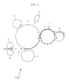
- FIG. 1 is a conceptual diagram illustrating an image forming apparatus 100, according to an exemplary embodiment of the present invention.
- the image forming apparatus 100 includes an electric charger 2, a laser scanning unit (LSU) 3 acting as an exposure unit, a developer 4, a copy unit 7, and fusers 9 and 10.
- the surface of the photoconductive drum 1 is charged with electricity by the electric charger 2, and then the LSU 3 forms an electrostatic latent image on the photoconductive drum 1.
- the developer 4 develops the electrostatic latent image with toner, to form a visible image 8.
- the visible image 8 is transferred to a recording medium by the copy unit 7.
- the visible image 8 is fixed to the recording medium, by the fusers 9 and 10, and is then carried out to the outside.
- the image forming apparatus 100 can include a provider 6, and a regulation blade 5.
- a high voltage is applied to the photoconductive drum 1, the electric charger 2, the developer 4, and the copy unit 7, by a high voltage power supply (HVPS) 42, as shown in Figure 2 .
- the HVPS 42 generates the high voltage from a power-supply voltage (e.g., 24V) produced by a switching mode power supply (SMPS), and transmits the high voltage to the photoconductive drum 1, the electric charger 2, the developer 4, and the copy unit 7.
- a power-supply voltage e.g., 24V
- SMPS switching mode power supply
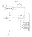
- FIG. 2 is a block diagram illustrating the image forming apparatus 100.
- the image forming apparatus 100 includes a power-supply unit 10, a power-supply cutoff unit 20, a control unit 30, and an image forming engine 40.
- the power-supply unit 10 is connected to an AC power source, converts the AC power into different power-supply voltages (e.g., 24V and 5V), and transmits the power-supply voltages of 24V and 5V to the control unit 30 and the image forming engine 40, respectively.
- different power-supply voltages e.g., 24V and 5V
- the image forming engine 40 includes a plurality of power-consumption loads, for example, a motor 41, the LSU 3, the HVPS 42, the photoconductive drum 1, an electric charger 2, the developer 4, the copy unit 7, etc.
- the motor 41, the LSU 3, and the HVPS 42 receive the power-supply voltage of 24V, from the power-supply unit 10.
- the photoconductive drum 1, the charger 2, the developer 4, and the copy unit 7 receive the high voltage generated by the HVPS 42.
- the motor 41 may be any one of a driving motor of the photoconductive drum, a toner alternating motor, and a fuser roller driving motor.
- the control unit 30 receives the power-supply voltage of 5V from the power-supply unit 30.
- the control unit 30 can be powered by a different power-supply voltage (not shown).
- the control unit 30 includes a user interface 32 and a controller 31.
- the controller 31 is connected to the user interface 32, to allow a user to enter desired printing commands to form the image, and informs the user of the image forming information.
- the controller 31 can be connected to an external host computer (not shown), over a network, so that it receives image data from the host computer. Upon receiving the image data, the controller 31 analyzes the printing commands and the image data, and converts the analyzed data into a suitable format for use by the image forming engine 40.
- the controller 31 controls the image forming engine 40 on the basis of the converted printing data, thereby controlling the image forming operation.
- the controller 31 is connected to one side of a second switching unit 21, included in the power-supply cutoff unit 20, which is switched off when the cover is being opened.
- the controller 31 determines whether a cover (not shown) of the image forming apparatus 100 is open or closed, according to the ON or OFF status of the second switching unit 21. If the cover is being opened, the controller 31 performs control operations, to halt operations of the image forming engine 40.
- the power-supply cutoff unit 20 includes a first switching unit 22 and the second switching unit 21.
- the first switching unit 22 is connected to a power-supply line extending between the power-supply unit 10 and the image forming engine 40.
- the first switching unit 22 blocks the power-supply voltage of 24V from being applied to the image forming engine 40.
- the second switching unit 21 is connected to a power-supply line extending between the power-supply unit 10 and the control unit 30.
- the second switching unit 21 blocks the power-supply voltage of 5V from being applied to the control unit 30.
- the image forming apparatus 100 includes a main body 50 and a cover 60 rotatably connected to the main body 50.
- the first switching unit 22 and the second switching unit 21 are designed to be switched on or off when brought into contact with the cover 60.
- the first switching unit 22 and the second switching unit 21 are switched off when the cover 60 is open.
- the second switching unit 21 is switched off before the first switching unit 22 is switched off.
- the first switching unit 22 is mounted to the main body 50, adjacent to a hinged end 63 of the cover 60.
- the second switching unit 21 is mounted to the main body 50, adjacent to a free end 65 of the cover 60. Therefore, if the cover 60 is partially open, only the second switching unit 21 is switched off. If the cover 60 is fully open, or open an amount that is greater than the partial amount that switches off the switching unit 21, the first and second switching units 22 and 21 are both switched off.
- a first projection 62 and a second projection 61 extend from the cover 60.
- the first projection 62 contacts the first switching unit 22, when the cover 60 is closed, and disposed adjacent to the hinged end 63 of the cover 60.
- the second projection 61 contacts the second switching unit 21, when the cover 60 is closed, and is disposed adjacent to the free end 65 of the cover 60. Therefore, the first switching unit 22 is switched on or off by the first projection 62, and the second switching unit 21 is switched on or off by the second projection 61.
- the first switching unit 22 is switched on. If the first projection 62 is released from the contact point, the first switching unit 22 is switched off. If the contact point of the second switching unit 21 is physically brought into contact with the second projection 61, the second switching unit 21 is switched on. If the second projection 62 is released from the contact point, the second switching unit 21 is switched off.
- the first and second switching units 22 and 21 are both switched off when the cover 60 is completely opened. While the cover 60 is being opened, the second switching unit 21 is switched off first. After a lapse of a predetermined time, the second switching unit 21 is switched off.
- the image forming apparatus 100 does not require a delay circuit, such as a relay circuit, used in the conventional art, and sequentially switches off the first and second switching units 22 and 21. In this way, production costs are reduced and the circuit is simplified.
- the first and second switching units 22 and 21 are both switched on.
- the power-supply unit 10 transmits the power-supply voltage of 5V to the control unit 30, via the second switching unit 21.
- the power-supply voltage of 24V is generated by the power-supply unit 10, and is applied to the image forming engine 40, via the first switching unit 22.
- the second switching unit 21 blocks the power-supply voltage of 5V from being applied to the control unit 30.
- the controller 31 of the control unit 30 detects the above-mentioned situation, determines that the cover 60 is open, and controls the image forming engine 40 to perform a shut down operation, to avoid a sudden stoppage of the image forming engine 40.
- the image forming apparatus 100 prevents the occurrence of electric shocks, due to contact with the voltages of the inner components of the apparatus 100.
- the image forming apparatus 100 is rendered interoperable, without using an additional delay circuit, and the first switching unit 22 and the second switching unit 21 are sequentially switched off.
- the power-supply voltage of 24V, applied to the image forming engine 40 is cutoff. Therefore, the image forming apparatus 100 prevents the toner and the carrier from being leaked, due to an improper shutdown of image forming engine 40.
- the image forming apparatus 100 prevents a reduction of image quality, and reduces the degree of pollution inside of the main body 50.
- the image forming apparatus 100 does not stop operation with a printing medium inserted under the roller, so that the printing medium will not become jammed.
- the first and second switching units 22 and 21 are sequentially switched off, according to an interaction with the cover 60.
- the second switching unit 21 is switched off, so that the power-supply voltage of 5V is not applied to the control unit 30.
- the controller 31 detects the partial opening of the cover 60, and outputs a command to the image forming engine 40, to trigger a shutdown operation of the image forming engine 40. If the cover 60 is fully open, the first switching unit 22 is switched off, and the power-supply voltage of 24V is cutoff from the image forming engine 40.
- the image forming engine 40 stably stops operation, so that the image forming apparatus prevents the image forming engine 40 from being suddenly halted.
- the image forming engine 40 can stably stop operation by performing a shutdown operation.
- the shutdown operation prepares the image forming engine 40 for shutdown, and thereby prevents toner loss and/or damage to the image forming engine 40.
- the method for preventing the power-supply voltage from being applied to the image forming engine 40, after the cover 60 is opened, will hereinafter be described in detail. If the cover 60 is partially opened, the contact between the second switching unit 21 and the second projection 61, mounted to the upper part of the cover 60, is broken, thereby switching off second switching unit 21. If the second switching unit 21 is switched off, the power-supply voltage of 5V is not applied to the control unit 30.
- the controller 31 detects that the cover 60 is partially opened, and generates a control command to stop the image forming engine 40. In this case, the first switching unit 22 continuously maintains the ON status, because the contact point is pressed by the first projection 62.
- the control command generated by the controller 31 may, for instance, be that the controller output switches from high voltage level to a low voltage level, or vice versa, as a result of or in response to the cut off of the control unit power supply.
- the invention is not limited to this.
- Other arrangements by which the controller 31 can pass a command to the image forming engine 40 in response to the power-supply voltage to the control unit 30 being cut off could also be used, as would be apparent to those skilled in the art.
- the cover 60 is fully opened, or opened an amount that is greater than the partial amount that switches off the switching unit 21, the contact between the first switching unit 22 and the first projection 62 is broken, so that the first switching unit 22 is switched off. If the first switching unit 22 is switched off, the power-supply voltage of 24V is not applied to the load.
- the image forming engine 40 continues to be powered during the 200msec. During this time, the image forming engine 40 can initiate the shutdown operation, such that it is properly shutdown. As a result, the image forming apparatus prevents the image forming engine 40 from being suddenly powered off, without using an additional delay circuit, such as a relay circuit. Therefore, the problems, caused by the abnormal power-supply cutoff of the image forming engine 40, can be prevented.
- an image forming apparatus includes a first switch to power off an image forming engine, and a second switch to power off a control unit.
- the first and second switches are sequentially switched off, by the opening of a cover.
- the first and second switches are arranged to allow the power-supply voltage, applied to the image forming engine, to be cutoff after the power-supply voltage is cutoff from the control unit.
- the image forming engine stops operation, so that the image forming apparatus can delay a cutoff time of the power-supply voltage applied to the image forming engine, when the cover is opened, without using a delay circuit such as the relay circuit, so that the production costs are reduced and the circuit is simplified.
Landscapes
- Physics & Mathematics (AREA)
- General Physics & Mathematics (AREA)
- Engineering & Computer Science (AREA)
- Microelectronics & Electronic Packaging (AREA)
- Control Or Security For Electrophotography (AREA)
- Accessory Devices And Overall Control Thereof (AREA)
- Studio Devices (AREA)
Abstract
Description
- The present invention relates to an image forming apparatus, and more particularly, to an image forming apparatus arranged to reduce accidents and other undesirable consequences of a cover of the apparatus being opened.
- Generally, an image forming apparatus, for example, electrophotographic-type image forming apparatus, uses an electrophotographic printing scheme. The apparatus projects a laser beam onto a photoconductive drum, to form an electrostatic latent image, and converts the electrostatic latent image into a visible image, using a developer mounted to a developing apparatus. The visible image is transferred onto paper, and then fixed to the paper with heat and pressure. There are a variety of electrophotographic image forming apparatuses, for example, a laser beam printer (LBP), a duplicating machine, a facsimile, a multi-functional device, etc.
- The image forming apparatus includes a power-supply unit to convert an AC power into a DC power, according to voltages of individual loads of an image forming engine. The image forming engine basically requires a low-voltage, power-supply voltage of about 24V, and a high-voltage, power-supply voltage of about 100Kv. The power-supply unit provides a power-supply voltage of 5V to a control unit that controls the image forming operations.
- If an after-sale (A/S) repairman or a user opens a cover rotatably connected to the front or lateral side of a main body of the apparatus, to inspect or maintain the image forming apparatus, the repairman or user may be in danger from a high voltage inside of the main body. For this purpose, the image forming apparatus includes a first switch and a second switch. If the cover is open, the first switch blocks the power-supply voltage of 5V from being applied from the power-supply unit to the control unit, and the second switch blocks the power-supply voltage of 24V from being applied from the power-supply unit to the image forming engine. The first and second switches are simultaneously switched off, when the cover of the image forming apparatus is open, so that the power-supply voltages, applied to the control unit and the image forming engine, are blocked. As a result, the repairman or user can be protected from an electric shock.
- However, while the cover is open, if the first and second switches are simultaneously switched off, and the power-supply voltages applied to the control unit and the image forming engine are simultaneously turned off, the image forming engine suddenly stops operation. This can result in the image forming apparatus being unstably powered off. For example, in the case of a developing process, if a high voltage for controlling a toner is not applied to the developing process of the image forming apparatus, the developing process stops operation. In this case, a developing roller of the developer does not immediately stop operation, but instead, continuously rotates by inertia, for a relatively long period of time. A carrier for carrying the toner and the toner are not controlled by the high voltage, so that the carrier and toner may leak out. The leaked carrier and toner pollutes inner parts of the image forming apparatus, such that the printing performance and the image quality may be seriously degraded. In addition, the fine structure of the surface of the photoconductive drum can be damaged, resulting in degraded printing performance, and a reduced lifetime of the apparatus. In addition, if the image forming apparatus suddenly stops operation, gears may be engage with each other, complicating the disassembly thereof. If the image forming apparatus suddenly stops operation, when paper is inserted under the roller, the paper may become jammed.
- A representative image forming apparatus capable of solving the above-mentioned problems has been disclosed in Japanese Patent Laid-open No.
2006-030702 2006-030702 - However, the above-mentioned conventional art disclosed in Japanese Patent Laid-open No.
2006-030702 - Aspects of the invention to provide an image forming apparatus to delay a cutoff time of a power-supply voltage, applied to an image forming engine, when a cover is opened, without using a delay circuit, such as a relay circuit. This configuration results in lower production costs and simplified circuitry.
- Aspects of the present invention relate to an image forming apparatus including: a main body; a cover rotatably connected to the main body; a power-supply unit to generate a first power-supply voltage and a second power-supply voltage; an image forming engine to receive the first power-supply voltage from the power-supply unit; a control unit to receive the second power-supply voltage from the power-supply unit, and to stop operation of the image forming engine when the second power-supply voltage is cutoff; and a power-supply cutoff unit to delay a cutoff time of the first power-supply voltage, as compared to a cutoff time of the second power-supply voltage, when the cover is opened.
- In accordance with another aspect of the present invention, there is provided an image forming apparatus including: a main body; a cover rotatably connected to the main body; an image forming engine; a control unit to power off the image forming engine, if a power-supply voltage is cutoff; a power-supply unit to power on the image forming engine and the control unit; a first switching unit to power off the control unit, if the cover is partially opened; and a second switching unit to power off the image forming engine, if the cover is fully opened.
- Additional aspects and/or advantages of the invention will be set forth in part in the description which follows and, in part, will be obvious from the description, or may be learned by practice of the invention.
- Embodiments of the invention will now be described, by way of example, with reference to the accompanying drawings, in which:
-
Figure 1 is a conceptual diagram illustrating an image forming apparatus according to an exemplary embodiment of the present invention; -
Figure 2 is a block diagram illustrating an image forming apparatus, according to the exemplary embodiment of the present invention; -
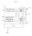
Figure 3 shows the appearance of the image forming apparatus with a closed cover, according to aspects of the present invention; -
Figure 4 shows the appearance of the image forming apparatus with a partially-opened cover, according to aspects of the present invention; and -
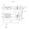
Figure 5 shows the appearance of the image forming apparatus with a fully-opened cover, according to aspects of the present invention. -
Figure 1 is a conceptual diagram illustrating animage forming apparatus 100, according to an exemplary embodiment of the present invention. Referring toFigure 1 , theimage forming apparatus 100 includes anelectric charger 2, a laser scanning unit (LSU) 3 acting as an exposure unit, adeveloper 4, acopy unit 7, andfusers 9 and 10. The surface of the photoconductive drum 1 is charged with electricity by theelectric charger 2, and then the LSU 3 forms an electrostatic latent image on the photoconductive drum 1. Thedeveloper 4 develops the electrostatic latent image with toner, to form avisible image 8. Thevisible image 8 is transferred to a recording medium by thecopy unit 7. Thevisible image 8 is fixed to the recording medium, by thefusers 9 and 10, and is then carried out to the outside. - The
image forming apparatus 100 can include a provider 6, and aregulation blade 5. A high voltage is applied to the photoconductive drum 1, theelectric charger 2, thedeveloper 4, and thecopy unit 7, by a high voltage power supply (HVPS) 42, as shown inFigure 2 . TheHVPS 42 generates the high voltage from a power-supply voltage (e.g., 24V) produced by a switching mode power supply (SMPS), and transmits the high voltage to the photoconductive drum 1, theelectric charger 2, thedeveloper 4, and thecopy unit 7. -
Figure 2 is a block diagram illustrating theimage forming apparatus 100. Referring toFigure 2 , theimage forming apparatus 100 includes a power-supply unit 10, a power-supply cutoff unit 20, acontrol unit 30, and animage forming engine 40. - The power-
supply unit 10 is connected to an AC power source, converts the AC power into different power-supply voltages (e.g., 24V and 5V), and transmits the power-supply voltages of 24V and 5V to thecontrol unit 30 and theimage forming engine 40, respectively. - The
image forming engine 40 includes a plurality of power-consumption loads, for example, amotor 41, the LSU 3, the HVPS 42, the photoconductive drum 1, anelectric charger 2, thedeveloper 4, thecopy unit 7, etc. Themotor 41, the LSU 3, and theHVPS 42 receive the power-supply voltage of 24V, from the power-supply unit 10. The photoconductive drum 1, thecharger 2, thedeveloper 4, and thecopy unit 7 receive the high voltage generated by theHVPS 42. Themotor 41 may be any one of a driving motor of the photoconductive drum, a toner alternating motor, and a fuser roller driving motor. - The
control unit 30 receives the power-supply voltage of 5V from the power-supply unit 30. Thecontrol unit 30 can be powered by a different power-supply voltage (not shown). Thecontrol unit 30 includes auser interface 32 and acontroller 31. - The
controller 31 is connected to theuser interface 32, to allow a user to enter desired printing commands to form the image, and informs the user of the image forming information. Thecontroller 31 can be connected to an external host computer (not shown), over a network, so that it receives image data from the host computer. Upon receiving the image data, thecontroller 31 analyzes the printing commands and the image data, and converts the analyzed data into a suitable format for use by theimage forming engine 40. - The
controller 31 controls theimage forming engine 40 on the basis of the converted printing data, thereby controlling the image forming operation. - Particularly, the
controller 31 is connected to one side of asecond switching unit 21, included in the power-supply cutoff unit 20, which is switched off when the cover is being opened. Thecontroller 31 determines whether a cover (not shown) of theimage forming apparatus 100 is open or closed, according to the ON or OFF status of thesecond switching unit 21. If the cover is being opened, thecontroller 31 performs control operations, to halt operations of theimage forming engine 40. - The power-
supply cutoff unit 20 includes afirst switching unit 22 and thesecond switching unit 21. Thefirst switching unit 22 is connected to a power-supply line extending between the power-supply unit 10 and theimage forming engine 40. Thefirst switching unit 22 blocks the power-supply voltage of 24V from being applied to theimage forming engine 40. Thesecond switching unit 21 is connected to a power-supply line extending between the power-supply unit 10 and thecontrol unit 30. Thesecond switching unit 21 blocks the power-supply voltage of 5V from being applied to thecontrol unit 30. - Referring to
Figures 3 to 5 , theimage forming apparatus 100 includes amain body 50 and acover 60 rotatably connected to themain body 50. Thefirst switching unit 22 and thesecond switching unit 21 are designed to be switched on or off when brought into contact with thecover 60. In more detail, thefirst switching unit 22 and thesecond switching unit 21 are switched off when thecover 60 is open. When thecover 60 is being opened, thesecond switching unit 21 is switched off before thefirst switching unit 22 is switched off. - The
first switching unit 22 is mounted to themain body 50, adjacent to a hingedend 63 of thecover 60. Thesecond switching unit 21 is mounted to themain body 50, adjacent to afree end 65 of thecover 60. Therefore, if thecover 60 is partially open, only thesecond switching unit 21 is switched off. If thecover 60 is fully open, or open an amount that is greater than the partial amount that switches off the switchingunit 21, the first andsecond switching units - A
first projection 62 and asecond projection 61 extend from thecover 60. Thefirst projection 62 contacts thefirst switching unit 22, when thecover 60 is closed, and disposed adjacent to the hingedend 63 of thecover 60. Thesecond projection 61 contacts thesecond switching unit 21, when thecover 60 is closed, and is disposed adjacent to thefree end 65 of thecover 60. Therefore, thefirst switching unit 22 is switched on or off by thefirst projection 62, and thesecond switching unit 21 is switched on or off by thesecond projection 61. In other words, if a contact point of thefirst switching unit 22 is physically brought into contact with thefirst projection 62, thefirst switching unit 22 is switched on. If thefirst projection 62 is released from the contact point, thefirst switching unit 22 is switched off. If the contact point of thesecond switching unit 21 is physically brought into contact with thesecond projection 61, thesecond switching unit 21 is switched on. If thesecond projection 62 is released from the contact point, thesecond switching unit 21 is switched off. - Therefore, the first and
second switching units cover 60 is completely opened. While thecover 60 is being opened, thesecond switching unit 21 is switched off first. After a lapse of a predetermined time, thesecond switching unit 21 is switched off. As a result, theimage forming apparatus 100 does not require a delay circuit, such as a relay circuit, used in the conventional art, and sequentially switches off the first andsecond switching units - In the operation of the first and
second switching units cover 60 is closed, as shown inFigure 3 , the first andsecond switching units supply unit 10 transmits the power-supply voltage of 5V to thecontrol unit 30, via thesecond switching unit 21. At the same time, the power-supply voltage of 24V is generated by the power-supply unit 10, and is applied to theimage forming engine 40, via thefirst switching unit 22. - As shown in
Figure 4 , if an A/S repairman or a user partially opens thecover 60, thesecond switching unit 21 is switched off, while thefirst switching unit 22 remains on. Therefore, thesecond switching unit 21 blocks the power-supply voltage of 5V from being applied to thecontrol unit 30. In this case, thecontroller 31 of thecontrol unit 30 detects the above-mentioned situation, determines that thecover 60 is open, and controls theimage forming engine 40 to perform a shut down operation, to avoid a sudden stoppage of theimage forming engine 40. - As shown in
Figure 5 , if thecover 60 is fully opened, thefirst switching unit 22 and thesecond switching unit 21 are both switched off, and the power-supply voltage of 24V is not applied to theimage forming engine 40. Therefore, theimage forming apparatus 100 prevents the occurrence of electric shocks, due to contact with the voltages of the inner components of theapparatus 100. - In other words, if the
cover 60 is completely open, theimage forming apparatus 100 is rendered interoperable, without using an additional delay circuit, and thefirst switching unit 22 and thesecond switching unit 21 are sequentially switched off. As a result, after theimage forming engine 40 stably stops operation, the power-supply voltage of 24V, applied to theimage forming engine 40, is cutoff. Therefore, theimage forming apparatus 100 prevents the toner and the carrier from being leaked, due to an improper shutdown ofimage forming engine 40. Theimage forming apparatus 100 prevents a reduction of image quality, and reduces the degree of pollution inside of themain body 50. Theimage forming apparatus 100 does not stop operation with a printing medium inserted under the roller, so that the printing medium will not become jammed. - In brief, if the
cover 60 of themain body 50 is opened during the image forming operation, the first andsecond switching units cover 60. As soon as thecover 50 is partially opened, thesecond switching unit 21 is switched off, so that the power-supply voltage of 5V is not applied to thecontrol unit 30. Thecontroller 31 detects the partial opening of thecover 60, and outputs a command to theimage forming engine 40, to trigger a shutdown operation of theimage forming engine 40. If thecover 60 is fully open, thefirst switching unit 22 is switched off, and the power-supply voltage of 24V is cutoff from theimage forming engine 40. A delay between the switch off ofsecond switching unit 21, and the switch off of thefirst switching unit 22, theimage forming engine 40 stably stops operation, so that the image forming apparatus prevents theimage forming engine 40 from being suddenly halted. Theimage forming engine 40 can stably stop operation by performing a shutdown operation. The shutdown operation prepares theimage forming engine 40 for shutdown, and thereby prevents toner loss and/or damage to theimage forming engine 40. - The method for preventing the power-supply voltage from being applied to the
image forming engine 40, after thecover 60 is opened, will hereinafter be described in detail. If thecover 60 is partially opened, the contact between thesecond switching unit 21 and thesecond projection 61, mounted to the upper part of thecover 60, is broken, thereby switching offsecond switching unit 21. If thesecond switching unit 21 is switched off, the power-supply voltage of 5V is not applied to thecontrol unit 30. - If the power-supply voltage of 5V is not applied to the
control unit 30, thecontroller 31 detects that thecover 60 is partially opened, and generates a control command to stop theimage forming engine 40. In this case, thefirst switching unit 22 continuously maintains the ON status, because the contact point is pressed by thefirst projection 62. - The control command generated by the
controller 31 may, for instance, be that the controller output switches from high voltage level to a low voltage level, or vice versa, as a result of or in response to the cut off of the control unit power supply. However, the invention is not limited to this. Other arrangements by which thecontroller 31 can pass a command to theimage forming engine 40 in response to the power-supply voltage to thecontrol unit 30 being cut off could also be used, as would be apparent to those skilled in the art. - If the
cover 60 is fully opened, or opened an amount that is greater than the partial amount that switches off the switchingunit 21, the contact between thefirst switching unit 22 and thefirst projection 62 is broken, so that thefirst switching unit 22 is switched off. If thefirst switching unit 22 is switched off, the power-supply voltage of 24V is not applied to the load. - A predetermined time of about 200msec elapses before the
cover 60 is fully opened. Theimage forming engine 40 continues to be powered during the 200msec. During this time, theimage forming engine 40 can initiate the shutdown operation, such that it is properly shutdown. As a result, the image forming apparatus prevents theimage forming engine 40 from being suddenly powered off, without using an additional delay circuit, such as a relay circuit. Therefore, the problems, caused by the abnormal power-supply cutoff of theimage forming engine 40, can be prevented. - As is apparent from the above description, an image forming apparatus, according to aspects of the present invention, includes a first switch to power off an image forming engine, and a second switch to power off a control unit. The first and second switches are sequentially switched off, by the opening of a cover. The first and second switches are arranged to allow the power-supply voltage, applied to the image forming engine, to be cutoff after the power-supply voltage is cutoff from the control unit. If the power-supply voltage applied to the control unit is cutoff, the image forming engine stops operation, so that the image forming apparatus can delay a cutoff time of the power-supply voltage applied to the image forming engine, when the cover is opened, without using a delay circuit such as the relay circuit, so that the production costs are reduced and the circuit is simplified.
- Although a few embodiments of the present invention have been shown and described, it would be appreciated by those skilled in the art that changes may be made in these embodiments without departing from the principles of the invention, the scope of which is defined in the claims.
Claims (11)
- An image forming apparatus comprising:a main body;a cover pivotably attached to the main body;a power-supply unit, for generating a first voltage and a second voltage;image forming means, arranged to receive the first voltage from the power-supply unit;control means for receiving the second voltage from the power-supply unit, and for stopping an operation of the image forming means when the second voltage is cut off; andpower-supply cut-off means for delaying a cut-off time of the first voltage as compared to a cut-off time of the second voltage, when the cover is being opened.
- The image forming apparatus according to claim 1, wherein the power-supply cut-off means comprises:a first switching unit for cutting off the first voltage; anda second switching unit for cutting off the second voltage,wherein the first switching unit and the second switching unit are arranged to cut off the first voltage and the second voltage at different times, when the cover is being opened.
- The image forming apparatus according to claim 2, wherein the first and second switching units are arranged to be switched on when in contact with the cover, and switched off when not in contact with the cover.
- The image forming apparatus according to claim 2 or 3, wherein the first switching unit is arranged to be switched off after the second switching unit, when the cover is being opened.
- The image forming apparatus according to claim 2, 3 or 4, wherein the first and second switching units are disposed in the main body, adjacent to the cover.
- The image forming apparatus according to claim 5, further comprising:a first projection disposed adjacent to a hinged end of the cover; anda second projection disposed adjacent to a free end of the cover,wherein the image forming apparatus is arranged such that,
if the cover is fully open, a contact is broken between the first switching unit and the first projection, such that the first switching unit is switched off, and
if the cover is partially open, a contact is broken between the second switching unit and the second projection, such that the second switching unit is switched off. - An image forming apparatus according to any one of claims 2 to 6, wherein:the first switching unit is arranged to power off the control unit, if the cover is partially open; andthe second switching unit is arranged to power off the image forming means, if the cover is fully open.
- The image forming apparatus according to claim 1, further comprising:a first projection extending from the cover, arranged to selectively contact the first switching unit, such that the first voltage flows through the first switching unit, when the cover is closed, and the first switching unit cuts off the first voltage when the cover is fully opened; anda second projection extending from the cover, arranged to selectively contact the second switching unit, such that the second voltage flows through the second switching unit, when the cover is closed, and the second switching unit cuts off the second voltage, when the cover is partially opened.
- The image forming apparatus according to claim 8, wherein when the cover is being opened, the second switching unit is arranged to cut off the second voltage for about 200ms, before the first switching unit cuts off the first voltage.
- The image forming apparatus according to claim 8 or 9, wherein the control unit is arranged to stop the operation of the image forming means before the first voltage is cut off.
- The image forming apparatus according to claim 8, 9 or 10, wherein the control unit is arranged to control the image forming means to perform a shutdown operation before the first voltage is cut off by the first switch.
Applications Claiming Priority (1)
| Application Number | Priority Date | Filing Date | Title |
|---|---|---|---|
| KR1020070016017A KR101354215B1 (en) | 2007-02-15 | 2007-02-15 | Image forming apparatus |
Publications (3)
| Publication Number | Publication Date |
|---|---|
| EP1959307A2 true EP1959307A2 (en) | 2008-08-20 |
| EP1959307A3 EP1959307A3 (en) | 2014-07-30 |
| EP1959307B1 EP1959307B1 (en) | 2019-04-03 |
Family
ID=39420766
Family Applications (1)
| Application Number | Title | Priority Date | Filing Date |
|---|---|---|---|
| EP08101477.1A Ceased EP1959307B1 (en) | 2007-02-15 | 2008-02-11 | Image Forming Apparatus having a cover |
Country Status (4)
| Country | Link |
|---|---|
| US (1) | US7761022B2 (en) |
| EP (1) | EP1959307B1 (en) |
| KR (1) | KR101354215B1 (en) |
| CN (1) | CN101246331B (en) |
Cited By (1)
| Publication number | Priority date | Publication date | Assignee | Title |
|---|---|---|---|---|
| EP2405304A3 (en) * | 2010-07-05 | 2016-04-06 | Samsung Electronics Co., Ltd. | Switching mode power supply and method of supplying power by using the same |
Families Citing this family (9)
| Publication number | Priority date | Publication date | Assignee | Title |
|---|---|---|---|---|
| KR101720185B1 (en) * | 2009-10-15 | 2017-03-28 | 에스프린팅솔루션 주식회사 | Image forming apparatus |
| CN103294110B (en) * | 2012-02-29 | 2017-06-06 | 光通天下网络科技有限公司 | Server |
| JP6004783B2 (en) * | 2012-06-28 | 2016-10-12 | キヤノン株式会社 | Image forming apparatus and control method thereof |
| JP6207261B2 (en) * | 2013-06-28 | 2017-10-04 | キヤノン株式会社 | Image forming apparatus |
| JP5932738B2 (en) * | 2013-09-02 | 2016-06-08 | キヤノン株式会社 | Electronic device and power control method for control unit of electronic device |
| JP2016173404A (en) * | 2015-03-16 | 2016-09-29 | 株式会社リコー | Apparatus and image forming apparatus |
| US10379487B2 (en) * | 2015-10-15 | 2019-08-13 | Canon Kabushiki Kaisha | Apparatus for determining whether door is open or closed and image forming apparatus |
| JP7102232B2 (en) * | 2018-05-30 | 2022-07-19 | キヤノン株式会社 | Image forming device |
| CN110858713A (en) * | 2018-08-24 | 2020-03-03 | 深圳光峰科技股份有限公司 | Electric shock prevention protection system, projection equipment and electric shock prevention protection method |
Citations (1)
| Publication number | Priority date | Publication date | Assignee | Title |
|---|---|---|---|---|
| JP2006030702A (en) | 2004-07-16 | 2006-02-02 | Fuji Xerox Co Ltd | Image forming apparatus |
Family Cites Families (9)
| Publication number | Priority date | Publication date | Assignee | Title |
|---|---|---|---|---|
| JP2776690B2 (en) * | 1992-06-17 | 1998-07-16 | 日本電気株式会社 | Laser printer safety devices |
| JPH1152813A (en) * | 1997-07-29 | 1999-02-26 | Ricoh Co Ltd | Image forming device |
| KR100449736B1 (en) * | 2002-08-24 | 2004-09-22 | 삼성전자주식회사 | Apparatus for cutting off power supply of printer |
| WO2005038537A1 (en) * | 2003-10-16 | 2005-04-28 | Seiko Epson Corporation | Image shaping apparatus and control method of that apparatus |
| JP2006184329A (en) * | 2004-12-24 | 2006-07-13 | Ricoh Co Ltd | Image forming apparatus |
| KR100677571B1 (en) * | 2005-03-22 | 2007-02-02 | 삼성전자주식회사 | Driving control device of the image forming apparatus |
| KR100813965B1 (en) * | 2005-11-04 | 2008-03-14 | 삼성전자주식회사 | Method and device for detecting cover open of image forming apparatus and power supply control method according to cover open of image forming apparatus |
| KR101225080B1 (en) * | 2006-07-20 | 2013-01-22 | 삼성전자주식회사 | Power control method and apparatus of image forming device |
| KR101324185B1 (en) * | 2006-11-27 | 2013-11-06 | 삼성전자주식회사 | Image forming apparatus and power control method thereof |
-
2007
- 2007-02-15 KR KR1020070016017A patent/KR101354215B1/en not_active Expired - Fee Related
-
2008
- 2008-02-05 US US12/025,964 patent/US7761022B2/en active Active
- 2008-02-11 EP EP08101477.1A patent/EP1959307B1/en not_active Ceased
- 2008-02-14 CN CN2008100057964A patent/CN101246331B/en not_active Expired - Fee Related
Patent Citations (1)
| Publication number | Priority date | Publication date | Assignee | Title |
|---|---|---|---|---|
| JP2006030702A (en) | 2004-07-16 | 2006-02-02 | Fuji Xerox Co Ltd | Image forming apparatus |
Cited By (1)
| Publication number | Priority date | Publication date | Assignee | Title |
|---|---|---|---|---|
| EP2405304A3 (en) * | 2010-07-05 | 2016-04-06 | Samsung Electronics Co., Ltd. | Switching mode power supply and method of supplying power by using the same |
Also Published As
| Publication number | Publication date |
|---|---|
| US7761022B2 (en) | 2010-07-20 |
| EP1959307A3 (en) | 2014-07-30 |
| US20080199203A1 (en) | 2008-08-21 |
| KR101354215B1 (en) | 2014-01-22 |
| CN101246331B (en) | 2010-11-03 |
| CN101246331A (en) | 2008-08-20 |
| EP1959307B1 (en) | 2019-04-03 |
| KR20080076281A (en) | 2008-08-20 |
Similar Documents
| Publication | Publication Date | Title |
|---|---|---|
| EP1959307B1 (en) | Image Forming Apparatus having a cover | |
| JP5984514B2 (en) | Power supply device and image forming apparatus having the same | |
| JP2010057327A (en) | Power supply device and image forming device with the same | |
| JP2011186378A (en) | Process cartridge and image forming device | |
| JP2015036336A (en) | Post-processing device and image formation device | |
| US11487235B2 (en) | Printer system switching a connection for supply of AC voltage to a voltage source | |
| US8417134B2 (en) | Electrophotographic color image forming apparatus | |
| KR101545449B1 (en) | Image forming apparatus | |
| JP4894884B2 (en) | Image forming apparatus, image forming apparatus control method, and image forming apparatus control program | |
| JP2009080426A (en) | Image forming apparatus | |
| JP5560829B2 (en) | Power supply control device, image processing device, power supply control program | |
| JP4207840B2 (en) | Image forming apparatus | |
| JP4023719B2 (en) | FEEDING DEVICE HAVING INTERLOCK CIRCUIT AND IMAGE FORMING DEVICE | |
| JP6057603B2 (en) | Image forming apparatus | |
| JP2019207378A (en) | Image forming apparatus | |
| JP2006030702A (en) | Image forming apparatus | |
| JP2005181603A (en) | Image forming apparatus | |
| JP6776042B2 (en) | Power supply device, image forming device, power supply control method | |
| JP7552157B2 (en) | Image forming device | |
| JP7475837B2 (en) | Image forming device | |
| JP4476332B2 (en) | Image forming apparatus | |
| JP2004034465A (en) | Switch device and image forming device | |
| JPH05241387A (en) | Image forming device | |
| JP2013003219A (en) | Image forming apparatus, image formation control method and image formation control program | |
| JP2005227520A (en) | Image forming apparatus |
Legal Events
| Date | Code | Title | Description |
|---|---|---|---|
| PUAI | Public reference made under article 153(3) epc to a published international application that has entered the european phase |
Free format text: ORIGINAL CODE: 0009012 |
|
| AK | Designated contracting states |
Kind code of ref document: A2 Designated state(s): AT BE BG CH CY CZ DE DK EE ES FI FR GB GR HR HU IE IS IT LI LT LU LV MC MT NL NO PL PT RO SE SI SK TR |
|
| AX | Request for extension of the european patent |
Extension state: AL BA MK RS |
|
| RIN1 | Information on inventor provided before grant (corrected) |
Inventor name: SEO, IN CHANG |
|
| RTI1 | Title (correction) |
Free format text: IMAGE FORMING APPARATUS HAVING A COVER |
|
| RAP1 | Party data changed (applicant data changed or rights of an application transferred) |
Owner name: SAMSUNG ELECTRONICS CO., LTD. |
|
| PUAL | Search report despatched |
Free format text: ORIGINAL CODE: 0009013 |
|
| AK | Designated contracting states |
Kind code of ref document: A3 Designated state(s): AT BE BG CH CY CZ DE DK EE ES FI FR GB GR HR HU IE IS IT LI LT LU LV MC MT NL NO PL PT RO SE SI SK TR |
|
| AX | Request for extension of the european patent |
Extension state: AL BA MK RS |
|
| RIC1 | Information provided on ipc code assigned before grant |
Ipc: G03G 21/16 20060101ALI20140624BHEP Ipc: G03G 15/00 20060101AFI20140624BHEP |
|
| 17P | Request for examination filed |
Effective date: 20150121 |
|
| RBV | Designated contracting states (corrected) |
Designated state(s): AT BE BG CH CY CZ DE DK EE ES FI FR GB GR HR HU IE IS IT LI LT LU LV MC MT NL NO PL PT RO SE SI SK TR |
|
| AKX | Designation fees paid |
Designated state(s): DE FR GB NL |
|
| AXX | Extension fees paid |
Extension state: AL Extension state: RS Extension state: MK Extension state: BA |
|
| RAP1 | Party data changed (applicant data changed or rights of an application transferred) |
Owner name: S-PRINTING SOLUTION CO., LTD. |
|
| RAP1 | Party data changed (applicant data changed or rights of an application transferred) |
Owner name: HP PRINTING KOREA CO., LTD. |
|
| GRAP | Despatch of communication of intention to grant a patent |
Free format text: ORIGINAL CODE: EPIDOSNIGR1 |
|
| STAA | Information on the status of an ep patent application or granted ep patent |
Free format text: STATUS: GRANT OF PATENT IS INTENDED |
|
| INTG | Intention to grant announced |
Effective date: 20181214 |
|
| RIN1 | Information on inventor provided before grant (corrected) |
Inventor name: SEO, IN CHANG |
|
| GRAS | Grant fee paid |
Free format text: ORIGINAL CODE: EPIDOSNIGR3 |
|
| GRAA | (expected) grant |
Free format text: ORIGINAL CODE: 0009210 |
|
| STAA | Information on the status of an ep patent application or granted ep patent |
Free format text: STATUS: THE PATENT HAS BEEN GRANTED |
|
| AK | Designated contracting states |
Kind code of ref document: B1 Designated state(s): DE FR GB NL |
|
| REG | Reference to a national code |
Ref country code: GB Ref legal event code: FG4D |
|
| REG | Reference to a national code |
Ref country code: DE Ref legal event code: R096 Ref document number: 602008059569 Country of ref document: DE |
|
| REG | Reference to a national code |
Ref country code: NL Ref legal event code: FP |
|
| REG | Reference to a national code |
Ref country code: NL Ref legal event code: PD Owner name: HEWLETT-PACKARD DEVELOPMENT COMPANY, L.P.; US Free format text: DETAILS ASSIGNMENT: CHANGE OF OWNER(S), CHANGE OF LEGAL ENTITY; FORMER OWNER NAME: HP PRINTING KOREA CO., LTD. Effective date: 20191030 |
|
| REG | Reference to a national code |
Ref country code: DE Ref legal event code: R082 Ref document number: 602008059569 Country of ref document: DE Representative=s name: SCHOPPE, ZIMMERMANN, STOECKELER, ZINKLER, SCHE, DE Ref country code: DE Ref legal event code: R081 Ref document number: 602008059569 Country of ref document: DE Owner name: HEWLETT-PACKARD DEVELOPMENT COMPANY, L.P., SPR, US Free format text: FORMER OWNER: HP PRINTING KOREA CO., LTD., SUWON-SI, GYEONGGI-DO, KR |
|
| REG | Reference to a national code |
Ref country code: DE Ref legal event code: R097 Ref document number: 602008059569 Country of ref document: DE |
|
| PLBE | No opposition filed within time limit |
Free format text: ORIGINAL CODE: 0009261 |
|
| STAA | Information on the status of an ep patent application or granted ep patent |
Free format text: STATUS: NO OPPOSITION FILED WITHIN TIME LIMIT |
|
| 26N | No opposition filed |
Effective date: 20200106 |
|
| REG | Reference to a national code |
Ref country code: GB Ref legal event code: 732E Free format text: REGISTERED BETWEEN 20200917 AND 20200923 |
|
| PGFP | Annual fee paid to national office [announced via postgrant information from national office to epo] |
Ref country code: NL Payment date: 20210120 Year of fee payment: 14 |
|
| PGFP | Annual fee paid to national office [announced via postgrant information from national office to epo] |
Ref country code: GB Payment date: 20210120 Year of fee payment: 14 |
|
| PGFP | Annual fee paid to national office [announced via postgrant information from national office to epo] |
Ref country code: FR Payment date: 20210608 Year of fee payment: 15 |
|
| PGFP | Annual fee paid to national office [announced via postgrant information from national office to epo] |
Ref country code: DE Payment date: 20210528 Year of fee payment: 15 |
|
| REG | Reference to a national code |
Ref country code: NL Ref legal event code: MM Effective date: 20220301 |
|
| GBPC | Gb: european patent ceased through non-payment of renewal fee |
Effective date: 20220211 |
|
| PG25 | Lapsed in a contracting state [announced via postgrant information from national office to epo] |
Ref country code: NL Free format text: LAPSE BECAUSE OF NON-PAYMENT OF DUE FEES Effective date: 20220301 |
|
| PG25 | Lapsed in a contracting state [announced via postgrant information from national office to epo] |
Ref country code: GB Free format text: LAPSE BECAUSE OF NON-PAYMENT OF DUE FEES Effective date: 20220211 |
|
| REG | Reference to a national code |
Ref country code: DE Ref legal event code: R119 Ref document number: 602008059569 Country of ref document: DE |
|
| PG25 | Lapsed in a contracting state [announced via postgrant information from national office to epo] |
Ref country code: FR Free format text: LAPSE BECAUSE OF NON-PAYMENT OF DUE FEES Effective date: 20230228 Ref country code: DE Free format text: LAPSE BECAUSE OF NON-PAYMENT OF DUE FEES Effective date: 20230901 |