EP1959286B1 - Zoom lens and image pickup apparatus having the same - Google Patents
Zoom lens and image pickup apparatus having the same Download PDFInfo
- Publication number
- EP1959286B1 EP1959286B1 EP08151283.2A EP08151283A EP1959286B1 EP 1959286 B1 EP1959286 B1 EP 1959286B1 EP 08151283 A EP08151283 A EP 08151283A EP 1959286 B1 EP1959286 B1 EP 1959286B1
- Authority
- EP
- European Patent Office
- Prior art keywords
- lens
- lens unit
- zoom lens
- zoom
- exemplary embodiment
- Prior art date
- Legal status (The legal status is an assumption and is not a legal conclusion. Google has not performed a legal analysis and makes no representation as to the accuracy of the status listed.)
- Not-in-force
Links
- 230000003287 optical effect Effects 0.000 claims description 126
- 239000000463 material Substances 0.000 claims description 37
- 238000006243 chemical reaction Methods 0.000 claims description 3
- 230000004075 alteration Effects 0.000 description 142
- 238000010586 diagram Methods 0.000 description 62
- 239000011521 glass Substances 0.000 description 18
- 239000006185 dispersion Substances 0.000 description 16
- 238000012937 correction Methods 0.000 description 14
- 230000014509 gene expression Effects 0.000 description 13
- 206010010071 Coma Diseases 0.000 description 9
- 125000001475 halogen functional group Chemical group 0.000 description 9
- 230000007423 decrease Effects 0.000 description 7
- 102220008663 rs193922450 Human genes 0.000 description 6
- 239000000758 substrate Substances 0.000 description 6
- 102220368492 c.114C>T Human genes 0.000 description 5
- 230000008859 change Effects 0.000 description 5
- 230000003247 decreasing effect Effects 0.000 description 5
- 230000000694 effects Effects 0.000 description 5
- 102220305863 rs1015663503 Human genes 0.000 description 5
- 102220204171 rs1057522533 Human genes 0.000 description 5
- 102220205468 rs1057523833 Human genes 0.000 description 5
- 102220214374 rs1060504419 Human genes 0.000 description 5
- 102220228145 rs1064794513 Human genes 0.000 description 5
- 102220007336 rs111033642 Human genes 0.000 description 5
- 102220017034 rs116525289 Human genes 0.000 description 5
- 102220274895 rs1260697914 Human genes 0.000 description 5
- 102220297462 rs1264640823 Human genes 0.000 description 5
- 102220279556 rs1305090923 Human genes 0.000 description 5
- 102220264750 rs1305455942 Human genes 0.000 description 5
- 102220123988 rs138203039 Human genes 0.000 description 5
- 102220132826 rs139286202 Human genes 0.000 description 5
- 102220208315 rs141965142 Human genes 0.000 description 5
- 102220043272 rs143261167 Human genes 0.000 description 5
- 102220265263 rs1449870708 Human genes 0.000 description 5
- 102220131033 rs145667920 Human genes 0.000 description 5
- 102220264498 rs1457262106 Human genes 0.000 description 5
- 102220254263 rs1468361143 Human genes 0.000 description 5
- 102220101619 rs149717696 Human genes 0.000 description 5
- 102220017114 rs150867836 Human genes 0.000 description 5
- 102220067506 rs150937126 Human genes 0.000 description 5
- 102220287052 rs1555054149 Human genes 0.000 description 5
- 102220280436 rs1555280114 Human genes 0.000 description 5
- 102220270437 rs1555462102 Human genes 0.000 description 5
- 102220272282 rs1555570413 Human genes 0.000 description 5
- 102220306639 rs1555879894 Human genes 0.000 description 5
- 102220062245 rs1800369 Human genes 0.000 description 5
- 102220127561 rs189308547 Human genes 0.000 description 5
- 102220172465 rs1893316 Human genes 0.000 description 5
- 102220126604 rs199625892 Human genes 0.000 description 5
- 102220053946 rs199631710 Human genes 0.000 description 5
- 102220101549 rs199890548 Human genes 0.000 description 5
- 102220076495 rs200649587 Human genes 0.000 description 5
- 102220033625 rs281865531 Human genes 0.000 description 5
- 102220041690 rs368070922 Human genes 0.000 description 5
- 102220062239 rs369129220 Human genes 0.000 description 5
- 102220204968 rs371017342 Human genes 0.000 description 5
- 102220112179 rs3743602 Human genes 0.000 description 5
- 102220205150 rs376527838 Human genes 0.000 description 5
- 102220037287 rs387906970 Human genes 0.000 description 5
- 102220012898 rs397516346 Human genes 0.000 description 5
- 102220014026 rs397517292 Human genes 0.000 description 5
- 102220029525 rs398123572 Human genes 0.000 description 5
- 102220207304 rs45572434 Human genes 0.000 description 5
- 102220118806 rs4876870 Human genes 0.000 description 5
- 102220095228 rs540871544 Human genes 0.000 description 5
- 102220203583 rs547012864 Human genes 0.000 description 5
- 102220060030 rs55861249 Human genes 0.000 description 5
- 102220042631 rs587780925 Human genes 0.000 description 5
- 102220032634 rs63750742 Human genes 0.000 description 5
- 102220039198 rs7243081 Human genes 0.000 description 5
- 102220203897 rs746405718 Human genes 0.000 description 5
- 102220201386 rs752794296 Human genes 0.000 description 5
- 102220037375 rs75383960 Human genes 0.000 description 5
- 102220263040 rs756923555 Human genes 0.000 description 5
- 102220219997 rs757748971 Human genes 0.000 description 5
- 102220201111 rs761498953 Human genes 0.000 description 5
- 102220249016 rs767770776 Human genes 0.000 description 5
- 102220218156 rs769282604 Human genes 0.000 description 5
- 102220062285 rs771765869 Human genes 0.000 description 5
- 102220065682 rs77311724 Human genes 0.000 description 5
- 102220218175 rs774051017 Human genes 0.000 description 5
- 102220095230 rs776810546 Human genes 0.000 description 5
- 102220207965 rs778468876 Human genes 0.000 description 5
- 102220094030 rs778803692 Human genes 0.000 description 5
- 102220059961 rs786201335 Human genes 0.000 description 5
- 102220058910 rs786201402 Human genes 0.000 description 5
- 102220058919 rs786202334 Human genes 0.000 description 5
- 102220060027 rs786203926 Human genes 0.000 description 5
- 102220123387 rs80356804 Human genes 0.000 description 5
- 102220095236 rs876658436 Human genes 0.000 description 5
- 102220095348 rs876659304 Human genes 0.000 description 5
- 102220099820 rs878853791 Human genes 0.000 description 5
- 102220101725 rs878853980 Human genes 0.000 description 5
- 102220103581 rs878853984 Human genes 0.000 description 5
- 102220124459 rs886043668 Human genes 0.000 description 5
- 102220152620 rs886060753 Human genes 0.000 description 5
- 102220151991 rs886061744 Human genes 0.000 description 5
- 102220158315 rs886063624 Human genes 0.000 description 5
- 230000008901 benefit Effects 0.000 description 4
- 102220414581 c.33A>G Human genes 0.000 description 4
- 230000004907 flux Effects 0.000 description 4
- 239000011347 resin Substances 0.000 description 4
- 229920005989 resin Polymers 0.000 description 4
- 102220286063 rs1405786437 Human genes 0.000 description 4
- 102220011340 rs181969066 Human genes 0.000 description 4
- 102220224200 rs200851565 Human genes 0.000 description 4
- 102220249015 rs201526172 Human genes 0.000 description 4
- 102220255237 rs35923393 Human genes 0.000 description 4
- 102220041693 rs587780693 Human genes 0.000 description 4
- 102220067530 rs76251057 Human genes 0.000 description 4
- 102220271410 rs773045737 Human genes 0.000 description 4
- 102220204129 rs970407823 Human genes 0.000 description 4
- 238000000926 separation method Methods 0.000 description 4
- 230000002547 anomalous effect Effects 0.000 description 3
- 102220349472 c.144C>T Human genes 0.000 description 3
- 230000006866 deterioration Effects 0.000 description 3
- 102220214062 rs1060504191 Human genes 0.000 description 3
- 102220064088 rs34278284 Human genes 0.000 description 3
- 102220016953 rs397517894 Human genes 0.000 description 3
- 102220043159 rs587780996 Human genes 0.000 description 3
- 102220097790 rs587781460 Human genes 0.000 description 3
- 102220062237 rs786201148 Human genes 0.000 description 3
- 239000002356 single layer Substances 0.000 description 3
- 201000009310 astigmatism Diseases 0.000 description 2
- 239000000470 constituent Substances 0.000 description 2
- 239000010410 layer Substances 0.000 description 2
- 238000004519 manufacturing process Methods 0.000 description 2
- 230000007246 mechanism Effects 0.000 description 2
- 238000000034 method Methods 0.000 description 2
- 210000001747 pupil Anatomy 0.000 description 2
- 238000001228 spectrum Methods 0.000 description 2
- 239000004606 Fillers/Extenders Substances 0.000 description 1
- 230000002411 adverse Effects 0.000 description 1
- 230000015572 biosynthetic process Effects 0.000 description 1
- 230000015556 catabolic process Effects 0.000 description 1
- 239000003086 colorant Substances 0.000 description 1
- 230000000295 complement effect Effects 0.000 description 1
- 238000006731 degradation reaction Methods 0.000 description 1
- 238000003384 imaging method Methods 0.000 description 1
- 229910044991 metal oxide Inorganic materials 0.000 description 1
- 150000004706 metal oxides Chemical class 0.000 description 1
- 230000004048 modification Effects 0.000 description 1
- 238000012986 modification Methods 0.000 description 1
- 230000008569 process Effects 0.000 description 1
- 230000009467 reduction Effects 0.000 description 1
- 102220267024 rs1455488274 Human genes 0.000 description 1
- 102220203226 rs200102613 Human genes 0.000 description 1
- 102220210851 rs782090744 Human genes 0.000 description 1
- 239000004065 semiconductor Substances 0.000 description 1
- 239000007787 solid Substances 0.000 description 1
Images


Classifications
-
- G—PHYSICS
- G02—OPTICS
- G02B—OPTICAL ELEMENTS, SYSTEMS OR APPARATUS
- G02B27/00—Optical systems or apparatus not provided for by any of the groups G02B1/00 - G02B26/00, G02B30/00
- G02B27/0025—Optical systems or apparatus not provided for by any of the groups G02B1/00 - G02B26/00, G02B30/00 for optical correction, e.g. distorsion, aberration
- G02B27/0037—Optical systems or apparatus not provided for by any of the groups G02B1/00 - G02B26/00, G02B30/00 for optical correction, e.g. distorsion, aberration with diffracting elements
-
- G—PHYSICS
- G02—OPTICS
- G02B—OPTICAL ELEMENTS, SYSTEMS OR APPARATUS
- G02B15/00—Optical objectives with means for varying the magnification
- G02B15/14—Optical objectives with means for varying the magnification by axial movement of one or more lenses or groups of lenses relative to the image plane for continuously varying the equivalent focal length of the objective
- G02B15/144—Optical objectives with means for varying the magnification by axial movement of one or more lenses or groups of lenses relative to the image plane for continuously varying the equivalent focal length of the objective having four groups only
- G02B15/1441—Optical objectives with means for varying the magnification by axial movement of one or more lenses or groups of lenses relative to the image plane for continuously varying the equivalent focal length of the objective having four groups only the first group being positive
- G02B15/144113—Optical objectives with means for varying the magnification by axial movement of one or more lenses or groups of lenses relative to the image plane for continuously varying the equivalent focal length of the objective having four groups only the first group being positive arranged +-++
-
- G—PHYSICS
- G02—OPTICS
- G02B—OPTICAL ELEMENTS, SYSTEMS OR APPARATUS
- G02B27/00—Optical systems or apparatus not provided for by any of the groups G02B1/00 - G02B26/00, G02B30/00
- G02B27/42—Diffraction optics, i.e. systems including a diffractive element being designed for providing a diffractive effect
- G02B27/4205—Diffraction optics, i.e. systems including a diffractive element being designed for providing a diffractive effect having a diffractive optical element [DOE] contributing to image formation, e.g. whereby modulation transfer function MTF or optical aberrations are relevant
- G02B27/4211—Diffraction optics, i.e. systems including a diffractive element being designed for providing a diffractive effect having a diffractive optical element [DOE] contributing to image formation, e.g. whereby modulation transfer function MTF or optical aberrations are relevant correcting chromatic aberrations
Definitions
- the present invention relates to a zoom lens and to an image pickup apparatus having the zoom lens.
- zoom lenses having large aperture ratios, high zoom ratios, and high optical performance have been demanded for image pickup apparatuses, such as television cameras, silver-halide film camera, digital still cameras, and video cameras.
- image pickup apparatuses such as broadcasting color television cameras
- color separation optical systems and various filters are disposed at a front side (object side) of an image sensor. Accordingly, zoom lenses having long back focal distances have been demanded therefor.
- a so-called positive-lead type four-unit zoom lens in which a lens unit having a positive refractive power is disposed at the most object side, is known as the zoom lens having a large-aperture, a wide angle of view, a high zoom ratio, and a long back focal distance.
- the four-unit zoom lens includes, in order from an object side to an image side, a first lens unit having a positive refractive power, which includes a focusing lens unit, a second lens unit (variator lens unit for varying magnification) having a negative refractive power, a third lens unit having a positive refractive power, which compensates for variation of an image plane due to magnification variation, and a fourth lens unit (image forming lens unit) having a positive refractive power.
- U.S. Patent No. 5,268 , 790 discusses a zoom lens having a zoom ratio of about 10 with a diffractive optical element located in a second or third lens unit.
- U.S. Patent No. 6, 157, 494 discusses a zoom lens having a zoom ratio of about 10 with a diffractive optical element located in a third lens unit.
- the correction for chromatic aberration is facilitated by using a diffractive optical element in a part of the optical system of the zoom lens.
- zoom lenses having high zoom ratios and high optical performance can easily be configured.
- the zoom lens provided with a diffractive optical element neither reduces the variation of aberration caused by zooming, (for example, that of chromatic aberration, spherical aberration, halo, coma, and color difference due to spherical aberration) nor achieves a high zoom ratio and high optical performance.
- At least one exemplary embodiment of the present invention is directed to a zoom lens and/or image pickup apparatuses having such zoom lenses (e.g., a zoom lens applicable to, for example, a broadcasting television camera, a video camera, a digital still camera, or a silver-halide film camera and other image pickup apparatuses as known by one of ordinary skill in the relevant arts).
- a zoom lens that seeks to correct chromatic aberration over the entire zooming range from a wide-angle end to a telephoto end and has high optical performance over the entire zooming range, and/or image pickup apparatuses having such zoom lenses.
- a zoom lens as specified in claims 1 to 13.
- an image pickup apparatus as specified in claim 14 or 15.
- Fig. 1 is a cross-sectional view of a zoom lens according to a first exemplary embodiment of the present invention in a case where focusing is performed on an infinitely distant object.
- Fig. 2 illustrates longitudinal aberration diagrams of the zoom lens at the wide-angle end according to the first exemplary embodiment of the present invention in the case where focusing is performed on an infinitely distant object.
- Fig. 3 illustrates lateral aberration diagrams of the zoom lens at the wide-angle end according to the first exemplary embodiment of the present invention in the case where focusing is performed on an infinitely distant object.
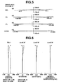
- Fig. 4 illustrates longitudinal aberration diagrams of the zoom lens at an F-drop point, which will be described later, according to the first exemplary embodiment of the present invention in the case where focusing is performed on an infinitely distant object.
- Fig. 5 illustrates lateral aberration diagrams of the zoom lens at the F-drop point according to the first exemplary embodiment of the present invention in the case where focusing is performed on an infinitely distant object.
- Fig. 6 illustrates longitudinal aberration diagrams of the zoom lens at the telephoto end according to the first exemplary embodiment of the present invention in the case where focusing is performed on an infinitely distant object.
- Fig. 7 illustrates lateral aberration diagrams of the zoom lens at the telephoto end according to the first exemplary embodiment of the present invention in the case where focusing is performed on an infinitely distant object.
- Fig. 8 is a cross-sectional view of a zoom lens according to a second exemplary embodiment of the present invention in the case where focusing is performed on an infinitely distant object.
- Fig. 9 illustrates longitudinal aberration diagrams of the zoom lens at the wide-angle end according to the second exemplary embodiment of the present invention in the case where focusing is performed on an infinitely distant object.
- Fig. 10 illustrates lateral aberration diagrams of the zoom lens at the wide-angle end according to the second exemplary embodiment of the present invention in the case where focusing is performed on an infinitely distant object.
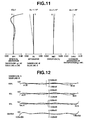
- Fig. 11 illustrates longitudinal aberration diagrams of the zoom lens at an F-drop point according to the second exemplary embodiment of the present invention in the case where focusing is performed on an infinitely distant object.
- Fig. 12 illustrates lateral aberration diagrams of the zoom lens at the F-drop point according to the second exemplary embodiment of the present invention in the case where focusing is performed on an infinitely distant object.
- Fig. 13 illustrates longitudinal aberration diagrams of the zoom lens at the telephoto end according to the second exemplary embodiment of the present invention in the case where focusing is performed on an infinitely distant object.
- Fig. 14 illustrates lateral aberration diagrams of the zoom lens at the telephoto end according to the second exemplary embodiment of the present invention in the case where focusing is performed on an infinitely distant object.
- Fig. 15 is a cross-sectional view of a zoom lens according to a third exemplary embodiment of the present invention in the case where focusing is performed on an infinitely distant object.
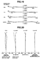
- Fig. 16 illustrates longitudinal aberration diagrams of the zoom lens at a wide-angle end according to the third exemplary embodiment of the present invention in the case where focusing is performed on an infinitely distant object.
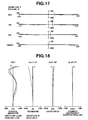
- Fig. 17 illustrates lateral aberration diagrams of the zoom lens at the wide-angle end according to the third exemplary embodiment of the present invention in the case where focusing is performed on an infinitely distant object.
- Fig. 18 illustrates longitudinal aberration diagrams of the zoom lens at an F-drop point according to the third exemplary embodiment of the present invention in the case where focusing is performed on an infinitely distant object.
- Fig. 19 illustrates lateral aberration diagrams of the zoom lens at the F-drop point according to the third exemplary embodiment of the present invention in the case where focusing is performed on an infinitely distant object.
- Fig. 20 illustrates longitudinal aberration diagrams of the zoom lens at the telephoto end according to the third exemplary embodiment of the present invention in the case where focusing is performed on an infinitely distant object.
- Fig. 21 illustrates lateral aberration diagrams of the zoom lens at the telephoto end according to the third exemplary embodiment of the present invention in the case where focusing is performed on an infinitely distant object.
- Fig. 22 is a cross-sectional view of a zoom lens according to a fourth exemplary embodiment of the present invention in the case where focusing is performed on an infinitely distant object.
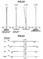
- Fig. 23 illustrates longitudinal aberration diagrams of the zoom lens at the wide-angle end according to the fourth exemplary embodiment of the present invention in the case where focusing is performed on an infinitely distant object.
- Fig. 24 illustrates lateral aberration diagrams of the zoom lens at the wide-angle end according to the fourth exemplary embodiment of the present invention in the case where focusing is performed on an infinitely distant object.
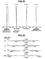
- Fig. 25 illustrates longitudinal aberration diagrams of the zoom lens at an F-drop point according to the fourth exemplary embodiment of the present invention in the case where focusing is performed on an infinitely distant object.
- Fig. 26 illustrates lateral aberration diagrams of the zoom lens at the F-drop point according to the fourth exemplary embodiment of the present invention in the case where focusing is performed on an infinitely distant object.
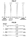
- Fig. 27 illustrates longitudinal aberration diagrams of the zoom lens at the telephoto end according to the fourth exemplary embodiment of the present invention in the case where focusing is performed on an infinitely distant object.
- Fig. 28 illustrates lateral aberration diagrams of the zoom lens at the telephoto end according to the fourth exemplary embodiment of the present invention in the case where focusing is performed on an infinitely distant object.
- Fig. 29 is a cross-sectional view of a zoom lens according to a fifth exemplary embodiment of the present invention in the case where focusing is performed on an infinitely distant object.
- Fig. 30 illustrates longitudinal aberration diagrams of the zoom lens at the wide-angle end according to the fifth exemplary embodiment of the present invention in the case where focusing is performed on an infinitely distant object.
- Fig. 31 illustrates lateral aberration diagrams of the zoom lens at the wide-angle end according to the fifth exemplary embodiment of the present invention in the case where focusing is performed on an infinitely distant object.
- Fig. 32 illustrates longitudinal aberration diagrams of the zoom lens at an F-drop point according to the fifth exemplary embodiment of the present invention in the case where focusing is performed on an infinitely distant object.
- Fig. 33 illustrates lateral aberration diagrams of the zoom lens at the F-drop point according to the fifth exemplary embodiment of the present invention in the case where focusing is performed on an infinitely distant object.
- Fig. 34 illustrates longitudinal aberration diagrams of the zoom lens at the telephoto end according to the fifth exemplary embodiment of the present invention in the case where focusing is performed on an infinitely distant object.
- Fig. 35 illustrates lateral aberration diagrams of the zoom lens at the telephoto end according to the fifth exemplary embodiment of the present invention in the case where focusing is performed on an infinitely distant object.
- Fig. 36 is a cross-sectional view of a diffractive optical element of a single-layer structure according to an exemplary embodiment of the present invention.
- Fig. 37 illustrates the wavelength dependency of the diffraction efficiency of the diffractive optical element of a single-layer structure according to an exemplary embodiment of the present invention.
- Fig. 38 is a cross-sectional view of a diffractive optical element having a laminated structure according to an exemplary embodiment of the present invention.
- Fig. 39 illustrates wavelength dependency of the diffraction efficiency of the diffractive optical element of the laminated structure according to an exemplary embodiment of the present invention.
- Fig. 40 is a cross-sectional view of a diffractive optical element according to an exemplary embodiment of the present invention.
- Fig. 41 illustrates an image pickup apparatus according to an exemplary embodiment of the present invention.
- a zoom lens includes, in order from an object side to an image side, a first lens unit F having a positive refractive power configured to be stationary during zooming, a second lens unit (variator lens unit for varying magnification) V having a negative refractive power configured to monotonically move towards the image side during zooming from a wide-angle end (short focal length end) to a telephoto end (long focal length end), a third lens unit C having a positive refractive power, including a diffractive optical element, configured to monotonically move towards the object side during zooming to compensate for variation of an image plane due to magnification variation, and a fourth lens unit R having a positive refractive power configured to be stationary during zooming and to form an image.
- the first lens unit and the fourth lens unit are stationary during zooming. This means that the first lens unit and the fourth lens unit do not move for zooming (to perform zooming). That is, during zooming, the first lens unit and the fourth lens unit can move for the purpose of performing focusing, simultaneously with zooming, or for other reasons.
- Fig. 1 is a cross-sectional view of a zoom lens at the wide-angle end of the zooming range according to a first exemplary embodiment of the present invention.
- Fig. 2 illustrates longitudinal aberration diagrams of the zoom lens at the wide-angle end according to the first exemplary embodiment of the present invention in the case where focusing is performed on an infinitely distant object.
- Fig. 3 illustrates lateral aberration diagrams of the zoom lens at the wide-angle end according to the first exemplary embodiment of the present invention in such a case.
- Fig. 4 illustrates longitudinal aberration diagrams of the zoom lens at an F-drop point according to the first exemplary embodiment of the present invention in the case where focusing is performed on an infinitely distant object.
- Fig. 5 illustrates lateral aberration diagrams of the zoom lens at the F-drop point according to the first exemplary embodiment of the present invention in such a case.
- Fig. 6 illustrates longitudinal aberration diagrams of the zoom lens at the telephoto end of the zooming range according to the first exemplary embodiment of the present invention in the case where focusing is performed on an infinitely distant object.
- Fig. 7 illustrates lateral aberration diagrams of the zoom lens at the telephoto end according to the first exemplary embodiment of the present invention in such a case.
- Fig. 8 is a cross-sectional view of a zoom lens at the wide-angle end of the zooming range according to a second exemplary embodiment of the present invention.
- Fig. 9 illustrates longitudinal aberration diagrams of the zoom lens at the wide-angle end according to the second exemplary embodiment of the present invention in the case where focusing is performed on an infinitely distant object.
- Fig. 10 illustrates lateral aberration diagrams of the zoom lens at the wide-angle end according to the second exemplary embodiment of the present invention in such a case.
- Fig. 11 illustrates longitudinal aberration diagrams of the zoom lens at an F-drop point according to the second exemplary embodiment of the present invention in the case where focusing is performed on an infinitely distant object.
- Fig. 12 illustrates lateral aberration diagrams of the zoom lens at the F-drop point according to the second exemplary embodiment of the present invention in such a case.
- Fig. 13 illustrates longitudinal aberration diagrams of the zoom lens at the telephoto end of the zooming range according to the second exemplary embodiment of the present invention in the case where focusing is performed on an infinitely distant object.
- Fig. 14 illustrates lateral aberration diagrams of the zoom lens at the telephoto end according to the second exemplary embodiment of the present invention in such a case.
- Fig. 15 is a cross-sectional view of a zoom lens at the wide-angle end of the zooming range according to a third exemplary embodiment of the present invention.
- Fig. 16 illustrates longitudinal aberration diagrams of the zoom lens at the wide-angle end according to the third exemplary embodiment of the present invention in the case where focusing is performed on an infinitely distant object.
- Fig. 17 illustrates lateral aberration diagrams of the zoom lens at the wide-angle end according to the third exemplary embodiment of the present invention in such a case.
- Fig. 18 illustrates longitudinal aberration diagrams of the zoom lens at an F-drop point according to the third exemplary embodiment of the present invention in the case where focusing is performed on an infinitely distant object.
- Fig. 19 illustrates lateral aberration diagrams of the zoom lens at the F-drop point according to the third exemplary embodiment of the present invention in such a case.
- Fig. 20 illustrates longitudinal aberration diagrams of the zoom lens at the telephoto end of the zooming range according to the third exemplary embodiment of the present invention in the case where focusing is performed on an infinitely distant object.
- Fig. 21 illustrates lateral aberration diagrams of the zoom lens at the telephoto end according to the third exemplary embodiment of the present invention in such a case.
- Fig. 22 is a cross-sectional view of a zoom lens at the wide-angle end of the zooming range according to a fourth exemplary embodiment of the present invention.
- Fig. 23 illustrates longitudinal aberration diagrams of the zoom lens at the wide-angle end according to the fourth exemplary embodiment of the present invention in the case where focusing is performed on an infinitely distant object.
- Fig. 24 illustrates lateral aberration diagrams of the zoom lens at the wide-angle end according to the fourth exemplary embodiment of the present invention in such a case.
- Fig. 25 illustrates longitudinal aberration diagrams of the zoom lens at an F-drop point according to the fourth exemplary embodiment of the present invention in the case where focusing is performed on an infinitely distant object.
- Fig. 26 illustrates lateral aberration diagrams of the zoom lens at the F-drop point according to the fourth exemplary embodiment of the present invention in such a case.
- Fig. 27 illustrates longitudinal aberration diagrams of the zoom lens at the telephoto end of the zooming range according to the fourth exemplary embodiment of the present invention in the case where focusing is performed on an infinitely distant object.
- Fig. 28 illustrates lateral aberration diagrams of the zoom lens at the telephoto end according to the fourth exemplary embodiment of the present invention in such a case.
- Fig. 29 is a cross-sectional view of a zoom lens at the wide-angle end of the zooming range according to a fifth exemplary embodiment of the present invention.
- Fig. 30 illustrates longitudinal aberration diagrams of the zoom lens at the wide-angle end according to the fifth exemplary embodiment of the present invention in the case where focusing is performed on an infinitely distant object.
- Fig. 31 illustrates lateral aberration diagrams of the zoom lens at the wide-angle end according to the fifth exemplary embodiment of the present invention in such a case.
- Fig. 32 illustrates longitudinal aberration diagrams of the zoom lens at an F-drop point according to the fifth exemplary embodiment of the present invention in the case where focusing is performed on an infinitely distant object.
- Fig. 33 illustrates lateral aberration diagrams of the zoom lens at the F-drop point according to the fifth exemplary embodiment of the present invention in such a case.
- Fig. 34 illustrates longitudinal aberration diagrams of the zoom lens at the telephoto end according to the fifth exemplary embodiment of the present invention in the case where focusing is performed on an infinitely distant object.
- Fig. 35 illustrates lateral aberration diagrams of the zoom lens at the telephoto end according to the fifth exemplary embodiment of the present invention in such a case.
- Fig. 36 is a cross-sectional view of a diffractive optical element according to an exemplary embodiment of the present invention.
- Fig. 37 illustrates wavelength dependency of a diffraction efficiency of the diffractive optical element according to an exemplary embodiment of the present invention.
- Fig. 38 is a cross-sectional view of a diffractive optical element according to an exemplary embodiment of the present invention.
- Fig. 39 illustrates wavelength dependency of a diffraction efficiency of this diffractive optical element according to an exemplary embodiment of the present invention.
- Fig. 40 is a cross-sectional view of a diffractive optical element according to an exemplary embodiment of the present invention.
- Fig. 41 schematically illustrates an image pickup apparatus according to an exemplary embodiment of the present invention.
- the first lens unit F having a positive refractive power is stationary during zooming
- the second lens unit (variator lens unit for varying magnification) V having a negative refractive power is movable during zooming
- the third lens unit(compensator lens unit) C having a positive refractive power for compensating for variation of an image plane due to magnification variation is movable during zooming.
- An aperture stop SP is located at the image side of the third lens unit C.
- the fourth lens unit (relay lens unit) R serves to form an image of an object.
- a glass block G serves as a color separation prism or an optical filter.
- An image plane IP corresponds to an imaging plane of a solid-state image sensor (photoelectric conversion element).
- curves g and e represent g-line and e-line light, respectively.
- Curves M and S correspond to a meridional image plane and a sagittal image plane, respectively.
- Chromatic aberration of magnification is represented with g-line light.
- the Y-axis in the spherical aberration's graph represents an entrance pupil radius at a predetermined f-number Fno.
- the Y-axis in the astigmatism's, distortion's and chromatic aberration of magnification's graphs represents an image height at a predetermined half angle of view ⁇ .
- the abscissa axis indicating spherical aberration is represented with a scale of 0.4 mm.
- the abscissa axis indicating astigmatism is represented with a scale of 0.4 mm.
- the abscissa axis indicating distortion is represented with a scale of 10%.
- the abscissa axis indicating lateral aberration is represented with a scale of 0.1 mm.
- the terms "wide-angle end” and “telephoto end” designate zoom positions respectively corresponding to both ends of a range in which the second lens unit V for varying magnification can mechanically move along an optical axis.
- the first lens unit F has a refractive power for focusing. Focusing is performed by moving a lens unit F' having a refractive power, which can be either the whole first lens unit or only a part of the first lens unit F.
- focusing from an infinitely distant object up to a short distant object is performed by moving the lens unit F' , which is a part of the first lens unit F, to the object side.
- focusing from an infinitely distant object up to a short distant object is performed by moving the entire first lens unit F (the lens unit F') to the object side.
- the second lens unit V moves monotonically towards the image side along the optical axis, as indicated by an arrow, to vary magnification from a wide-angle end to a telephoto end.
- the third lens unit C moves in a non-linear fashion towards the object side, as indicated by an arrow, when magnification is changed from a wide-angle end to a telephoto end. Thus, variation of an image plane due to magnification variation is compensated for.
- the second lens unit V and the third lens unit C constitute a magnification variation lens unit (magnification variation portion).
- the distance between the second lens unit V and the third lens unit C decreases during zooming from the wide-angle end to the telephoto end.
- Both the second lens unit V and the third lens unit C simultaneously use a zoom area in which an image-forming magnification of (-1) (equi-magnification) is included.
- both the second lens unit V and the third lens unit C can greatly contribute to the variation of magnification.
- a high zoom ratio of 40 or more can be achieved at a small movement distance of the lens units V and C.
- the zoom lens of the above-described zooming type is permitted to reduce F-number at a zoom position corresponding to the telephoto end thereof so as to reduce the size of the entire lens system.
- a focal position or focal length
- F-drop point a focal position at which the F-number starts to decrease, in a zooming range
- the lens unit F does not move to perform zooming.
- the second lens unit V moves monotonically towards the object side
- the third lens unit C moves towards the object side.
- an on-axis light ray and an off-axis light ray, which are incident on the third lens unit C change in the following manner during zooming.
- the height of an axial marginal light ray, which is incident on the third lens unit C, is gradually increased, as the distance between the second lens unit V and the third lens unit C is decreased during zooming from the wide-angle end to the telephoto end.
- the height of the axial marginal light ray has a maximum value at the F-drop point. Subsequently, as the zoom lens is focused to a further telephoto end side, the height of the axial marginal light ray gradually decreases.
- axial chromatic aberration and spherical aberration have a tendency towards extreme deterioration in the vicinity of the F-drop point. Additionally, in a range from the F-drop point to the telephoto end, the magnification varying rate increases markedly. Thus, axial chromatic aberration and spherical aberration have a tendency towards further deterioration.
- the third lens unit C does not move much away from the stop SP.
- the height of an off-axis marginal light ray, which forms an image at a maximum image height is small.
- the effect of the third lens unit C on chromatic aberration of magnification among various kinds of chromatic aberration over the entire zooming range is relatively low, as compared with the other lens units.
- the third lens unit C greatly affects variation of halo and coma aberration in addition to the variation of spherical aberration.
- the lens configuration of the third lens unit C for example, the shape and the refractive power (optical power) of each of lens elements of the third lens unit C.
- the lens elements constituting the third lens unit C include at least one or more positive lenses, one or more negative lens, and one or more diffractive optical elements, and satisfy the following conditions.
- a focal length (fc) of the third lens unit C, a focal length (fdoe) of the diffractive optical element, a focal length (fW) at the wide angle end of the entire zoom lens, and a focal length (fT) at the telephoto end thereof satisfy the following conditions: 0.35 ⁇ fc / W • T ⁇ 0.81 and 45 ⁇ fdoe / fc ⁇ 300
- the "diffraction portion” in each exemplary embodiment designates one or more diffractive gratings provided on a substrate (flat plate or lens).
- the "diffractive optical element” designates an element obtained by providing a diffraction portion including one or more diffraction gratings on a substrate (flat plate or lens).
- ⁇ d designates a reference wavelength (d-line light)
- h designates a distance from an optical axis
- ⁇ (h)” denotes a phase
- "i” represents a natural number.
- the refractive power ⁇ D of the diffraction portion is obtained by quadratic approximation.
- the lens elements constituting the third lens unit C do not include one or more positive lenses and one or more negative lenses, a burden of aberration correction to be placed on each single lens element is increased. Consequently, even in a case where anomalous dispersion glass, an aspherical optical element, or a diffractive optical element is used, it is difficult to eliminate the factors contributing to the deterioration of various aberrations.
- the refractive power of the third lens unit C is too small.
- the total length of the zoom lens is too long.
- the refractive power of the third lens unit C is too large. Spherical aberration is increased in the vicinity of the above-described F-drop point and at the telephoto end. Moreover, it is difficult to correct spherical aberration due to zooming, halo and coma aberration.
- the condition (2) regulates the power of the diffraction portion of the diffractive optical element of the third lens unit C within an appropriate range with respect to the focal length of the third lens unit C.
- These glass materials have small refractive indexes. Thus, it is difficult to correct the variation of aberration due to zooming other than the above-described chromatic aberrations over the zooming range. Particularly, it is difficult to configure the third lens unit C such that the third lens unit C provides an appropriate refractive power within a range according to the condition (1).
- axial chromatic aberration caused by an optical system including a diffractive optical element is represented by the following expressions in a case where the optical system is constituted by thin optical elements:
- L 1 / fp • vpe + 1 / fn • vne + 1 / fdoe • vdo ⁇ 2
- the value of the axial chromatic aberration coefficient is small.
- the refractive power of the positive lens and that of the negative lens are uniquely determined by once selecting Abbe numbers of the materials of the positive lens and the negative lens.
- the diffraction portion has a negative dispersion value whose absolute value is large.
- the glass materials of the refractive optical components are more flexibly selected by setting the diffraction portion to have a positive refractive power. Consequently, the optical system, whose chromatic aberration and Seidel aberration typified by chromatic aberration is optimally corrected, can be implemented without increasing the number of optical elements of the optical system.
- the dispersion value of the material of the diffraction portion is -3.2, in comparison with the dispersion value of ordinary glass, which ranges from 15 to 100. That is, the dispersion value of the material of the diffraction portion differs from that of ordinary glass in sign by one order of magnitude of the absolute value.
- very large inverse correction capability acts, so that the correction is excessive in a case where the power is large.
- the optical system in each exemplary embodiment uses wavelengths of the entire visible light region. Thus, it is necessary to take the correction of chromatic aberration for all wavelengths of the visible light region into consideration.
- the state of light rays incident on a lens unit is changed according to zooming.
- it is necessary to consider the balance among various aberrations in the entire zooming range of the entire optical system.
- the significance of the assignment of aberration to each of the lens units constituting the zoom lens depends upon the lens units.
- the conditions (1) and (2) are set to optimize the power of the third lens unit C including the diffraction portion and the power of the diffraction portion according to the zooming type of the zoom lens in each exemplary embodiment.
- a compact zoom lens having a high zoom ratio and a large aperture ratio can be configured by locating a diffractive optical element in the third lens unit C, which moves towards the object side during zooming, at a place closer to the image side than the second lens unit V for varying magnification in a positive-lead type zoom lens.
- a large-aperture-ratio and high-zoom-ratio zoom lens which has an F-number of 1.5 to 1.8 and a zoom ratio of 40 or more, can be obtained.
- the refractive power of the third lens unit C is too small.
- the magnification (or zoom ratio) assigned to the lens unit located closer to the image side than the third lens unit C is too large. Consequently, the configuration of the lens unit located closer to the image side than the third lens unit C is complex. In each case, the total length of the zoom lens is large.
- the refractive power of the third lens unit C is too large.
- the magnification (or zoom ratio) assigned to the lens unit located closer to the image side than the third lens unit C is too small. Therefore, the aberration to be corrected by the second lens unit (zooming lens unit) V becomes large. Consequently, the variation of aberration, which is caused by the movement of the second lens unit V or the third lens unit C for zooming, is increased or deteriorated. Also, the size of the second lens unit V or the third lens unit C is increased.
- the condition (4) is determined for appropriately setting a ratio of the focal length of the diffraction portion of the diffractive optical element to the focal length of the entire lens system at the telephoto end.
- low-dispersion glass has a tendency towards a low refractive index.
- it is difficult to reduce the variation of spherical aberration, halo, and coma aberration due to zooming.
- the total length of the zoom lens increases.
- the mean dispersion of the material of positive lenses included in the third lens unit C is high, so that the power of the diffraction portion is too large.
- axial chromatic aberration is excessively corrected over the entire zooming range.
- the condition (8) defines the range of a part of the lateral magnification, which is assigned to the third lens unit C, due to zooming. More particularly, the condition (8) appropriately defines a proportion of a change in the lateral magnification of the third lens unit C, which is caused by zooming from the wide-angle end to the telephoto end, to an average lateral magnification of the lens unit C.
- the change in the lateral magnification of the third lens unit C which is caused by zooming from the wide-angle end to the telephoto end, is larger than the average lateral magnification of the lens unit C, so that the aberration correction capability of the third lens unit C is higher than that of the other lens units over the entire zooming range.
- the lens configuration of the third lens unit C is complicated. Unless the number of elements of the lens unit C is increased, which is not desirable, it is difficult to correct the variation of, for example, spherical aberration, halo, and coma aberration.
- the change in the lateral magnification of the third lens unit C which is caused by zooming from the wide-angle end to the telephoto end, is smaller than the average lateral magnification of the lens unit C, so that a proportion of the lateral magnification, which is assigned to the third lens unit C, is too small. Consequently, a proportion of the lateral magnification, which is assigned to the other lens units, is large.
- the stroke lengths of the other magnification varying lens units are increased.
- the total length of the zoom lens is thus increased.
- a burden of aberration correction to be placed on the other lens units is increased. Consequently, the number of constituent elements of the other lens units should be increased. Accordingly, the total length of the zoom lens is increased.
- the condition (9) relates to a pitch of a diffractive pattern of the diffraction portion.
- the diffractive optical element is appropriately used in a part of the zoom lens. Consequently, a zoom lens, which has a large aperture ratio, a high zoom ratio, and good optical performance over the entire zooming range and which is suitable for use with, for example, a television camera, a video camera, and a photographing camera, can be obtained.
- the numerical ranges to be defined by the conditions (3) to (9) can be set as follows: 0.65 ⁇ fc • ⁇ RT / W • T ⁇ 0.85 4 ⁇ fdoe / fT ⁇ 25 0.017 ⁇ 1 / vcp ⁇ ave ⁇ 0.026 0.013 ⁇ 1 / vcn ⁇ ave - 1 / vcp ⁇ ave ncp ⁇ ave > 1.64 1.5 ⁇ ⁇ cW • ⁇ cT / ⁇ cT • ⁇ cW ⁇ 2.3 50 ⁇ fdoe / D ⁇ 230
- the lens elements constituting the third lens unit C can include at least three or more positive lenses, one or more negative lenses, and one diffractive optical element.
- the third lens unit C can include two or more positive lenses, at least one of the surfaces of which is an aspheric surface.
- the third lens unit C can have an appropriate number of optical elements. Also, because at least one of surfaces of the elements of the third lens unit C is an aspheric surface, a capability of the third lens unit to correct the variation of various aberrations occurring due to zooming can be enhanced. Additionally, a high-zoom-ratio zoom lens, the size of the entire system of which is compact, can be achieved by increasing a proportion of the magnification, which is assigned to the third lens unit C.
- the diffraction portion itself can have an advantage of an aspherical surface. This is achieved by giving values to a coefficient C4 of a bi-quadratic term and coefficients of higher-order terms of a function of the distance h from the optical axis in the expression (a) representing the phase of the diffraction portion in each exemplary embodiment.
- An aperture stop SP can be located at the image side of the third lens unit C.
- the aperture stop SP is located at a place closer to the image side than a lens unit that greatly contributes to varying magnification. Consequently, an exit pupil can be always held at a fixed far-off position independent of zooming.
- the zoom lens is used in a color camera including a color separation system typified by triple prisms and a charge coupled device (CCD) or a complementary metal-oxide semiconductor (CMOS) device, the characteristic of which is changed according to an incidence angle, as an image sensor in an image pickup portion, degradation in image quality due to color shading is minimized.
- CMOS complementary metal-oxide semiconductor
- Fig. 36 is an enlarged cross-sectional view of a diffraction portion of a diffractive optical element 1.
- a diffraction grating 3 constituted by a single layer is provided on a substrate (transparent substrate) 2.
- Fig. 37 illustrates a characteristic of diffraction efficiency of the diffractive optical element 1.
- the abscissa axis represents wavelength.
- the ordinate represents a diffraction efficiency that is a proportion of an amount of diffracted light to a total amount of transmitted light flux.
- reflection light on a boundary surface of the diffraction grating is not taken into consideration.
- the grating thickness d1 is set at 1.03 ⁇ m.
- the diffraction efficiency of + first-order diffracted light having a wavelength of 530 nm is set to be highest.
- a designed order of the diffracted light corresponding to the highest diffraction efficiency is + first-order.
- a designed wavelength of the diffracted light corresponding to the highest diffraction efficiency is 530 nm.
- the diffraction efficiency of + first-order diffracted light is represented by a solid curve.
- Fig. 37 illustrates also diffraction efficiencies of diffracted light rays respectively corresponding to diffraction orders ((+ first-order ⁇ 1)-th order (i.e., 0-th order and + second-order) ) in the vicinity of the designed order.
- the diffraction efficiency at the designed order has a highest value that is obtained at a wavelength in the vicinity of the designed wavelength.
- the diffraction efficiency is gradually decreased at wavelengths other than the wavelength in the vicinity of the designed wavelength.
- Fig. 38 is an enlarged cross-sectional view of a part of such a laminated type diffractive optical element.
- Fig. 39 is a graph illustrating a wavelength dependency of the diffraction efficiency of + first-order diffracted light of the diffractive optical element illustrated in Fig. 38 .
- a thickness d1 of the first diffraction grating 104 is set at 13.8 ⁇ m.
- a thickness d2 of the second diffraction grating 105 is set at 10.5 ⁇ m.
- the material of the diffraction gratings of the diffractive optical element of the laminated structure is not limited to an ultraviolet curable resin. Other plastic materials can be used as the material of the diffraction gratings.
- the first layer can be formed directly on the base material.
- the gratings are not necessarily different in thickness from one another. As illustrated in Fig. 40 , in some combination of the materials, the thicknesses of the two layers 104 and 105 can be set to be equal to each other. In this case, no diffraction grating shapes are formed on the surface of the substrate.
- the dust-resistance of the diffractive optical element can be enhanced.
- the assemblability of the diffractive optical element can be enhanced. Additionally, it is not necessary to bring the two diffraction gratings 104 and 105 into close contact with each other.
- the two diffraction gratings 104 and 105 can be disposed to face each other across an air gap.
- the last two optical surfaces are those of a glass block, such as a filter.
- X 1 / R ⁇ H 2 / 1 + 1 - 1 + k ⁇ H / R 2 1 / 2 + AH 4 + BH 6 + CG 8 + DH 10 + EH ⁇ h 12
- X designates an X-axis extending along the optical axis
- H denotes an H-axis extending in a direction perpendicular to the optical axis
- a "positive direction” is set to be a traveling direction in which light travels
- R designates a paraxial radius of curvature
- k designates a conic constant
- each of "A”, “B”, “C”, “D”, and "E” is an aspheric coefficient corresponding to an associated order.
- the third lens unit C of the first exemplary embodiment illustrated in Fig. 1 includes four lens sub-units which have five lenses, that is, includes a positive lens (G1), a positive lens (G2), a cemented lens unit composed of a negative lens (G3) and a positive lens (G4), and a positive lens (G5) in order from the object side to the image side.
- the diffraction portion is formed on a cemented surface (27-th surface).
- the image-side surface of the positive lens G1 is an aspherical surface.
- the third lens unit C of the second exemplary embodiment illustrated in Fig. 8 includes five lens sub-units which have eight lenses, that is, includes a positive lens (G1), a positive lens (G2), a negative lens (G3), a cemented lens unit composed of a negative lens (G4) and a positive lens (G5), and a positive lens (G6) in order from the object side to the image side.
- the diffraction portion is formed on a cemented surface between the negative lens G4 and the positive lens G5 (29-th surface).
- the image-side surface of the positive lens G1 and the object-side surface of the positive lens G6 are aspherical surfaces.
- the third lens unit C of the third exemplary embodiment illustrated in Fig. 15 includes three lens sub-units which have four lenses, that is, includes a positive lens (G1), a cemented lens unit composed of a positive lens (G2) and a negative lens (G3), and a positive lens (G4) in order from the object side to the image side.
- the diffraction portion is formed on an image-side surface of the negative lens G3 (26-th surface).
- the image-side surface of the positive lens G1, the image-side surface of the positive lens G2, and the object-side surface of the positive lens G4 are aspherical surfaces.
- the third lens unit C of the fourth exemplary embodiment illustrated in Fig. 22 includes four lens sub-units which have five lenses, that is, includes a positive lens (G1), a positive lens (G2), a cemented lens unit composed of a negative lens (G3) and a positive lens (G4), and a positive lens (G5) in order from the object side to the image side.
- the diffraction portion is formed on the object-side surface of the positive lens G2 (24-th surface) .
- the image-side surface of the positive lens G2 is an aspherical surface.
- the third lens unit C of the fifth exemplary embodiment illustrated in Fig. 29 includes four lens sub-units which have six lenses, that is, includes a positive lens (G1), a cemented lens unit composed of a negative lens (G2) and a positive lens (G3), a cemented lens unit composed of a positive lens (G4) and a negative lens (G5), and a positive lens (G6) in order from the object side to the image side.
- the diffraction portion is formed on the object-side surface of the positive lens G4 (21-th surface).
- the image-side surface of the positive lens G1 is an aspherical surface.
- chromatic aberration is corrected well from the wide-angle end to the telephoto end, although relatively high-dispersion glass is used as the material of positive lenses of the third lens unit C.
- the diffraction portion is formed on a surface convex towards the object side.
- a positive lens is located at a place closer to the object side than the diffraction portion.
- Each exemplary embodiment utilizes aspherical surfaces.
- a zoom lens which causes minimal variation of spherical aberration, halo, and coma aberration, is achieved by adding an aspherical surface to the configuration thereof in addition to the utilization of the relatively high-refractive index material as the positive lenses and the aspheric effects of the diffraction portion.
- the first exemplary embodiment is a zoom lens that has a zoom ratio of 81, in which an angle of view at a wide-angle end is 57° and an angle of view at a telephoto end is 0.78°.
- the second exemplary embodiment is a zoom lens that increases the zoom ratio to 100 and reduces the angle of view at a telephoto end to 0.42°, as compared with the first exemplary embodiment.
- the third embodiment is a zoom lens that has a zoom ratio of 117, in which an angle of view at a telephoto end is 0.38°.
- the fourth exemplary embodiment is a zoom lens that increases the angle of view at a wide-angle end to 69° and increases also a zoom ratio to 105, as compared with the first exemplary embodiment.
- the fifth embodiment is a zoom lens that has a zoom ratio of 44.
- Fig. 41 illustrates an image pickup apparatus (television camera system) 125 using a zoom lens in each exemplary embodiment as an image pickup optical system.
- the image pickup apparatus 125 includes a zoom lens 101 according to one of the first to fifth exemplary embodiments.
- the image pickup apparatus 125 further includes a camera 124.
- the zoom lens 101 is detachable from the camera 124.
- the image pickup apparatus 125 is constituted by mounting the zoom lens 101 on the camera 124.
- the zoom lens 101 includes a first lens unit F, a magnification variation portion LZ, a fourth lens unit R for image formation.
- the first lens unit F includes a focusing lens unit.
- the magnification variation portion LZ includes a second lens unit V configured to move along an optical axis for varying magnification, and a third lens unit C configured to move along the optical axis to compensate for variation of an image plane due to magnification variation.
- the zoom lens 101 further includes an aperture stop SP.
- the fourth lens unit R includes a lens unit 105, a glass block 106 that can be detached from an optical path, and a lens unit 107.
- the zoom lens 101 further includes an extender EX serving as a lens unit that can be replaced with the glass block 106 to change a focal length range of the entire zoom lens 101.
- the zoom lens 101 further includes drive mechanisms 114 and 115, such as a helicoid and a cam, for driving the lens unit F and the magnification variation portion LZ, respectively.
- the zoom lens 101 further includes electric motors (drive units) 116, 117, and 118 configured to drive the drive mechanisms 114 and 115 and the aperture stop SP, respectively.
- electric motors drive units
- the zoom lens 101 further includes detectors 119, 120, and 121, such as an encoder, a potentiometer, and a photosensor, configured to detect the positions of the first lens unit F and the magnification variation portion LZ on the optical axis and an aperture diameter of the aperture stop SP, respectively.
- detectors 119, 120, and 121 such as an encoder, a potentiometer, and a photosensor, configured to detect the positions of the first lens unit F and the magnification variation portion LZ on the optical axis and an aperture diameter of the aperture stop SP, respectively.
- the camera 124 includes a glass block 109, which corresponds to an optical filter and a color separation prism, and a solid-state image sensor (photoelectric conversion element) 110, such as a CCD sensor or a CMOS sensor, for receiving an image of an object formed by the zoom lens 101.
- a solid-state image sensor photoelectric conversion element 110
- CCD sensor or a CMOS sensor
- Central processing units (CPU) 111 and 122 control various operations of driving the camera 124 and the zoom lens 101, respectively.
- an image pickup apparatus having high optical performance is implemented by applying the zoom lens according to an exemplary embodiment of the present invention to a television camera.
- a zoom lens having high optical performance over the entire zooming range and an image pickup apparatus having such a zoom lens can be obtained.
Landscapes
- Physics & Mathematics (AREA)
- General Physics & Mathematics (AREA)
- Optics & Photonics (AREA)
- Lenses (AREA)
Applications Claiming Priority (1)
| Application Number | Priority Date | Filing Date | Title |
|---|---|---|---|
| JP2007034759A JP5028103B2 (ja) | 2007-02-15 | 2007-02-15 | ズームレンズ及びそれを有する撮像装置 |
Publications (3)
| Publication Number | Publication Date |
|---|---|
| EP1959286A2 EP1959286A2 (en) | 2008-08-20 |
| EP1959286A3 EP1959286A3 (en) | 2012-01-25 |
| EP1959286B1 true EP1959286B1 (en) | 2013-04-10 |
Family
ID=39471997
Family Applications (1)
| Application Number | Title | Priority Date | Filing Date |
|---|---|---|---|
| EP08151283.2A Not-in-force EP1959286B1 (en) | 2007-02-15 | 2008-02-11 | Zoom lens and image pickup apparatus having the same |
Country Status (3)
| Country | Link |
|---|---|
| US (1) | US7583449B2 (enExample) |
| EP (1) | EP1959286B1 (enExample) |
| JP (1) | JP5028103B2 (enExample) |
Families Citing this family (8)
| Publication number | Priority date | Publication date | Assignee | Title |
|---|---|---|---|---|
| JP5178798B2 (ja) | 2010-09-15 | 2013-04-10 | キヤノン株式会社 | ズームレンズ及びそれを有する撮像装置 |
| JP5656684B2 (ja) * | 2011-02-28 | 2015-01-21 | キヤノン株式会社 | ズームレンズ及びそれを有する撮像装置 |
| CN103477266B (zh) * | 2011-04-06 | 2016-12-28 | 株式会社尼康 | 变焦光学系统及具有其的拍摄装置 |
| JP6245507B2 (ja) | 2013-09-11 | 2017-12-13 | 株式会社リコー | ズームレンズ、カメラおよび携帯情報端末装置 |
| CN104199178B (zh) * | 2014-08-06 | 2017-03-29 | 青岛歌尔声学科技有限公司 | 一种变焦镜头 |
| JP6670262B2 (ja) * | 2017-02-24 | 2020-03-18 | 富士フイルム株式会社 | ズームレンズおよび撮像装置 |
| US10495847B2 (en) * | 2017-09-20 | 2019-12-03 | Young Optics Inc. | Zoom lens |
| CN111308660B (zh) * | 2020-03-16 | 2025-05-09 | 江西欧菲光学有限公司 | 光学系统、摄像模组及电子装置 |
Family Cites Families (5)
| Publication number | Priority date | Publication date | Assignee | Title |
|---|---|---|---|---|
| US5268790A (en) | 1991-12-20 | 1993-12-07 | Hughes Aircraft Company | Zoom lens employing refractive and diffractive optical elements |
| US6606200B1 (en) * | 1996-09-19 | 2003-08-12 | Canon Kabushiki Kaisha | Zoom lens device and optical apparatus provided with the same |
| JP3990025B2 (ja) * | 1998-03-24 | 2007-10-10 | オリンパス株式会社 | ズームレンズ |
| JP4273556B2 (ja) * | 1999-02-08 | 2009-06-03 | コニカミノルタオプト株式会社 | レンズ光学系 |
| JP4004140B2 (ja) | 1998-04-30 | 2007-11-07 | オリンパス株式会社 | 回折光学素子を用いたズームレンズ及びそれを用いた撮像装置 |
-
2007
- 2007-02-15 JP JP2007034759A patent/JP5028103B2/ja not_active Expired - Fee Related
-
2008
- 2008-02-11 EP EP08151283.2A patent/EP1959286B1/en not_active Not-in-force
- 2008-02-12 US US12/030,111 patent/US7583449B2/en not_active Expired - Fee Related
Also Published As
| Publication number | Publication date |
|---|---|
| EP1959286A2 (en) | 2008-08-20 |
| JP2008197533A (ja) | 2008-08-28 |
| EP1959286A3 (en) | 2012-01-25 |
| JP5028103B2 (ja) | 2012-09-19 |
| US20080291546A1 (en) | 2008-11-27 |
| US7583449B2 (en) | 2009-09-01 |
Similar Documents
| Publication | Publication Date | Title |
|---|---|---|
| US7885014B2 (en) | Zoom lens system and image pickup apparatus including the same | |
| JP4810133B2 (ja) | ズームレンズ及びそれを有する撮像装置 | |
| EP3534197B1 (en) | Zoom lens and image pickup apparatus | |
| JP4928297B2 (ja) | ズームレンズ及びそれを有する撮像装置 | |
| EP2541297B1 (en) | Zoom lens of the telephoto type and having four lens groups | |
| EP2650712B1 (en) | Zoom lens of the telephoto type having four lens groups | |
| US9244259B2 (en) | Zoom lens and image pickup apparatus including the same | |
| EP2650711B1 (en) | Zoom lens of the telephoto type having four lens groups | |
| EP2026113B1 (en) | Zoom lens of the telephoto type having four lens groups | |
| US10908388B2 (en) | Zoom lens, optical apparatus, and method for manufacturing zoom lens | |
| US8149516B2 (en) | Zoom lens with high optical performance throughout entire zoom range and image pickup apparatus having the same | |
| EP2287650B1 (en) | Zoom lens and image pickup apparatus equipped with same | |
| CN108398773B (zh) | 变焦透镜和具有变焦透镜的图像拾取装置 | |
| US20150042846A1 (en) | Zoom lens and image pickup apparatus having the same | |
| EP2287649A1 (en) | Zoom lens system and image pickup apparatus including the same | |
| EP1959286B1 (en) | Zoom lens and image pickup apparatus having the same | |
| EP2023178B1 (en) | Zoom lens of the telephoto type and having four lens groups | |
| US7289280B2 (en) | Zoom lens and imaging system | |
| CN112394499B (zh) | 变焦镜头和摄像设备 | |
| JP6808441B2 (ja) | ズームレンズ及びそれを有する撮像装置 | |
| US20200018937A1 (en) | Zoom lens and image pickup apparatus | |
| US7426083B2 (en) | Imaging optical system and image capturing apparatus including imaging optical system | |
| JP2009098419A (ja) | コンバータレンズ及びそれを有するズームレンズ | |
| JP5656684B2 (ja) | ズームレンズ及びそれを有する撮像装置 | |
| US6141157A (en) | Zoom lens |
Legal Events
| Date | Code | Title | Description |
|---|---|---|---|
| PUAI | Public reference made under article 153(3) epc to a published international application that has entered the european phase |
Free format text: ORIGINAL CODE: 0009012 |
|
| AK | Designated contracting states |
Kind code of ref document: A2 Designated state(s): AT BE BG CH CY CZ DE DK EE ES FI FR GB GR HR HU IE IS IT LI LT LU LV MC MT NL NO PL PT RO SE SI SK TR |
|
| AX | Request for extension of the european patent |
Extension state: AL BA MK RS |
|
| PUAL | Search report despatched |
Free format text: ORIGINAL CODE: 0009013 |
|
| AK | Designated contracting states |
Kind code of ref document: A3 Designated state(s): AT BE BG CH CY CZ DE DK EE ES FI FR GB GR HR HU IE IS IT LI LT LU LV MC MT NL NO PL PT RO SE SI SK TR |
|
| AX | Request for extension of the european patent |
Extension state: AL BA MK RS |
|
| RIC1 | Information provided on ipc code assigned before grant |
Ipc: G02B 15/173 20060101AFI20111219BHEP |
|
| 17P | Request for examination filed |
Effective date: 20120725 |
|
| AKX | Designation fees paid |
Designated state(s): AT BE BG CH CY CZ DE DK EE ES FI FR GB GR HR HU IE IS IT LI LT LU LV MC MT NL NO PL PT RO SE SI SK TR |
|
| GRAP | Despatch of communication of intention to grant a patent |
Free format text: ORIGINAL CODE: EPIDOSNIGR1 |
|
| GRAS | Grant fee paid |
Free format text: ORIGINAL CODE: EPIDOSNIGR3 |
|
| GRAA | (expected) grant |
Free format text: ORIGINAL CODE: 0009210 |
|
| AK | Designated contracting states |
Kind code of ref document: B1 Designated state(s): AT BE BG CH CY CZ DE DK EE ES FI FR GB GR HR HU IE IS IT LI LT LU LV MC MT NL NO PL PT RO SE SI SK TR |
|
| REG | Reference to a national code |
Ref country code: GB Ref legal event code: FG4D |
|
| REG | Reference to a national code |
Ref country code: AT Ref legal event code: REF Ref document number: 606305 Country of ref document: AT Kind code of ref document: T Effective date: 20130415 Ref country code: CH Ref legal event code: EP |
|
| REG | Reference to a national code |
Ref country code: IE Ref legal event code: FG4D |
|
| REG | Reference to a national code |
Ref country code: DE Ref legal event code: R096 Ref document number: 602008023621 Country of ref document: DE Effective date: 20130606 |
|
| REG | Reference to a national code |
Ref country code: DE Ref legal event code: R082 Ref document number: 602008023621 Country of ref document: DE Representative=s name: WESER & KOLLEGEN, DE |
|
| PG25 | Lapsed in a contracting state [announced via postgrant information from national office to epo] |
Ref country code: SI Free format text: LAPSE BECAUSE OF FAILURE TO SUBMIT A TRANSLATION OF THE DESCRIPTION OR TO PAY THE FEE WITHIN THE PRESCRIBED TIME-LIMIT Effective date: 20130410 |
|
| REG | Reference to a national code |
Ref country code: AT Ref legal event code: MK05 Ref document number: 606305 Country of ref document: AT Kind code of ref document: T Effective date: 20130410 |
|
| REG | Reference to a national code |
Ref country code: LT Ref legal event code: MG4D Ref country code: NL Ref legal event code: VDEP Effective date: 20130410 |
|
| PG25 | Lapsed in a contracting state [announced via postgrant information from national office to epo] |
Ref country code: AT Free format text: LAPSE BECAUSE OF FAILURE TO SUBMIT A TRANSLATION OF THE DESCRIPTION OR TO PAY THE FEE WITHIN THE PRESCRIBED TIME-LIMIT Effective date: 20130410 Ref country code: SE Free format text: LAPSE BECAUSE OF FAILURE TO SUBMIT A TRANSLATION OF THE DESCRIPTION OR TO PAY THE FEE WITHIN THE PRESCRIBED TIME-LIMIT Effective date: 20130410 Ref country code: IS Free format text: LAPSE BECAUSE OF FAILURE TO SUBMIT A TRANSLATION OF THE DESCRIPTION OR TO PAY THE FEE WITHIN THE PRESCRIBED TIME-LIMIT Effective date: 20130810 Ref country code: BE Free format text: LAPSE BECAUSE OF FAILURE TO SUBMIT A TRANSLATION OF THE DESCRIPTION OR TO PAY THE FEE WITHIN THE PRESCRIBED TIME-LIMIT Effective date: 20130410 Ref country code: NL Free format text: LAPSE BECAUSE OF FAILURE TO SUBMIT A TRANSLATION OF THE DESCRIPTION OR TO PAY THE FEE WITHIN THE PRESCRIBED TIME-LIMIT Effective date: 20130410 Ref country code: LT Free format text: LAPSE BECAUSE OF FAILURE TO SUBMIT A TRANSLATION OF THE DESCRIPTION OR TO PAY THE FEE WITHIN THE PRESCRIBED TIME-LIMIT Effective date: 20130410 Ref country code: FI Free format text: LAPSE BECAUSE OF FAILURE TO SUBMIT A TRANSLATION OF THE DESCRIPTION OR TO PAY THE FEE WITHIN THE PRESCRIBED TIME-LIMIT Effective date: 20130410 Ref country code: PT Free format text: LAPSE BECAUSE OF FAILURE TO SUBMIT A TRANSLATION OF THE DESCRIPTION OR TO PAY THE FEE WITHIN THE PRESCRIBED TIME-LIMIT Effective date: 20130812 Ref country code: GR Free format text: LAPSE BECAUSE OF FAILURE TO SUBMIT A TRANSLATION OF THE DESCRIPTION OR TO PAY THE FEE WITHIN THE PRESCRIBED TIME-LIMIT Effective date: 20130711 Ref country code: NO Free format text: LAPSE BECAUSE OF FAILURE TO SUBMIT A TRANSLATION OF THE DESCRIPTION OR TO PAY THE FEE WITHIN THE PRESCRIBED TIME-LIMIT Effective date: 20130710 Ref country code: ES Free format text: LAPSE BECAUSE OF FAILURE TO SUBMIT A TRANSLATION OF THE DESCRIPTION OR TO PAY THE FEE WITHIN THE PRESCRIBED TIME-LIMIT Effective date: 20130721 |
|
| PG25 | Lapsed in a contracting state [announced via postgrant information from national office to epo] |
Ref country code: HR Free format text: LAPSE BECAUSE OF FAILURE TO SUBMIT A TRANSLATION OF THE DESCRIPTION OR TO PAY THE FEE WITHIN THE PRESCRIBED TIME-LIMIT Effective date: 20130410 Ref country code: BG Free format text: LAPSE BECAUSE OF FAILURE TO SUBMIT A TRANSLATION OF THE DESCRIPTION OR TO PAY THE FEE WITHIN THE PRESCRIBED TIME-LIMIT Effective date: 20130710 Ref country code: CY Free format text: LAPSE BECAUSE OF FAILURE TO SUBMIT A TRANSLATION OF THE DESCRIPTION OR TO PAY THE FEE WITHIN THE PRESCRIBED TIME-LIMIT Effective date: 20130410 Ref country code: PL Free format text: LAPSE BECAUSE OF FAILURE TO SUBMIT A TRANSLATION OF THE DESCRIPTION OR TO PAY THE FEE WITHIN THE PRESCRIBED TIME-LIMIT Effective date: 20130410 Ref country code: LV Free format text: LAPSE BECAUSE OF FAILURE TO SUBMIT A TRANSLATION OF THE DESCRIPTION OR TO PAY THE FEE WITHIN THE PRESCRIBED TIME-LIMIT Effective date: 20130410 |
|
| PG25 | Lapsed in a contracting state [announced via postgrant information from national office to epo] |
Ref country code: CZ Free format text: LAPSE BECAUSE OF FAILURE TO SUBMIT A TRANSLATION OF THE DESCRIPTION OR TO PAY THE FEE WITHIN THE PRESCRIBED TIME-LIMIT Effective date: 20130410 Ref country code: SK Free format text: LAPSE BECAUSE OF FAILURE TO SUBMIT A TRANSLATION OF THE DESCRIPTION OR TO PAY THE FEE WITHIN THE PRESCRIBED TIME-LIMIT Effective date: 20130410 Ref country code: DK Free format text: LAPSE BECAUSE OF FAILURE TO SUBMIT A TRANSLATION OF THE DESCRIPTION OR TO PAY THE FEE WITHIN THE PRESCRIBED TIME-LIMIT Effective date: 20130410 Ref country code: EE Free format text: LAPSE BECAUSE OF FAILURE TO SUBMIT A TRANSLATION OF THE DESCRIPTION OR TO PAY THE FEE WITHIN THE PRESCRIBED TIME-LIMIT Effective date: 20130410 |
|
| PLBE | No opposition filed within time limit |
Free format text: ORIGINAL CODE: 0009261 |
|
| STAA | Information on the status of an ep patent application or granted ep patent |
Free format text: STATUS: NO OPPOSITION FILED WITHIN TIME LIMIT |
|
| PG25 | Lapsed in a contracting state [announced via postgrant information from national office to epo] |
Ref country code: IT Free format text: LAPSE BECAUSE OF FAILURE TO SUBMIT A TRANSLATION OF THE DESCRIPTION OR TO PAY THE FEE WITHIN THE PRESCRIBED TIME-LIMIT Effective date: 20130410 Ref country code: RO Free format text: LAPSE BECAUSE OF FAILURE TO SUBMIT A TRANSLATION OF THE DESCRIPTION OR TO PAY THE FEE WITHIN THE PRESCRIBED TIME-LIMIT Effective date: 20130410 |
|
| 26N | No opposition filed |
Effective date: 20140113 |
|
| REG | Reference to a national code |
Ref country code: DE Ref legal event code: R097 Ref document number: 602008023621 Country of ref document: DE Effective date: 20140113 |
|
| PG25 | Lapsed in a contracting state [announced via postgrant information from national office to epo] |
Ref country code: LU Free format text: LAPSE BECAUSE OF FAILURE TO SUBMIT A TRANSLATION OF THE DESCRIPTION OR TO PAY THE FEE WITHIN THE PRESCRIBED TIME-LIMIT Effective date: 20140211 Ref country code: MC Free format text: LAPSE BECAUSE OF FAILURE TO SUBMIT A TRANSLATION OF THE DESCRIPTION OR TO PAY THE FEE WITHIN THE PRESCRIBED TIME-LIMIT Effective date: 20130410 |
|
| REG | Reference to a national code |
Ref country code: CH Ref legal event code: PL |
|
| PG25 | Lapsed in a contracting state [announced via postgrant information from national office to epo] |
Ref country code: LI Free format text: LAPSE BECAUSE OF NON-PAYMENT OF DUE FEES Effective date: 20140228 Ref country code: CH Free format text: LAPSE BECAUSE OF NON-PAYMENT OF DUE FEES Effective date: 20140228 |
|
| REG | Reference to a national code |
Ref country code: FR Ref legal event code: ST Effective date: 20141031 |
|
| REG | Reference to a national code |
Ref country code: IE Ref legal event code: MM4A |
|
| PG25 | Lapsed in a contracting state [announced via postgrant information from national office to epo] |
Ref country code: FR Free format text: LAPSE BECAUSE OF NON-PAYMENT OF DUE FEES Effective date: 20140228 Ref country code: IE Free format text: LAPSE BECAUSE OF NON-PAYMENT OF DUE FEES Effective date: 20140211 |
|
| PG25 | Lapsed in a contracting state [announced via postgrant information from national office to epo] |
Ref country code: MT Free format text: LAPSE BECAUSE OF FAILURE TO SUBMIT A TRANSLATION OF THE DESCRIPTION OR TO PAY THE FEE WITHIN THE PRESCRIBED TIME-LIMIT Effective date: 20130410 |
|
| PGFP | Annual fee paid to national office [announced via postgrant information from national office to epo] |
Ref country code: DE Payment date: 20160229 Year of fee payment: 9 |
|
| PGFP | Annual fee paid to national office [announced via postgrant information from national office to epo] |
Ref country code: GB Payment date: 20160224 Year of fee payment: 9 |
|
| PG25 | Lapsed in a contracting state [announced via postgrant information from national office to epo] |
Ref country code: HU Free format text: LAPSE BECAUSE OF FAILURE TO SUBMIT A TRANSLATION OF THE DESCRIPTION OR TO PAY THE FEE WITHIN THE PRESCRIBED TIME-LIMIT; INVALID AB INITIO Effective date: 20080211 Ref country code: TR Free format text: LAPSE BECAUSE OF FAILURE TO SUBMIT A TRANSLATION OF THE DESCRIPTION OR TO PAY THE FEE WITHIN THE PRESCRIBED TIME-LIMIT Effective date: 20130410 |
|
| REG | Reference to a national code |
Ref country code: DE Ref legal event code: R119 Ref document number: 602008023621 Country of ref document: DE |
|
| GBPC | Gb: european patent ceased through non-payment of renewal fee |
Effective date: 20170211 |
|
| PG25 | Lapsed in a contracting state [announced via postgrant information from national office to epo] |
Ref country code: DE Free format text: LAPSE BECAUSE OF NON-PAYMENT OF DUE FEES Effective date: 20170901 |
|
| PG25 | Lapsed in a contracting state [announced via postgrant information from national office to epo] |
Ref country code: GB Free format text: LAPSE BECAUSE OF NON-PAYMENT OF DUE FEES Effective date: 20170211 |