EP1959147A2 - Linearwälzlager - Google Patents
Linearwälzlager Download PDFInfo
- Publication number
- EP1959147A2 EP1959147A2 EP08002542A EP08002542A EP1959147A2 EP 1959147 A2 EP1959147 A2 EP 1959147A2 EP 08002542 A EP08002542 A EP 08002542A EP 08002542 A EP08002542 A EP 08002542A EP 1959147 A2 EP1959147 A2 EP 1959147A2
- Authority
- EP
- European Patent Office
- Prior art keywords
- bearing according
- rolling bearing
- rolling
- outer part
- raceway
- Prior art date
- Legal status (The legal status is an assumption and is not a legal conclusion. Google has not performed a legal analysis and makes no representation as to the accuracy of the status listed.)
- Granted
Links
Images
Classifications
-
- F—MECHANICAL ENGINEERING; LIGHTING; HEATING; WEAPONS; BLASTING
- F16—ENGINEERING ELEMENTS AND UNITS; GENERAL MEASURES FOR PRODUCING AND MAINTAINING EFFECTIVE FUNCTIONING OF MACHINES OR INSTALLATIONS; THERMAL INSULATION IN GENERAL
- F16C—SHAFTS; FLEXIBLE SHAFTS; ELEMENTS OR CRANKSHAFT MECHANISMS; ROTARY BODIES OTHER THAN GEARING ELEMENTS; BEARINGS
- F16C29/00—Bearings for parts moving only linearly
- F16C29/04—Ball or roller bearings
-
- B—PERFORMING OPERATIONS; TRANSPORTING
- B62—LAND VEHICLES FOR TRAVELLING OTHERWISE THAN ON RAILS
- B62D—MOTOR VEHICLES; TRAILERS
- B62D1/00—Steering controls, i.e. means for initiating a change of direction of the vehicle
- B62D1/02—Steering controls, i.e. means for initiating a change of direction of the vehicle vehicle-mounted
- B62D1/16—Steering columns
- B62D1/20—Connecting steering column to steering gear
-
- F—MECHANICAL ENGINEERING; LIGHTING; HEATING; WEAPONS; BLASTING
- F16—ENGINEERING ELEMENTS AND UNITS; GENERAL MEASURES FOR PRODUCING AND MAINTAINING EFFECTIVE FUNCTIONING OF MACHINES OR INSTALLATIONS; THERMAL INSULATION IN GENERAL
- F16C—SHAFTS; FLEXIBLE SHAFTS; ELEMENTS OR CRANKSHAFT MECHANISMS; ROTARY BODIES OTHER THAN GEARING ELEMENTS; BEARINGS
- F16C29/00—Bearings for parts moving only linearly
- F16C29/12—Arrangements for adjusting play
- F16C29/123—Arrangements for adjusting play using elastic means
-
- F—MECHANICAL ENGINEERING; LIGHTING; HEATING; WEAPONS; BLASTING
- F16—ENGINEERING ELEMENTS AND UNITS; GENERAL MEASURES FOR PRODUCING AND MAINTAINING EFFECTIVE FUNCTIONING OF MACHINES OR INSTALLATIONS; THERMAL INSULATION IN GENERAL
- F16D—COUPLINGS FOR TRANSMITTING ROTATION; CLUTCHES; BRAKES
- F16D3/00—Yielding couplings, i.e. with means permitting movement between the connected parts during the drive
- F16D3/02—Yielding couplings, i.e. with means permitting movement between the connected parts during the drive adapted to specific functions
- F16D3/06—Yielding couplings, i.e. with means permitting movement between the connected parts during the drive adapted to specific functions specially adapted to allow axial displacement
- F16D3/065—Yielding couplings, i.e. with means permitting movement between the connected parts during the drive adapted to specific functions specially adapted to allow axial displacement by means of rolling elements
-
- F—MECHANICAL ENGINEERING; LIGHTING; HEATING; WEAPONS; BLASTING
- F16—ENGINEERING ELEMENTS AND UNITS; GENERAL MEASURES FOR PRODUCING AND MAINTAINING EFFECTIVE FUNCTIONING OF MACHINES OR INSTALLATIONS; THERMAL INSULATION IN GENERAL
- F16C—SHAFTS; FLEXIBLE SHAFTS; ELEMENTS OR CRANKSHAFT MECHANISMS; ROTARY BODIES OTHER THAN GEARING ELEMENTS; BEARINGS
- F16C2326/00—Articles relating to transporting
- F16C2326/20—Land vehicles
- F16C2326/24—Steering systems, e.g. steering rods or columns
-
- F—MECHANICAL ENGINEERING; LIGHTING; HEATING; WEAPONS; BLASTING
- F16—ENGINEERING ELEMENTS AND UNITS; GENERAL MEASURES FOR PRODUCING AND MAINTAINING EFFECTIVE FUNCTIONING OF MACHINES OR INSTALLATIONS; THERMAL INSULATION IN GENERAL
- F16C—SHAFTS; FLEXIBLE SHAFTS; ELEMENTS OR CRANKSHAFT MECHANISMS; ROTARY BODIES OTHER THAN GEARING ELEMENTS; BEARINGS
- F16C39/00—Relieving load on bearings
- F16C39/02—Relieving load on bearings using mechanical means
Definitions
- the invention relates to a rolling bearing for longitudinal movements with torque transmission capacity.
- An object of the present invention is to provide an improved rolling bearing for longitudinal movements, which in particular manages with a minority of individual parts and / or in which the number is reduced in particular in the not yet assembled state against each other loose items.
- a high rigidity of the system is advantageously achieved by the presence of only a spring-loaded track insert and said fixing the other career deposits. Nevertheless, by the presence of a radially resiliently mounted raceway insert desired, a backlash and / or a bias of the system is achieved.
- said body can be a needle or cylindrical roller or else a coil spring formed from a thick wire.
- Said body acts in particular as a kind of overload protection when the radially resiliently mounted raceway insert is strongly deflected, in which case the body stiffness increasing and protects the assembly against over-rotation or prevents failure by overload.
- the body is arranged near the radially resiliently mounted track liner and he himself is supported with a certain amount of play.
- the above-described overload protection means said body is independent of the rolling bearing according to claim 1 generally applicable to all rolling bearings for longitudinal movements with torque transmission capability with advantage.
- the rolling bearing described above is used with particular advantage in steering columns in vehicles, especially commercial vehicles.
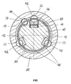
- the figure shows a longitudinal section through a rolling bearing for longitudinal movements with torque transmission capacity.
- the rolling bearing in this case comprises a rod-like inner part 10, which is surrounded by a sleeve-like outer part 20 at least in a longitudinal section.
- Each ball row comprises a plurality of balls 42.
- the balls 42 are provided for rolling in corresponding, extending in the axial direction, formed on the inner surface of the outer part 20 recesses 22.
- raceway inserts 46 are fixedly secured in their respective recesses 12, that on both sides of the rolling surface of these raceway inserts 46, the upper edges of the corresponding recess 12 are caulked.
- the raceway inserts 46 of the two lower rows of balls instead of the form-locking caulking can also be materially connected, in particular by gluing to the inner part 10.
- the raceway insert 46 is resiliently mounted in its corresponding recess 11 in the radial direction.
- a corrugated in the longitudinal direction of movement radial spring 48 is disposed between the bottom of the recess 11 and the raceway insert 46.
- the three rows of balls are further arranged in corresponding openings of a sleeve-like cage 30, which is arranged extending between the inner part 10 and the outer part 20.
- two opposing, axially extending recesses 28 and 18 are formed between the inner shell of the outer part 20 and the outer shell of the inner part, between which a needle roller 44 extending in the axial direction with its main axis is arranged.
- the needle roller 44 is arranged between the two recesses 18 and 28 with clearance and acts for the rolling bearing as a kind of overload protection, especially when the radially resiliently mounted raceway insert 46 of the upper ball row is strongly deflected.
- the stiffness is increased in said load case and secures the arrangement against overspeeding or failure by overload.
- the needle roller 44 is also arranged in the immediate vicinity of the row of balls with the spring-mounted track insert 46.
- the needle roller 44 is like the balls 42 also disposed in an opening of the cage 30 and is reciprocated with a longitudinal displacement of the two parts 10 and 20 against each other so to speak.
- the envelope forms a circular cylinder jacket.
- a bent from a thick wire coil spring is used.
Landscapes
- Engineering & Computer Science (AREA)
- General Engineering & Computer Science (AREA)
- Mechanical Engineering (AREA)
- Chemical & Material Sciences (AREA)
- Combustion & Propulsion (AREA)
- Transportation (AREA)
- Rolling Contact Bearings (AREA)
- Bearings For Parts Moving Linearly (AREA)
Abstract
- Ein Außenteil (20) mit einer das Außenteil in Längsbewegungsrichtung durchdringenden Höhlung,
- ein durch die Höhlung hindurchtretendes Innenteil (10),
- zwischen dem Innen- und dem Außenteil sind wenigstens zwei Reihen von Wälzkörpern (42) angeordnet, über die die beiden Teile gegeneinander längsbeweglich sind,
- am Innen- und/oder Außenteil sind Laufbahneinlagen (46) angeordnet, auf denen die Wälzkörper zum Abrollen vorgesehen sind,
- eine der Laufbahneinlagen einer der Wälzkörperreihen ist in einer entsprechenden Ausnehmung (11) am Innen- oder Außenteil wenigstens senkrecht zur Längsbewegungsrichtung federnd gelagert und
- eine der Laufbahnplatten der anderen Wälzkörperreihe ist in einer entsprechenden Ausnehmung (12) am Innen- oder Außenteil formschlüssig und/oder stoffschlüssig fixiert.
Description
- Die Erfindung betrifft ein Wälzlager für Längsbewegungen mit Drehmomentübertragungskapazität.
- Es ist eine Vielzahl von Wälzlagern für Längsbewegungen bekannt, bei denen zwischen zwei gegeneinander längsverschieblich gelagerten Teilen eine Mehrzahl an Wälzkörperreihen angeordnet ist. Dabei ist es ebenfalls bekannt, die Wälzkörper auf Laufbahneinlagen abrollen zu lassen, die in den entsprechenden Teilen eingelegt oder federnd gelagert sind. Weiterhin sind auch Lösungen bekannt, bei denen die federnde Lagerung wie auch die Laufbahneinlage selbst aus mehreren Teilen zusammengesetzt ausgebildet sind.
- Eine Aufgabe der vorliegenden Erfindung ist es, ein verbessertes Wälzlager für Längsbewegungen zu schaffen, das insbesondere mit einer Minderzahl an Einzelteilen auskommt und/oder bei dem die Anzahl insbesondere im noch nicht fertig montierten Zustand gegeneinander loser Einzelteile verringert ist.
- Die Aufgabe wird durch den Gegenstand des Anspruchs 1 gelöst. Vorteilhafte Ausgestaltungen sind in den Unteransprüchen beschrieben.
- Gemäß Anspruch 1 umfasst ein Wälzlager für Längsbewegungen mit Drehmomentübertragungskapazität folgende Merkmale:
- Ein Außenteil mit einer das Außenteil in Längsbewegungsrichtung durchdringenden Höhlung,
- ein durch die Höhlung hindurchtretendes Innenteil,
- zwischen dem Innen- und dem Außenteil sind wenigstens zwei Reihen von Wälzkörpern angeordnet, über die die beiden Teile gegeneinander längsbeweglich sind,
- am Innen- und/oder Außenteil sind Laufbahneinlagen angeordnet, auf denen die Wälzkörper zum Abrollen vorgesehen sind,
- eine der Laufbahneinlagen einer der Wälzkörperreihen ist in einer entsprechenden Ausnehmung am Innen- oder Außenteil wenigstens senkrecht zur Längsbewegungsrichtung federnd gelagert und
- eine der Laufbahnplatten der anderen Wälzkörperreihe ist in einer entsprechenden Ausnehmung am Innen- oder Außenteil formschlüssig und/oder stoffschlüssig fixiert.
- Dadurch, dass nur eine der Laufbahneinlagen für eine der Wälzkörperreihen radial federnd gelagert ist, wird die Anzahl an Einzelteilen gegenüber Wälzlagern, bei denen die Laufbahneinlagen aller Kugelreihen federnd gelagert sind, deutlich reduziert. Dadurch, dass die übrigen Laufbahneinlagen formschlüssig, insbesondere durch ein Verstemmen und/oder stoffschlüssig, insbesondere durch ein Verkleben, am entsprechenden Teil fixiert sind, wird durch diese verliersichere Halterung der Laufbahneinlagen beispielsweise die Montage vereinfacht und andererseits auch ein Lösen oder ein Spiel dieser Laufbahneinlagen gegenüber ihrer Aufnahme bei Betrieb des Wälzlagers mit Vorteil verhindert.
- Weiterhin wird durch das Vorhandensein lediglich einer federnd gelagerten Laufbahneinlage und besagtes Fixieren der übrigen Laufbahneinlagen mit Vorteil eine hohe Steifigkeit des Systems erzielt. Trotzdem wird durch das Vorhandensein der einer radial federnd gelagerten Laufbahneinlage wunschgemäß eine Spielfreiheit und/oder eine Vorspannung des Systems erzielt.
- In einer vorteilhaften Ausgestaltung ist zur Überlastsicherung zwischen zwei einander gegenüberliegenden, sich in Längsbewegungsrichtung erstreckenden Vertiefungen am Innenmantel des Außenteils und am Außenmantel des Innenteils wenigstens ein sich mit seiner Hauptachse in Längsbewegungsrichtung erstreckender Körper angeordnet, dessen Umhüllende ein Kreiszylindermantel ist. Dabei kann es sich bei besagtem Körper um eine Nadel- oder Zylinderrolle oder auch um eine aus einem dicken Draht gebildete Spiralfeder handeln. Besagter Körper fungiert insbesondere dann als eine Art Überlastsicherung, wenn die radial federnd gelagerte Laufbahneinlage stark ausgelenkt wird, wobei in diesem Lastfall der Körper steifigkeitserhöhend wirkt und die Anordnung gegen ein Überdrehen schützt bzw. ein Versagen durch Überlast verhindert.
- Dabei ist es weiterhin von Vorteil, wenn der Körper nahe der radial federnd gelagerten Laufbahneinlage angeordnet ist und er selbst mit einem gewissen Spiel gelagert ist. Die vorausgehend beschriebene Überlastsicherung mittels besagtem Körper ist dabei unabhängig vom Wälzlager gemäß dem Anspruch 1 generell bei allen Wälzlagern für Längsbewegungen mit Drehmomentübertragungsfähigkeit mit Vorteil einsetzbar.
- Das vorausgehend beschriebene Wälzlager ist dabei mit besonderem Vorteil bei Lenksäulen in Fahrzeugen, insbesondere Nutzfahrzeugen einsetzbar.
- Weitere Vorteile, Merkmale und Einzelheiten der Erfindung ergeben sich aus dem im folgenden beschriebenen Ausführungsbeispiel der Erfindung anhand der Figur.
- Dabei zeigt die Figur einen Längsschnitt durch ein Wälzlager für Längsbewegungen mit Drehmomentübertragungskapazität. Das Wälzlager umfasst dabei ein stangenartiges Innenteil 10, das wenigstens in einem Längsabschnitt von einem hülsenartigen Außenteil 20 umgeben ist. Über drei Reihen von als Kugeln 42 ausgebildeten Wälzkörpern sind das Innenteil 10 und das Außenteil 20 gegeneinander längsverschieblich. In Umfangsrichtung sind dabei die drei Kugelreihen gleichmäßig verteilt angeordnet. Jede Kugelreihe umfasst dabei mehrere Kugeln 42. Am Außenteil sind die Kugeln 42 zum Abrollen in entsprechenden, sich in Axialrichtung erstreckenden, am Innenmantel des Außenteils 20 ausgebildeten Ausnehmungen 22 vorgesehen.
- Am Innenteil 10 sind entsprechend den Ausnehmungen 22 am Außenteil 20 ebenfalls drei sich axial erstreckende Ausnehmungen 11 und 12 vorgesehen, in denen jeweils eine Laufbahneinlage 46 angeordnet ist, in deren rillenartiger, sich in Längsrichtung erstreckender Vertiefung die Kugeln 42 zum Abrollen vorgesehen sind. Dabei sind bei den beiden unteren Kugelreihen die Laufbahneinlagen 46 dadurch fest in ihren entsprechenden Ausnehmungen 12 befestigt, dass beiderseits der Abrollfläche dieser Laufbahneinlagen 46 die oberen Ränder der entsprechenden Ausnehmung 12 verstemmt sind. In einer anderen Ausführungsform können die Laufbahneinlagen 46 der beiden unteren Kugelreihen anstelle des einen Formschluss erzeugenden Verstemmens auch stoffschlüssig, insbesondere durch ein Verkleben mit dem Innenteil 10 verbunden sein.
- Bei der oberen Kugelreihe ist dahingegen die Laufbahneinlage 46 in ihrer entsprechenden Ausnehmung 11 in Radialrichtung federnd gelagert. Dazu ist zwischen dem Boden der Ausnehmung 11 und der Laufbahneinlage 46 eine in Längsbewegungsrichtung gewellte Radialfeder 48 angeordnet.
- Die drei Kugelreihen sind weiterhin in entsprechenden Öffnungen eines hülsenartigen Käfigs 30 angeordnet, der sich zwischen dem Innenteil 10 und dem Außenteil 20 erstreckend angeordnet ist.
- Ferner sind am Innenmantel des Außenteils 20 und am Außenmantel des Innenteils 10 zwei sich einander gegenüberliegende, in Axialrichtung erstreckende Vertiefungen 28 und 18 ausgebildet, zwischen denen eine sich mit ihrer Hauptachse in Axialrichtung erstreckende Nadelrolle 44 angeordnet ist. Die Nadelrolle 44 ist dabei zwischen den beiden Vertiefungen 18 und 28 mit Spiel angeordnet und fungiert für das Wälzlager als eine Art Überlastsicherung, insbesondere dann, wenn die radial federnd gelagerte Laufbahneinlage 46 der oberen Kugelreihe stark ausgelenkt wird. Damit wird im besagten Lastfall die Steifigkeit erhöht und sichert die Anordnung gegen ein Überdrehen bzw. Versagen durch Überlast. Dazu ist die Nadelrolle 44 auch in unmittelbarer Nähe der Kugelreihe mit der federnd gelagerten Laufbahneinlage 46 angeordnet.
- Die Nadelrolle 44 ist wie die Kugeln 42 ebenfalls in einer Öffnung des Käfigs 30 angeordnet und wird bei einem Längsverschieben der beiden Teile 10 und 20 gegeneinander sozusagen mit hin- und herbewegt. In anderen Ausführungsformen kann anstelle der Nadelrolle natürlich auch ein anderer Körper eingesetzt werden, dessen Umhüllende einen Kreiszylindermantel bildet. Insbesondere ist auch eine aus einem dicken Draht gebogene Spiralfeder einsetzbar.
Claims (22)
- Wälzlager für Längsbewegungen mit Drehmomentübertragungskapazität, umfassend folgende Merkmale:- Ein Außenteil mit einer das Außenteil in Längsbewegungsrichtung durchdringenden Höhlung,- ein durch die Höhlung hindurchtretendes Innenteil,- zwischen dem Innen- und dem Außenteil sind wenigstens zwei Reihen von Wälzkörpern angeordnet, über die die beiden Teile gegeneinander längsbeweglich sind,- am Innen- und/oder Außenteil sind Laufbahneinlagen angeordnet, auf denen die Wälzkörper zum Abrollen vorgesehen sind,- eine der Laufbahneinlagen einer der Wälzkörperreihen ist in einer entsprechenden Ausnehmung am Innen- oder Außenteil wenigstens senkrecht zur Längsbewegungsrichtung federnd gelagert und- eine der Laufbahnplatten der anderen Wälzkörperreihe ist in einer entsprechenden Ausnehmung am Innen- oder Außenteil formschlüssig und/oder stoffschlüssig fixiert.
- Wälzlager nach Anspruch 1, wobei drei in Umfangsrichtung gleichmäßig verteilt angeordnete Wälzkörperreihen vorgesehen sind, von denen lediglich eine mit einer federnd gelagerten Laufbahneinlage und die beiden anderen mit entsprechend fixierter Laufbahneinlage ausgebildet sind.
- Wälzlager nach einem der Ansprüche 1 oder 2, wobei das formschlüssige Fixieren durch ein Verstemmen des entsprechenden Teils im Bereich der Ausnehmung für die Laufbahneinlage ausgebildet ist.
- Wälzlager nach Anspruch 3, wobei beiderseits der Abrollfläche der Laufbahneinlage die oberen Begrenzungsränder der entsprechenden Ausnehmung verstemmt sind.
- Wälzlager nach einem der Ansprüche 1 bis 4, wobei das stoffschlüssige Fixieren durch ein Verkleben ausgebildet ist.
- Wälzlager nach einem der Ansprüche 1 bis 5, wobei zur federnden Lagerung zwischen einem Boden der Ausnehmung für die Laufbahnplatte und der Laufbahnplatte Federmittel angeordnet sind.
- Wälzlager nach Anspruch 6, wobei die Federmittel eine Radialfeder, insbesondere in der Ausbildung als eine in Längsbewegungsrichtung gewellte Plattfeder umfassen.
- Wälzlager nach einem der Ansprüche 1 bis 7, wobei die Wälzkörper in einem zwischen den beiden Teilen angeordneten Käfig angeordnet sind.
- Wälzlager nach einem der Ansprüche 1 bis 8, wobei zur Überlastsicherung zwischen zwei einander gegenüberliegenden, sich in Längsbewegungsrichtung erstreckenden Vertiefungen am Innenmantel des Außenteils und am Außenmantel des Innenteils wenigstens ein sich mit seiner Hauptachse in Längsbewegungsrichtung erstreckender Körper angeordnet ist, dessen Umhüllende ein Kreiszylindermantel ist.
- Wälzlager nach Anspruch 9, wobei der Körper mit im Käfig angeordnet ist.
- Wälzlager nach einem der Ansprüche 9 oder 10, wobei der Körper bezüglich der beiden Teile mit Spiel angeordnet ist.
- Wälzlager nach einem der Ansprüche 9 bis 11, wobei der Körper als eine Nadel, Zylinderrolle oder eine Spiralfeder ausgebildet ist.
- Wälzlager nach einem der Ansprüche 9 bis 12, wobei der Körper in Umfangsrichtung unmittelbar neben der Wälzkörperreihe mit der federnd gelagerten Laufbahneinlage angeordnet ist.
- Wälzlager nach einem der Ansprüche 1 bis 13, wobei die Wälzkörper innerhalb einer der Reihen in Längsbewegungsrichtung hintereinander angeordnet sind.
- Wälzlager nach einem der Ansprüche 1 bis 14, wobei die Wälzkörper als Kugeln ausgebildet sind.
- Wälzlager nach einem der Ansprüche 1 bis 15, wobei ausschließlich am Innenteil Laufbahneinlagen vorgesehen sind.
- Wälzlager nach einem der Ansprüche 1 bis 16, wobei am Außenteil die Wälzkörper unmittelbar in entsprechenden Ausnehmungen zum Abrollen vorgesehen sind.
- Wälzlager nach einem der Ansprüche 1 bis 17, wobei die Laufbahneinlagen als Abrollflächen für die Wälzkörper mit sich in Längsbewegungsrichtung erstreckenden, rillenartigen Vertiefungen ausgebildet sind.
- Wälzlager nach einem der Ansprüche 1 bis 18, wobei die Höhlung durch einen im wesentlichen zylindrischen, insbesondere kreiszylindrischen Innenmantel des Außenteils begrenzt ist.
- Wälzlager nach einem der Ansprüche 1 bis 19, wobei der Außenmantel des Innenteils wenigstens im Längsbewegungsbereich innerhalb des Außenteils im wesentlichen zylindrisch, insbesondere kreiszylindrisch ausgebildet ist.
- Wälzlager nach einem der Ansprüche 1 bis 20, wobei das Außenteil und/oder der Käfig hülsenartig ausgebildet sind.
- Wälzlager nach einem der Ansprüche 1 bis 21, wobei das Innenteil stangenartig ausgebildet ist.
Applications Claiming Priority (1)
| Application Number | Priority Date | Filing Date | Title |
|---|---|---|---|
| DE102007007445.1A DE102007007445B4 (de) | 2007-02-15 | 2007-02-15 | Wälzlager |
Publications (3)
| Publication Number | Publication Date |
|---|---|
| EP1959147A2 true EP1959147A2 (de) | 2008-08-20 |
| EP1959147A3 EP1959147A3 (de) | 2017-03-29 |
| EP1959147B1 EP1959147B1 (de) | 2020-06-17 |
Family
ID=39560964
Family Applications (1)
| Application Number | Title | Priority Date | Filing Date |
|---|---|---|---|
| EP08002542.2A Not-in-force EP1959147B1 (de) | 2007-02-15 | 2008-02-12 | Linearwälzlager |
Country Status (2)
| Country | Link |
|---|---|
| EP (1) | EP1959147B1 (de) |
| DE (1) | DE102007007445B4 (de) |
Family Cites Families (10)
| Publication number | Priority date | Publication date | Assignee | Title |
|---|---|---|---|---|
| US3900233A (en) * | 1973-01-19 | 1975-08-19 | Thomson Ind Inc | Linear motion ball bearing assembly and ball conforming shaft |
| DE3118386A1 (de) * | 1981-05-09 | 1982-11-25 | Skf Kugellagerfabriken Gmbh | Waelzlager fuer laengsbewegungen |
| DE3813422A1 (de) * | 1988-04-21 | 1989-11-02 | Lemfoerder Metallwaren Ag | Teleskopierbare lenkwelle fuer kraftfahrzeuge |
| US5201584A (en) * | 1991-09-18 | 1993-04-13 | At&T Bell Laboratories | Mechanism for preloading linear bearing slides |
| SE506402C2 (sv) * | 1996-08-30 | 1997-12-08 | Kolungen Ab | Styrningssystem mellan en slid och en gejder |
| FR2795785B1 (fr) * | 1999-06-30 | 2002-06-28 | Nacam | Dispositif d'accouplement a billes de deux arbres coulissants |
| ES2162713T3 (es) * | 1999-12-10 | 2002-01-01 | Skf Linearsysteme Gmbh | Cojinete de rodamientos para movimientos longitudinales. |
| WO2002055895A1 (en) * | 2000-10-24 | 2002-07-18 | Thomson Industries, Inc. | Linear motion bearing segment |
| CN100390000C (zh) * | 2001-10-01 | 2008-05-28 | 日本精工株式会社 | 车辆转向用伸缩轴 |
| JP4770193B2 (ja) * | 2005-02-16 | 2011-09-14 | 日本精工株式会社 | 車両ステアリング用伸縮軸 |
-
2007
- 2007-02-15 DE DE102007007445.1A patent/DE102007007445B4/de not_active Expired - Fee Related
-
2008
- 2008-02-12 EP EP08002542.2A patent/EP1959147B1/de not_active Not-in-force
Also Published As
| Publication number | Publication date |
|---|---|
| DE102007007445B4 (de) | 2014-04-03 |
| EP1959147B1 (de) | 2020-06-17 |
| EP1959147A3 (de) | 2017-03-29 |
| DE102007007445A1 (de) | 2008-08-28 |
Similar Documents
| Publication | Publication Date | Title |
|---|---|---|
| EP2212572B1 (de) | Radial-axial-wälzlager | |
| EP1864028B1 (de) | Radialwälzlager, insbesondere einreihiges rillenkugellager | |
| DE2422488C2 (de) | Wälzlager mit eingesetzten Laufbahnen | |
| EP4105506B1 (de) | Käfigsegment für einen rollenlagerkäfig | |
| DE102007004998A1 (de) | Drehlageranordnung | |
| DE102009037422A1 (de) | Käfigsegment für einen Kunststoffkäfig eines Wälzlagers und Wälzlager mit einem solchen Käfigsegment | |
| EP2265833B1 (de) | Umlaufführung für wälzkörper und damit ausgerüstete linear-führungseinheit | |
| DE102005059033A1 (de) | Radialwälzlager, insbesondere einreihiges Rillenwälzlager | |
| EP2232091B1 (de) | Käfig für wälzkörper | |
| DE102007049442B4 (de) | Rolle, insbesondere Standrolle für eine Postverteileranlage | |
| DE102006012598B4 (de) | Wälzlager | |
| DE202008001576U1 (de) | Gewindetrieb | |
| DE102005003987B4 (de) | Spielfreies Radialkugellager | |
| WO1993010366A1 (de) | Kugellager zur abstützung von linear bewegten wellen | |
| DE102010051268A1 (de) | Elektromechanische Fahrzeuglenkung mit Kugelgewindetrieb | |
| DE10101054B4 (de) | Halteteil | |
| WO2010009697A1 (de) | Antriebsanordnung für ein stufenlos verstellbares getriebe eines kraftfahrzeuges | |
| WO2006021273A1 (de) | Radiallageranordnung und radiallager, insbesondere für eine spindellagerung | |
| DE102007007445B4 (de) | Wälzlager | |
| DE102008056202A1 (de) | Gleitlager | |
| DE2522643B2 (de) | Rollenkaefige fuer losradlagerungen | |
| DE102016102863A1 (de) | Lenkzwischenwelle für ein Kraftfahrzeug und Verfahren zum Betreiben einer Lenkzwischenwelle für ein Kraftfahrzeug | |
| DE202008017091U1 (de) | Segmentkäfig | |
| DE2444340A1 (de) | Waelzlagerkaefig | |
| DE102009052179A1 (de) | Lagerungseinheit zur Aufnahme radialer und axialer Kräfte, Verfahren zum Messen des Axialspiels der Lagerringe einer Lagerungseinheit sowie Abpassscheibe |
Legal Events
| Date | Code | Title | Description |
|---|---|---|---|
| PUAI | Public reference made under article 153(3) epc to a published international application that has entered the european phase |
Free format text: ORIGINAL CODE: 0009012 |
|
| AK | Designated contracting states |
Kind code of ref document: A2 Designated state(s): AT BE BG CH CY CZ DE DK EE ES FI FR GB GR HR HU IE IS IT LI LT LU LV MC MT NL NO PL PT RO SE SI SK TR |
|
| AX | Request for extension of the european patent |
Extension state: AL BA MK RS |
|
| PUAL | Search report despatched |
Free format text: ORIGINAL CODE: 0009013 |
|
| AK | Designated contracting states |
Kind code of ref document: A3 Designated state(s): AT BE BG CH CY CZ DE DK EE ES FI FR GB GR HR HU IE IS IT LI LT LU LV MC MT NL NO PL PT RO SE SI SK TR |
|
| AX | Request for extension of the european patent |
Extension state: AL BA MK RS |
|
| RIC1 | Information provided on ipc code assigned before grant |
Ipc: F16C 29/04 20060101AFI20170221BHEP Ipc: B62D 1/185 20060101ALI20170221BHEP Ipc: F16C 3/035 20060101ALN20170221BHEP Ipc: F16C 39/02 20060101ALN20170221BHEP Ipc: F16D 3/06 20060101ALI20170221BHEP Ipc: F16C 29/12 20060101ALI20170221BHEP |
|
| STAA | Information on the status of an ep patent application or granted ep patent |
Free format text: STATUS: REQUEST FOR EXAMINATION WAS MADE |
|
| 17P | Request for examination filed |
Effective date: 20170831 |
|
| RBV | Designated contracting states (corrected) |
Designated state(s): AT BE BG CH CY CZ DE DK EE ES FI FR GB GR HR HU IE IS IT LI LT LU LV MC MT NL NO PL PT RO SE SI SK TR |
|
| RBV | Designated contracting states (corrected) |
Designated state(s): AT BE BG CH CY CZ DE DK EE ES FI FR GB GR HR HU IE IS IT LI LT LU LV MC MT NL NO PL PT RO SE SI SK TR |
|
| RBV | Designated contracting states (corrected) |
Designated state(s): AT BE BG CH CY CZ DE DK EE ES FI FR GB GR HR HU IE IS IT LI LT LU LV MC MT NL NO PL PT RO SE SI SK TR |
|
| AKX | Designation fees paid |
Designated state(s): AT BE BG CH CY CZ DE DK EE ES FI FR GB GR HR HU IE IS IT LI LT LU LV MC MT NL NO PL PT RO SE SI SK TR |
|
| AXX | Extension fees paid |
Extension state: AL Extension state: MK Extension state: RS Extension state: BA |
|
| RIC1 | Information provided on ipc code assigned before grant |
Ipc: F16C 3/035 20060101ALN20190830BHEP Ipc: F16D 3/06 20060101ALI20190830BHEP Ipc: F16C 29/04 20060101AFI20190830BHEP Ipc: B62D 1/185 20060101ALI20190830BHEP Ipc: F16C 29/12 20060101ALI20190830BHEP Ipc: F16C 39/02 20060101ALN20190830BHEP |
|
| RIC1 | Information provided on ipc code assigned before grant |
Ipc: F16C 29/12 20060101ALI20190930BHEP Ipc: F16D 3/06 20060101ALI20190930BHEP Ipc: F16C 3/035 20060101ALN20190930BHEP Ipc: F16C 39/02 20060101ALN20190930BHEP Ipc: B62D 1/185 20060101ALI20190930BHEP Ipc: F16C 29/04 20060101AFI20190930BHEP |
|
| RIC1 | Information provided on ipc code assigned before grant |
Ipc: F16C 29/04 20060101AFI20191028BHEP Ipc: F16C 3/035 20060101ALN20191028BHEP Ipc: F16D 3/06 20060101ALI20191028BHEP Ipc: F16C 29/12 20060101ALI20191028BHEP Ipc: B62D 1/185 20060101ALI20191028BHEP Ipc: F16C 39/02 20060101ALN20191028BHEP |
|
| RIC1 | Information provided on ipc code assigned before grant |
Ipc: F16C 39/02 20060101ALN20191129BHEP Ipc: F16D 3/06 20060101ALI20191129BHEP Ipc: F16C 29/04 20060101AFI20191129BHEP Ipc: F16C 29/12 20060101ALI20191129BHEP Ipc: F16C 3/035 20060101ALN20191129BHEP Ipc: B62D 1/185 20060101ALI20191129BHEP |
|
| GRAP | Despatch of communication of intention to grant a patent |
Free format text: ORIGINAL CODE: EPIDOSNIGR1 |
|
| STAA | Information on the status of an ep patent application or granted ep patent |
Free format text: STATUS: GRANT OF PATENT IS INTENDED |
|
| INTG | Intention to grant announced |
Effective date: 20200121 |
|
| GRAS | Grant fee paid |
Free format text: ORIGINAL CODE: EPIDOSNIGR3 |
|
| GRAA | (expected) grant |
Free format text: ORIGINAL CODE: 0009210 |
|
| STAA | Information on the status of an ep patent application or granted ep patent |
Free format text: STATUS: THE PATENT HAS BEEN GRANTED |
|
| AK | Designated contracting states |
Kind code of ref document: B1 Designated state(s): AT BE BG CH CY CZ DE DK EE ES FI FR GB GR HR HU IE IS IT LI LT LU LV MC MT NL NO PL PT RO SE SI SK TR |
|
| REG | Reference to a national code |
Ref country code: GB Ref legal event code: FG4D Free format text: NOT ENGLISH |
|
| REG | Reference to a national code |
Ref country code: CH Ref legal event code: EP |
|
| REG | Reference to a national code |
Ref country code: IE Ref legal event code: FG4D Free format text: LANGUAGE OF EP DOCUMENT: GERMAN |
|
| REG | Reference to a national code |
Ref country code: DE Ref legal event code: R096 Ref document number: 502008017096 Country of ref document: DE |
|
| REG | Reference to a national code |
Ref country code: AT Ref legal event code: REF Ref document number: 1281663 Country of ref document: AT Kind code of ref document: T Effective date: 20200715 |
|
| PG25 | Lapsed in a contracting state [announced via postgrant information from national office to epo] |
Ref country code: LT Free format text: LAPSE BECAUSE OF FAILURE TO SUBMIT A TRANSLATION OF THE DESCRIPTION OR TO PAY THE FEE WITHIN THE PRESCRIBED TIME-LIMIT Effective date: 20200617 Ref country code: SE Free format text: LAPSE BECAUSE OF FAILURE TO SUBMIT A TRANSLATION OF THE DESCRIPTION OR TO PAY THE FEE WITHIN THE PRESCRIBED TIME-LIMIT Effective date: 20200617 Ref country code: GR Free format text: LAPSE BECAUSE OF FAILURE TO SUBMIT A TRANSLATION OF THE DESCRIPTION OR TO PAY THE FEE WITHIN THE PRESCRIBED TIME-LIMIT Effective date: 20200918 Ref country code: NO Free format text: LAPSE BECAUSE OF FAILURE TO SUBMIT A TRANSLATION OF THE DESCRIPTION OR TO PAY THE FEE WITHIN THE PRESCRIBED TIME-LIMIT Effective date: 20200917 Ref country code: FI Free format text: LAPSE BECAUSE OF FAILURE TO SUBMIT A TRANSLATION OF THE DESCRIPTION OR TO PAY THE FEE WITHIN THE PRESCRIBED TIME-LIMIT Effective date: 20200617 |
|
| REG | Reference to a national code |
Ref country code: LT Ref legal event code: MG4D |
|
| REG | Reference to a national code |
Ref country code: NL Ref legal event code: MP Effective date: 20200617 |
|
| PG25 | Lapsed in a contracting state [announced via postgrant information from national office to epo] |
Ref country code: LV Free format text: LAPSE BECAUSE OF FAILURE TO SUBMIT A TRANSLATION OF THE DESCRIPTION OR TO PAY THE FEE WITHIN THE PRESCRIBED TIME-LIMIT Effective date: 20200617 Ref country code: HR Free format text: LAPSE BECAUSE OF FAILURE TO SUBMIT A TRANSLATION OF THE DESCRIPTION OR TO PAY THE FEE WITHIN THE PRESCRIBED TIME-LIMIT Effective date: 20200617 Ref country code: BG Free format text: LAPSE BECAUSE OF FAILURE TO SUBMIT A TRANSLATION OF THE DESCRIPTION OR TO PAY THE FEE WITHIN THE PRESCRIBED TIME-LIMIT Effective date: 20200917 |
|
| PG25 | Lapsed in a contracting state [announced via postgrant information from national office to epo] |
Ref country code: NL Free format text: LAPSE BECAUSE OF FAILURE TO SUBMIT A TRANSLATION OF THE DESCRIPTION OR TO PAY THE FEE WITHIN THE PRESCRIBED TIME-LIMIT Effective date: 20200617 |
|
| PG25 | Lapsed in a contracting state [announced via postgrant information from national office to epo] |
Ref country code: ES Free format text: LAPSE BECAUSE OF FAILURE TO SUBMIT A TRANSLATION OF THE DESCRIPTION OR TO PAY THE FEE WITHIN THE PRESCRIBED TIME-LIMIT Effective date: 20200617 Ref country code: CZ Free format text: LAPSE BECAUSE OF FAILURE TO SUBMIT A TRANSLATION OF THE DESCRIPTION OR TO PAY THE FEE WITHIN THE PRESCRIBED TIME-LIMIT Effective date: 20200617 Ref country code: IT Free format text: LAPSE BECAUSE OF FAILURE TO SUBMIT A TRANSLATION OF THE DESCRIPTION OR TO PAY THE FEE WITHIN THE PRESCRIBED TIME-LIMIT Effective date: 20200617 Ref country code: RO Free format text: LAPSE BECAUSE OF FAILURE TO SUBMIT A TRANSLATION OF THE DESCRIPTION OR TO PAY THE FEE WITHIN THE PRESCRIBED TIME-LIMIT Effective date: 20200617 Ref country code: EE Free format text: LAPSE BECAUSE OF FAILURE TO SUBMIT A TRANSLATION OF THE DESCRIPTION OR TO PAY THE FEE WITHIN THE PRESCRIBED TIME-LIMIT Effective date: 20200617 Ref country code: PT Free format text: LAPSE BECAUSE OF FAILURE TO SUBMIT A TRANSLATION OF THE DESCRIPTION OR TO PAY THE FEE WITHIN THE PRESCRIBED TIME-LIMIT Effective date: 20201019 |
|
| PG25 | Lapsed in a contracting state [announced via postgrant information from national office to epo] |
Ref country code: IS Free format text: LAPSE BECAUSE OF FAILURE TO SUBMIT A TRANSLATION OF THE DESCRIPTION OR TO PAY THE FEE WITHIN THE PRESCRIBED TIME-LIMIT Effective date: 20201017 Ref country code: SK Free format text: LAPSE BECAUSE OF FAILURE TO SUBMIT A TRANSLATION OF THE DESCRIPTION OR TO PAY THE FEE WITHIN THE PRESCRIBED TIME-LIMIT Effective date: 20200617 Ref country code: PL Free format text: LAPSE BECAUSE OF FAILURE TO SUBMIT A TRANSLATION OF THE DESCRIPTION OR TO PAY THE FEE WITHIN THE PRESCRIBED TIME-LIMIT Effective date: 20200617 |
|
| REG | Reference to a national code |
Ref country code: DE Ref legal event code: R097 Ref document number: 502008017096 Country of ref document: DE |
|
| PLBE | No opposition filed within time limit |
Free format text: ORIGINAL CODE: 0009261 |
|
| STAA | Information on the status of an ep patent application or granted ep patent |
Free format text: STATUS: NO OPPOSITION FILED WITHIN TIME LIMIT |
|
| PG25 | Lapsed in a contracting state [announced via postgrant information from national office to epo] |
Ref country code: DK Free format text: LAPSE BECAUSE OF FAILURE TO SUBMIT A TRANSLATION OF THE DESCRIPTION OR TO PAY THE FEE WITHIN THE PRESCRIBED TIME-LIMIT Effective date: 20200617 |
|
| 26N | No opposition filed |
Effective date: 20210318 |
|
| PG25 | Lapsed in a contracting state [announced via postgrant information from national office to epo] |
Ref country code: SI Free format text: LAPSE BECAUSE OF FAILURE TO SUBMIT A TRANSLATION OF THE DESCRIPTION OR TO PAY THE FEE WITHIN THE PRESCRIBED TIME-LIMIT Effective date: 20200617 |
|
| REG | Reference to a national code |
Ref country code: DE Ref legal event code: R119 Ref document number: 502008017096 Country of ref document: DE |
|
| PG25 | Lapsed in a contracting state [announced via postgrant information from national office to epo] |
Ref country code: MC Free format text: LAPSE BECAUSE OF FAILURE TO SUBMIT A TRANSLATION OF THE DESCRIPTION OR TO PAY THE FEE WITHIN THE PRESCRIBED TIME-LIMIT Effective date: 20200617 |
|
| GBPC | Gb: european patent ceased through non-payment of renewal fee |
Effective date: 20210212 |
|
| REG | Reference to a national code |
Ref country code: BE Ref legal event code: MM Effective date: 20210228 |
|
| PG25 | Lapsed in a contracting state [announced via postgrant information from national office to epo] |
Ref country code: LU Free format text: LAPSE BECAUSE OF NON-PAYMENT OF DUE FEES Effective date: 20210212 Ref country code: LI Free format text: LAPSE BECAUSE OF NON-PAYMENT OF DUE FEES Effective date: 20210228 Ref country code: CH Free format text: LAPSE BECAUSE OF NON-PAYMENT OF DUE FEES Effective date: 20210228 |
|
| PG25 | Lapsed in a contracting state [announced via postgrant information from national office to epo] |
Ref country code: DE Free format text: LAPSE BECAUSE OF NON-PAYMENT OF DUE FEES Effective date: 20210901 Ref country code: IE Free format text: LAPSE BECAUSE OF NON-PAYMENT OF DUE FEES Effective date: 20210212 Ref country code: FR Free format text: LAPSE BECAUSE OF NON-PAYMENT OF DUE FEES Effective date: 20210228 Ref country code: GB Free format text: LAPSE BECAUSE OF NON-PAYMENT OF DUE FEES Effective date: 20210212 |
|
| REG | Reference to a national code |
Ref country code: AT Ref legal event code: MM01 Ref document number: 1281663 Country of ref document: AT Kind code of ref document: T Effective date: 20210212 |
|
| PG25 | Lapsed in a contracting state [announced via postgrant information from national office to epo] |
Ref country code: AT Free format text: LAPSE BECAUSE OF NON-PAYMENT OF DUE FEES Effective date: 20210212 |
|
| PG25 | Lapsed in a contracting state [announced via postgrant information from national office to epo] |
Ref country code: BE Free format text: LAPSE BECAUSE OF NON-PAYMENT OF DUE FEES Effective date: 20210228 |
|
| PG25 | Lapsed in a contracting state [announced via postgrant information from national office to epo] |
Ref country code: HU Free format text: LAPSE BECAUSE OF FAILURE TO SUBMIT A TRANSLATION OF THE DESCRIPTION OR TO PAY THE FEE WITHIN THE PRESCRIBED TIME-LIMIT; INVALID AB INITIO Effective date: 20080212 Ref country code: CY Free format text: LAPSE BECAUSE OF FAILURE TO SUBMIT A TRANSLATION OF THE DESCRIPTION OR TO PAY THE FEE WITHIN THE PRESCRIBED TIME-LIMIT Effective date: 20200617 |
|
| PG25 | Lapsed in a contracting state [announced via postgrant information from national office to epo] |
Ref country code: TR Free format text: LAPSE BECAUSE OF FAILURE TO SUBMIT A TRANSLATION OF THE DESCRIPTION OR TO PAY THE FEE WITHIN THE PRESCRIBED TIME-LIMIT Effective date: 20200617 |
|
| PG25 | Lapsed in a contracting state [announced via postgrant information from national office to epo] |
Ref country code: MT Free format text: LAPSE BECAUSE OF FAILURE TO SUBMIT A TRANSLATION OF THE DESCRIPTION OR TO PAY THE FEE WITHIN THE PRESCRIBED TIME-LIMIT Effective date: 20200617 |