EP1959096B1 - Procédé de refroidissement d'un élément d'une turbomachine par jet - Google Patents
Procédé de refroidissement d'un élément d'une turbomachine par jet Download PDFInfo
- Publication number
- EP1959096B1 EP1959096B1 EP08151497.8A EP08151497A EP1959096B1 EP 1959096 B1 EP1959096 B1 EP 1959096B1 EP 08151497 A EP08151497 A EP 08151497A EP 1959096 B1 EP1959096 B1 EP 1959096B1
- Authority
- EP
- European Patent Office
- Prior art keywords
- cooling
- air
- impingement
- cooling air
- cool
- Prior art date
- Legal status (The legal status is an assumption and is not a legal conclusion. Google has not performed a legal analysis and makes no representation as to the accuracy of the status listed.)
- Ceased
Links
- 238000001816 cooling Methods 0.000 title claims description 71
- 238000000034 method Methods 0.000 title claims description 10
- 230000000694 effects Effects 0.000 claims description 12
- 238000005192 partition Methods 0.000 claims description 9
- 230000000737 periodic effect Effects 0.000 claims description 4
- 230000015572 biosynthetic process Effects 0.000 claims description 2
- 230000005284 excitation Effects 0.000 claims 2
- 230000000149 penetrating effect Effects 0.000 claims 1
- 239000007789 gas Substances 0.000 description 11
- 230000010349 pulsation Effects 0.000 description 2
- 230000004075 alteration Effects 0.000 description 1
- 230000001427 coherent effect Effects 0.000 description 1
- 239000000567 combustion gas Substances 0.000 description 1
- 238000002485 combustion reaction Methods 0.000 description 1
- 230000001419 dependent effect Effects 0.000 description 1
- 238000011161 development Methods 0.000 description 1
- 230000018109 developmental process Effects 0.000 description 1
- 230000010355 oscillation Effects 0.000 description 1
Images
Classifications
-
- F—MECHANICAL ENGINEERING; LIGHTING; HEATING; WEAPONS; BLASTING
- F01—MACHINES OR ENGINES IN GENERAL; ENGINE PLANTS IN GENERAL; STEAM ENGINES
- F01D—NON-POSITIVE DISPLACEMENT MACHINES OR ENGINES, e.g. STEAM TURBINES
- F01D25/00—Component parts, details, or accessories, not provided for in, or of interest apart from, other groups
- F01D25/08—Cooling; Heating; Heat-insulation
- F01D25/12—Cooling
-
- F—MECHANICAL ENGINEERING; LIGHTING; HEATING; WEAPONS; BLASTING
- F01—MACHINES OR ENGINES IN GENERAL; ENGINE PLANTS IN GENERAL; STEAM ENGINES
- F01D—NON-POSITIVE DISPLACEMENT MACHINES OR ENGINES, e.g. STEAM TURBINES
- F01D5/00—Blades; Blade-carrying members; Heating, heat-insulating, cooling or antivibration means on the blades or the members
- F01D5/12—Blades
- F01D5/14—Form or construction
- F01D5/18—Hollow blades, i.e. blades with cooling or heating channels or cavities; Heating, heat-insulating or cooling means on blades
- F01D5/187—Convection cooling
-
- F—MECHANICAL ENGINEERING; LIGHTING; HEATING; WEAPONS; BLASTING
- F05—INDEXING SCHEMES RELATING TO ENGINES OR PUMPS IN VARIOUS SUBCLASSES OF CLASSES F01-F04
- F05D—INDEXING SCHEME FOR ASPECTS RELATING TO NON-POSITIVE-DISPLACEMENT MACHINES OR ENGINES, GAS-TURBINES OR JET-PROPULSION PLANTS
- F05D2260/00—Function
- F05D2260/20—Heat transfer, e.g. cooling
- F05D2260/201—Heat transfer, e.g. cooling by impingement of a fluid
-
- F—MECHANICAL ENGINEERING; LIGHTING; HEATING; WEAPONS; BLASTING
- F23—COMBUSTION APPARATUS; COMBUSTION PROCESSES
- F23R—GENERATING COMBUSTION PRODUCTS OF HIGH PRESSURE OR HIGH VELOCITY, e.g. GAS-TURBINE COMBUSTION CHAMBERS
- F23R2900/00—Special features of, or arrangements for continuous combustion chambers; Combustion processes therefor
- F23R2900/03044—Impingement cooled combustion chamber walls or subassemblies
Definitions
- the invention relates to a method for impingement air cooling for gas turbines, in which cooling air impinges on formed in a partition impingement air openings in separate cooling air jets on the wall to be cooled wall area.
- impingement air cooling In gas turbine engines and stationary gas turbines, it is known to cool the highly heated components in the turbine such as rotor blades, vanes, liners or combustion chamber walls with a portion of the compressor air by means of impingement air.
- impingement air cooling the cooling air, as a steady stream of air, reaches the surface to be cooled via relatively small impingement cooling bores. Due to the strong pressure drop in the impingement cooling bores in each case a powerful air jet is formed, which causes a high heat transfer in each case in a localized area of the wall surface to be cooled.
- the EP 0 892 151 A1 For example, a channel formed in the leading edge of a turbine blade is exposed to impingement air via cooling holes from a main channel supplied with cooling air and is passed longitudinally through the blade height. An optimal cooling effect of the impact air jets is not achieved in this way.
- the disclosed EP 0 698 724 B1 a special blade formation for impingement air cooling of the trailing edge of a turbine blade with which the cooling effect of the impingement air reduced by crossflows in the impingement cooling air streams is to be improved.
- the EP 0 889 201 A1 suggests a specific shape of the wall surface to be cooled in order to increase the cooling effect of the impingement air jets.
- the invention has for its object to provide a method for the impact air cooling acted upon by hot combustion gases components of a gas turbine, with which the cooling effect of the impact air can be improved. According to the invention the object is achieved by a method according to the features of patent claim 1. From the dependent claims, further features and advantageous developments of the invention.
- the basic idea of the invention is that ring vortex structures are produced in the space between the impingement air openings and the wall of the engine component to be cooled instead of a continuous impingement air stream at a distance by the impingement air openings on the input side with in a certain frequency and with certain amplitude with cooling air pulses be charged.
- At a certain amplitude of the cooling air pulses and a matched size of the impingement air openings are strong Ringwirbelstruk-tures
- the temperature gradients on the component wall become due to the dynamic response behavior of the temperature boundary layer on average over time higher and thereby the heat transfer is increased on the wall of the component to be cooled.
- Ring vortex structures for maximum cooling effect highest intensity are achieved by a correspondingly larger amplitude, preferably at a certain resonant frequency
- the distance between the partition wall and the wall region to be cooled is chosen according to the invention such that resonance conditions prevail between the ring vortices generated at the impact air openings and the pressure waves induced and reflected due to the occurring ring vortices and thus an intensification of the ring vortex structures can be observed.
- the periodic generation of the ring vortex structures is interrupted at regular intervals, by the regularly recurring pauses in the periodic ring vorticity of the cooling air mass flow can be reduced with the same cooling effect.
- the improved cooling effect due to the ring vortex structures of the impingement air generated in a certain frequency reduces the cooling air requirement and increases the efficiency of the turbine or the life of the highly heated turbine components.
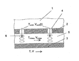
- a cavity 1 of an engine component for example, a blade of a turbine stage
- a temperature T cool a time-varying, ie in the speed periodically - for example, sinusoidal - changing cooling air mass flow, consisting of at a time interval consecutive cooling air velocity sacred V cool (t) with a certain amplitude V cool , introduced.
- a hot gas with a temperature T and a velocity V flows along the outer wall 3 of the engine component to be cooled.
- a partition wall 2 with impact air openings 4 is arranged at a distance from the outer wall 3, which with the temporally successive speed packets V cool (t ) of the unsteady cooling air mass flow are applied.
- the cooling air reaches the inner surface of the outer wall 3 and flows in a transverse flow at the speed V cross in the cooling air channel formed between the outer wall 3 and the partition 2 5 via openings, not shown, for example, film cooling holes, to the outside. Due to the periodic loading of the impingement air openings 4 with the cooling air velocity packets V cool (t), periodically successive strong ring vortex structures 6 are formed at their exit when they impinge on the transverse flow.
- the annular vortex structures 6 of the cooling air are able to substantially completely penetrate the cooling air channel 5 present between the dividing wall and the outer wall or the transverse flow present in the outer wall and thus strike the inner surface of the outer wall 3 with high intensity, which is better than with is cooled according to the prior art provided a steady impingement air flow.
- the new cooling method can be used on stationary gas turbines and gas turbine engines for impingement air cooling of rotor blades, vanes, liners and platforms as well as turbine and combustor housings.
Landscapes
- Engineering & Computer Science (AREA)
- Mechanical Engineering (AREA)
- General Engineering & Computer Science (AREA)
- Turbine Rotor Nozzle Sealing (AREA)
Claims (5)
- Procédé de refroidissement d'air d'impact pour turbines à gaz, dans lequel de l'air de refroidissement percute en jets d'air de refroidissement séparés la zone de paroi à refroidir en passant par des orifices d'air d'impact formés dans une cloison et est de nouveau évacué dans un flux transversal, dans lequel que dans le flux transversal sont générées à intervalles de temps successifs des structures de tourbillonnement annulaire (6) à fort effet réfrigérant qui, avec une intensité et une fréquence élevées, traversent le flux transversal et percutent la zone de paroi à refroidir, par le fait que les orifices d'air d'impact (4) sont alimentés côté entrée avec des paquets de vélocité d'air de refroidissement (Vcool(t)) d'une amplitude (Vcool) et d'une fréquence (f) définies, dans lequel le rapport entre la fréquence (f) et l'amplitude (Vcool) des paquets de vélocité d'air de refroidissement et la taille (D) des orifices d'air d'impact (4) est déterminé par le nombre de Strouhal (Sr = f x D/Vcool), et qu'afin d'exciter les structures de tourbillonnement annulaire, le nombre de Strouhal (Sr) se situe dans la plage comprise entre 0,2 et 2,0.
- Procédé selon la revendication 1, caractérisé en ce que la formation et l'intensité des structures de tourbillonnement annulaire (6) sont déterminées par l'amplitude des paquets de vélocité d'air de refroidissement et la taille (D) des orifices d'air d'impact (4).
- Procédé selon la revendication 1, caractérisé en ce que le nombre d'excitation de Strouhal se situe dans la plage comprise entre 0,8 et 1,2.
- Procédé selon la revendication 1, caractérisé en ce que pour intensifier les structures de tourbillonnement annulaire, la distance entre la cloison et la zone de paroi à refroidir est définie de manière telle que dans l'espace entre la cloison et la paroi à refroidir règnent des conditions de résonance entre les tourbillons annulaires sur les orifices d'air d'impact et les ondes de pression réfléchies.
- Procédé selon la revendication 1, caractérisé en ce que la création périodique des structures de tourbillonnement annulaire (6) est interrompue à intervalles de temps réguliers afin d'économiser de l'air de refroidissement.
Applications Claiming Priority (1)
| Application Number | Priority Date | Filing Date | Title |
|---|---|---|---|
| DE102007008319A DE102007008319A1 (de) | 2007-02-16 | 2007-02-16 | Verfahren zur Prallluftkühlung für Gasturbinen |
Publications (3)
| Publication Number | Publication Date |
|---|---|
| EP1959096A2 EP1959096A2 (fr) | 2008-08-20 |
| EP1959096A3 EP1959096A3 (fr) | 2013-02-20 |
| EP1959096B1 true EP1959096B1 (fr) | 2014-10-01 |
Family
ID=39144432
Family Applications (1)
| Application Number | Title | Priority Date | Filing Date |
|---|---|---|---|
| EP08151497.8A Ceased EP1959096B1 (fr) | 2007-02-16 | 2008-02-15 | Procédé de refroidissement d'un élément d'une turbomachine par jet |
Country Status (3)
| Country | Link |
|---|---|
| US (1) | US8152463B2 (fr) |
| EP (1) | EP1959096B1 (fr) |
| DE (1) | DE102007008319A1 (fr) |
Families Citing this family (8)
| Publication number | Priority date | Publication date | Assignee | Title |
|---|---|---|---|---|
| US9458855B2 (en) | 2010-12-30 | 2016-10-04 | Rolls-Royce North American Technologies Inc. | Compressor tip clearance control and gas turbine engine |
| DE102011078138A1 (de) | 2011-06-27 | 2012-12-27 | Rolls-Royce Deutschland Ltd & Co Kg | Vorrichtung und Verfahren zur Erzeugung eines Ringwirbel ausbildenden Prallstrahls sowie Turbomaschine mit einer derartigen Vorrichtung |
| US9482249B2 (en) * | 2013-09-09 | 2016-11-01 | General Electric Company | Three-dimensional printing process, swirling device and thermal management process |
| DE102013112725A1 (de) | 2013-11-19 | 2015-05-21 | Hochschule Karlsruhe | Prallstrahlkühlvorrichtung |
| US10208603B2 (en) | 2014-11-18 | 2019-02-19 | United Technologies Corporation | Staggered crossovers for airfoils |
| CN105927288A (zh) * | 2016-06-02 | 2016-09-07 | 西北工业大学 | 一种转子件凸台式周期性压力波产生装置 |
| US10480327B2 (en) | 2017-01-03 | 2019-11-19 | General Electric Company | Components having channels for impingement cooling |
| CN113153444B (zh) * | 2021-04-09 | 2022-12-09 | 西安交通大学 | 一种基于超声波强化传热的透平叶片内部冲击冷却结构 |
Family Cites Families (16)
| Publication number | Priority date | Publication date | Assignee | Title |
|---|---|---|---|---|
| DE2010607A1 (de) * | 1969-03-08 | 1970-09-24 | Rolls-Royce Ltd., Derby (Großbritannien) | Flugzeugstrahltriebwerk |
| US4095417A (en) * | 1976-08-23 | 1978-06-20 | Avco Corporation | Apparatus for and method of suppressing infrared radiation emitted from gas turbine engine |
| IN170251B (fr) * | 1987-04-16 | 1992-03-07 | Luminis Pty Ltd | |
| JP3415663B2 (ja) | 1992-12-28 | 2003-06-09 | アルストム | 冷却面を衝撃式に冷却するための装置 |
| DE4244302C2 (de) * | 1992-12-28 | 2002-08-29 | Alstom | Vorrichtung zur Prallkühlung |
| US5391052A (en) * | 1993-11-16 | 1995-02-21 | General Electric Co. | Impingement cooling and cooling medium retrieval system for turbine shrouds and methods of operation |
| US5464322A (en) | 1994-08-23 | 1995-11-07 | General Electric Company | Cooling circuit for turbine stator vane trailing edge |
| DE4430302A1 (de) * | 1994-08-26 | 1996-02-29 | Abb Management Ag | Prallgekühltes Wandteil |
| DE19520291A1 (de) * | 1995-06-02 | 1996-12-05 | Abb Management Ag | Brennkammer |
| GB2326706A (en) * | 1997-06-25 | 1998-12-30 | Europ Gas Turbines Ltd | Heat transfer structure |
| DE59709153D1 (de) | 1997-07-03 | 2003-02-20 | Alstom Switzerland Ltd | Prallanordnung für ein konvektives Kühl-oder Heizverfahren |
| EP0892151A1 (fr) | 1997-07-15 | 1999-01-20 | Asea Brown Boveri AG | Système de refroidissement pour le bord d'attaque d'une aube de turbine à gas |
| US6053203A (en) * | 1997-08-15 | 2000-04-25 | Administrators Of The Tulane Educational Fund | Mechanically-driven pulsating flow valve for heat and mass transfer enhancement |
| DE29714742U1 (de) * | 1997-08-18 | 1998-12-17 | Siemens AG, 80333 München | Hitzeschildkomponente mit Kühlfluidrückführung und Hitzeschildanordnung für eine heißgasführende Komponente |
| WO1999067539A1 (fr) * | 1998-06-01 | 1999-12-29 | The Penn State Research Foundation | L'ailette oscillante, nouveau dispositif d'accroissement des transferts thermiques |
| DE10202783A1 (de) * | 2002-01-25 | 2003-07-31 | Alstom Switzerland Ltd | Gekühltes Bauteil für eine thermische Maschine, insbesondere eine Gasturbine |
-
2007
- 2007-02-16 DE DE102007008319A patent/DE102007008319A1/de not_active Withdrawn
-
2008
- 2008-02-15 EP EP08151497.8A patent/EP1959096B1/fr not_active Ceased
- 2008-02-15 US US12/071,156 patent/US8152463B2/en active Active
Also Published As
| Publication number | Publication date |
|---|---|
| EP1959096A3 (fr) | 2013-02-20 |
| DE102007008319A1 (de) | 2008-08-21 |
| EP1959096A2 (fr) | 2008-08-20 |
| US8152463B2 (en) | 2012-04-10 |
| US20080226441A1 (en) | 2008-09-18 |
Similar Documents
| Publication | Publication Date | Title |
|---|---|---|
| EP1959096B1 (fr) | Procédé de refroidissement d'un élément d'une turbomachine par jet | |
| DE102007007177B4 (de) | Verfahren und Vorrichtung zum Kühlen von Gasturbinen- Rotorschaufeln | |
| DE60224339T2 (de) | Kühleinsatz mit tangentialer Ausströmung | |
| DE60031077T2 (de) | Turbinenschaufel mit unterschiedlich geneigten Filmkühlungsöffnungen | |
| DE3200972C2 (fr) | ||
| DE60027390T2 (de) | Gekühlte Gasturbinenschaufel und deren Herstellungsmethode | |
| DE102010037811B4 (de) | Vorrichtung und Verfahren zum Kühlen von Düsen | |
| EP0899425B1 (fr) | Aube pour une turbine à gaz | |
| DE69500735T2 (de) | Gasturbinenschaufel | |
| EP0203431B1 (fr) | Canal de transition refroidi par impact | |
| EP2300686B1 (fr) | Turbine à gaz pourvue d'une aube directrice | |
| CH703144B1 (de) | Turbinenschaufel, Turbinenrotor, und Verfahren zur Kühlung einer Turbinenschaufel. | |
| DE60021658T2 (de) | Hinterkantenkühlung einer Turbinenschaufel | |
| DE102010016442A1 (de) | Flanschgekühlte Turbinendüse | |
| DE102008055522A1 (de) | Divergente Turbinendüse | |
| CH703549A2 (de) | Brennkammerflammrohr mit Kühlsystem. | |
| EP0576717A1 (fr) | Chambre de combustion de turbine à gaz | |
| WO2016037966A1 (fr) | Brûleur comprenant un oscillateur fluidique pour une turbine à gaz et turbine à gaz comprenant au moins un brûleur de ce type | |
| EP0489193A1 (fr) | Chambre de combustion pour turbine à gaz | |
| EP0718483A2 (fr) | Turbine à gaz avec injection de vapeur | |
| CH701304B1 (de) | Turbinenschaufel mit sich verengendem und sich vergrösserndem Kühlloch. | |
| DE102012100660A1 (de) | Turbinenschaufel zur Verwendung in Gasturbinen und Verfahren zur Herstellung derselben | |
| EP1219780B1 (fr) | Dispositif et procédé de refroidissement d'un élément d'une turbomachine par jet | |
| EP2584148A1 (fr) | Aube de turbine refroidie par film pour une turbomachine | |
| WO2003054356A1 (fr) | Piece a sollicitation thermique |
Legal Events
| Date | Code | Title | Description |
|---|---|---|---|
| PUAI | Public reference made under article 153(3) epc to a published international application that has entered the european phase |
Free format text: ORIGINAL CODE: 0009012 |
|
| AK | Designated contracting states |
Kind code of ref document: A2 Designated state(s): AT BE BG CH CY CZ DE DK EE ES FI FR GB GR HR HU IE IS IT LI LT LU LV MC MT NL NO PL PT RO SE SI SK TR |
|
| AX | Request for extension of the european patent |
Extension state: AL BA MK RS |
|
| PUAL | Search report despatched |
Free format text: ORIGINAL CODE: 0009013 |
|
| AK | Designated contracting states |
Kind code of ref document: A3 Designated state(s): AT BE BG CH CY CZ DE DK EE ES FI FR GB GR HR HU IE IS IT LI LT LU LV MC MT NL NO PL PT RO SE SI SK TR |
|
| AX | Request for extension of the european patent |
Extension state: AL BA MK RS |
|
| RIC1 | Information provided on ipc code assigned before grant |
Ipc: F01D 25/12 20060101ALI20130116BHEP Ipc: F01D 5/18 20060101AFI20130116BHEP |
|
| 17P | Request for examination filed |
Effective date: 20130820 |
|
| RBV | Designated contracting states (corrected) |
Designated state(s): AT BE BG CH CY CZ DE DK EE ES FI FR GB GR HR HU IE IS IT LI LT LU LV MC MT NL NO PL PT RO SE SI SK TR |
|
| AKX | Designation fees paid |
Designated state(s): DE FR GB |
|
| GRAP | Despatch of communication of intention to grant a patent |
Free format text: ORIGINAL CODE: EPIDOSNIGR1 |
|
| INTG | Intention to grant announced |
Effective date: 20140509 |
|
| GRAS | Grant fee paid |
Free format text: ORIGINAL CODE: EPIDOSNIGR3 |
|
| RIN1 | Information on inventor provided before grant (corrected) |
Inventor name: JENS, TAEGE Inventor name: DR. ERIK, JANKE Inventor name: DR. FRANK, HASELBACH Inventor name: DR. MATTHIAS, REYER Inventor name: DR. TIMM, JANETZKE Inventor name: PROF. DR. WOFLGANG NITSCHE |
|
| GRAA | (expected) grant |
Free format text: ORIGINAL CODE: 0009210 |
|
| AK | Designated contracting states |
Kind code of ref document: B1 Designated state(s): DE FR GB |
|
| REG | Reference to a national code |
Ref country code: GB Ref legal event code: FG4D Free format text: NOT ENGLISH |
|
| REG | Reference to a national code |
Ref country code: DE Ref legal event code: R096 Ref document number: 502008012267 Country of ref document: DE Effective date: 20141113 |
|
| REG | Reference to a national code |
Ref country code: DE Ref legal event code: R097 Ref document number: 502008012267 Country of ref document: DE |
|
| PLBE | No opposition filed within time limit |
Free format text: ORIGINAL CODE: 0009261 |
|
| STAA | Information on the status of an ep patent application or granted ep patent |
Free format text: STATUS: NO OPPOSITION FILED WITHIN TIME LIMIT |
|
| 26N | No opposition filed |
Effective date: 20150702 |
|
| REG | Reference to a national code |
Ref country code: FR Ref legal event code: PLFP Year of fee payment: 9 |
|
| REG | Reference to a national code |
Ref country code: FR Ref legal event code: PLFP Year of fee payment: 10 |
|
| REG | Reference to a national code |
Ref country code: FR Ref legal event code: PLFP Year of fee payment: 11 |
|
| PGFP | Annual fee paid to national office [announced via postgrant information from national office to epo] |
Ref country code: DE Payment date: 20200227 Year of fee payment: 13 Ref country code: GB Payment date: 20200227 Year of fee payment: 13 |
|
| PGFP | Annual fee paid to national office [announced via postgrant information from national office to epo] |
Ref country code: FR Payment date: 20200225 Year of fee payment: 13 |
|
| REG | Reference to a national code |
Ref country code: DE Ref legal event code: R119 Ref document number: 502008012267 Country of ref document: DE |
|
| GBPC | Gb: european patent ceased through non-payment of renewal fee |
Effective date: 20210215 |
|
| PG25 | Lapsed in a contracting state [announced via postgrant information from national office to epo] |
Ref country code: DE Free format text: LAPSE BECAUSE OF NON-PAYMENT OF DUE FEES Effective date: 20210901 Ref country code: GB Free format text: LAPSE BECAUSE OF NON-PAYMENT OF DUE FEES Effective date: 20210215 Ref country code: FR Free format text: LAPSE BECAUSE OF NON-PAYMENT OF DUE FEES Effective date: 20210228 |