EP1959068B1 - Device for renovating flat roofs - Google Patents
Device for renovating flat roofs Download PDFInfo
- Publication number
- EP1959068B1 EP1959068B1 EP07003415A EP07003415A EP1959068B1 EP 1959068 B1 EP1959068 B1 EP 1959068B1 EP 07003415 A EP07003415 A EP 07003415A EP 07003415 A EP07003415 A EP 07003415A EP 1959068 B1 EP1959068 B1 EP 1959068B1
- Authority
- EP
- European Patent Office
- Prior art keywords
- roof
- flat roof
- renovation
- flat
- attachment
- Prior art date
- Legal status (The legal status is an assumption and is not a legal conclusion. Google has not performed a legal analysis and makes no representation as to the accuracy of the status listed.)
- Active
Links
- 239000000463 material Substances 0.000 claims abstract description 17
- 238000009418 renovation Methods 0.000 claims abstract description 14
- 239000004753 textile Substances 0.000 claims abstract description 4
- 238000004873 anchoring Methods 0.000 claims description 2
- 238000003466 welding Methods 0.000 claims description 2
- 238000010276 construction Methods 0.000 description 7
- 238000009413 insulation Methods 0.000 description 3
- 229910000831 Steel Inorganic materials 0.000 description 2
- 238000000034 method Methods 0.000 description 2
- 239000002985 plastic film Substances 0.000 description 2
- 239000011150 reinforced concrete Substances 0.000 description 2
- 239000010959 steel Substances 0.000 description 2
- 239000004793 Polystyrene Substances 0.000 description 1
- 229920005830 Polyurethane Foam Polymers 0.000 description 1
- 239000010426 asphalt Substances 0.000 description 1
- 239000004566 building material Substances 0.000 description 1
- 239000011248 coating agent Substances 0.000 description 1
- 238000000576 coating method Methods 0.000 description 1
- 230000001419 dependent effect Effects 0.000 description 1
- 238000001035 drying Methods 0.000 description 1
- 230000000694 effects Effects 0.000 description 1
- 238000004519 manufacturing process Methods 0.000 description 1
- 229910052751 metal Inorganic materials 0.000 description 1
- 238000012986 modification Methods 0.000 description 1
- 230000004048 modification Effects 0.000 description 1
- 229920002223 polystyrene Polymers 0.000 description 1
- 239000011496 polyurethane foam Substances 0.000 description 1
- 238000004382 potting Methods 0.000 description 1
- 238000007789 sealing Methods 0.000 description 1
- 230000006641 stabilisation Effects 0.000 description 1
- 238000011105 stabilization Methods 0.000 description 1
- 239000006228 supernatant Substances 0.000 description 1
- 239000012720 thermal barrier coating Substances 0.000 description 1
Images


Classifications
-
- E—FIXED CONSTRUCTIONS
- E04—BUILDING
- E04B—GENERAL BUILDING CONSTRUCTIONS; WALLS, e.g. PARTITIONS; ROOFS; FLOORS; CEILINGS; INSULATION OR OTHER PROTECTION OF BUILDINGS
- E04B7/00—Roofs; Roof construction with regard to insulation
- E04B7/02—Roofs; Roof construction with regard to insulation with plane sloping surfaces, e.g. saddle roofs
-
- E—FIXED CONSTRUCTIONS
- E04—BUILDING
- E04B—GENERAL BUILDING CONSTRUCTIONS; WALLS, e.g. PARTITIONS; ROOFS; FLOORS; CEILINGS; INSULATION OR OTHER PROTECTION OF BUILDINGS
- E04B7/00—Roofs; Roof construction with regard to insulation
- E04B7/14—Suspended roofs
-
- E—FIXED CONSTRUCTIONS
- E04—BUILDING
- E04D—ROOF COVERINGS; SKY-LIGHTS; GUTTERS; ROOF-WORKING TOOLS
- E04D11/00—Roof covering, as far as not restricted to features covered by only one of groups E04D1/00 - E04D9/00; Roof covering in ways not provided for by groups E04D1/00 - E04D9/00, e.g. built-up roofs, elevated load-supporting roof coverings
-
- E—FIXED CONSTRUCTIONS
- E04—BUILDING
- E04G—SCAFFOLDING; FORMS; SHUTTERING; BUILDING IMPLEMENTS OR AIDS, OR THEIR USE; HANDLING BUILDING MATERIALS ON THE SITE; REPAIRING, BREAKING-UP OR OTHER WORK ON EXISTING BUILDINGS
- E04G23/00—Working measures on existing buildings
- E04G23/02—Repairing, e.g. filling cracks; Restoring; Altering; Enlarging
- E04G23/0281—Repairing or restoring roofing or roof covering
Definitions
- the present invention relates to a device for the renovation of a flat roof of at least partially preserving the old roof structure according to the preamble of claim 1.
- the document DE 196 10 450 A1 proposes a method for the rehabilitation of a flat roof of a prefabricated reinforced concrete garage, in which purlins are placed on the flat roof, the
- GB 2228024 A From the GB 2228024 A is a roof construction with a patch on an existing flat roof second roof known.
- the patched second roof is attached to the construction of the flat roof on the carrier, with the components of the new roof structure are supported on the purlins of the old flat roof.
- the roof panels are formed from conventional sheet metal elements.
- GB 2228024 A discloses a device for refurbishing a flat roof of a building according to the preamble of claim 1.
- the invention is therefore based on the object to provide a simple way flat roofs requiring rehabilitation with a second roof, which is easy to install and is inexpensive to produce.
- the tensionable sheet material can be made in one or more parts and, for example, consist of two or more individual tensionable surface materials and be composed, for example, of two or more individual tensionable surface elements.
- the tensionable sheet material it is possible to simple Provide mounting rails between the individual webs.
- the waterproof attachment is very easy to implement due to the flexibility of the material and by simply inserting sealing elements in the mounting rails and makes handling particularly easy.
- the flexible stretchable sheet material may be, for example, a textile or a plastic sheet.
- the device for rehabilitation of a flat roof on a support device in particular in the form of a girder bridge or in the form of a lattice pipe bow to secure and support the roof structures of the old roof structure of the flat roof on holding elements and so z.
- B. bring about a drying effect of the old roof structure and thus stabilize the roof construction.
- further stabilization elements to the beams of the old roof structure via the retaining elements and to underlay the latter for example with a stable material such as a further wooden beam or a beam or the like made of reinforced concrete or steel posts.
- a particularly space-saving embodiment of the present invention provides that the fastening device can be fixed for receiving loads, in particular via fastening struts on the building, in particular on the facade and / or the eaves of the building. In this case, no additional space for mounting and fixing the second roof in the horizontal direction is needed, since only takes place a structure in the vertical direction.
- the attachment devices are height adjustable and / or rotatable. This makes a special flexible use possible. Also, on the one hand height differences of the existing flat roof can be compensated, on the other hand it is possible to set a slope or defined by simply adjusting the respective fastening devices in the second roof.
- the Berest Trentsvomchtonne for receiving loads are embedded in the foundation of the building or fixed to an area of the building, which has sufficient stability such.
- the load that is caused by the second roof can be easily derived in the foundation of the building, so that further stress on the possibly already attacked roof truss of the flat roof is avoided.
- the fastening devices can also be formed freestanding by almost completely carried by further support elements of the force application point for the load of the second roof of the fastening device and introduced into the ground in the vicinity of the flat roof construction.
- the holding elements can be formed by anchoring and / or by cable loops and / or by clamping and / or by any other conceivable possible known in the art fastening devices and in particular height-adjustable via screw connectors.
- the support device itself can be fastened by means of screwing and / or welding either to the edge region of the building to be renovated or to the fastening devices and / or its supporting pillars.
- the FIG. 1 shows a device 1 for the renovation of a flat roof 2 of a building 3.
- the device 1 is placed on the building 3 while preserving the old roof structure 4 and has four fastening devices 5 and a tensionable sheet material, which is stretched over the old roof structure 4 and so on forms over the to be rehabilitated flat roof 2 spanned second roof 6.
- the sheet material is formed here from a textile which is arranged over the four fastening devices on the flat roof 2 so that it completely covers the base of the flat roof 2.
- the flexible tensionable sheet material 6 is formed from a plastic sheet.
- the fastening devices 5 and 7 are rotatable in this embodiment, so that the assembly at the site in a position is possible, which does not correspond to the end position for clamping the second roof, but can be brought by simply turning the fasteners 5 in this.
- a device 1 according to the invention is shown, the fastening devices 5 are fixed to receive loads on the building 3 here in particular on the facade of the building 3.
- An equivalent solution is provided when the fastening devices 5 are fixed in or on the eaves of the building 3.
- fastening devices 5 for receiving loads on mounting struts 8, for example, in the foundation 9 of the building 3 or less ailing outbuildings 10.
- Such a way of forming the fastening devices 5 is in the left part of FIG. 1
- the outbuilding 10 may be an existing building, but it may also be specially rebuilt to support the mounting struts 8 and / or fixtures 5 become.
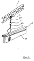
- a support device in the form of a as in FIG. 2 shown frame bridge 11 or a lattice pipe bow 12 according to the FIG. 3 intended. From the scaffold bridge 11 and the grid ear bow 12 holding elements 13a-13e are suspended, secure and support the roof structure 4 in particular its beam construction with known in the prior art mounting types, possible embodiments of the attachment are realized by anchor and by cable loops and terminals For fixing the beams of the old roof structure 4 to the framework bridge 11, the retaining element 13a-13e according to the FIG.
- the Grewindestab 14 a is welded at its free end via a sleeve 16 with the frame bridge 11.
- a screw is conceivable.
- the threaded rod 14 b is provided at its opposite free end with a scissor clip, which surrounds the wooden beams 17 of the roof structure 4, which is further provided in this embodiment with an insulating layer 18.
- the framework bridge 11, 12 can either be attached to the building 3, for example in the region of the outer walls or else to the fastening devices 5, 7 or attachment struts 8, in particular screwed or welded.
Landscapes
- Engineering & Computer Science (AREA)
- Architecture (AREA)
- Civil Engineering (AREA)
- Structural Engineering (AREA)
- Chemical & Material Sciences (AREA)
- Chemical Kinetics & Catalysis (AREA)
- Electrochemistry (AREA)
- Mechanical Engineering (AREA)
- Physics & Mathematics (AREA)
- Electromagnetism (AREA)
- Roof Covering Using Slabs Or Stiff Sheets (AREA)
- Working Measures On Existing Buildindgs (AREA)
- Tents Or Canopies (AREA)
Abstract
Description
Die vorliegende Erfindung betrifft eine Vorrichtung zur Sanierung eines Flachdaches eines unter zumindest teilweise Erhaltung des alten Dachaufbaus nach dem Oberbegriff von Anspruch 1.The present invention relates to a device for the renovation of a flat roof of at least partially preserving the old roof structure according to the preamble of claim 1.
Derartiges Vorrichtungen sind allgemein bekannt und insbesondere in der Druckschrift
Das Dokument
Pfettenfüsse aufweisen, mit denen die Pfetten an in das sanierungsbedürftige Flachdach befestigt werden. Auf die Pfetten wird ein Stahlblech-Zweitdach aufgesetzt, welches das Flachdach mit einem Überstand abgedeckt. Der Transport dieser Zweitdächer z. B. auf Baustellen ist aufgrund der recht großen Abmaße bei größeren Gebäuden sehr aufwendig und teuer und somit nicht zweckmäßig. Auch die Montage so großer Einzelbauteile ist aufgrund der Sperrigkeit und ihres Gewichts sehr schwierig.Have purlin feet, with which the purlins are attached to the flat roof requiring rehabilitation. On the purlins, a second sheet steel roof is placed, which covered the flat roof with a supernatant. The transport of these second roofs z. B. on construction sites is very complicated and expensive and therefore not appropriate due to the fairly large dimensions of larger buildings. The assembly of such large individual components is very difficult due to the bulkiness and their weight.
Bei mehrteiligen derart ausgebildeten Flachdächern besteht häufig das Problem von Undichtigkeiten an den Übergangsstellen. Eine Reparatur der undichten Stellen mit den üblichen Maßnahmen, z.B. Vergießen mit Bitumen oder dergleichen ist aufwendig und oft wenig erfolgreich.In multi-part flat roofs thus formed, there is often the problem of leaks at the crossing points. A repair of the leaks with the usual measures, e.g. Potting with bitumen or the like is complicated and often unsuccessful.
Aus der
Der Erfindung liegt daher die Aufgabe zu Grunde, auf einfache Weise sanierungsbedürftige Flachdächer mit einem Zweitdach zu versehen, welches einfach zu montieren ist und möglichst kostengünstig herstellbar ist.The invention is therefore based on the object to provide a simple way flat roofs requiring rehabilitation with a second roof, which is easy to install and is inexpensive to produce.
Diese Aufgabe wird bei einer Vorrichtung des eingangs genannten Art durch die kennzeichnenden Merkmale von Anspruch 1 gelöst.This object is achieved in a device of the type mentioned by the characterizing features of claim 1.
Durch die Verwendung eines flexiblen spannbaren Flächenmaterials ist es möglich, das Zweitdach zum Transport oder auch nach der Demontage des Daches einfach zusammenzurollen oder zusammenzufalten. Dabei kann das spannbare Flächenmaterial ein-oder auch mehrteilig ausgeführt sein und beispielsweise aus zwei oder mehreren einzelnen spannbaren Flächenmaterialien bestehen und beispielsweise aus zwei oder mehreren einzelnen spannbaren Flächenelementen zusammengesetzt sein. Um eine Undichtigkeit bei zugesammengesetzten Flächenmaterialien zu gewährleisten, ist es möglich, einfache Befestigungsschienen zwischen den einzelnen Materialbahnen vorzusehen. Die wasserdichte Befestigung ist aufgrund der Flexibilität des Materials und durch einfaches Einsetzen von Dichtungselementen in den Befestigungsschienen sehr einfach zu realisieren und macht eine Handhabung besonders einfach. Das flexible spannbare Flächenmaterial kann beispielsweise ein Textil oder eine Kunststoffplane sein.By using a flexible tensionable sheet material, it is possible to simply roll up or fold the second roof for transport or even after disassembly of the roof. In this case, the tensionable sheet material can be made in one or more parts and, for example, consist of two or more individual tensionable surface materials and be composed, for example, of two or more individual tensionable surface elements. In order to ensure a leak in zusammengesammengesetzten surface materials, it is possible to simple Provide mounting rails between the individual webs. The waterproof attachment is very easy to implement due to the flexibility of the material and by simply inserting sealing elements in the mounting rails and makes handling particularly easy. The flexible stretchable sheet material may be, for example, a textile or a plastic sheet.
Gemäß der vorliegenden Erfindung weist die Vorrichtung zur Sanierung eines Flachdaches eine Stützvorrichtung insbesondere in der Form einer Gerüstbrücke oder in der Form eines Gitterrohrbogens auf, um über Halteelemente die Dachkonstruktionen des alten Dachaufbaus des Flachdaches zu sichern und abzustützen und so z. B. einen Trocknungseffekt des alten Dachaufbaus und somit eine Stabilisierung der Dachkonstruktion herbeizuführen. Es ist auch möglich, über die Halteelemente weitere Stabilisierungselemente an die Balken der alten Dachkonstruktion anzubringen und letztere beispielsweise mit einem stabilen Material wie einem weiteren Holzbalken oder einem Balken o. ä aus Stahlbeton oder Stahlpfosten zu unterlegen.According to the present invention, the device for rehabilitation of a flat roof on a support device in particular in the form of a girder bridge or in the form of a lattice pipe bow to secure and support the roof structures of the old roof structure of the flat roof on holding elements and so z. B. bring about a drying effect of the old roof structure and thus stabilize the roof construction. It is also possible to attach further stabilization elements to the beams of the old roof structure via the retaining elements and to underlay the latter for example with a stable material such as a further wooden beam or a beam or the like made of reinforced concrete or steel posts.
Eine besonders raumsparende Ausführungsform der vorliegenden Erfindung sieht vor, dass die Befestigungsvorrichtung zur Aufnahme von Lasten insbesondere über Befestigungsstreben an dem Gebäude insbesondere an der Fassade und/oder der Traufe des Gebäudes fixierbar sind. In diesem Falle wird kein zusätzlicher Bauraum zur Montage und Fixierung des Zweitdaches in horizontaler Richtung benötigt, da lediglich ein Aufbau in vertikaler Richtung stattfindet.A particularly space-saving embodiment of the present invention provides that the fastening device can be fixed for receiving loads, in particular via fastening struts on the building, in particular on the facade and / or the eaves of the building. In this case, no additional space for mounting and fixing the second roof in the horizontal direction is needed, since only takes place a structure in the vertical direction.
In einem Ausführungsbeispiel der vorliegenden Erfindung sind die Befestigungsvonichtungen höhenverstellbar und/oder drehbar ausgeführt. Dies macht eine besondere flexible Einsetzbarkeit möglich. Auch können zum einen Höhenunterschiede des bestehenden Flachdaches ausgeglichen werden, zum Anderen ist es möglich, eine Schräge bzw. definiert durch einfaches Verstellen der jeweiligen Befestigungsvorrichtungen bei dem Zweitdach eingestellt werden.In one embodiment of the present invention, the attachment devices are height adjustable and / or rotatable. This makes a special flexible use possible. Also, on the one hand height differences of the existing flat roof can be compensated, on the other hand it is possible to set a slope or defined by simply adjusting the respective fastening devices in the second roof.
In einem weiteren Ausführungsbeispiel sind die Berestigungsvomchtungen zur Aufnahme von Lasten in das Fundament des Gebäudes eingelassen oder an einem Bereich des Gebäudes fixiert, der eine ausreichende Stabilität aufweist wie z. B. ein Nebengebäude oder das entweder bereits vorhanden ist oder dafür neben dem Flachdachgebäude errichtet werden kann. Dadurch kann die Last, die durch das Zweitdach hervorgerufen wird, auf einfache Weise in das Fundament des Gebäudes abgeleitet werden, so dass eine weitere Belastung des ggf. schon angegriffenen Dachstuhls des Flachdaches vermieden wird.In another embodiment, the Berestigungsvomchtungen for receiving loads are embedded in the foundation of the building or fixed to an area of the building, which has sufficient stability such. B. an outbuilding or that either already exists or can be built next to the flat roof building. As a result, the load that is caused by the second roof can be easily derived in the foundation of the building, so that further stress on the possibly already attacked roof truss of the flat roof is avoided.
Alternativ können die Befestigungsvorrichtungen auch freistehend ausgebildet sein, indem über weitere Tragelemente der Krafteinleitungspunkt für die Last des Zweitdaches nahezu vollständig von der Befestigungsvorrichtung getragen und in den Boden in der Umgebung des Flachdachbaus eingeleitet wird.Alternatively, the fastening devices can also be formed freestanding by almost completely carried by further support elements of the force application point for the load of the second roof of the fastening device and introduced into the ground in the vicinity of the flat roof construction.
Die Halteelemente können durch Anker- und/oder durch Seilschlaufen und/oder durch Klemmen und/oder durch alle weiteren denkbaren möglichen im Stand der Technik bekannten Befestigungsvorrichtungen gebildet und insbesondere über Schraubverbinder höhenverstellbar ausgeführt sein.The holding elements can be formed by anchoring and / or by cable loops and / or by clamping and / or by any other conceivable possible known in the art fastening devices and in particular height-adjustable via screw connectors.
Die Stützvorrichtung an sich kann mittels Verschraubens und/oder Verschweißens entweder an dem Randbereich des zu sanierenden Gebäudes oder an die Befestigungsvorrichtungen und/oder deren Stützpfeiler befestigt werden.The support device itself can be fastened by means of screwing and / or welding either to the edge region of the building to be renovated or to the fastening devices and / or its supporting pillars.
Hinsichtlich weiterer vorteilhafter Ausgestaltungen und Weiterbildungen der Erfindung wird auf die Unteransprüche sowie die nachfolgende Beschreibung eines Ausftihrungsbeispiels anhand der beiliegenden Zeichnungen verwiesen. Es zeigen:
- Figur 1
- eine schematische Darstellung eines Querschnitt durch ein Gebäude mit einem Flachdach auf dem ein erfindungsgemäßes Zweitdach angeordnet ist;
Figur 2- eine erfindungsgemäße Stützvorrichtung in Form eines Gitterrohrbogens;
- Figur 3
- eine erfindungsgemäße Stützvorrichtung in der Form eines Stützbalkens, an dem verschiedene Ausführungsformen von Haltevorrichtungen zur Stützung des Balkenwerks der alten Dachkonstruktion gezeigt sind;
Figur 4- eine schematische Darstellung einer Haltevorrichtung gemäß
Figur 3 .
- FIG. 1
- a schematic representation of a cross section through a building with a flat roof on which a second roof according to the invention is arranged;
- FIG. 2
- a support device according to the invention in the form of a lattice tube sheet;
- FIG. 3
- a supporting device according to the invention in the form of a support beam, on which various embodiments of holding devices for supporting the beams of the old roof structure are shown;
- FIG. 4
- a schematic representation of a holding device according to
FIG. 3 ,
Die
Um eine Abschrägung bzw, eine definierte Neigung des Zweitdaches 6 zu erreichen, und so ein einfacheres Abführen von Regen oder Schmutz zu gewährleisten, sind in diesem Ausführungsbeispiel weitere Befestigungsvomichtungen 7 mittig auf dem Flachdach 2 angeordnet, die eine größere Höhe aufweisen als die übrigen in den Eckbereichen der Grundfläche des Flachdaches 2 angeordneten Befestigungsvorrichtungen 5. Die Befestigungsvorrichtungen 5 und 7 sind im Aufbau identisch. Durch ihre Höhenverstellbarkeit ist es möglich, für die Flachdachsanierung zur Reduzierung der Teilevielfalt Gleichteile zu verwenden und diese lediglich entsprechend des vorgesehenen Einsatzbereiches in ihrer Höhe zu verstellen und anzupassen.In order to achieve a chamfer or, a defined inclination of the
Um die Befestigungsvorrichtungen 5 auch an schwer zugänglichen Stellen montieren zu können, sind in diesem Ausführungsbeispiel die Befestigungsvorrichtungen 5 und 7 drehbar ausgeführt, so dass die Montage an dem Einsatzort auch in einer Position möglich ist, die nicht der Endposition zur Einspannung des Zweitdaches entspricht, sondern durch einfaches Drehen der Befestigungsvorrichtungen 5 in diese gebracht werden können. Im rechten Teil der
Bei maroden Gebäuden, denen eine zusätzliche Last nicht zugemutet werden soll, ist es möglich und auch sinnvoll, die Befestigungsvorrichtungen 5 zur Aufnahme von Lasten über Befestigungsstreben 8 beispielsweise im Fundament 9 des Gebäudes 3 oder auf weniger maroden Nebengebäuden 10 zu fixieren. Eine solche Art der Ausbildung der Befestigungsvorrichtungen 5 ist im linken Teil der
Im Falle der Fixierung der Befestigungsstreben 8 im Boden außerhalb des Gebäudekomplexes 3 ist der Zusammenbau der Befestigungsvorrichtung 5, 7 freistehend ausgebildet, so dass die Last des Zweitdaches 6 nahezu vollständig und ausschließlich von den Befestigungsvorrichtungen 5, 7 selbst getragen wird.In the case of fixing the mounting struts 8 in the ground outside of the building complex 3, the assembly of the
Um den alten Dachaufbau 4 erhalten zu können und insbesondere ein eventuell drohendes Einstürzen des alten Dachaufbaus 4 des Flachdaches 2 zu verhindern, ist in einem Ausfühfungsbeispiel der vorliegenden Erfindung eine Stützvorrichtung in der Form einer wie in der
Die Gerüstbrücke 11, 12 kann entweder am Gebäude 3 beispielsweise im Bereich der Außenwandungen oder aber auch an der Befestigungsvorrichtungen 5, 7oder Befestigungsstreben 8 befestigt, insbesondere verschraubt oder verschweißt sein.The
Claims (10)
- A device (1) for the renovation of a flat roof (2) of a building (3), while at least partially maintaining the old roof structure (4), wherein the device comprises a roof (6), which in its mounted condition above the flat roof (2) to be renovated, serves as a second roof, and at least three attachment devices (5, 7) for attaching the second roof (6) disposed over the flat roof (2) being renovated, characterised in that the second roof (6) is made of a flexible, tensible surface material which is disposed by means of the at least three attachment devices (5, 7) over the flat roof (2) such that it covers the area of the flat roof (2), and that it comprises a support device in order to secure and support the roof structure (4) of the old flat roof (2) by means of holding elements (13a-13e).
- The device (1) for the renovation of a flat roof (2) according to claim 1, characterised in that the flexible, tensible surface material is a textile or a synthetic cover.
- The device (1) for the renovation of a flat roof (2) according to any of the preceding claims, characterised in that the attachment devices (5, 7) for bearing loads can be fixed onto the building (3), and in particular onto the façade and/or the eaves.
- The device (1) for the renovation of a flat roof (2) according to claim 3, characterised in that the attachment devices (5, 7) are height-adjustable and/or pivotable in design.
- The device (1) for the renovation of a flat roof (2) according to claim 1 or 2, characterised in that the attachment devices (5, 7) for bearing loads can be fixed by means of attachment struts (8) in the foundations of the building (3).
- The device (1) for the renovation of a flat roof (2) according to claim 1 or 2, characterised in that the attachment device (5, 7) is free-standing in design so that the load of the second roof (6) is almost totally supported by the attachment device (5, 7) itself.
- The device (1) for the renovation of a flat roof (2) according to any of the preceding claims, characterised in that the supporting device is in the form of staging (11) or an arched tube lattice (12).
- The device (1) for the renovation of a flat roof (2) according to any of the preceding claims, characterised in that the holding elements (13a-13e) are in the form of anchoring and/or cable straps and/or clamps.
- The apparatus (1) for the renovation of a flat roof (2) according to claim 8, characterised in that the holding elements (13a-13e) are height-adjustable, in particular by means of screw connectors (15).
- The device (1) for the renovation of a flat roof (2) according to any of the preceding claims, characterised in that the attachment of the support device (11, 12) is implemented by means of screwing and/or welding.
Priority Applications (4)
| Application Number | Priority Date | Filing Date | Title |
|---|---|---|---|
| EP07003415A EP1959068B1 (en) | 2007-02-19 | 2007-02-19 | Device for renovating flat roofs |
| DE200720004062 DE202007004062U1 (en) | 2007-02-19 | 2007-02-19 | Reorganization device e.g. for flat roofs, has partly preserved old roof system and three mounting devices for attachment to arranged secondary flat roof and flat roof |
| AT07003415T ATE550504T1 (en) | 2007-02-19 | 2007-02-19 | DEVICE FOR RENOVATION OF FLAT ROOFS |
| US12/026,443 US7866092B2 (en) | 2007-02-19 | 2008-02-05 | Device for the renovation of flat roofs |
Applications Claiming Priority (1)
| Application Number | Priority Date | Filing Date | Title |
|---|---|---|---|
| EP07003415A EP1959068B1 (en) | 2007-02-19 | 2007-02-19 | Device for renovating flat roofs |
Publications (2)
| Publication Number | Publication Date |
|---|---|
| EP1959068A1 EP1959068A1 (en) | 2008-08-20 |
| EP1959068B1 true EP1959068B1 (en) | 2012-03-21 |
Family
ID=38330011
Family Applications (1)
| Application Number | Title | Priority Date | Filing Date |
|---|---|---|---|
| EP07003415A Active EP1959068B1 (en) | 2007-02-19 | 2007-02-19 | Device for renovating flat roofs |
Country Status (3)
| Country | Link |
|---|---|
| US (1) | US7866092B2 (en) |
| EP (1) | EP1959068B1 (en) |
| AT (1) | ATE550504T1 (en) |
Families Citing this family (6)
| Publication number | Priority date | Publication date | Assignee | Title |
|---|---|---|---|---|
| US9765520B2 (en) * | 2013-03-14 | 2017-09-19 | Scott F. Armbrust | Tubular joist structures and assemblies and methods of using |
| US10072416B2 (en) | 2014-03-14 | 2018-09-11 | Scott F. Armbrust | Tubular joist structures and assemblies and methods of using |
| CN105584796A (en) * | 2014-10-23 | 2016-05-18 | 上海宝冶集团有限公司 | Conveying device and method for overlong contour plate in perpendicular direction |
| CA3178396A1 (en) * | 2022-02-14 | 2023-08-14 | Kyle Marsh | Temporary building enclosure |
| CN115182610A (en) * | 2022-07-14 | 2022-10-14 | 上海民航新时代机场设计研究院有限公司 | Earthquake-resistant wall reinforced structure |
| CN117947974B (en) * | 2024-03-26 | 2024-06-25 | 中国建筑设计研究院有限公司 | Prestress reinforced wood roof truss |
Family Cites Families (24)
| Publication number | Priority date | Publication date | Assignee | Title |
|---|---|---|---|---|
| US2548758A (en) * | 1948-03-08 | 1951-04-10 | Agle Charles Klemm | Roof structure |
| DE1759540A1 (en) * | 1968-05-13 | 1971-06-16 | Kurt Dr Fischer | Facility for producing double ceilings |
| US3982361A (en) * | 1973-12-21 | 1976-09-28 | Chemische Werke Huls Aktiengesellschaft | Modified structure for lining generally curved surfaces |
| US3869836A (en) * | 1974-04-15 | 1975-03-11 | Cloy L Allen | Mobile home protector |
| US4890427A (en) * | 1984-06-29 | 1990-01-02 | Rayburn Lee W | Roofing framework |
| GB8902279D0 (en) | 1989-02-02 | 1989-03-22 | Aven Building Maintenance Serv | Roofing construction |
| FR2680823B1 (en) * | 1991-08-27 | 1996-06-21 | Koenig Jean Paul | DEVICE FOR QUICK MOUNTING OF THE FRAME AND ROOF SHEETS FOR TENT TENTS. |
| US5247925A (en) * | 1991-12-23 | 1993-09-28 | Kabushiki Kaisha Japan Health | Chair for office work with vibration structure |
| US5579794A (en) * | 1993-04-01 | 1996-12-03 | Sporta; Joseph | Apparatus and method for securing an object against gale-force winds |
| US5347768A (en) * | 1993-06-14 | 1994-09-20 | Yolanda Pineda | Roofing system and method |
| US5791090A (en) * | 1993-11-19 | 1998-08-11 | Gitlin; Harris M. | Variable tension roofing and structural protective harness |
| US5522184A (en) * | 1995-01-12 | 1996-06-04 | Oviedo-Reyes; Alfonso | Apparatus for strengthening building structures |
| US5596843A (en) * | 1995-02-27 | 1997-01-28 | Watson; Robert L. | Rigid structural members and structures for buildings and retaining means for securing sheets thereto |
| US5660004A (en) * | 1995-03-30 | 1997-08-26 | Blackmon; Craig Lindsay | Roofing system for protecting flat roofs or slightly sloped roofs, method of application of said new roofing system and method for reroofing using said new roofing system |
| DE19610450B4 (en) | 1996-03-16 | 2005-12-22 | Siebau Siegener Stahlbauten Gmbh | Method for rehabilitating the flat roof of a prefabricated reinforced concrete garage with a rectangular plan and set of components for carrying out the method |
| US5799680A (en) * | 1996-10-09 | 1998-09-01 | Dorflinger; Russell C. | Canopy system for outside construction |
| US5778999A (en) * | 1997-03-10 | 1998-07-14 | Nealeigh; Dustin L. | Scaffold extension and enclosure system |
| GB2326437B (en) * | 1997-06-18 | 2001-07-04 | Armadek Ltd | Roof covering |
| US6085468A (en) * | 1997-09-02 | 2000-07-11 | Cover-All Shelter Systems | Truss for fabric covered buildings and the like |
| GB2336390B (en) * | 1998-04-17 | 2002-05-15 | Dibsa | A roofing framework |
| DE10200896A1 (en) | 2001-01-14 | 2002-10-02 | Werner Neu | Thermal insulation plate for building purposes has a bottom surface with alternating protrusions and depressions provided with a layer of absorptive material |
| US6923498B1 (en) * | 2003-11-18 | 2005-08-02 | Brent Alan Mecham | Recreational vehicle cover |
| US7694486B2 (en) * | 2003-12-12 | 2010-04-13 | Alliant Techsystems Inc. | Deployable truss having second order augmentation |
| US7310913B2 (en) * | 2004-01-07 | 2007-12-25 | Pierce Riley G | Wind cap for buildings |
-
2007
- 2007-02-19 EP EP07003415A patent/EP1959068B1/en active Active
- 2007-02-19 AT AT07003415T patent/ATE550504T1/en active
-
2008
- 2008-02-05 US US12/026,443 patent/US7866092B2/en not_active Expired - Fee Related
Also Published As
| Publication number | Publication date |
|---|---|
| EP1959068A1 (en) | 2008-08-20 |
| US7866092B2 (en) | 2011-01-11 |
| ATE550504T1 (en) | 2012-04-15 |
| US20080196320A1 (en) | 2008-08-21 |
Similar Documents
| Publication | Publication Date | Title |
|---|---|---|
| DE202007008846U1 (en) | Fastening device for objects on sealed building exterior surfaces and associated mounting unit | |
| DE102006022870A1 (en) | Fastening device for fastening objects e.g. for fastening structures e.g. photovoltaic systems, has installation body attached to fastening object and fastening element is fixed with projection section and base section | |
| EP1959068B1 (en) | Device for renovating flat roofs | |
| EP0494612B1 (en) | Roofing slab for sloping roofs | |
| DE102015001891B4 (en) | Edging for balcony and terrace floors | |
| EP2213961A2 (en) | Device for elevating solar modules | |
| DE3705961A1 (en) | Balcony which can be retrofitted | |
| DE2455311A1 (en) | TRANSPORTABLE COMPONENT | |
| DE3309820A1 (en) | Floor slab and method for its manufacture | |
| EP0227937B1 (en) | Balcony for subsequent fixation to a building | |
| EP3926117B1 (en) | Thermal insulation composite system, facade with the thermal insulation composite systemand method for erecting the same | |
| DE19837236A1 (en) | Pre=fabricated wall element for building constructed from pre=fabricated parts, forms single or multi storey height supporting wall with cast niches for receiving ceiling elements | |
| DE102007017612A1 (en) | Frame for a balcony or a terrace and method for its production | |
| DE202007004062U1 (en) | Reorganization device e.g. for flat roofs, has partly preserved old roof system and three mounting devices for attachment to arranged secondary flat roof and flat roof | |
| DE102021134135B4 (en) | Method for creating a solar system on a roof of a property | |
| EP2740860A1 (en) | Method for installing a raised floor, raised floor and raised floor panel | |
| DE102012007700B4 (en) | Reinforced concrete floor with at least one foot purlin attached | |
| WO2005024152A1 (en) | Method for producing a thermally insulated roof and a non-self-supporting laminated roof element | |
| DE202023100411U1 (en) | Supporting device for a facade, and structure with supporting device | |
| DE102023126753A1 (en) | System with roof hooks and seal | |
| DE1905726U (en) | DEVICE FOR ADJUSTING AND / OR CLAMPING STRUCTURAL PARTS. | |
| DE10101929A1 (en) | Insulated roof spar system for covered roofs uses individual strips of insulation held tight and gap-free at side by purlin beam mounted and fixed crosswise to spar direction | |
| DE102006061354B4 (en) | Method for mounting rafters of a rafter and Kehlbalkendaches on a concrete floor and mounting aid for performing the method | |
| WO2024197424A1 (en) | Modular substructure of concrete for solar panels | |
| AT408114B (en) | Arrangement for the roofing of existing roofs, and load- bearing strip for this purpose |
Legal Events
| Date | Code | Title | Description |
|---|---|---|---|
| PUAI | Public reference made under article 153(3) epc to a published international application that has entered the european phase |
Free format text: ORIGINAL CODE: 0009012 |
|
| AK | Designated contracting states |
Kind code of ref document: A1 Designated state(s): AT BE BG CH CY CZ DE DK EE ES FI FR GB GR HU IE IS IT LI LT LU LV MC NL PL PT RO SE SI SK TR |
|
| AX | Request for extension of the european patent |
Extension state: AL BA HR MK RS |
|
| AKX | Designation fees paid | ||
| 17P | Request for examination filed |
Effective date: 20090414 |
|
| RAX | Requested extension states of the european patent have changed |
Extension state: RS Payment date: 20090414 Extension state: HR Payment date: 20090414 |
|
| RBV | Designated contracting states (corrected) |
Designated state(s): AT BE BG CH CY CZ DE DK EE ES FI FR GB GR HU IE IS IT LI LT LU LV MC NL PL PT RO SE SI SK TR |
|
| 17Q | First examination report despatched |
Effective date: 20090707 |
|
| 17Q | First examination report despatched |
Effective date: 20110607 |
|
| REG | Reference to a national code |
Ref country code: DE Ref legal event code: R079 Ref document number: 502007009500 Country of ref document: DE Free format text: PREVIOUS MAIN CLASS: E04B0007020000 Ipc: E04G0023020000 |
|
| GRAP | Despatch of communication of intention to grant a patent |
Free format text: ORIGINAL CODE: EPIDOSNIGR1 |
|
| RIC1 | Information provided on ipc code assigned before grant |
Ipc: E04B 7/14 20060101ALI20110927BHEP Ipc: E04D 11/00 20060101ALI20110927BHEP Ipc: E04B 7/02 20060101ALI20110927BHEP Ipc: E04G 23/02 20060101AFI20110927BHEP |
|
| GRAS | Grant fee paid |
Free format text: ORIGINAL CODE: EPIDOSNIGR3 |
|
| GRAA | (expected) grant |
Free format text: ORIGINAL CODE: 0009210 |
|
| AK | Designated contracting states |
Kind code of ref document: B1 Designated state(s): AT BE BG CH CY CZ DE DK EE ES FI FR GB GR HU IE IS IT LI LT LU LV MC NL PL PT RO SE SI SK TR |
|
| AX | Request for extension of the european patent |
Extension state: HR RS |
|
| REG | Reference to a national code |
Ref country code: GB Ref legal event code: FG4D Free format text: NOT ENGLISH |
|
| REG | Reference to a national code |
Ref country code: CH Ref legal event code: EP |
|
| REG | Reference to a national code |
Ref country code: IE Ref legal event code: FG4D Free format text: LANGUAGE OF EP DOCUMENT: GERMAN |
|
| REG | Reference to a national code |
Ref country code: AT Ref legal event code: REF Ref document number: 550504 Country of ref document: AT Kind code of ref document: T Effective date: 20120415 |
|
| REG | Reference to a national code |
Ref country code: DE Ref legal event code: R096 Ref document number: 502007009500 Country of ref document: DE Effective date: 20120516 |
|
| REG | Reference to a national code |
Ref country code: NL Ref legal event code: VDEP Effective date: 20120321 |
|
| PG25 | Lapsed in a contracting state [announced via postgrant information from national office to epo] |
Ref country code: LT Free format text: LAPSE BECAUSE OF FAILURE TO SUBMIT A TRANSLATION OF THE DESCRIPTION OR TO PAY THE FEE WITHIN THE PRESCRIBED TIME-LIMIT Effective date: 20120321 |
|
| LTIE | Lt: invalidation of european patent or patent extension |
Effective date: 20120321 |
|
| PG25 | Lapsed in a contracting state [announced via postgrant information from national office to epo] |
Ref country code: LV Free format text: LAPSE BECAUSE OF FAILURE TO SUBMIT A TRANSLATION OF THE DESCRIPTION OR TO PAY THE FEE WITHIN THE PRESCRIBED TIME-LIMIT Effective date: 20120321 Ref country code: GR Free format text: LAPSE BECAUSE OF FAILURE TO SUBMIT A TRANSLATION OF THE DESCRIPTION OR TO PAY THE FEE WITHIN THE PRESCRIBED TIME-LIMIT Effective date: 20120622 Ref country code: FI Free format text: LAPSE BECAUSE OF FAILURE TO SUBMIT A TRANSLATION OF THE DESCRIPTION OR TO PAY THE FEE WITHIN THE PRESCRIBED TIME-LIMIT Effective date: 20120321 |
|
| PG25 | Lapsed in a contracting state [announced via postgrant information from national office to epo] |
Ref country code: CY Free format text: LAPSE BECAUSE OF FAILURE TO SUBMIT A TRANSLATION OF THE DESCRIPTION OR TO PAY THE FEE WITHIN THE PRESCRIBED TIME-LIMIT Effective date: 20120321 |
|
| PG25 | Lapsed in a contracting state [announced via postgrant information from national office to epo] |
Ref country code: IS Free format text: LAPSE BECAUSE OF FAILURE TO SUBMIT A TRANSLATION OF THE DESCRIPTION OR TO PAY THE FEE WITHIN THE PRESCRIBED TIME-LIMIT Effective date: 20120721 Ref country code: PL Free format text: LAPSE BECAUSE OF FAILURE TO SUBMIT A TRANSLATION OF THE DESCRIPTION OR TO PAY THE FEE WITHIN THE PRESCRIBED TIME-LIMIT Effective date: 20120321 Ref country code: EE Free format text: LAPSE BECAUSE OF FAILURE TO SUBMIT A TRANSLATION OF THE DESCRIPTION OR TO PAY THE FEE WITHIN THE PRESCRIBED TIME-LIMIT Effective date: 20120321 Ref country code: SE Free format text: LAPSE BECAUSE OF FAILURE TO SUBMIT A TRANSLATION OF THE DESCRIPTION OR TO PAY THE FEE WITHIN THE PRESCRIBED TIME-LIMIT Effective date: 20120321 Ref country code: SI Free format text: LAPSE BECAUSE OF FAILURE TO SUBMIT A TRANSLATION OF THE DESCRIPTION OR TO PAY THE FEE WITHIN THE PRESCRIBED TIME-LIMIT Effective date: 20120321 Ref country code: CZ Free format text: LAPSE BECAUSE OF FAILURE TO SUBMIT A TRANSLATION OF THE DESCRIPTION OR TO PAY THE FEE WITHIN THE PRESCRIBED TIME-LIMIT Effective date: 20120321 Ref country code: RO Free format text: LAPSE BECAUSE OF FAILURE TO SUBMIT A TRANSLATION OF THE DESCRIPTION OR TO PAY THE FEE WITHIN THE PRESCRIBED TIME-LIMIT Effective date: 20120321 |
|
| PG25 | Lapsed in a contracting state [announced via postgrant information from national office to epo] |
Ref country code: PT Free format text: LAPSE BECAUSE OF FAILURE TO SUBMIT A TRANSLATION OF THE DESCRIPTION OR TO PAY THE FEE WITHIN THE PRESCRIBED TIME-LIMIT Effective date: 20120723 Ref country code: SK Free format text: LAPSE BECAUSE OF FAILURE TO SUBMIT A TRANSLATION OF THE DESCRIPTION OR TO PAY THE FEE WITHIN THE PRESCRIBED TIME-LIMIT Effective date: 20120321 |
|
| PLBE | No opposition filed within time limit |
Free format text: ORIGINAL CODE: 0009261 |
|
| STAA | Information on the status of an ep patent application or granted ep patent |
Free format text: STATUS: NO OPPOSITION FILED WITHIN TIME LIMIT |
|
| PG25 | Lapsed in a contracting state [announced via postgrant information from national office to epo] |
Ref country code: DK Free format text: LAPSE BECAUSE OF FAILURE TO SUBMIT A TRANSLATION OF THE DESCRIPTION OR TO PAY THE FEE WITHIN THE PRESCRIBED TIME-LIMIT Effective date: 20120321 Ref country code: NL Free format text: LAPSE BECAUSE OF FAILURE TO SUBMIT A TRANSLATION OF THE DESCRIPTION OR TO PAY THE FEE WITHIN THE PRESCRIBED TIME-LIMIT Effective date: 20120321 |
|
| 26N | No opposition filed |
Effective date: 20130102 |
|
| PG25 | Lapsed in a contracting state [announced via postgrant information from national office to epo] |
Ref country code: IT Free format text: LAPSE BECAUSE OF FAILURE TO SUBMIT A TRANSLATION OF THE DESCRIPTION OR TO PAY THE FEE WITHIN THE PRESCRIBED TIME-LIMIT Effective date: 20120321 |
|
| REG | Reference to a national code |
Ref country code: DE Ref legal event code: R097 Ref document number: 502007009500 Country of ref document: DE Effective date: 20130102 |
|
| PG25 | Lapsed in a contracting state [announced via postgrant information from national office to epo] |
Ref country code: ES Free format text: LAPSE BECAUSE OF FAILURE TO SUBMIT A TRANSLATION OF THE DESCRIPTION OR TO PAY THE FEE WITHIN THE PRESCRIBED TIME-LIMIT Effective date: 20120702 |
|
| PG25 | Lapsed in a contracting state [announced via postgrant information from national office to epo] |
Ref country code: BG Free format text: LAPSE BECAUSE OF FAILURE TO SUBMIT A TRANSLATION OF THE DESCRIPTION OR TO PAY THE FEE WITHIN THE PRESCRIBED TIME-LIMIT Effective date: 20120621 |
|
| BERE | Be: lapsed |
Owner name: TERRA CONSULTING G.M.B.H. Effective date: 20130228 |
|
| PG25 | Lapsed in a contracting state [announced via postgrant information from national office to epo] |
Ref country code: MC Free format text: LAPSE BECAUSE OF NON-PAYMENT OF DUE FEES Effective date: 20130228 |
|
| REG | Reference to a national code |
Ref country code: CH Ref legal event code: PL |
|
| GBPC | Gb: european patent ceased through non-payment of renewal fee |
Effective date: 20130219 |
|
| PG25 | Lapsed in a contracting state [announced via postgrant information from national office to epo] |
Ref country code: CH Free format text: LAPSE BECAUSE OF NON-PAYMENT OF DUE FEES Effective date: 20130228 Ref country code: LI Free format text: LAPSE BECAUSE OF NON-PAYMENT OF DUE FEES Effective date: 20130228 |
|
| REG | Reference to a national code |
Ref country code: FR Ref legal event code: ST Effective date: 20131031 |
|
| REG | Reference to a national code |
Ref country code: IE Ref legal event code: MM4A |
|
| REG | Reference to a national code |
Ref country code: DE Ref legal event code: R119 Ref document number: 502007009500 Country of ref document: DE Effective date: 20130903 |
|
| PG25 | Lapsed in a contracting state [announced via postgrant information from national office to epo] |
Ref country code: IE Free format text: LAPSE BECAUSE OF NON-PAYMENT OF DUE FEES Effective date: 20130219 Ref country code: FR Free format text: LAPSE BECAUSE OF NON-PAYMENT OF DUE FEES Effective date: 20130228 Ref country code: DE Free format text: LAPSE BECAUSE OF NON-PAYMENT OF DUE FEES Effective date: 20130903 Ref country code: BE Free format text: LAPSE BECAUSE OF NON-PAYMENT OF DUE FEES Effective date: 20130228 Ref country code: GB Free format text: LAPSE BECAUSE OF NON-PAYMENT OF DUE FEES Effective date: 20130219 |
|
| REG | Reference to a national code |
Ref country code: AT Ref legal event code: MM01 Ref document number: 550504 Country of ref document: AT Kind code of ref document: T Effective date: 20130219 |
|
| PG25 | Lapsed in a contracting state [announced via postgrant information from national office to epo] |
Ref country code: AT Free format text: LAPSE BECAUSE OF NON-PAYMENT OF DUE FEES Effective date: 20130219 |
|
| PG25 | Lapsed in a contracting state [announced via postgrant information from national office to epo] |
Ref country code: TR Free format text: LAPSE BECAUSE OF FAILURE TO SUBMIT A TRANSLATION OF THE DESCRIPTION OR TO PAY THE FEE WITHIN THE PRESCRIBED TIME-LIMIT Effective date: 20120321 |
|
| PG25 | Lapsed in a contracting state [announced via postgrant information from national office to epo] |
Ref country code: HU Free format text: LAPSE BECAUSE OF FAILURE TO SUBMIT A TRANSLATION OF THE DESCRIPTION OR TO PAY THE FEE WITHIN THE PRESCRIBED TIME-LIMIT; INVALID AB INITIO Effective date: 20070219 Ref country code: LU Free format text: LAPSE BECAUSE OF NON-PAYMENT OF DUE FEES Effective date: 20130219 |