EP1958731A1 - Molch zum polieren der Rohrinnenseite, Verfahren und Vorrichtung zur Benutzung desgleichen - Google Patents
Molch zum polieren der Rohrinnenseite, Verfahren und Vorrichtung zur Benutzung desgleichen Download PDFInfo
- Publication number
- EP1958731A1 EP1958731A1 EP08151342A EP08151342A EP1958731A1 EP 1958731 A1 EP1958731 A1 EP 1958731A1 EP 08151342 A EP08151342 A EP 08151342A EP 08151342 A EP08151342 A EP 08151342A EP 1958731 A1 EP1958731 A1 EP 1958731A1
- Authority
- EP
- European Patent Office
- Prior art keywords
- tube
- shuttle
- polishing
- polished
- projections
- Prior art date
- Legal status (The legal status is an assumption and is not a legal conclusion. Google has not performed a legal analysis and makes no representation as to the accuracy of the status listed.)
- Granted
Links
- 238000005498 polishing Methods 0.000 title claims abstract description 129
- 238000000034 method Methods 0.000 title claims abstract description 20
- 230000009975 flexible effect Effects 0.000 claims abstract description 13
- 239000002131 composite material Substances 0.000 claims abstract description 4
- 238000000151 deposition Methods 0.000 claims description 3
- 238000011084 recovery Methods 0.000 claims description 2
- 230000000630 rising effect Effects 0.000 abstract 1
- 238000004519 manufacturing process Methods 0.000 description 13
- 239000000463 material Substances 0.000 description 8
- 238000006073 displacement reaction Methods 0.000 description 5
- 239000000314 lubricant Substances 0.000 description 5
- 239000004033 plastic Substances 0.000 description 5
- 229920003023 plastic Polymers 0.000 description 5
- 238000007517 polishing process Methods 0.000 description 5
- 230000006835 compression Effects 0.000 description 4
- 238000007906 compression Methods 0.000 description 4
- 238000013519 translation Methods 0.000 description 4
- 239000000243 solution Substances 0.000 description 3
- 230000008021 deposition Effects 0.000 description 2
- 238000012423 maintenance Methods 0.000 description 2
- 229920000139 polyethylene terephthalate Polymers 0.000 description 2
- 239000005020 polyethylene terephthalate Substances 0.000 description 2
- 230000000717 retained effect Effects 0.000 description 2
- 229920001169 thermoplastic Polymers 0.000 description 2
- 239000004416 thermosoftening plastic Substances 0.000 description 2
- 241000287107 Passer Species 0.000 description 1
- 241001122315 Polites Species 0.000 description 1
- 239000004952 Polyamide Substances 0.000 description 1
- 241001080024 Telles Species 0.000 description 1
- 239000011230 binding agent Substances 0.000 description 1
- 230000000903 blocking effect Effects 0.000 description 1
- 230000003247 decreasing effect Effects 0.000 description 1
- 230000000694 effects Effects 0.000 description 1
- 239000011521 glass Substances 0.000 description 1
- 238000002347 injection Methods 0.000 description 1
- 239000007924 injection Substances 0.000 description 1
- 238000001746 injection moulding Methods 0.000 description 1
- 238000003780 insertion Methods 0.000 description 1
- 230000037431 insertion Effects 0.000 description 1
- 238000009434 installation Methods 0.000 description 1
- 238000005461 lubrication Methods 0.000 description 1
- 239000002184 metal Substances 0.000 description 1
- 238000000465 moulding Methods 0.000 description 1
- 239000005022 packaging material Substances 0.000 description 1
- 229920002647 polyamide Polymers 0.000 description 1
- 229920000515 polycarbonate Polymers 0.000 description 1
- 239000004417 polycarbonate Substances 0.000 description 1
- -1 polyethylene terephthalate Polymers 0.000 description 1
- 239000011347 resin Substances 0.000 description 1
- 229920005989 resin Polymers 0.000 description 1
- 229920001187 thermosetting polymer Polymers 0.000 description 1
Images

Classifications
-
- B—PERFORMING OPERATIONS; TRANSPORTING
- B24—GRINDING; POLISHING
- B24B—MACHINES, DEVICES, OR PROCESSES FOR GRINDING OR POLISHING; DRESSING OR CONDITIONING OF ABRADING SURFACES; FEEDING OF GRINDING, POLISHING, OR LAPPING AGENTS
- B24B5/00—Machines or devices designed for grinding surfaces of revolution on work, including those which also grind adjacent plane surfaces; Accessories therefor
- B24B5/36—Single-purpose machines or devices
- B24B5/40—Single-purpose machines or devices for grinding tubes internally
-
- B—PERFORMING OPERATIONS; TRANSPORTING
- B08—CLEANING
- B08B—CLEANING IN GENERAL; PREVENTION OF FOULING IN GENERAL
- B08B9/00—Cleaning hollow articles by methods or apparatus specially adapted thereto
- B08B9/02—Cleaning pipes or tubes or systems of pipes or tubes
- B08B9/027—Cleaning the internal surfaces; Removal of blockages
- B08B9/04—Cleaning the internal surfaces; Removal of blockages using cleaning devices introduced into and moved along the pipes
- B08B9/053—Cleaning the internal surfaces; Removal of blockages using cleaning devices introduced into and moved along the pipes moved along the pipes by a fluid, e.g. by fluid pressure or by suction
- B08B9/055—Cleaning the internal surfaces; Removal of blockages using cleaning devices introduced into and moved along the pipes moved along the pipes by a fluid, e.g. by fluid pressure or by suction the cleaning devices conforming to, or being conformable to, substantially the same cross-section of the pipes, e.g. pigs or moles
- B08B9/0557—Pigs with rings shaped cleaning members, e.g. cup shaped pigs
-
- B—PERFORMING OPERATIONS; TRANSPORTING
- B24—GRINDING; POLISHING
- B24B—MACHINES, DEVICES, OR PROCESSES FOR GRINDING OR POLISHING; DRESSING OR CONDITIONING OF ABRADING SURFACES; FEEDING OF GRINDING, POLISHING, OR LAPPING AGENTS
- B24B39/00—Burnishing machines or devices, i.e. requiring pressure members for compacting the surface zone; Accessories therefor
- B24B39/02—Burnishing machines or devices, i.e. requiring pressure members for compacting the surface zone; Accessories therefor designed for working internal surfaces of revolution
-
- B—PERFORMING OPERATIONS; TRANSPORTING
- B24—GRINDING; POLISHING
- B24D—TOOLS FOR GRINDING, BUFFING OR SHARPENING
- B24D13/00—Wheels having flexibly-acting working parts, e.g. buffing wheels; Mountings therefor
- B24D13/02—Wheels having flexibly-acting working parts, e.g. buffing wheels; Mountings therefor acting by their periphery
- B24D13/08—Wheels having flexibly-acting working parts, e.g. buffing wheels; Mountings therefor acting by their periphery comprising annular or circular sheets packed side by side
-
- B—PERFORMING OPERATIONS; TRANSPORTING
- B24—GRINDING; POLISHING
- B24D—TOOLS FOR GRINDING, BUFFING OR SHARPENING
- B24D15/00—Hand tools or other devices for non-rotary grinding, polishing, or stropping
- B24D15/04—Hand tools or other devices for non-rotary grinding, polishing, or stropping resilient; with resiliently-mounted operative surface
Definitions
- the present invention relates to the polishing of the inner wall of cylindrical tubes, in particular for medical use.
- the inner part may be the piston of a syringe whose outer tube would be the body, or the inner part may be an inner tube, such as the syringe body, in relative sliding with the outer tube so that it comes to cap one end of the inner tube, in particular to cover the needle of the syringe to prevent the manipulator is injured after an injection.
- the lubricating agent thus introduced is a foreign body, the presence of which is often problematic for medical applications. There is therefore a need for another technical solution, to improve the sliding of a tube or an inner part in an outer tube without requiring the use of an additional lubricant.
- the parts concerned are plastic parts manufactured industrially in very large series. Given the large number of parts to be produced, the technical solution sought must be both simple, inexpensive, and immobilize each piece for a short period of time; this solution must also be part of a highly automated industrial manufacturing process and at very high production rates.
- the invention aims to overcome these disadvantages by providing a simple and reliable way to polish the inner wall of cylindrical tubes, in particular for medical use.
- a first object of the invention is to provide a device for polishing the inner wall of cylindrical tubes, in particular for medical use, characterized in that it comprises a manipulation system to enable movement to be made. relative between a shuttle and a polishing tube for polishing an inner wall thereof, a movement in which the shuttle passes from one end of the tube to the other passing therethrough; said polishing shuttle having a longitudinal axis, and having axially flexible radial projections adapted to come into contact with the inner wall of the tube to be polished when the shuttle is inside thereof, and such as in a longitudinal section the sections of said projections form a series of undulations separated from each other, the peak-to-peak height of these undulations being greater than the distance between two successive undulations.
- said device further comprises a tube holding tool capable of holding a tube during its polishing, and a system for supplying and removing polished and polished tubes respectively; moreover, said relative movement between the shuttle and the tube to be polished is a movement of the shuttle relative to the tube.
- the invention also relates to a shuttle having a longitudinal axis for polishing the inner wall of cylindrical tubes, in particular for medical use.
- the object of the invention is achieved by virtue of the fact that the shuttle comprises flexible radial projections in the longitudinal direction, able to come into contact with the inner wall of a polishing tube when the shuttle is inside of it. ci, and such that in a longitudinal section the sections of said projections form a series of undulations separated from each other, the peak-to-peak height of these undulations being greater than the distance between two successive undulations.
- the projections Because of their relative height, the projections have a slender shape in the radial direction, which gives them a certain flexibility in the axial direction. In general, the projections extend in a substantially radial direction. However, depending on the type of polishing desired, the projections may also be inclined (generally only slightly inclined, for example a few degrees) in the longitudinal direction, either forward or backward.
- the sections of the projections form corrugations whose height is greater than the distance between two undulations.
- the peak-to-peak height of said undulations is greater than twice the distance between two successive undulations.
- the material of the projections is chosen according to that of the tubes to be polished, and more particularly according to the hardness of the inner walls thereof. It is chosen sufficiently flexible, so as not to create scratches on the inner wall of the polishing tubes; in addition, a good tear resistance is necessary to ensure the durability of the shuttle.
- the projections are based on flexible composite material.
- This material may be a homogeneous thermoplastic or thermosetting material, having a continuous structure and not formed in the form of grains (Projections whose material comprises 'polishing grains' of high hardness, embedded in a resin or a binder, are however also usable). As the material of the projections is thus a unique material, the manufacture of these remains simple.
- the shuttle can allow the polishing of all types of plastic tubes, including thermoplastics such as polycarbonates, polyamides, polyethylene terephthalate (PET), etc. It can also be used for polishing the inner wall of glass tubes.
- thermoplastics such as polycarbonates, polyamides, polyethylene terephthalate (PET), etc. It can also be used for polishing the inner wall of glass tubes.
- the invention also relates to a method of polishing the inner wall of cylindrical tubes, particularly for medical use, well adapted to industrial constraints, and to avoid the use of a lubricant.
- the method is particularly simple and can be largely automated.
- the relative displacement between the shuttle and the tube, during which the projections of the shuttle are in contact with the wall, is sufficient to polish it.
- the relative movement of the shuttle relative to the tube is a single round trip, for example in the case of tubes closed at one end.
- the shuttle makes a single passage through the tube to be polished, entering the tube at one end and exiting at the opposite end.
- the polishing process is then particularly simple.
- This version of the method is more especially advantageous if the polishing tubes have an edge on the inner wall which must not be blunted.
- This case is particularly present for many tubes having a shoulder having a non-return function, which serves to ensure that the relative movement between an inner part and an outer tube is stopped in one direction.
- the method according to the invention implemented with passage of the shuttle only in the preferred direction of the tube, allows the polishing in an extremely simple and fast manner and without blunting or damaging the edge of the tube. the shoulder.
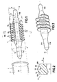
- This shuttle has a longitudinal axis 16.
- it comprises a shaft 14 disposed along the axis 16. It thus consists of two parts: an inner shaft 14 generally metallic or plastic, extending along its axis longitudinal 16 which is also its axis of displacement, and a polishing piece 15 of plastic.
- the shaft 14 made of rigid material ensures the maintenance and support of the polishing member 15 more flexible, and allows the manipulation thereof.
- the polishing shuttle has a form of revolution; it is more symmetrical with respect to its median plane PM perpendicular to its longitudinal axis. Because of this latter symmetry it can be used indifferently for a movement in one direction or the other.
- the shaft 14 has substantially the shape of a cylindrical bar. It has a reception portion in its middle part at which the polishing piece 15 is placed. This median part can be limited by two shoulders 17A and 17B ensuring the axial blocking of the polishing piece on the shaft 15.
- the increase in diameter at these shoulders should not be too large, to allow the polishing piece can be threaded onto the shaft 14 by passing over one of these.
- the polishing piece may have a generally cylindrical through bore which extends along its axis and through which the shaft 14 passes.
- the part 15 may more generally be attached to the shaft by any appropriate means, in particular being formed by overmoulding, which is compatible with both shoulders more marked than less marked, and with the absence of Shoulders, in particular when an internal connection is made between the shaft and the part 15, for example if they are made of compatible plastic materials.
- polishing piece 15 especially when the polishing piece 15 is attached to the shaft 14, it may be a reusable part, the polishing piece then being a wear part, a consumable part.
- gripping portions 11A and 11B On either side of the shoulders 17A and 17B respectively extend two substantially cylindrical gripping portions 11A and 11B. These gripping portions facilitate the handling of the polishing shuttle for use in a polishing device. In a more general manner any shape or structure allowing or facilitating the gripping can be used, whether for manipulation by pushing or pulling, and by mechanical means, by suction, or others.
- the outer surface of the polishing member 15 comprises radial projections 12, able to come into contact with the inner wall 2 of a polishing tube 1 when the shuttle is inside thereof.
- the projections are part of a cylindrical envelope 3, the diameter of which is slightly greater than that of the inner wall 2 of the tube to be polished.
- the radius (A) of the polishing piece including the projections and measured from the axis 16 of the shuttle must correspond substantially to the radius of the inner wall 2 of the polishing tube 1 and be slightly greater than that -this.
- the sections of these projections form a series of undulations separated from each other.
- the peak-to-peak height (B) of these undulations is greater than the distance (C) between two successive waves.
- the projections have substantially the shape of disks arranged one after the other along the longitudinal axis.
- the projections have a helical shape.
- a projection in a view along the axis of the shuttle, does not extend over 360 ° about the axis, but is divided or distributed on one or more radial angular sectors. In the latter case, it will advantageously ensure that projections axially cover the angular sectors left free by other projections, so that, taken together, the projections cover 360 °.
- the projections may have the shape of waves or have a substantially sinusoidal profile.
- the section width (E) of a projection may also be substantially constant or decrease as one moves away from the axis 16. Such a section width profile (E) decreasing facilitates in particular the manufacture of polishing parts by injection-molding because of the remains; it also gives good mechanical resistance to the polishing piece 15.
- the longitudinal section of the projections may have a width of section (E) average or median less than the height (B) peak-to-peak thereof, and even less than half thereof .
- the shuttle may comprise a metal shaft disposed along the axis thereof.
- projections 12 are overmolded on said shaft 14 and it is reusable.
- the projections generally constitute a single piece, in one piece, which can more particularly be overmolded on the shaft 14.
- the projections 12 and the shaft 14 may in another embodiment constitute a single piece.
- a longitudinal section of said projections it appears on at least one of said corrugations and substantially at the top thereof, at least one point contact zone 18 allowing a substantially punctual contact between the projection 12 and the tube to be polished. (the top of a ripple here designating the part of the latter furthest from the longitudinal axis).
- the almost punctual contact made by the area 18 of point contact with the inner wall of the tube to be polished is allowed by the fact that the radius of curvature R of the corrugation measured in its longitudinal section is small, in particular with respect to the width E of the projection section.
- the inner wall of the tube will be polished by making a relative movement between the shuttle and the tube to be polished, movement during which the shuttle passes from one end of said tube to the other through the tube. -this.
- the tube to be polished is maintained.
- the relative movement between the shuttle and the tube to be polished is then effected; this movement is a movement of the shuttle relative to the tube.
- the tube is released.
- a means such as in particular a tool 26 for holding tubes.
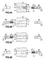
- a tube 24B is first put in place by means of supply and removal not shown.
- This polishing tube 24B is maintained for polishing in a holding passage 40 pierced through the tooling 26 and opening on two sides thereof 36A and 36B by two openings 36 and 38.
- This tube comprises a cylindrical portion whose inner cylindrical wall must be polished, and a flared collar forming a shoulder at one end 32 of the cylindrical portion.
- Maintaining the tube 24B in the holding passage 40 is on the one hand to the insertion of the cylindrical portion in the holding passage, but also to the abutment of the aforementioned shoulder of the tube against the 36B side of the tool 26, which prevents the tube from sinking into said holding passage 40 when the shuttle moves in the tube in the direction indicated by the arrow F.
- the Figure 4A presents the beginning of the polishing step.
- the shuttle 10 is retained by suction at the end of a pusher tool 20B, because it is evacuated or partially evacuated (arrow G) by means of suction and / or air compression. appropriate (V).
- the polishing shuttle is passed through the tube by pushing it through it.
- the pusher tool 20B moves in translation along the arrow F, and pushes the shuttle through the polishing tube 24B.
- the shuttle goes into the polishing tube 24B only once, in the only direction presented along arrow F, that is to say from a first end 32 of the tube towards its second end 34.
- the shuttle is thus passed through the tube by introducing it on a first side 36B of the tooling and then recovering it on another side 36A of the tooling.
- the recovery of the shuttle would be directly in the vicinity of the second end 34 of the tube.
- the movement of the shuttle relative to the polishing tube is thus a simple translation, inscribed along the axis of the tube. It is not necessary to provide more rotation.
- the projections of the shuttle extend over the entire circumference (360 °) of the inner wall of the tube to be polished, during the passage of the shuttle in the tube, the entire circumference of the inner wall of the tube is polished by a single passage in translation of the shuttle.
- the tube 24B thus polished can then be extracted from the tool 26 by pulling it in the direction opposite the arrow F, and transferred to the rest of the production line.
- the polishing device comprises a suction system and / or air compression V connected to the pusher tool 20A and used to recover the shuttles after passing through the tubes (arrow I).
- the pusher tool 20A advances near the opening on the side 36A of the holding passage, retrieves the shuttle by suction, and deviates from the tool (arrow H).
- the suction and / or air compression system comprises the air compression function
- the system can be used to subject the shuttle to an air pressure (compressed air) which will be used to propel through the polishing tube, for example during the step of process presented by the Figure 4A to propel the shuttle 10 in the direction of the arrow F towards the pusher tool 20A.
- the system for supplying and removing tubes removes the tube 24B, which is now polished, by pulling it in the direction opposite to the arrow F, as well as the installation of a new polishing tube 24A on the 36A side of the tool, the side on which is the shuttle.
- the figure 4C then presents the beginning of the polishing of the tube 24A in a manner similar to step 4A.
- the shuttle is initially retained in the pushing tool 20A by suction (arrow G ').
- the pusher tool 20A then advances in the direction symbolized by the arrow F 'to pass the shuttle in the tube 24A through the holding passage.
- the shuttle is recovered by the pusher tool 20B.
- the now polished tube 24A can then be deposited by the system (not shown) for supplying and removing tubes, and transferred to the stations downstream of the production line.
- the polishing process is carried out in a polishing device comprising several maintenance passages similar to the holding passage 40, arranged within the same carousel or barrel.
- the operations of placing and removing polishing and polished tubes respectively can be performed both in masked time and without risk of collision between the supply system and tube removal, on the one hand , and the manipulation system, on the other hand.
- the polishing device thus comprises a holding tool 126 for holding the tubes during polishing, a delivery and removal system which comprises, according to the embodiment shown, a system (52A, 53A, 52B, 53B) for supplying and removing polished and polished tubes respectively, and a handling system comprising pushing tools 120A and 120B located on either side of the tooling 126 .
- the tool 126 holding the tubes may be a carousel through which are pierced holding passages, for example three in number 131, 132, 133.
- the carousel may have a generally cylindrical shape or not, depending on the number of polished tubes at each cycle.
- the carousel is rotatable about an axis J.
- Each of the holding passages 131, 132 and 133 is open and capable of holding a tube to polish, and has a first opening opening on a first side of the tube holding tool, and a second opening opening on another side of the tooling.
- the carousel rotates about an axis moved by a not shown rotation system, for example electric or hydraulic.
- the carousel must stop successively in three positions, in which the holding passages 131, 132 and 133 are in alignment, respectively, with the axes K, L and M, to enable respectively the set-up, polishing and removal of polishing tubes.
- the pushing tools 120A and 120B are used to pass the shuttle 110 through the polishing tube, according to the method described above. They are evacuated by a vacuum system 54 creating a suction for securing and retaining the shuttle at the end of the pushing tools.
- the next cycle can then begin.
- a tube 124 will be put in place in the passage 131, the tube occupying the passage 133 will be polished, and the tube just polished and still maintained in the holding passage 132 will be deposited by the channel 53B deposition .
- the tooling for holding a polishing device according to the invention can be made in the form of a carousel or barrel and in different ways. It may for example include six holding passages.
- each holding passage can be operated in both directions for polishing the tube, the second opening acting as the first and vice versa.
- the polishing device according to the invention is particularly effective. Indeed in a device like that of the figure 5 each holding passage is successively operated in both directions for the successive polishing of tubes, the tubes to be polished successively fixed on each of the two sides of the holding tool 126, and the shuttle circulating alternately in each direction, polishing a tube during each pass.
- the system used for handling the shuttles is a pusher tool cooperating with the gripping portions located at the ends of the shuttle.
- the shuttle can adopt other forms allowing its handling (presence of holes, projections, co-operation systems of form), and other principles of mechanical handling can be adopted in particular by traction, possibly in combination with a rotation.
- the movement of the shuttle relative to the tube can be done using air pressure or suction, possibly in combination with a mechanical action of pushing and / or pulling as previously envisaged.
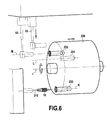
- the tube instead of providing that the tube is held fixed, and that the shuttle moves relative thereto during the polishing step, it may be the opposite, that is to say that during this step, it is the tube that moves with respect to the shuttle to carry out the polishing.
- a polishing shuttle before polishing the polishing tube, a polishing shuttle is maintained; the relative movement between the shuttle and the polishing tube is a movement of the tube relative to the shuttle; and after polishing the tube, the tube is released.
- Such a polishing device comprises a tool 220 holding shuttle capable of maintaining a shuttle during a polishing operation.
- the handling system comprises a supply and removal system (52, 53, 226) of the polished and polished tubes respectively, and is able to move the tube relative to the shuttle to carry out the polishing operation, said relative movement between the shuttle and the polishing tube being a movement of the tube relative to the shuttle.
- the tube supply and removal system therefore comprises a tube supply channel 52, a tube removal channel 53, and a tube holding and displacement tooling 226 comprising holding passages 231, 232, 233. which are blind cylindrical bores in the example shown.
- the tool 226 rotates 120 ° about its axis of rotation J.
- the shuttle is fixed on the holding tool 220, while the tube to be polished within the mobile tool 226 moves on the shuttle so as to allow the polishing of its inner wall.
- the advantage of the device presented by this figure is that it allows the polishing of closed tubes, unlike that presented by the figure 5 .
- the invention can also be exploited for polishing walls having openings, in particular slits, for example axial slots, shoulders or the like, provided however that the shape thereof and / or the latter does not prevent the passage of the shuttle.
- the invention may also be used not for polishing the entire length of the tube, but for only a portion of that length.
Landscapes
- Engineering & Computer Science (AREA)
- Mechanical Engineering (AREA)
- Physics & Mathematics (AREA)
- Fluid Mechanics (AREA)
- Finish Polishing, Edge Sharpening, And Grinding By Specific Grinding Devices (AREA)
- Grinding And Polishing Of Tertiary Curved Surfaces And Surfaces With Complex Shapes (AREA)
Applications Claiming Priority (1)
| Application Number | Priority Date | Filing Date | Title |
|---|---|---|---|
| FR0753259A FR2912336B1 (fr) | 2007-02-14 | 2007-02-14 | Navette de polissage, procede et dispositif de polissage utilisant celle-ci. |
Publications (2)
| Publication Number | Publication Date |
|---|---|
| EP1958731A1 true EP1958731A1 (de) | 2008-08-20 |
| EP1958731B1 EP1958731B1 (de) | 2013-05-15 |
Family
ID=38521690
Family Applications (1)
| Application Number | Title | Priority Date | Filing Date |
|---|---|---|---|
| EP08151342.6A Active EP1958731B1 (de) | 2007-02-14 | 2008-02-13 | Molch zum polieren der Rohrinnenseite, Verfahren und Vorrichtung zur Benutzung desgleichen |
Country Status (3)
| Country | Link |
|---|---|
| US (1) | US7959740B2 (de) |
| EP (1) | EP1958731B1 (de) |
| FR (1) | FR2912336B1 (de) |
Cited By (4)
| Publication number | Priority date | Publication date | Assignee | Title |
|---|---|---|---|---|
| WO2016018688A1 (en) * | 2014-07-30 | 2016-02-04 | Covidien Lp | Opening system for improving catheter delivery |
| FR3079431A1 (fr) * | 2018-03-27 | 2019-10-04 | Westair | Nettoyeur d’une tuyauterie |
| CN110774072A (zh) * | 2019-10-16 | 2020-02-11 | 衡水华锘光电科技有限公司 | 一种研磨夹具和直管内壁弧形研磨机 |
| EP3881947A1 (de) * | 2020-03-17 | 2021-09-22 | Martin Lembke | Verfahren zum reinigen des innenbereichs von rohren von lüftungs- und klimaanlagen |
Families Citing this family (13)
| Publication number | Priority date | Publication date | Assignee | Title |
|---|---|---|---|---|
| CN102225520B (zh) * | 2011-05-24 | 2013-03-20 | 清华大学 | 弯头修整装置及修整方法 |
| US8813770B2 (en) * | 2013-01-10 | 2014-08-26 | Chevron U.S.A. Inc. | Pig assembly and method for maintaining a functional line for conveying fluid |
| CN107571125A (zh) * | 2017-10-11 | 2018-01-12 | 安徽鑫艺达抛光机械有限公司 | 一种全自动罐体内壁抛光装置 |
| CN108359998B (zh) * | 2018-02-06 | 2023-11-24 | 上海神洲阳光特种钢管有限公司 | 一种环保型耐腐蚀精密冷轧不锈钢管后处理工艺 |
| JP1691374S (de) | 2019-11-01 | 2021-08-02 | ||
| CN111098219B (zh) * | 2020-01-17 | 2021-06-25 | 宁波金鼎紧固件有限公司 | 一种紧固件的压合垫片内外壁抛光机构 |
| WO2021260653A1 (en) * | 2020-06-25 | 2021-12-30 | IPH Limited | Cleaning device |
| CN112059763B (zh) * | 2020-08-21 | 2021-07-30 | 南京禹智智能科技有限公司 | 一种基于管材内壁抛光装置的抛光方法 |
| CN118575033A (zh) * | 2021-12-01 | 2024-08-30 | 赛诺菲-温思罗普工业公司 | 润滑梭 |
| CN118575034A (zh) * | 2021-12-01 | 2024-08-30 | 赛诺菲-温思罗普工业公司 | 润滑梭 |
| CN118541564A (zh) * | 2021-12-01 | 2024-08-23 | 赛诺菲-温思罗普工业公司 | 润滑梭 |
| WO2023099594A1 (en) * | 2021-12-01 | 2023-06-08 | Sanofi Winthrop Industrie | A lubricating shuttle |
| CN118081592B (zh) * | 2024-04-26 | 2024-07-30 | 烟台龙港泵业股份有限公司 | 一种离心泵散热机壳内壁抛光装置 |
Citations (8)
| Publication number | Priority date | Publication date | Assignee | Title |
|---|---|---|---|---|
| DE1031676B (de) * | 1954-04-23 | 1958-06-04 | Hildegard Schmidt Geb Supprian | Polierwerkzeug |
| FR73846E (fr) * | 1958-07-16 | 1960-09-12 | Disques de polissage | |
| FR2270057A1 (de) * | 1974-05-10 | 1975-12-05 | Rands Steve | |
| JPS513489A (en) * | 1974-06-29 | 1976-01-12 | Nippon Steel Corp | Kokanno naimenkensohoho |
| DE2743585A1 (de) * | 1977-09-28 | 1979-03-29 | Klaus Dipl Ing Groove | Chleifkoerper o.dgl. fuer rundschleifmaschinen |
| JPS55125965A (en) * | 1979-03-21 | 1980-09-29 | Teruhiko Yamazoe | Device for polishing inside surface of pipe |
| JPH02262947A (ja) * | 1989-03-31 | 1990-10-25 | Nisshin Steel Co Ltd | 小径管の内面研磨方法、装置および研磨玉 |
| JPH07266206A (ja) * | 1994-03-30 | 1995-10-17 | Olympus Optical Co Ltd | 管内面の研削研磨用工具 |
Family Cites Families (22)
| Publication number | Priority date | Publication date | Assignee | Title |
|---|---|---|---|---|
| US616696A (en) * | 1898-12-27 | Hose-cleaner | ||
| US864544A (en) * | 1906-04-24 | 1907-08-27 | Paul Kessler | Pipe and tube cleaner. |
| US1547440A (en) * | 1921-03-28 | 1925-07-28 | Warren C Drake | Tube-cleaning system |
| US2095823A (en) * | 1935-09-16 | 1937-10-12 | Marshall John | Coil and hose cleaner |
| US2763017A (en) * | 1953-03-16 | 1956-09-18 | Manus Ab | Device for cleaning milk conduits of machine milking plants |
| DE1994891U (de) * | 1968-07-03 | 1968-10-17 | Oscar Menzel Nachf Dr | Elastischer molch oder schaber, insbesondere fuer flexible leitungen. |
| US3857132A (en) * | 1972-11-24 | 1974-12-31 | K Knapp | Pipeline pig operable in two directions |
| US4069535A (en) * | 1973-05-30 | 1978-01-24 | Cato Bennie D | Pipeline pig |
| US3939519A (en) * | 1974-01-16 | 1976-02-24 | Muirhead Walter B | Condenser tube cleaning plug |
| US4083074A (en) * | 1976-12-16 | 1978-04-11 | Mustang Services Co. | Multipurpose pipeline pig |
| AU8236782A (en) * | 1981-04-08 | 1982-10-14 | Metropolitan Water Sewerage And Drainage Board, The | Pipe-cleaning device |
| US4425385A (en) * | 1982-04-12 | 1984-01-10 | Coulter-Mustang Services Company | Method for cleaning and coating pipeline walls |
| US4984322A (en) * | 1989-11-07 | 1991-01-15 | Tdw Delaware, Inc. | Elastomeric disc for use on a pipeline pig |
| US6038725A (en) * | 1996-03-29 | 2000-03-21 | Knapp; Kenneth M. | Unicast paraffin removing pipeline pig incorporating multiple diameter and thickness discs and having a central bending portion for turns |
| US5964004A (en) * | 1996-09-24 | 1999-10-12 | Bean; Douglas Colin | Device for cleaning medical endoscopic tubes |
| US6067682A (en) * | 1997-07-15 | 2000-05-30 | Tdw Delaware, Inc. | Cup or disc for use as a part of a pipeline pig |
| FR2769250B1 (fr) * | 1997-10-07 | 1999-11-05 | Servinox Soc Nouv | Dispositif perfectionne pour le raclage d'une conduite |
| BR9802190A (pt) * | 1998-06-23 | 2000-04-11 | Petroleo Brasileiro Sa | Dispositivo raspador multidimensional bidirecional modular. |
| GB9814579D0 (en) * | 1998-07-07 | 1998-09-02 | Suttie Walter R | Pipeline pig |
| AUPP537098A0 (en) * | 1998-08-20 | 1998-09-10 | Novapharm Research (Australia) Pty Ltd | Endoscope cleaning device |
| US6145150A (en) * | 1999-01-05 | 2000-11-14 | Knapp; Kenneth M. | Multi-dimensional pig including wiper disk permitting passage through |
| GB9907619D0 (en) * | 1999-04-06 | 1999-05-26 | Suttie Walter R | Pipeline pigging apparatus |
-
2007
- 2007-02-14 FR FR0753259A patent/FR2912336B1/fr active Active
-
2008
- 2008-02-13 EP EP08151342.6A patent/EP1958731B1/de active Active
- 2008-02-14 US US12/031,663 patent/US7959740B2/en active Active
Patent Citations (8)
| Publication number | Priority date | Publication date | Assignee | Title |
|---|---|---|---|---|
| DE1031676B (de) * | 1954-04-23 | 1958-06-04 | Hildegard Schmidt Geb Supprian | Polierwerkzeug |
| FR73846E (fr) * | 1958-07-16 | 1960-09-12 | Disques de polissage | |
| FR2270057A1 (de) * | 1974-05-10 | 1975-12-05 | Rands Steve | |
| JPS513489A (en) * | 1974-06-29 | 1976-01-12 | Nippon Steel Corp | Kokanno naimenkensohoho |
| DE2743585A1 (de) * | 1977-09-28 | 1979-03-29 | Klaus Dipl Ing Groove | Chleifkoerper o.dgl. fuer rundschleifmaschinen |
| JPS55125965A (en) * | 1979-03-21 | 1980-09-29 | Teruhiko Yamazoe | Device for polishing inside surface of pipe |
| JPH02262947A (ja) * | 1989-03-31 | 1990-10-25 | Nisshin Steel Co Ltd | 小径管の内面研磨方法、装置および研磨玉 |
| JPH07266206A (ja) * | 1994-03-30 | 1995-10-17 | Olympus Optical Co Ltd | 管内面の研削研磨用工具 |
Cited By (6)
| Publication number | Priority date | Publication date | Assignee | Title |
|---|---|---|---|---|
| WO2016018688A1 (en) * | 2014-07-30 | 2016-02-04 | Covidien Lp | Opening system for improving catheter delivery |
| US10258764B2 (en) | 2014-07-30 | 2019-04-16 | Covidien Lp | Opening system for improving catheter delivery |
| FR3079431A1 (fr) * | 2018-03-27 | 2019-10-04 | Westair | Nettoyeur d’une tuyauterie |
| EP3549685A1 (de) * | 2018-03-27 | 2019-10-09 | Westair | Reiniger für rohre |
| CN110774072A (zh) * | 2019-10-16 | 2020-02-11 | 衡水华锘光电科技有限公司 | 一种研磨夹具和直管内壁弧形研磨机 |
| EP3881947A1 (de) * | 2020-03-17 | 2021-09-22 | Martin Lembke | Verfahren zum reinigen des innenbereichs von rohren von lüftungs- und klimaanlagen |
Also Published As
| Publication number | Publication date |
|---|---|
| US7959740B2 (en) | 2011-06-14 |
| FR2912336A1 (fr) | 2008-08-15 |
| FR2912336B1 (fr) | 2009-08-28 |
| US20080200101A1 (en) | 2008-08-21 |
| EP1958731B1 (de) | 2013-05-15 |
Similar Documents
| Publication | Publication Date | Title |
|---|---|---|
| EP1958731B1 (de) | Molch zum polieren der Rohrinnenseite, Verfahren und Vorrichtung zur Benutzung desgleichen | |
| EP2332716B1 (de) | Vorrichtung für Aufdehnwerkzeug für Zange auf der Maschine, zum Ausführen von Fugen an den Endstücken von Plastik- oder Verbundrohren | |
| FR2855565A1 (fr) | Pompe a engrenages a denture en chevrons | |
| FR2473152A1 (fr) | Dispositif de couplage deconnectable pour un tuyau | |
| BE1021544B1 (fr) | Dispositif de fabrication de brosses, et brosse fabriquee a l'aide dudit dispositif | |
| EP3210746A1 (de) | Vorrichtung zum entformen mittels kettenartige verbundener elemente | |
| FR2744205A1 (fr) | Echangeur de chaleur et machine pour le montage d'un tel echangeur | |
| EP3319667B1 (de) | Spritze und verfahren zur montage davon | |
| FR2863188A1 (fr) | Mandrin | |
| EP3670992B1 (de) | Anschlussbuchse und fluidanschluss, der ein steckanschlusselement sowie diese anschlussbuchse umfasst | |
| FR2788466A1 (fr) | Outil de moulage par injection pour la fabrication d'une cage de roulement lineaire, et cage moulee par injection pour un roulement lineaire | |
| CA2253422A1 (fr) | Brosse a dents dont le manche comporte des moyens pour son rangement en position verticale | |
| EP4166836B1 (de) | Schnellkupplung und verbindungsanordnung mit einer solchen schnellkupplung | |
| WO2020249898A1 (fr) | Module de dépose pour tête de dépose de tronçons de bande de fibres pour la réalisation de pièce en matériaux composites, tête de dépose, robot de dépose, et procédé de dépose | |
| EP1315930B1 (de) | Schnellverbindungsstück | |
| EP2032314B1 (de) | Werkzeug zur montage einer dichtung in einer rinne, insbesondere für eine wasserstrahl-projektionsvorrichtung | |
| FR3065668B1 (fr) | Dispositif pour fabriquer des recipients pourvus de banderoles de decor | |
| EP2461719B1 (de) | Bürste zur reinigung eines containers | |
| EP2032315B1 (de) | Plattformwerkzeug zur montage einer dichtung in einer rinne, insbesondere für eine wasserstrahl-projektionsvorrichtung | |
| FR3144764A1 (fr) | Système de retrait d’étiquettes adhésives de contenants, machine de traitement de contenants et procédé de retrait d’étiquettes associés | |
| EP3019326A1 (de) | Einheit zum formen von behältern aus einem thermoplastischen kunststoff mit kompensationsvorrichtung | |
| WO2020249897A1 (fr) | Module de découpe pour tête de dépose de tronçons de bande de fibres pour la réalisation de pièce en matériaux composites, tête de dépose, robot de dépose et procédé de découpe et procédé de dépose | |
| FR3097156A1 (fr) | Module d’alimentation pour tête de dépose de tronçons de bande de fibres pour la réalisation de pièce en matériaux composites, tête de dépose, robot de dépose et procédé d’alimentation et procédé de dépose. | |
| FR2843625A1 (fr) | Dispositif de branchement d'alimentation pour un systeme a pression de fluide | |
| FR2885549A1 (fr) | Procede de fabrication d'un coussin comportant une decoupe, et dispositif pour la mise en oeuvre d'un tel procede |
Legal Events
| Date | Code | Title | Description |
|---|---|---|---|
| PUAI | Public reference made under article 153(3) epc to a published international application that has entered the european phase |
Free format text: ORIGINAL CODE: 0009012 |
|
| AK | Designated contracting states |
Kind code of ref document: A1 Designated state(s): AT BE BG CH CY CZ DE DK EE ES FI FR GB GR HR HU IE IS IT LI LT LU LV MC MT NL NO PL PT RO SE SI SK TR |
|
| AX | Request for extension of the european patent |
Extension state: AL BA MK RS |
|
| 17P | Request for examination filed |
Effective date: 20090127 |
|
| RIN1 | Information on inventor provided before grant (corrected) |
Inventor name: CHEVALLIER, STEPHANE |
|
| 17Q | First examination report despatched |
Effective date: 20090317 |
|
| AKX | Designation fees paid |
Designated state(s): AT BE BG CH CY CZ DE DK EE ES FI FR GB GR HR HU IE IS IT LI LT LU LV MC MT NL NO PL PT RO SE SI SK TR |
|
| RAP1 | Party data changed (applicant data changed or rights of an application transferred) |
Owner name: TECH GROUP EUROPE LIMITED |
|
| RIC1 | Information provided on ipc code assigned before grant |
Ipc: B24D 15/04 20060101ALI20101109BHEP Ipc: B24D 13/02 20060101ALI20101109BHEP Ipc: B24B 39/02 20060101AFI20101109BHEP Ipc: B24B 5/40 20060101ALI20101109BHEP |
|
| REG | Reference to a national code |
Ref country code: DE Ref legal event code: R079 Ref document number: 602008024533 Country of ref document: DE Free format text: PREVIOUS MAIN CLASS: B24B0005400000 Ipc: B08B0009055000 |
|
| GRAP | Despatch of communication of intention to grant a patent |
Free format text: ORIGINAL CODE: EPIDOSNIGR1 |
|
| RIC1 | Information provided on ipc code assigned before grant |
Ipc: B08B 9/055 20060101AFI20121114BHEP Ipc: B24D 13/08 20060101ALI20121114BHEP Ipc: B24B 39/02 20060101ALI20121114BHEP Ipc: B24D 13/02 20060101ALI20121114BHEP Ipc: B24B 5/40 20060101ALI20121114BHEP Ipc: B24D 15/04 20060101ALI20121114BHEP |
|
| GRAS | Grant fee paid |
Free format text: ORIGINAL CODE: EPIDOSNIGR3 |
|
| GRAA | (expected) grant |
Free format text: ORIGINAL CODE: 0009210 |
|
| AK | Designated contracting states |
Kind code of ref document: B1 Designated state(s): AT BE BG CH CY CZ DE DK EE ES FI FR GB GR HR HU IE IS IT LI LT LU LV MC MT NL NO PL PT RO SE SI SK TR |
|
| REG | Reference to a national code |
Ref country code: GB Ref legal event code: FG4D Free format text: NOT ENGLISH Ref country code: CH Ref legal event code: EP |
|
| REG | Reference to a national code |
Ref country code: AT Ref legal event code: REF Ref document number: 611860 Country of ref document: AT Kind code of ref document: T Effective date: 20130615 |
|
| REG | Reference to a national code |
Ref country code: IE Ref legal event code: FG4D Free format text: LANGUAGE OF EP DOCUMENT: FRENCH |
|
| REG | Reference to a national code |
Ref country code: DE Ref legal event code: R096 Ref document number: 602008024533 Country of ref document: DE Effective date: 20130711 |
|
| REG | Reference to a national code |
Ref country code: AT Ref legal event code: MK05 Ref document number: 611860 Country of ref document: AT Kind code of ref document: T Effective date: 20130515 |
|
| REG | Reference to a national code |
Ref country code: LT Ref legal event code: MG4D |
|
| REG | Reference to a national code |
Ref country code: NL Ref legal event code: VDEP Effective date: 20130515 |
|
| PG25 | Lapsed in a contracting state [announced via postgrant information from national office to epo] |
Ref country code: FI Free format text: LAPSE BECAUSE OF FAILURE TO SUBMIT A TRANSLATION OF THE DESCRIPTION OR TO PAY THE FEE WITHIN THE PRESCRIBED TIME-LIMIT Effective date: 20130515 Ref country code: ES Free format text: LAPSE BECAUSE OF FAILURE TO SUBMIT A TRANSLATION OF THE DESCRIPTION OR TO PAY THE FEE WITHIN THE PRESCRIBED TIME-LIMIT Effective date: 20130826 Ref country code: SI Free format text: LAPSE BECAUSE OF FAILURE TO SUBMIT A TRANSLATION OF THE DESCRIPTION OR TO PAY THE FEE WITHIN THE PRESCRIBED TIME-LIMIT Effective date: 20130515 Ref country code: PT Free format text: LAPSE BECAUSE OF FAILURE TO SUBMIT A TRANSLATION OF THE DESCRIPTION OR TO PAY THE FEE WITHIN THE PRESCRIBED TIME-LIMIT Effective date: 20130916 Ref country code: LT Free format text: LAPSE BECAUSE OF FAILURE TO SUBMIT A TRANSLATION OF THE DESCRIPTION OR TO PAY THE FEE WITHIN THE PRESCRIBED TIME-LIMIT Effective date: 20130515 Ref country code: GR Free format text: LAPSE BECAUSE OF FAILURE TO SUBMIT A TRANSLATION OF THE DESCRIPTION OR TO PAY THE FEE WITHIN THE PRESCRIBED TIME-LIMIT Effective date: 20130816 Ref country code: NO Free format text: LAPSE BECAUSE OF FAILURE TO SUBMIT A TRANSLATION OF THE DESCRIPTION OR TO PAY THE FEE WITHIN THE PRESCRIBED TIME-LIMIT Effective date: 20130815 Ref country code: IS Free format text: LAPSE BECAUSE OF FAILURE TO SUBMIT A TRANSLATION OF THE DESCRIPTION OR TO PAY THE FEE WITHIN THE PRESCRIBED TIME-LIMIT Effective date: 20130915 Ref country code: SE Free format text: LAPSE BECAUSE OF FAILURE TO SUBMIT A TRANSLATION OF THE DESCRIPTION OR TO PAY THE FEE WITHIN THE PRESCRIBED TIME-LIMIT Effective date: 20130515 Ref country code: AT Free format text: LAPSE BECAUSE OF FAILURE TO SUBMIT A TRANSLATION OF THE DESCRIPTION OR TO PAY THE FEE WITHIN THE PRESCRIBED TIME-LIMIT Effective date: 20130515 |
|
| PG25 | Lapsed in a contracting state [announced via postgrant information from national office to epo] |
Ref country code: PL Free format text: LAPSE BECAUSE OF FAILURE TO SUBMIT A TRANSLATION OF THE DESCRIPTION OR TO PAY THE FEE WITHIN THE PRESCRIBED TIME-LIMIT Effective date: 20130515 Ref country code: BG Free format text: LAPSE BECAUSE OF FAILURE TO SUBMIT A TRANSLATION OF THE DESCRIPTION OR TO PAY THE FEE WITHIN THE PRESCRIBED TIME-LIMIT Effective date: 20130815 Ref country code: HR Free format text: LAPSE BECAUSE OF FAILURE TO SUBMIT A TRANSLATION OF THE DESCRIPTION OR TO PAY THE FEE WITHIN THE PRESCRIBED TIME-LIMIT Effective date: 20130515 |
|
| PG25 | Lapsed in a contracting state [announced via postgrant information from national office to epo] |
Ref country code: LV Free format text: LAPSE BECAUSE OF FAILURE TO SUBMIT A TRANSLATION OF THE DESCRIPTION OR TO PAY THE FEE WITHIN THE PRESCRIBED TIME-LIMIT Effective date: 20130515 |
|
| PG25 | Lapsed in a contracting state [announced via postgrant information from national office to epo] |
Ref country code: CZ Free format text: LAPSE BECAUSE OF FAILURE TO SUBMIT A TRANSLATION OF THE DESCRIPTION OR TO PAY THE FEE WITHIN THE PRESCRIBED TIME-LIMIT Effective date: 20130515 Ref country code: EE Free format text: LAPSE BECAUSE OF FAILURE TO SUBMIT A TRANSLATION OF THE DESCRIPTION OR TO PAY THE FEE WITHIN THE PRESCRIBED TIME-LIMIT Effective date: 20130515 Ref country code: DK Free format text: LAPSE BECAUSE OF FAILURE TO SUBMIT A TRANSLATION OF THE DESCRIPTION OR TO PAY THE FEE WITHIN THE PRESCRIBED TIME-LIMIT Effective date: 20130515 Ref country code: SK Free format text: LAPSE BECAUSE OF FAILURE TO SUBMIT A TRANSLATION OF THE DESCRIPTION OR TO PAY THE FEE WITHIN THE PRESCRIBED TIME-LIMIT Effective date: 20130515 |
|
| PG25 | Lapsed in a contracting state [announced via postgrant information from national office to epo] |
Ref country code: NL Free format text: LAPSE BECAUSE OF FAILURE TO SUBMIT A TRANSLATION OF THE DESCRIPTION OR TO PAY THE FEE WITHIN THE PRESCRIBED TIME-LIMIT Effective date: 20130515 Ref country code: IT Free format text: LAPSE BECAUSE OF FAILURE TO SUBMIT A TRANSLATION OF THE DESCRIPTION OR TO PAY THE FEE WITHIN THE PRESCRIBED TIME-LIMIT Effective date: 20130515 Ref country code: RO Free format text: LAPSE BECAUSE OF FAILURE TO SUBMIT A TRANSLATION OF THE DESCRIPTION OR TO PAY THE FEE WITHIN THE PRESCRIBED TIME-LIMIT Effective date: 20130515 |
|
| PLBE | No opposition filed within time limit |
Free format text: ORIGINAL CODE: 0009261 |
|
| STAA | Information on the status of an ep patent application or granted ep patent |
Free format text: STATUS: NO OPPOSITION FILED WITHIN TIME LIMIT |
|
| 26N | No opposition filed |
Effective date: 20140218 |
|
| REG | Reference to a national code |
Ref country code: DE Ref legal event code: R097 Ref document number: 602008024533 Country of ref document: DE Effective date: 20140218 |
|
| BERE | Be: lapsed |
Owner name: TECH GROUP EUROPE LIMITED Effective date: 20140228 |
|
| PG25 | Lapsed in a contracting state [announced via postgrant information from national office to epo] |
Ref country code: MC Free format text: LAPSE BECAUSE OF FAILURE TO SUBMIT A TRANSLATION OF THE DESCRIPTION OR TO PAY THE FEE WITHIN THE PRESCRIBED TIME-LIMIT Effective date: 20130515 Ref country code: LU Free format text: LAPSE BECAUSE OF FAILURE TO SUBMIT A TRANSLATION OF THE DESCRIPTION OR TO PAY THE FEE WITHIN THE PRESCRIBED TIME-LIMIT Effective date: 20140213 |
|
| REG | Reference to a national code |
Ref country code: CH Ref legal event code: PL |
|
| GBPC | Gb: european patent ceased through non-payment of renewal fee |
Effective date: 20140213 |
|
| PG25 | Lapsed in a contracting state [announced via postgrant information from national office to epo] |
Ref country code: LI Free format text: LAPSE BECAUSE OF NON-PAYMENT OF DUE FEES Effective date: 20140228 Ref country code: CH Free format text: LAPSE BECAUSE OF NON-PAYMENT OF DUE FEES Effective date: 20140228 |
|
| REG | Reference to a national code |
Ref country code: IE Ref legal event code: MM4A |
|
| PG25 | Lapsed in a contracting state [announced via postgrant information from national office to epo] |
Ref country code: IE Free format text: LAPSE BECAUSE OF NON-PAYMENT OF DUE FEES Effective date: 20140213 Ref country code: GB Free format text: LAPSE BECAUSE OF NON-PAYMENT OF DUE FEES Effective date: 20140213 Ref country code: BE Free format text: LAPSE BECAUSE OF NON-PAYMENT OF DUE FEES Effective date: 20140228 |
|
| REG | Reference to a national code |
Ref country code: FR Ref legal event code: PLFP Year of fee payment: 9 |
|
| PG25 | Lapsed in a contracting state [announced via postgrant information from national office to epo] |
Ref country code: MT Free format text: LAPSE BECAUSE OF FAILURE TO SUBMIT A TRANSLATION OF THE DESCRIPTION OR TO PAY THE FEE WITHIN THE PRESCRIBED TIME-LIMIT Effective date: 20130515 |
|
| PG25 | Lapsed in a contracting state [announced via postgrant information from national office to epo] |
Ref country code: CY Free format text: LAPSE BECAUSE OF FAILURE TO SUBMIT A TRANSLATION OF THE DESCRIPTION OR TO PAY THE FEE WITHIN THE PRESCRIBED TIME-LIMIT Effective date: 20130515 |
|
| PG25 | Lapsed in a contracting state [announced via postgrant information from national office to epo] |
Ref country code: HU Free format text: LAPSE BECAUSE OF FAILURE TO SUBMIT A TRANSLATION OF THE DESCRIPTION OR TO PAY THE FEE WITHIN THE PRESCRIBED TIME-LIMIT; INVALID AB INITIO Effective date: 20080213 Ref country code: TR Free format text: LAPSE BECAUSE OF FAILURE TO SUBMIT A TRANSLATION OF THE DESCRIPTION OR TO PAY THE FEE WITHIN THE PRESCRIBED TIME-LIMIT Effective date: 20130515 |
|
| REG | Reference to a national code |
Ref country code: FR Ref legal event code: PLFP Year of fee payment: 10 |
|
| REG | Reference to a national code |
Ref country code: FR Ref legal event code: PLFP Year of fee payment: 11 |
|
| P01 | Opt-out of the competence of the unified patent court (upc) registered |
Effective date: 20230529 |
|
| PGFP | Annual fee paid to national office [announced via postgrant information from national office to epo] |
Ref country code: DE Payment date: 20240228 Year of fee payment: 17 |
|
| PGFP | Annual fee paid to national office [announced via postgrant information from national office to epo] |
Ref country code: FR Payment date: 20240226 Year of fee payment: 17 |