EP1958701A1 - Spray nozzle with inverted water flow - Google Patents
Spray nozzle with inverted water flow Download PDFInfo
- Publication number
- EP1958701A1 EP1958701A1 EP08002533A EP08002533A EP1958701A1 EP 1958701 A1 EP1958701 A1 EP 1958701A1 EP 08002533 A EP08002533 A EP 08002533A EP 08002533 A EP08002533 A EP 08002533A EP 1958701 A1 EP1958701 A1 EP 1958701A1
- Authority
- EP
- European Patent Office
- Prior art keywords
- nozzle
- spray nozzle
- fluid
- water
- upward
- Prior art date
- Legal status (The legal status is an assumption and is not a legal conclusion. Google has not performed a legal analysis and makes no representation as to the accuracy of the status listed.)
- Withdrawn
Links
Images


Classifications
-
- B—PERFORMING OPERATIONS; TRANSPORTING
- B05—SPRAYING OR ATOMISING IN GENERAL; APPLYING FLUENT MATERIALS TO SURFACES, IN GENERAL
- B05B—SPRAYING APPARATUS; ATOMISING APPARATUS; NOZZLES
- B05B1/00—Nozzles, spray heads or other outlets, with or without auxiliary devices such as valves, heating means
- B05B1/26—Nozzles, spray heads or other outlets, with or without auxiliary devices such as valves, heating means with means for mechanically breaking-up or deflecting the jet after discharge, e.g. with fixed deflectors; Breaking-up the discharged liquid or other fluent material by impinging jets
- B05B1/262—Nozzles, spray heads or other outlets, with or without auxiliary devices such as valves, heating means with means for mechanically breaking-up or deflecting the jet after discharge, e.g. with fixed deflectors; Breaking-up the discharged liquid or other fluent material by impinging jets with fixed deflectors
- B05B1/265—Nozzles, spray heads or other outlets, with or without auxiliary devices such as valves, heating means with means for mechanically breaking-up or deflecting the jet after discharge, e.g. with fixed deflectors; Breaking-up the discharged liquid or other fluent material by impinging jets with fixed deflectors the liquid or other fluent material being symmetrically deflected about the axis of the nozzle
-
- B—PERFORMING OPERATIONS; TRANSPORTING
- B05—SPRAYING OR ATOMISING IN GENERAL; APPLYING FLUENT MATERIALS TO SURFACES, IN GENERAL
- B05B—SPRAYING APPARATUS; ATOMISING APPARATUS; NOZZLES
- B05B1/00—Nozzles, spray heads or other outlets, with or without auxiliary devices such as valves, heating means
- B05B1/26—Nozzles, spray heads or other outlets, with or without auxiliary devices such as valves, heating means with means for mechanically breaking-up or deflecting the jet after discharge, e.g. with fixed deflectors; Breaking-up the discharged liquid or other fluent material by impinging jets
- B05B1/262—Nozzles, spray heads or other outlets, with or without auxiliary devices such as valves, heating means with means for mechanically breaking-up or deflecting the jet after discharge, e.g. with fixed deflectors; Breaking-up the discharged liquid or other fluent material by impinging jets with fixed deflectors
- B05B1/267—Nozzles, spray heads or other outlets, with or without auxiliary devices such as valves, heating means with means for mechanically breaking-up or deflecting the jet after discharge, e.g. with fixed deflectors; Breaking-up the discharged liquid or other fluent material by impinging jets with fixed deflectors the liquid or other fluent material being deflected in determined directions
Definitions
- This invention relates to an irrigation spray nozzle and, more particularly, to a spray nozzle with an inverted water flow.
- Irrigation nozzles have been adapted for mounting on a fixed or pop-up water supply riser.
- Spray type irrigation nozzles typically include at least one discharge orifice shaped to distribute water in a stream or spray pattern of a pre-selected arcuate span.
- One common form of such spray nozzle includes an upper deflector assembled to a lower nozzle body designed for mounting onto the riser. The deflector and nozzle body cooperatively define the discharge orifice with the selected arcuate span through which water is projected from the nozzle.
- Such spray nozzles commonly include a series of models that each produce a different spray pattern, such as, for example, a quarter-circle, half-circle, and full-circle spray pattern.
- the water stream is generally comprised of two portions: an upper portion and a lower portion.
- the upper portion of the stream typically has a relatively low velocity because it has experienced frictional drag across the deflector.
- the lower portion of the stream generally has a relatively high velocity because it has not experienced this frictional drag.
- gravity causes the lower velocity water to interfere with the higher velocity water, resulting in an intermediate velocity water stream that irrigates with only a mid-range doughnut pattern about the nozzle.
- FIG. 1 is a perspective view of a spray nozzle embodying features of the present invention
- FIG. 2 is a cross-sectional view taken along line 2-2 of FIG.1 ;
- FIG. 3 is another cross-sectional view taken along line 3-3 of FIG. 1 ;
- FIG. 4 is a perspective view of a nozzle base of the spray nozzle of FIG. 1 ;
- FIG. 5 is a perspective view of a first embodiment of a nozzle body for the spray nozzle of FIG. 1 ;
- FIG. 6 is a perspective view of a second embodiment of a nozzle body for the spray nozzle of FIG. 1 ;
- FIG. 7 is a perspective view of a third embodiment of a nozzle body for the spray nozzle of FIG. 1 ;
- FIG. 8 is a perspective view of a first embodiment of a cover for the spray nozzle of FIG. 1 ;
- FIG. 9 is a perspective view of a second embodiment of a cover for the spray nozzle of FIG. 1 ;
- FIG. 10 is a perspective view of a third embodiment of a cover for the spray nozzle of FIG. 1 ;
- FIG. 11 is an exploded view of a side strip spray nozzle embodying features of the present invention.
- FIG. 12 is a perspective view of a nozzle base for the side strip spray nozzle of FIG. 11 ;
- FIG. 13 is a perspective view of a nozzle body for the side strip spray nozzle of FIG. 11 ;
- FIG. 14 is a perspective view of a cover for the side strip spray nozzle of FIG. 11 ;
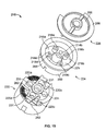
- FIG. 15 is an exploded view of a corner strip spray nozzle embodying features of the present invention.
- FIG. 16 is a perspective view of a nozzle base for the corner strip spray nozzle of FIG. 15 ;
- FIG. 17 is a perspective view of a nozzle body for the corner strip spray nozzle of FIG. 15 ;
- FIG. 18 is a bottom view of a cover for the corner strip spray nozzle of FIG. 15 .
- a spray nozzle 10 embodying features of the present invention.
- the nozzle 10 improves the flow pattern at the inner and outer regions of the spray coverage by using a downward flow directed at a deflector 12 of the nozzle 10, as opposed to the upward flow at the deflector used in conventional spray nozzles.
- the inverted nature of the downward flow onto the deflector 12 results in a more uniform distribution of water, when compared to an upward flow nozzle, because the lower flow velocity component of the water discharging from the nozzle 10 cannot interfere directly with or fall into the higher velocity component. That is, the lower component is now at the bottom portion of the discharging water, and thus, the higher velocity component sprays generally above the lower velocity component. Consequently, the higher velocity component provides both a longer throw, which increases the watering area, and an improved watering at the outer region, and the lower velocity component waters the inner region more effectively.
- the inverted pattern is created by channeling the supply water first toward the top of the nozzle 10 and then back down to the deflector 12. That is, a series of upward flow passages 14 channels the water initially to a chamber 16 above the deflector 12. The water then flows from the chamber 16 through a series of downward flow passages 18 onto a top surface 20 of the deflector 12 to be redirected outward from the nozzle 10 for irrigation. Inverting the direction at the deflector 12 causes the high and low velocity components to switch as well.
- the nozzle 10 preferably includes a nozzle base 22, a nozzle body 24, and a nozzle cover 26, which, together, define the upward and downward flow passages 14 and 18, the chamber 16, and one or more deflector surfaces 20 of the nozzle 10.
- These components preferably are formed of a molded plastic material, or other suitable material, and although they are shown as three separate parts, they also may be combined to form one part or two parts.
- the nozzle base 22 is generally cylindrical in shape with a generally closed upper end 28 and an open lower mounting end 30.
- the lower mounting end 30 includes internal threading 32 for mounting of the nozzle 10 with corresponding external threading on an end of piping, such as a riser, supplying water.
- the nozzle base 22 also defines a central bore 34 to receive a flow throttling screw 36 to provide for adjustment of the inflow of water into the nozzle 10. Threading 38 is provided at the central bore 34 to cooperate with threading on the screw 36 to enable movement of the screw 36.
- the upper end 28 of the nozzle base 22 also defines one or more flow passages 31 for the flow of water vertically upward from the water source and through the nozzle base 22.
- the nozzle base 22 further includes one or more deflector surfaces 20.
- the flow passages 31 extend through seats 40 that define a top seating surface 42, which is elevated with respect to the deflector surfaces 20.
- the nozzle base 22 provides upward water flow and deflects water directed downward from the chamber 16 against the deflector surfaces 20 outward from the nozzle 10.
- the deflector surfaces 20 are generally concave in shape in the radial direction.
- Each surface 20 includes an inner portion 44 and an outer portion 46.
- the inner portion 44 is closer to the central axis of the nozzle base 22 and has an outer perimeter defined by the intersection of the edges 48 of two adjacent raised seats 40. Moving radially outward, the inner portion 44 slopes relatively steeply downwardly to a nadir and, then, slopes relatively gently upwardly to transition into the outer portion 46.
- the outer portion 46 terminates with a number of radial extending drag-inducing grooves 50 about the outer periphery of the deflector surface 20. This concave geometry of the deflector surfaces 20 enhances uniform water distribution, as discussed further below.
- FIGS. 5-7 there are illustrated three different forms of the nozzle body 24a, 24b, 24c.
- Each different nozzle body 24a-c produces an irrigation pattern for a different sized arcuate region. That is, nozzle body 24a ( FIG. 5 ) produces 90 degree arc of coverage (quarter-circle); nozzle body 24b ( FIG. 6 ) produces a 180 degree arc of coverage (half-circle); and nozzle body 24c ( FIG. 7 ) produces a 360 degree arc of coverage (full-circle).
- Each nozzle body 24a-c preferably is generally cylindrical in shape and is seated vertically atop, and in fluid communication with, the nozzle base 22 and has two sets of flow passages: an upward set 14 for water flow upward through the nozzle body 24 and a downward set 18 for water flow downward through the nozzle body 24.
- the nozzle cover 26 and the nozzle body 24 together define the chamber 16, which places the upward flow passages 14 in fluid communication with the downward flow passages 18
- the upward flow passages 14 are connected to the flow passages 31 of the nozzle base 22 so that water travels vertically upwardly from the nozzle base 22 through the flow passages 31 and, then, through the upward flow passages 14 to the chamber 16.
- Each of the upward flow passages 14 is tube-like and extends into one of the flow passages 31 with the outer surface of the tube 52 engaging the inner surface of the flow passage 31 to form a sealed connection.
- the number of downward flow passages 18 corresponds to the size of the desired water distribution arc.
- the nozzle body 24a of FIG. 5 (quarter-circle) defines one downward flow passage 18
- the nozzle body 24b of FIG. 6 (half-circle) defines two downward flow passages 18
- the nozzle body 24c of FIG. 7 (full-circle) defines four downward flow passages 18.
- each of the downward flow passages 18 is defined by an upwardly projecting cylindrical tube 54 that is positioned above and vertically spaced from one of the deflector surfaces 20 of the nozzle base 22.
- the tubes 54 function to direct water downwardly against the respective deflector surfaces 20 to reduce or eliminate tangential components of flow as compared to a mere opening without the tube portion. Tangential components of flow, i.e., flows that impact the deflector surfaces 12 at one or more of a range of angles different than generally vertical, can disadvantageously result in interfering water streams and a non-uniform distribution of water at different distances from the nozzle 10.
- Each nozzle body 24a-c defines a central opening 56 therethrough which cooperates with a cover 26, as described further below.
- Each nozzle body 24a-b includes one or more arcuate tabs 60 that project downward from a portion of the outer periphery of the nozzle body 24a-b. Each tab 60 engages a landing 62 formed at the outer periphery of each deflector surface 20 between adjacent seats 40.
- the number and arrangement of arcuate tabs 60 indicate the nature of the nozzle 10, i.e., the three tabs 60 of nozzle body 24a of FIG. 5 corresponds to a quarter-circle nozzle, the two tabs 60 of the nozzle body 24b of FIG. 6 corresponds to a half-circle nozzle, and the lack of any tabs on the nozzle body 24c of FIG. 7 corresponds to a full-circle nozzle.
- the arcuate tabs 60 also indicate the direction of spray from the nozzle 10 by eliminating the arcuate gap 64 between the nozzle base 22 and the nozzle body 24 at deflector surfaces 20 where water is not being emitted.
- each cover 26 includes a disk-like top surface 66 that indicates the nature of the nozzle 10, i.e., quarter ( FIG. 8 ), half ( FIG. 9 ), or full ( FIG. 10 ), and the direction of spray from the nozzle 10.
- the cover 26a of FIG. 8 has approximately one-fourth of the outer circumference of the top surface 66 indented with a reduced diameter, indicating that the nozzle 10 is a quarter-circle nozzle and indicating that spray is in the direction of the indented portion.
- the cover 26c of FIG. 10 has the entire outer circumference of the top surface 66 indented with a reduced diameter, identifying the nozzle 10 as a full-circle nozzle and indicating that spray is emitted in the full 360 degrees of arc.
- the cover 26 sits on top of the nozzle body 24.
- the cover 26 cooperates with the nozzle body 24 to define the chamber 16.
- the chamber 16 places the upward flow passages 14 in fluid communication with the downward flow passages 18.
- the cover 26 includes an annular top plate 68 and a central hub 70 projecting downwardly from the plate 68.
- the central hub 70 extends through the opening 56 defined by the nozzle body 24 and engages the nozzle base 22 about the central bore 34 of the nozzle base 22.
- the flow throttling screw 36 extends through the central hub 70 and the central bore 34 of the cover 26 and the nozzle base 22, respectively.
- the flow throttling screw 36 is manually adjusted to throttle the flow of water through the nozzle 10.
- the throttling screw 36 includes a head 72, is seated in the central hub 70 of the cover 26 and may be adjusted through the use of a hand tool.
- the opposite end 74 of the screw 36 is in proximity to an inflow port 84 protected from debris by a filter 76. Rotation of the head 72 results in translation of the opposite end 74 for regulation of water inflow into the nozzle 10.
- the screw 36 may be rotated in one direction to decrease the inflow of water into the nozzle 10, and in the other to increase the inflow of water into the nozzle 10.
- the filter 76 includes an upper lip 78 for mounting the filter 76 to an annular inner surface 80 of the nozzle base 22.
- the lip 78 is adapted for press fit or slide fit reception onto the inner surface 80 of the base 22.
- the filter 76 is located upstream of the flow passages, chambers, and deflectors of the nozzle 10 and restricts grit and other debris from flowing into the nozzle 10 and becoming lodged in areas that may cause the operation of the nozzle 10 to be hindered.
- the down flow approach to the deflector 12 of the nozzle 10 results in an inverted velocity profile in the water leaving the deflector surface 20 in comparison to the conventional up flow approach to the deflector.
- the inverted water velocity profile produces a more uniform distribution of water to surrounding terrain because high velocity water is in the upper region of the profile and the lower velocity water is in the lower region of the profile, and therefore, they do not directly interfere with one another.
- the water is directed upward to the deflector for deflection outward from the nozzle.
- the surface drag on the deflector results in low velocity water leaving the nozzle in the upper region of the profile, and higher velocity water leaving the nozzle in the lower region of the profile.
- Gravity then causes the lower velocity water to fall into the higher velocity water.
- This interference creates a compressed profile of a mid-range velocity which causes the water to carry over the desired watering area close to the nozzle and to fall short of the desired watering area furthest from the nozzle.
- a doughnut shaped distribution pattern around the nozzle is formed with water distributed primarily to a limited mid-range distance from the nozzle.
- the water deflected from the deflector surfaces 20 of the deflector 12 of the nozzle 10 does not interfere in this manner, resulting in a more uniform water distribution pattern.
- the limitation on interference is produced by the inverted flow profile. With the deflector surface 20 at the bottom of the water profile, the lower velocity flow created by the drag across the deflector surface is on the bottom portion of the profile, whereas the higher velocity water is overhead and above. Thus, lower velocity water will not tend to interfere with the higher velocity water.
- each deflector surface 20 is formed with radially extending grooves 50 to increase the surface area of the deflector surface 20 at the outermost region.
- the grooves 50 increase the frictional drag on the water across the deflector surface 20 to further reduce the velocity of the water at the bottom of the profile leaving the deflector 12. This enhances the water distribution for the area closer to the nozzle 10, while allowing the higher velocity water of the upper portion of the profile to reach the outermost area desired to be watered by the nozzle 10.
- the characteristics of the water discharge profile may be tailored by changing certain aspects of the nozzle 10.
- four upward flow passages 14 are shown in FIGS. 5-7
- other embodiments of the nozzle body 24 may use other numbers and arrangements of upward flow passages 14.
- the numbers and arrangements of downward flow passages 18 through the nozzle body 24 also may be modified.
- the number and arrangement of grooves 50, or other alternative surface features may be modified to increase or decrease the frictional drag across the deflector surfaces 20 and to thereby increase or decrease the velocity of different portions of the velocity profile of the water emitted from the deflector surfaces 20.
- the flow characteristics of the water emitted from the nozzle 10 may be modified for different models by changing certain dimensions of the nozzle 10, such as, for example, the cross-sectional dimension of the upward and downward flow passages 14 and 18.
- the diameter of each upward flow passage 14 may be different than the diameter of each downward flow passage 18.
- the ratio of these diameters may be adjusted to achieve desirable water pressure and velocity values at the deflector surfaces 20 of the nozzle base 22.
- the use of two orifices in series provides significant advantages over nozzles having only one orifice.
- the cross-sectional diameter of the upward flow passages 14 may be selected so that the diameter is relatively large compared to that of the downward flow passages 18.
- the ratio of these diameters is relatively large, the pressure at the downward flow passages 18 and the velocity of the emitted water are also relatively large.
- the use of upward flow passages 14 with relatively large diameters results in a relatively insignificant loss of water pressure and velocity for water flowing through the nozzle 10.
- the diameters of the upward and downward flow passages 14 and 18 may be modified for different models. As the ratio of the diameters is modified, the flow characteristics of the nozzle 10 are changed. More specifically, as the ratio is reduced, the pressure at the downward flow passages 18 and the velocity of the emitted water is correspondingly reduced. In other words, as the diameter of the upward flow passages 14 are made narrower relative to the downward flow passages 18, water flowing through the nozzle 10 experiences a significant loss of pressure and velocity. Accordingly, manufacturing nozzles having different flow passage diameters allows for the control of desired pressure and velocity characteristics.
- the velocity of water emitted from the 8 foot nozzle is reduced in half relative to the 16 foot nozzle.
- nozzles having flow passages 14 and 18 in series provides additional advantages, including the ability to control and reduce exit velocities of emitted water. Reduced exit velocities limit the undesirable effect known as "misting.” High exit velocities cause relatively high levels of internal turbulence within the emitted water stream and cause the water stream to experience relatively greater shear forces from the surrounding air. These combined effects tend to tear smaller droplets from the emitted water stream, i.e., to cause the emitted water stream to mist. In turn, this results in high evaporation rates and wind drift, both of which reduce irrigation efficiency.
- the upward and downward flow passages 14 and 18 can be substantially larger in diameter than a single orifice (such as that used in a conventional up flow nozzle).
- a single orifice such as that used in a conventional up flow nozzle.
- the ratio of the orifice size affects pressure and exit velocity characteristics.
- these characteristics may often be determined by the size of the single orifice and may require that the single orifice be very small. Accordingly, the use of relatively large orifices in series reduces the sensitivity of nozzles to clogging with contamination that would otherwise occur in conventional nozzles employing a relatively small single orifice.
- Water flow characteristics may be modified in other ways.
- one or more of the upward flow passages 14 of the nozzle body 24 may be plugged or blocked to match the number of open upward and downward flow passages of the nozzle body 24, thereby achieving desired pressure and velocity values.
- the quarter-circle nozzle body 24a shown in FIG. 5 may have three of the upward flow passages 14 obstructed so that only one upward and one downward flow passage are open.
- two of the upward flow passages 14 may be obstructed so that two upward and two downward flow passages are open.
- Nozzle 110 is a side strip specialty nozzle that has a different distance of throw for two or more outlets and allows watering of a relatively long narrow strip to each side of the nozzle 110.
- the nozzle 110 preferably includes a nozzle base 122 ( FIG. 12 ), a nozzle body 124 ( FIG. 13 ), a nozzle cover 126 ( FIG. 14 ), and a flow throttling screw 136 ( FIG. 11 ).
- Water flow through the nozzle 110 is similar to that described above, i.e., water flows upward through the filter 176, upward through the upward flow passages 131, upward through the upward flow passages 114, downward through the downward set of flow passages 118, onto the deflector surfaces 120, and radially outwardly from the nozzle 110 for irrigation.
- the nozzle base 122 has four deflector surfaces 120a-d, comprising two sets having different shapes.
- the first set 120a-b is similar in shape to the deflector surfaces 20 described above.
- These two deflector surfaces 120a-b provide coverage for a relatively close in watering area, such as for example a 4' by 6' area, to each side of the nozzle 110.
- the deflector surfaces 120c-d each define a relatively narrow and elongated flow channel compared to the first set.
- the deflector surfaces 120c-d each include an inner portion 144 that slopes relatively steeply downwardly to a nadir and, then, slopes relatively gently upwardly to transition into an outer portion 146.
- the sides of the deflector surfaces 120c-d define a relatively acute angle compared to the first set 120a-b.
- the deflector surfaces 120c-d are oriented non-radially to direct water to each side of the nozzle 110 beyond the close in area of coverage of the first set 120a-b.
- the second set of deflector surfaces 120c-d each distribute water to a relatively distant area, such as between a 4' by 6' area and a 4' by 15' area, on opposite sides.
- the deflector surfaces 120a-d provide continuous coverage for a 4' by 15' long narrow strip on each side of the nozzle 110.
- the nozzle body 124 is similar in shape to the one described above and shown in FIG. 7 .
- the nozzle body 124 has four upward flow passages 114 and four downward flow passages 118, and water flows through these flow passages 114 and 118 in the manner described above.
- the nozzle body 124 has an annular central plate 125 that defines eight circumferentially spaced openings, corresponding to each of the flow passages 114 and 118, and that also defines a central opening 156 therethrough.
- the nozzle cover 126 includes a top plate 168, a central hub 170 projecting downwardly from the top plate 168, and two barrier walls 171 projecting downwardly from the top plate 168.
- the barrier walls 171 of the nozzle cover 126 sit on top of annular central plate 125 of the nozzle body 124. The cover 126 thereby cooperates with the nozzle body 124 to define two chambers 116a-b of different sizes.
- the barrier walls 171 are positioned so that three of the upward flow passages 114b-d feed into chamber 116a, the larger chamber.
- the barrier walls 171 are also positioned so that two of the downward flow passages 118c-d extend into chamber 116a. These two downward flow passages 118c-d lie above deflector surfaces 120c-d, and, during operation, direct water downwardly against these surfaces.
- barrier walls 171 are positioned so that only one of the upward flow passages 114a feeds into chamber 116b, the smaller chamber.
- barrier walls 171 may be used to isolate one or more upward and downward flow passages 114 and 118 from others to provide different throw distances for the different deflector surfaces120a-d.
- Adjustments may be made to allow fine tuning of the nozzle 110 so that it exhibits desired pressure and velocity characteristics.
- the cross-sectional areas of the upward and downward flow passages 114 and 118 may be varied to alter pressure, velocity, and throw distance, as desired.
- FIG. 15 shows another embodiment of a nozzle 210.
- Nozzle 210 is a corner strip specialty nozzle that disperses water through two outlets and has a different distance of throw for each of the two outlets. Corner strip nozzle 210 operates in a manner similar to the side strip nozzle 110 described above but allows irrigation of a relatively long and narrow area to one predetermined side of the nozzle 210.
- the corner strip nozzle 210 preferably includes a nozzle base 222 ( FIG. 16 ), a nozzle body 224 ( FIG. 17 ), a nozzle cover 226 ( FIG. 18 ), and a flow throttling screw (not shown). Unlike the side strip nozzle 110, however, the corner strip nozzle 210 shown in FIG. 15 only allows fluid flow through two upward flow passages 214a and 214b and through two downward flow passages 218a and 218b, as described below.
- Water flow through the corner strip nozzle 210 is generally as follows: water flows upward through a filter (not shown), upward through nozzle base flow passages 231, upward through two upward flow passages 214a and 214b, downward through two downward flow passages 218a and 218b, onto two deflector surfaces 220a and 220b, and radially outwardly to one side of the nozzle 210.
- the corner strip nozzle 210 preferably uses a similar nozzle base 222 as used for the side strip nozzle 110, so that the nozzle base 222 may be used interchangeably with either nozzle type.
- the nozzle base 222 includes four deflector surfaces 220a-d, comprising two relatively wedge-shaped deflector surfaces 220a and 220d and two relatively elongated deflector surfaces 220b and 220c, which are described in more detail above.
- water is only deflected onto the two deflector surfaces 220a and 220b to distribute water to one side of the nozzle 210.
- the nozzle body 224 of the corner strip nozzle 210 has two upward flow passages 214a and 214b and two open downward flow passages 218a and 218b.
- the other two downward flow passages 218c and 218d shown in FIG. 17 are obstructed.
- the upward flow passage 214a has a different diameter size than that of upward flow passage 214b, i.e., it is smaller in diameter than passage 214b.
- the nozzle body 224 may be designed so as to include upward flow passages 214a and 214b having different predetermined diameter sizes, depending on the desired flow characteristics of the nozzle 210.
- the nozzle body 224 also preferably includes two arcuate tabs 260 that project downwardly from a portion of the outer periphery of the nozzle body 224. Each of these two tabs 260 engages a landing 262 formed at the outer periphery of the two deflector surfaces 220c and 220d.
- the two arcuate tabs 260 indicate the nature of the nozzle, i.e., corner strip rather than side strip. They also indicate the direction of spray from the nozzle 210 by hiding the deflector surfaces 220c and 220d from external view and thereby revealing only the deflector surfaces 220a and 220b from which water will be emitted.
- the nozzle cover 226 of the corner strip nozzle 210 is shown in FIG. 18 .
- the nozzle cover 226 includes two barrier walls 271 that are used to define flow chambers. More specifically, as can be seen from FIG. 15 , when the corner strip nozzle 210 is assembled, the barrier walls 271 project downwardly from the top plate 268 of the nozzle cover 226 to engage the annual central plate 225 of the nozzle body 224.
- the barrier walls 271, top plate 268, and annular central plate 225 cooperate to form two chambers 216a and 216b of different sizes.
- the nozzle cover 226 also preferably includes a top surface 266 having a portion of the outer circumference indented to indicate the general direction of spray from the corner strip nozzle 210.
- the barrier walls 271 are oriented so that one upward and one downward flow passage correspond to each chamber. More specifically, one upward flow passage 214a feeds into, and one downward flow passage 218a extends into, chamber 216a, the smaller chamber. Similarly, the other upward and downward flow passages 214b and 218b feed and extend into, respectively, chamber 216b, the larger chamber.
- the downward flow passages 218a and 218b are situated above deflector surfaces 220a and 220b and direct water downwardly onto these deflector surfaces.
- the barrier walls 271 are oriented so that the upward flow passage with the smaller orifice size, 214a, feeds into the smaller chamber 216a, and conversely, so that the upward flow passage with the larger orifice size, 214b, feeds into the larger chamber 216b.
- FIG. 15 shows one embodiment of a corner strip nozzle 210.
- the dimensions may be modified to create other embodiments having desired flow characteristics. More specifically, it should be evident that the chamber size and the orifice size of the upward flow passages 214a and 214b may be modified as desired to achieve different flow characteristics, i.e., different pressures, velocities, and throw distances. Further, it should be evident that different numbers and arrangements of upward and downward flow passages 214 and 218 may also be modified to achieve desired flow characteristics.
Abstract
Description
- This invention relates to an irrigation spray nozzle and, more particularly, to a spray nozzle with an inverted water flow.
- Irrigation nozzles have been adapted for mounting on a fixed or pop-up water supply riser. Spray type irrigation nozzles typically include at least one discharge orifice shaped to distribute water in a stream or spray pattern of a pre-selected arcuate span. One common form of such spray nozzle includes an upper deflector assembled to a lower nozzle body designed for mounting onto the riser. The deflector and nozzle body cooperatively define the discharge orifice with the selected arcuate span through which water is projected from the nozzle. Such spray nozzles commonly include a series of models that each produce a different spray pattern, such as, for example, a quarter-circle, half-circle, and full-circle spray pattern.
- One shortcoming of many commercially available spray nozzles is their tendency to distribute water in a doughnut-shaped watering pattern caused by less water being distributed in the regions relatively close to and distant from the nozzle. In other words, such spray nozzles distribute most of the water to a mid-range region from the nozzle. This limited water distribution results from the arrangement between the upper deflector and the lower nozzle body. For example, water is directed upwardly from the lower nozzle body to impact the upper deflector. The deflector then redirects the water to the surrounding terrain.
- In such commercially available spray nozzles, the water stream is generally comprised of two portions: an upper portion and a lower portion. The upper portion of the stream typically has a relatively low velocity because it has experienced frictional drag across the deflector. In contrast, the lower portion of the stream generally has a relatively high velocity because it has not experienced this frictional drag. As both water stream portions are emitted outwardly, gravity causes the lower velocity water to interfere with the higher velocity water, resulting in an intermediate velocity water stream that irrigates with only a mid-range doughnut pattern about the nozzle.
- Accordingly, there is a need for a spray nozzle that reduces interference between low velocity and high velocity portions of the water stream. This would provide an enhanced distribution pattern by increasing the amount of water distributed to terrain outside of the limited mid-range distance, i.e., to terrain relatively near to, as well as terrain relatively distant from, the nozzle.
-
FIG. 1 is a perspective view of a spray nozzle embodying features of the present invention; -
FIG. 2 is a cross-sectional view taken along line 2-2 ofFIG.1 ; -
FIG. 3 is another cross-sectional view taken along line 3-3 ofFIG. 1 ; -
FIG. 4 is a perspective view of a nozzle base of the spray nozzle ofFIG. 1 ; -
FIG. 5 is a perspective view of a first embodiment of a nozzle body for the spray nozzle ofFIG. 1 ; -
FIG. 6 is a perspective view of a second embodiment of a nozzle body for the spray nozzle ofFIG. 1 ; -
FIG. 7 is a perspective view of a third embodiment of a nozzle body for the spray nozzle ofFIG. 1 ; -
FIG. 8 is a perspective view of a first embodiment of a cover for the spray nozzle ofFIG. 1 ; -
FIG. 9 is a perspective view of a second embodiment of a cover for the spray nozzle ofFIG. 1 ; -
FIG. 10 is a perspective view of a third embodiment of a cover for the spray nozzle ofFIG. 1 ; -
FIG. 11 is an exploded view of a side strip spray nozzle embodying features of the present invention; -
FIG. 12 is a perspective view of a nozzle base for the side strip spray nozzle ofFIG. 11 ; -
FIG. 13 is a perspective view of a nozzle body for the side strip spray nozzle ofFIG. 11 ; -
FIG. 14 is a perspective view of a cover for the side strip spray nozzle ofFIG. 11 ; -
FIG. 15 is an exploded view of a corner strip spray nozzle embodying features of the present invention; -
FIG. 16 is a perspective view of a nozzle base for the corner strip spray nozzle ofFIG. 15 ; -
FIG. 17 is a perspective view of a nozzle body for the corner strip spray nozzle ofFIG. 15 ; and -
FIG. 18 is a bottom view of a cover for the corner strip spray nozzle ofFIG. 15 . - With reference to
FIGS. 1-3 , there is illustrated a preferred embodiment of aspray nozzle 10 embodying features of the present invention. Thenozzle 10 improves the flow pattern at the inner and outer regions of the spray coverage by using a downward flow directed at adeflector 12 of thenozzle 10, as opposed to the upward flow at the deflector used in conventional spray nozzles. The inverted nature of the downward flow onto thedeflector 12 results in a more uniform distribution of water, when compared to an upward flow nozzle, because the lower flow velocity component of the water discharging from thenozzle 10 cannot interfere directly with or fall into the higher velocity component. That is, the lower component is now at the bottom portion of the discharging water, and thus, the higher velocity component sprays generally above the lower velocity component. Consequently, the higher velocity component provides both a longer throw, which increases the watering area, and an improved watering at the outer region, and the lower velocity component waters the inner region more effectively. - In general, the inverted pattern is created by channeling the supply water first toward the top of the
nozzle 10 and then back down to thedeflector 12. That is, a series of upwardflow passages 14 channels the water initially to achamber 16 above thedeflector 12. The water then flows from thechamber 16 through a series ofdownward flow passages 18 onto atop surface 20 of thedeflector 12 to be redirected outward from thenozzle 10 for irrigation. Inverting the direction at thedeflector 12 causes the high and low velocity components to switch as well. - More specifically, the
nozzle 10 preferably includes anozzle base 22, anozzle body 24, and anozzle cover 26, which, together, define the upward anddownward flow passages chamber 16, and one or moredeflector surfaces 20 of thenozzle 10. These components preferably are formed of a molded plastic material, or other suitable material, and although they are shown as three separate parts, they also may be combined to form one part or two parts. - With reference to
FIG. 4 , thenozzle base 22 is generally cylindrical in shape with a generally closedupper end 28 and an openlower mounting end 30. Thelower mounting end 30 includesinternal threading 32 for mounting of thenozzle 10 with corresponding external threading on an end of piping, such as a riser, supplying water. Thenozzle base 22 also defines acentral bore 34 to receive aflow throttling screw 36 to provide for adjustment of the inflow of water into thenozzle 10.Threading 38 is provided at thecentral bore 34 to cooperate with threading on thescrew 36 to enable movement of thescrew 36. - The
upper end 28 of thenozzle base 22 also defines one ormore flow passages 31 for the flow of water vertically upward from the water source and through thenozzle base 22. In this instance, there are fourflow passages 31 with a circular cross-section and spaced circumferentially an equal distance from the ones directly adjacent thereto. Thenozzle base 22 further includes one or moredeflector surfaces 20. In this instance, there are fourdeflector surfaces 20 in between twoflow passages 31 and spaced circumferentially an equal distance from the ones directly adjacent thereto. Theflow passages 31 extend throughseats 40 that define atop seating surface 42, which is elevated with respect to thedeflector surfaces 20. Thus, thenozzle base 22 provides upward water flow and deflects water directed downward from thechamber 16 against thedeflector surfaces 20 outward from thenozzle 10. - As illustrated in
FIGS. 3 and 4 , thedeflector surfaces 20 are generally concave in shape in the radial direction. Eachsurface 20 includes aninner portion 44 and anouter portion 46. Theinner portion 44 is closer to the central axis of thenozzle base 22 and has an outer perimeter defined by the intersection of theedges 48 of two adjacent raisedseats 40. Moving radially outward, theinner portion 44 slopes relatively steeply downwardly to a nadir and, then, slopes relatively gently upwardly to transition into theouter portion 46. Theouter portion 46 terminates with a number of radial extending drag-inducinggrooves 50 about the outer periphery of thedeflector surface 20. This concave geometry of the deflector surfaces 20 enhances uniform water distribution, as discussed further below. - In
FIGS. 5-7 , there are illustrated three different forms of thenozzle body different nozzle body 24a-c produces an irrigation pattern for a different sized arcuate region. That is,nozzle body 24a (FIG. 5 ) produces 90 degree arc of coverage (quarter-circle);nozzle body 24b (FIG. 6 ) produces a 180 degree arc of coverage (half-circle); and nozzle body 24c (FIG. 7 ) produces a 360 degree arc of coverage (full-circle). Eachnozzle body 24a-c preferably is generally cylindrical in shape and is seated vertically atop, and in fluid communication with, thenozzle base 22 and has two sets of flow passages: anupward set 14 for water flow upward through thenozzle body 24 and adownward set 18 for water flow downward through thenozzle body 24. Thenozzle cover 26 and thenozzle body 24 together define thechamber 16, which places theupward flow passages 14 in fluid communication with thedownward flow passages 18 - The
upward flow passages 14 are connected to theflow passages 31 of thenozzle base 22 so that water travels vertically upwardly from thenozzle base 22 through theflow passages 31 and, then, through theupward flow passages 14 to thechamber 16. In each of the nozzle bases 20a-c ofFIGS. 5-7 , there are fourupward flow passages 14 that have a circular cross-section with an outer diameter slightly less than the inner diameter of the circular cross-section of theflow passages 31 of thenozzle base 22. Each of theupward flow passages 14 is tube-like and extends into one of theflow passages 31 with the outer surface of thetube 52 engaging the inner surface of theflow passage 31 to form a sealed connection. - As illustrated in
FIGS. 5-7 , the number ofdownward flow passages 18 corresponds to the size of the desired water distribution arc. For example, thenozzle body 24a ofFIG. 5 (quarter-circle) defines onedownward flow passage 18; thenozzle body 24b ofFIG. 6 (half-circle) defines twodownward flow passages 18; and the nozzle body 24c ofFIG. 7 (full-circle) defines fourdownward flow passages 18. - With reference to
FIGS. 2 and3 , each of thedownward flow passages 18 is defined by an upwardly projectingcylindrical tube 54 that is positioned above and vertically spaced from one of the deflector surfaces 20 of thenozzle base 22. Thetubes 54 function to direct water downwardly against the respective deflector surfaces 20 to reduce or eliminate tangential components of flow as compared to a mere opening without the tube portion. Tangential components of flow, i.e., flows that impact the deflector surfaces 12 at one or more of a range of angles different than generally vertical, can disadvantageously result in interfering water streams and a non-uniform distribution of water at different distances from thenozzle 10. Eachnozzle body 24a-c defines acentral opening 56 therethrough which cooperates with acover 26, as described further below. - Each
nozzle body 24a-b includes one or morearcuate tabs 60 that project downward from a portion of the outer periphery of thenozzle body 24a-b. Eachtab 60 engages a landing 62 formed at the outer periphery of eachdeflector surface 20 betweenadjacent seats 40. The number and arrangement ofarcuate tabs 60 indicate the nature of thenozzle 10, i.e., the threetabs 60 ofnozzle body 24a ofFIG. 5 corresponds to a quarter-circle nozzle, the twotabs 60 of thenozzle body 24b ofFIG. 6 corresponds to a half-circle nozzle, and the lack of any tabs on the nozzle body 24c ofFIG. 7 corresponds to a full-circle nozzle. Thearcuate tabs 60 also indicate the direction of spray from thenozzle 10 by eliminating thearcuate gap 64 between thenozzle base 22 and thenozzle body 24 atdeflector surfaces 20 where water is not being emitted. - In
FIGS. 8-10 , there are illustrated three different preferred embodiments of thecover 26a-c. Eachcover 26 includes a disk-liketop surface 66 that indicates the nature of thenozzle 10, i.e., quarter (FIG. 8 ), half (FIG. 9 ), or full (FIG. 10 ), and the direction of spray from thenozzle 10. For example, thecover 26a ofFIG. 8 has approximately one-fourth of the outer circumference of thetop surface 66 indented with a reduced diameter, indicating that thenozzle 10 is a quarter-circle nozzle and indicating that spray is in the direction of the indented portion. Similarly, thecover 26b ofFIG. 9 has about one-half of the outer circumference of thetop surface 66 indented, thereby identifying the nature of thenozzle 10 and where spray will be emitted from thenozzle 10. Thecover 26c ofFIG. 10 has the entire outer circumference of thetop surface 66 indented with a reduced diameter, identifying thenozzle 10 as a full-circle nozzle and indicating that spray is emitted in the full 360 degrees of arc. - As shown in
FIGS. 2 and3 , thecover 26 sits on top of thenozzle body 24. Thecover 26 cooperates with thenozzle body 24 to define thechamber 16. As mentioned above, thechamber 16 places theupward flow passages 14 in fluid communication with thedownward flow passages 18. Thecover 26 includes an annulartop plate 68 and acentral hub 70 projecting downwardly from theplate 68. Thecentral hub 70 extends through theopening 56 defined by thenozzle body 24 and engages thenozzle base 22 about thecentral bore 34 of thenozzle base 22. - The
flow throttling screw 36 extends through thecentral hub 70 and thecentral bore 34 of thecover 26 and thenozzle base 22, respectively. Theflow throttling screw 36 is manually adjusted to throttle the flow of water through thenozzle 10. The throttlingscrew 36, includes ahead 72, is seated in thecentral hub 70 of thecover 26 and may be adjusted through the use of a hand tool. Theopposite end 74 of thescrew 36 is in proximity to aninflow port 84 protected from debris by afilter 76. Rotation of thehead 72 results in translation of theopposite end 74 for regulation of water inflow into thenozzle 10. Thescrew 36 may be rotated in one direction to decrease the inflow of water into thenozzle 10, and in the other to increase the inflow of water into thenozzle 10. - The
filter 76 includes anupper lip 78 for mounting thefilter 76 to an annularinner surface 80 of thenozzle base 22. Thelip 78 is adapted for press fit or slide fit reception onto theinner surface 80 of thebase 22. Thefilter 76 is located upstream of the flow passages, chambers, and deflectors of thenozzle 10 and restricts grit and other debris from flowing into thenozzle 10 and becoming lodged in areas that may cause the operation of thenozzle 10 to be hindered. - When water is supplied to the
nozzle 10, it flows upwardly through thefilter 76 and then upwardly through theflow passages 31 of thenozzle base 22. Next, water flows upwardly through the upward set offlow passages 14 of thenozzle body 24 and into thechamber 16. Water is then redirected downwardly through the downward set offlow passages 18 of thenozzle body 24, to impact on one or more of the deflector surfaces 20 of thenozzle base 22 to be redirected outwardly from thenozzle 10 for irrigation. - The down flow approach to the
deflector 12 of thenozzle 10 results in an inverted velocity profile in the water leaving thedeflector surface 20 in comparison to the conventional up flow approach to the deflector. The inverted water velocity profile produces a more uniform distribution of water to surrounding terrain because high velocity water is in the upper region of the profile and the lower velocity water is in the lower region of the profile, and therefore, they do not directly interfere with one another. - More specifically, in conventional spray nozzles, the water is directed upward to the deflector for deflection outward from the nozzle. The surface drag on the deflector results in low velocity water leaving the nozzle in the upper region of the profile, and higher velocity water leaving the nozzle in the lower region of the profile. Gravity then causes the lower velocity water to fall into the higher velocity water. This interference creates a compressed profile of a mid-range velocity which causes the water to carry over the desired watering area close to the nozzle and to fall short of the desired watering area furthest from the nozzle. As a result, a doughnut shaped distribution pattern around the nozzle is formed with water distributed primarily to a limited mid-range distance from the nozzle.
- In contrast, the water deflected from the deflector surfaces 20 of the
deflector 12 of thenozzle 10 does not interfere in this manner, resulting in a more uniform water distribution pattern. The limitation on interference is produced by the inverted flow profile. With thedeflector surface 20 at the bottom of the water profile, the lower velocity flow created by the drag across the deflector surface is on the bottom portion of the profile, whereas the higher velocity water is overhead and above. Thus, lower velocity water will not tend to interfere with the higher velocity water. - In addition, the outer annular region of each
deflector surface 20 is formed with radially extendinggrooves 50 to increase the surface area of thedeflector surface 20 at the outermost region. Thegrooves 50 increase the frictional drag on the water across thedeflector surface 20 to further reduce the velocity of the water at the bottom of the profile leaving thedeflector 12. This enhances the water distribution for the area closer to thenozzle 10, while allowing the higher velocity water of the upper portion of the profile to reach the outermost area desired to be watered by thenozzle 10. - The characteristics of the water discharge profile may be tailored by changing certain aspects of the
nozzle 10. For example, although fourupward flow passages 14 are shown inFIGS. 5-7 , other embodiments of thenozzle body 24 may use other numbers and arrangements ofupward flow passages 14. The numbers and arrangements ofdownward flow passages 18 through thenozzle body 24 also may be modified. In addition, the number and arrangement ofgrooves 50, or other alternative surface features, may be modified to increase or decrease the frictional drag across the deflector surfaces 20 and to thereby increase or decrease the velocity of different portions of the velocity profile of the water emitted from the deflector surfaces 20. - The flow characteristics of the water emitted from the
nozzle 10 may be modified for different models by changing certain dimensions of thenozzle 10, such as, for example, the cross-sectional dimension of the upward and downward flowpassages upward flow passage 14 may be different than the diameter of eachdownward flow passage 18. The ratio of these diameters may be adjusted to achieve desirable water pressure and velocity values at the deflector surfaces 20 of thenozzle base 22. The use of two orifices in series provides significant advantages over nozzles having only one orifice. - For example, the cross-sectional diameter of the
upward flow passages 14 may be selected so that the diameter is relatively large compared to that of thedownward flow passages 18. When the ratio of these diameters is relatively large, the pressure at thedownward flow passages 18 and the velocity of the emitted water are also relatively large. In other words, the use ofupward flow passages 14 with relatively large diameters results in a relatively insignificant loss of water pressure and velocity for water flowing through thenozzle 10. - The diameters of the upward and downward flow
passages nozzle 10 are changed. More specifically, as the ratio is reduced, the pressure at thedownward flow passages 18 and the velocity of the emitted water is correspondingly reduced. In other words, as the diameter of theupward flow passages 14 are made narrower relative to thedownward flow passages 18, water flowing through thenozzle 10 experiences a significant loss of pressure and velocity. Accordingly, manufacturing nozzles having different flow passage diameters allows for the control of desired pressure and velocity characteristics. - In this manner, it is possible to design a family of nozzles with different throw radiuses that have the same precipitation rate, i.e., the same quantity of emitted water for a given unit of area and time. For instance, it may be desired to have a nozzle with a 16 foot radius and a nozzle with an 8 foot radius with both nozzles having the same precipitation rate. Assuming predetermined cross-sectional areas for the upward and downward flow passages of the 16 foot nozzle (A14 and A18) for a desired arc, trajectory, and operating pressure, appropriate values for the cross-sectional areas of the upward and downward flow passages of the 8 foot nozzle (B14 and B18) may be calculated by applying principles of flow dynamics.
- These values may be calculated in three steps. First, to reduce the throw radius in half, the velocity of water emitted from the 8 foot nozzle is reduced in half relative to the 16 foot nozzle. Second, in order to achieve a matched precipitation rate for the 8 foot nozzle having this reduced velocity, the cross-sectional area of the downward flow passage of the 8 foot nozzle, B18, must be half that of the 16 foot nozzle, A18, i.e., B18 = 0.5 * A18. Third, the velocity of water emitted from the 8 foot nozzle is reduced in half by designing the 8 foot nozzle with the appropriate pressure-reducing ratio of (B14 / B18) = 1 / SQRT (3) = 0.58. In other words, the 16 foot and 8 foot nozzles may be designed with matching precipitation rates by designing the nozzles such that B18 = 0.5 * A18 = 1.73 * B14. Similar calculations may be performed to design other nozzle types having different throw radiuses but having the same precipitation rate.
- The use of nozzles having
flow passages - Further, the upward and downward flow
passages nozzles 10 with orifices in series, the ratio of the orifice size affects pressure and exit velocity characteristics. For single orifice nozzles, in contrast, these characteristics may often be determined by the size of the single orifice and may require that the single orifice be very small. Accordingly, the use of relatively large orifices in series reduces the sensitivity of nozzles to clogging with contamination that would otherwise occur in conventional nozzles employing a relatively small single orifice. - Water flow characteristics may be modified in other ways. For instance, one or more of the
upward flow passages 14 of thenozzle body 24 may be plugged or blocked to match the number of open upward and downward flow passages of thenozzle body 24, thereby achieving desired pressure and velocity values. By way of example, the quarter-circle nozzle body 24a shown inFIG. 5 may have three of theupward flow passages 14 obstructed so that only one upward and one downward flow passage are open. Similarly, with respect to the half-circle nozzle body 24b ofFIG. 6 , two of theupward flow passages 14 may be obstructed so that two upward and two downward flow passages are open. These sorts of adjustments allow fine tuning of thenozzle 10 so that it exhibits desired pressure and velocity characteristics. - In
FIG. 11 , there is illustrated another embodiment of anozzle 110.Nozzle 110 is a side strip specialty nozzle that has a different distance of throw for two or more outlets and allows watering of a relatively long narrow strip to each side of thenozzle 110. Thenozzle 110 preferably includes a nozzle base 122 (FIG. 12 ), a nozzle body 124 (FIG. 13 ), a nozzle cover 126 (FIG. 14 ), and a flow throttling screw 136 (FIG. 11 ). Water flow through thenozzle 110 is similar to that described above, i.e., water flows upward through thefilter 176, upward through theupward flow passages 131, upward through the upward flow passages 114, downward through the downward set of flow passages 118, onto the deflector surfaces 120, and radially outwardly from thenozzle 110 for irrigation. - As shown in
FIG. 12 , thenozzle base 122 has fourdeflector surfaces 120a-d, comprising two sets having different shapes. Thefirst set 120a-b is similar in shape to the deflector surfaces 20 described above. These twodeflector surfaces 120a-b provide coverage for a relatively close in watering area, such as for example a 4' by 6' area, to each side of thenozzle 110. - The deflector surfaces 120c-d each define a relatively narrow and elongated flow channel compared to the first set. The deflector surfaces 120c-d each include an
inner portion 144 that slopes relatively steeply downwardly to a nadir and, then, slopes relatively gently upwardly to transition into anouter portion 146. The sides of the deflector surfaces 120c-d define a relatively acute angle compared to thefirst set 120a-b. The deflector surfaces 120c-d are oriented non-radially to direct water to each side of thenozzle 110 beyond the close in area of coverage of thefirst set 120a-b. Thus, for example, the second set of deflector surfaces 120c-d each distribute water to a relatively distant area, such as between a 4' by 6' area and a 4' by 15' area, on opposite sides. Taken together, thedeflector surfaces 120a-d provide continuous coverage for a 4' by 15' long narrow strip on each side of thenozzle 110. - As shown in
FIG. 13 , thenozzle body 124 is similar in shape to the one described above and shown inFIG. 7 . Thenozzle body 124 has four upward flow passages 114 and four downward flow passages 118, and water flows through these flow passages 114 and 118 in the manner described above. Thenozzle body 124 has an annularcentral plate 125 that defines eight circumferentially spaced openings, corresponding to each of the flow passages 114 and 118, and that also defines acentral opening 156 therethrough. - As shown in
FIG. 14 , thenozzle cover 126 includes atop plate 168, acentral hub 170 projecting downwardly from thetop plate 168, and twobarrier walls 171 projecting downwardly from thetop plate 168. When thenozzle 110 is assembled, thebarrier walls 171 of thenozzle cover 126 sit on top of annularcentral plate 125 of thenozzle body 124. Thecover 126 thereby cooperates with thenozzle body 124 to define twochambers 116a-b of different sizes. - The
barrier walls 171 are positioned so that three of theupward flow passages 114b-d feed intochamber 116a, the larger chamber. Thebarrier walls 171 are also positioned so that two of the downward flow passages 118c-d extend intochamber 116a. These two downward flow passages 118c-d lie above deflector surfaces 120c-d, and, during operation, direct water downwardly against these surfaces. By orienting thebarrier walls 171 to include three of theupward flow passages 114b-d, water flowing onto deflector surfaces 120c-d experiences relatively high pressure and velocity, thereby allowing distribution of water relatively distant from thenozzle 110. - In contrast, the
barrier walls 171 are positioned so that only one of theupward flow passages 114a feeds intochamber 116b, the smaller chamber. During operation, water flows through the oneupward flow passage 114a, intochamber 116b, through the twodownward flow passages 118a-b, and ontodeflector surfaces 120a-b. By orienting thebarrier walls 171 to include only one of theupward flow passages 114a, water flowing ontodeflector surfaces 120a-b experiences relatively low pressure and velocity, thereby allowing distribution of water relatively close to thenozzle 110. Thus,barrier walls 171 may be used to isolate one or more upward and downward flow passages 114 and 118 from others to provide different throw distances for the different deflector surfaces120a-d. - Adjustments, such as those described above, may be made to allow fine tuning of the
nozzle 110 so that it exhibits desired pressure and velocity characteristics. For example, the cross-sectional areas of the upward and downward flow passages 114 and 118 may be varied to alter pressure, velocity, and throw distance, as desired. -
FIG. 15 shows another embodiment of anozzle 210.Nozzle 210 is a corner strip specialty nozzle that disperses water through two outlets and has a different distance of throw for each of the two outlets.Corner strip nozzle 210 operates in a manner similar to theside strip nozzle 110 described above but allows irrigation of a relatively long and narrow area to one predetermined side of thenozzle 210. - Like the
side strip nozzle 110, thecorner strip nozzle 210 preferably includes a nozzle base 222 (FIG. 16 ), a nozzle body 224 (FIG. 17 ), a nozzle cover 226 (FIG. 18 ), and a flow throttling screw (not shown). Unlike theside strip nozzle 110, however, thecorner strip nozzle 210 shown inFIG. 15 only allows fluid flow through twoupward flow passages downward flow passages corner strip nozzle 210 is generally as follows: water flows upward through a filter (not shown), upward through nozzlebase flow passages 231, upward through twoupward flow passages downward flow passages deflector surfaces nozzle 210. - As shown in
FIG. 16 , thecorner strip nozzle 210 preferably uses asimilar nozzle base 222 as used for theside strip nozzle 110, so that thenozzle base 222 may be used interchangeably with either nozzle type. Thenozzle base 222 includes fourdeflector surfaces 220a-d, comprising two relatively wedge-shapeddeflector surfaces side strip nozzle 110, water is only deflected onto the twodeflector surfaces nozzle 210. - As shown in
FIG. 17 , thenozzle body 224 of thecorner strip nozzle 210 has twoupward flow passages downward flow passages downward flow passages 218c and 218d shown inFIG. 17 are obstructed. As can be seen inFIG. 17 , theupward flow passage 214a has a different diameter size than that ofupward flow passage 214b, i.e., it is smaller in diameter thanpassage 214b. As described further below, thenozzle body 224 may be designed so as to includeupward flow passages nozzle 210. - As shown in
FIG. 15 , thenozzle body 224 also preferably includes twoarcuate tabs 260 that project downwardly from a portion of the outer periphery of thenozzle body 224. Each of these twotabs 260 engages alanding 262 formed at the outer periphery of the twodeflector surfaces arcuate tabs 260 indicate the nature of the nozzle, i.e., corner strip rather than side strip. They also indicate the direction of spray from thenozzle 210 by hiding the deflector surfaces 220c and 220d from external view and thereby revealing only thedeflector surfaces - The
nozzle cover 226 of thecorner strip nozzle 210 is shown inFIG. 18 . As with theside strip nozzle 110, thenozzle cover 226 includes twobarrier walls 271 that are used to define flow chambers. More specifically, as can be seen fromFIG. 15 , when thecorner strip nozzle 210 is assembled, thebarrier walls 271 project downwardly from thetop plate 268 of thenozzle cover 226 to engage the annualcentral plate 225 of thenozzle body 224. Thebarrier walls 271,top plate 268, and annularcentral plate 225 cooperate to form twochambers nozzle cover 226 also preferably includes atop surface 266 having a portion of the outer circumference indented to indicate the general direction of spray from thecorner strip nozzle 210. - The
barrier walls 271 are oriented so that one upward and one downward flow passage correspond to each chamber. More specifically, oneupward flow passage 214a feeds into, and onedownward flow passage 218a extends into,chamber 216a, the smaller chamber. Similarly, the other upward and downward flowpassages chamber 216b, the larger chamber. Thedownward flow passages deflector surfaces - The
barrier walls 271 are oriented so that the upward flow passage with the smaller orifice size, 214a, feeds into thesmaller chamber 216a, and conversely, so that the upward flow passage with the larger orifice size, 214b, feeds into thelarger chamber 216b. By designing chamber size and orifice size in this manner, water flowing onto the relativelyelongated deflector surface 220b experiences relatively high pressure and velocity for distribution of water relatively distant from thenozzle 210, while water flowing onto the relatively wedge-shapeddeflector surface 220a experiences relatively low pressure and velocity for distribution of water relatively close to thenozzle 210. -
FIG. 15 shows one embodiment of acorner strip nozzle 210. The dimensions may be modified to create other embodiments having desired flow characteristics. More specifically, it should be evident that the chamber size and the orifice size of theupward flow passages - The foregoing relates to preferred exemplary embodiments of the invention. It is understood that other embodiments and variants are possible which lie within the spirit and scope of the invention as set forth in the following claims.
Claims (20)
- A spray nozzle comprising:at least one primary deflector surface to deflect fluid from the spray nozzle with an emission profile comprising fluid with a first velocity at a top portion of the profile and fluid with a second velocity at a bottom portion of the profile, the first velocity being greater than the second velocity such that fluid having the first velocity does not interfere with fluid having the second velocity; anda flow path that fluid follows from below the at least one primary deflector surface to downward onto the at least one primary deflector surface for deflection.
- The spray nozzle of claim 1 wherein the flow path comprises at least two different cross-section dimensions therealong depending on the desired emission profile.
- The spray nozzle of claim 2 wherein the at least two different cross-section dimensions are selected to yield a predetermined fluid precipitation rate for the spray nozzle.
- The spray nozzle of claim 1, 2 or 3, wherein the at least one primary deflector surface has an uneven surface profile to increase frictional drag at the at least one primary deflector surface to lower the second velocity.
- The spray nozzle of any one of the preceding claims, further comprising:a nozzle base having a lower portion adapted for coupling to a source of pressurized fluid; anda nozzle body in fluid communication with the nozzle base such that the nozzle base and the nozzle body define at least in part the flow path.
- The spray nozzle of claim 5 wherein the nozzle base has at least one first upward flow passage and the nozzle body has at least one second upward flow passage in fluid communication with the at least one first upward flow passage to define at least in part the flow path.
- The spray nozzle of claim 6 wherein the nozzle body has at least one downward flow passage defining at least in part the flow path for directing fluid onto the primary deflector surface.
- The spray nozzle of claim 7 wherein the nozzle body has a chamber forming a portion of the fluid path between the at least one second upward flow passage and the at least one downward flow passage.
- The spray nozzle of claim 8 wherein the flow path comprises at least two different cross-section dimensions with at least one dimension upstream of the chamber and another dimension downstream of the chamber.
- The spray nozzle of claim 8 wherein the at least one downward flow passage includes a conduit projecting into the chamber that defines at least in part the flow path.
- The spray nozzle of claim 10 wherein the at least one second upward flow passage includes a conduit that is received at least in part in the at least one first upward flow passage.
- The spray nozzle of claim 11 further comprising a flow control adjustment member.
- The spray nozzle of claim 11 further comprising a filter upstream of the flow path.
- The spray nozzle of claim 11 wherein the at least one primary deflector surface has an uneven profile to increase frictional drag at the at least one primary deflector surface to lower the second velocity.
- The spray nozzle of claim 14 wherein the at least one primary deflector surface has a plurality of generally radially extending grooves to provide the uneven profile.
- The spray nozzle of claim 8 wherein the at least one downward flow passage includes at least two downward flow passages and the at least one primary deflector surface includes at least two primary deflector surfaces and each downward flow passage corresponds with one of the at least two primary deflector surfaces to direct fluid onto the respective primary deflector surface.
- The spray nozzle of claim 16 wherein the at least one second upward flow passage includes at least two upward flow passages, each upward flow passage corresponding to one of the at least two downward flow passages, and at least one barrier wall subdividing the chamber into at least two sub-chambers.
- The spray nozzle of claim 17 wherein the at least one barrier wall subdivides the chamber into two sub-chambers, the first sub-chamber configured to receive fluid from one or more upward flow passages and the second sub-chamber configured to receive fluid from one or more upward flow passages.
- The spray nozzle of claim 18 wherein the at least one primary deflector surface includes two sets of deflector surfaces, each set including one or more deflector surfaces, the first set in fluid communication with the first sub-chamber and the second set in fluid communication with the second sub-chamber, the first set of deflector surfaces configured to deflect fluid relatively distant from the spray nozzle and the second set of deflector surfaces configured to deflect fluid relatively close to the spray nozzle.
- The spray nozzle of claim 17 wherein each corresponding upward and downward flow passage has at least one different cross-sectional dimension so that each corresponding upward and downward flow passage produces a different emission profile.
Applications Claiming Priority (1)
| Application Number | Priority Date | Filing Date | Title |
|---|---|---|---|
| US11/674,434 US20080191059A1 (en) | 2007-02-13 | 2007-02-13 | Spray nozzle with inverted water flow |
Publications (1)
| Publication Number | Publication Date |
|---|---|
| EP1958701A1 true EP1958701A1 (en) | 2008-08-20 |
Family
ID=39203219
Family Applications (1)
| Application Number | Title | Priority Date | Filing Date |
|---|---|---|---|
| EP08002533A Withdrawn EP1958701A1 (en) | 2007-02-13 | 2008-02-12 | Spray nozzle with inverted water flow |
Country Status (5)
| Country | Link |
|---|---|
| US (1) | US20080191059A1 (en) |
| EP (1) | EP1958701A1 (en) |
| CN (1) | CN101244405A (en) |
| AU (1) | AU2008200676A1 (en) |
| CA (1) | CA2621612A1 (en) |
Families Citing this family (1)
| Publication number | Priority date | Publication date | Assignee | Title |
|---|---|---|---|---|
| CN107511610B (en) * | 2017-08-22 | 2022-03-25 | 山东科技大学 | Equipment for reducing residual stress of welding seam of tube and tube plate of heat exchanger |
Citations (2)
| Publication number | Priority date | Publication date | Assignee | Title |
|---|---|---|---|---|
| US3144034A (en) | 1961-09-19 | 1964-08-11 | Whirlpool Co | Liquid spray apparatus |
| EP0761312A1 (en) | 1995-09-01 | 1997-03-12 | Camsco Manufacturing Corp. | Plastic spray nozzle with improved distribution |
Family Cites Families (27)
| Publication number | Priority date | Publication date | Assignee | Title |
|---|---|---|---|---|
| US1432501A (en) * | 1921-02-09 | 1922-10-17 | Tuozzoli Joseph | Spraying device for hot and cold water faucets |
| US2030853A (en) * | 1934-01-24 | 1936-02-18 | Insect O Products Company | Liquid spray apparatus |
| US2370433A (en) * | 1943-10-23 | 1945-02-27 | Williams Francis Bud | Faucet attachment |
| US2945630A (en) * | 1957-12-10 | 1960-07-19 | Koppers Co Inc | Spray nozzle |
| US3030032A (en) * | 1960-08-15 | 1962-04-17 | Dairy Equipment Co | Liquid distribution device |
| US3512713A (en) * | 1968-03-11 | 1970-05-19 | Richard A Carlyon Jr | Agricultural apparatus |
| US3586245A (en) * | 1969-07-10 | 1971-06-22 | Richard A Carlyon Jr | Agricultural apparatus |
| US3658258A (en) * | 1969-07-10 | 1972-04-25 | Richard A Carlyon Jr | Agricultural apparatus |
| US4226368A (en) * | 1978-01-23 | 1980-10-07 | The Toro Company | Multiple vortex dripper |
| US4739934A (en) * | 1986-07-11 | 1988-04-26 | Ytzhak Gewelber | Sprinkler head having variable watering patterns |
| US5050800A (en) * | 1989-03-06 | 1991-09-24 | Lamar John W | Full range sprinkler nozzle |
| US5137216A (en) * | 1990-04-03 | 1992-08-11 | Raindrip, Inc. | Multiple unit drip irrigator |
| IL99281A (en) * | 1991-08-22 | 1998-04-05 | Naan Irrigation Systems | Irrigation device |
| US5253811A (en) * | 1991-11-08 | 1993-10-19 | Kohler Co. | Sheet flow spout |
| US5240182A (en) * | 1992-04-06 | 1993-08-31 | Anthony Manufacturing Corp. | Rotary sprinkler nozzle for enhancing close-in water distribution |
| US5598977A (en) * | 1995-02-07 | 1997-02-04 | Anthony Manufacturing Corporation | Rotary irrigation sprinkler nozzle with improved distribution |
| US6145758A (en) * | 1999-08-16 | 2000-11-14 | Anthony Manufacturing Corp. | Variable arc spray nozzle |
| US6158675A (en) * | 1999-09-22 | 2000-12-12 | Anthony Manufacturing Corporation Residential Products Division | Sprinkler spray head |
| US6837448B2 (en) * | 2000-11-09 | 2005-01-04 | Streamtech, Inc. | Nozzle device for spraying defined areas |
| US6736332B2 (en) * | 2001-03-28 | 2004-05-18 | Nelson Irrigation Corporation | Adjustable arc, adjustable flow rate sprinkler |
| US6834816B2 (en) * | 2001-07-25 | 2004-12-28 | Carl L. C. Kah, Jr. | Selected range arc settable spray nozzle with pre-set proportional connected upstream flow throttling |
| US6814304B2 (en) * | 2002-12-04 | 2004-11-09 | Rain Bird Corporation | Rotating stream sprinkler with speed control brake |
| US6942164B2 (en) * | 2003-02-28 | 2005-09-13 | Rain Bird Corporation | Rotating stream sprinkler with turbine speed governor |
| US6883727B2 (en) * | 2003-08-19 | 2005-04-26 | Rain Bird Corporation | Rotating stream sprinkler with ball drive |
| US7234651B2 (en) * | 2004-04-07 | 2007-06-26 | Rain Bird Corporation | Close-in irrigation spray head |
| US7303153B2 (en) * | 2005-01-11 | 2007-12-04 | Rain Bird Corporation | Side and corner strip nozzle |
| US20090188988A1 (en) * | 2007-02-13 | 2009-07-30 | Rain Bird Corporation | Spray nozzle with inverted fluid flow and method |
-
2007
- 2007-02-13 US US11/674,434 patent/US20080191059A1/en not_active Abandoned
-
2008
- 2008-02-12 EP EP08002533A patent/EP1958701A1/en not_active Withdrawn
- 2008-02-13 CN CNA2008100096189A patent/CN101244405A/en active Pending
- 2008-02-13 CA CA002621612A patent/CA2621612A1/en not_active Abandoned
- 2008-02-13 AU AU2008200676A patent/AU2008200676A1/en not_active Abandoned
Patent Citations (2)
| Publication number | Priority date | Publication date | Assignee | Title |
|---|---|---|---|---|
| US3144034A (en) | 1961-09-19 | 1964-08-11 | Whirlpool Co | Liquid spray apparatus |
| EP0761312A1 (en) | 1995-09-01 | 1997-03-12 | Camsco Manufacturing Corp. | Plastic spray nozzle with improved distribution |
Also Published As
| Publication number | Publication date |
|---|---|
| US20080191059A1 (en) | 2008-08-14 |
| CN101244405A (en) | 2008-08-20 |
| CA2621612A1 (en) | 2008-08-13 |
| AU2008200676A1 (en) | 2008-08-28 |
Similar Documents
| Publication | Publication Date | Title |
|---|---|---|
| US8651400B2 (en) | Variable arc nozzle | |
| US7726587B2 (en) | Rotary irrigation sprinkler nozzle | |
| EP0761312B1 (en) | Plastic spray nozzle with improved distribution | |
| US20090188988A1 (en) | Spray nozzle with inverted fluid flow and method | |
| US7234651B2 (en) | Close-in irrigation spray head | |
| US7703706B2 (en) | Variable arc nozzle | |
| US11511289B2 (en) | Rotary full circle nozzles and deflectors | |
| US7611077B2 (en) | Adjustable flow rate, rectangular pattern sprinkler | |
| US8893986B2 (en) | Spray nozzle with adjustable arc spray elevation angle and flow | |
| US9295998B2 (en) | Rotary nozzle | |
| US9138768B2 (en) | Pop-up irrigation device for use with low-pressure irrigation systems | |
| US20140027527A1 (en) | Rotary nozzle | |
| US11154877B2 (en) | Rotary strip nozzles | |
| US7926746B2 (en) | Pressure regulating valve gasket | |
| US20090283615A1 (en) | Nozzle With Improved Close-In Water Distribution | |
| EP1958701A1 (en) | Spray nozzle with inverted water flow | |
| US11406999B2 (en) | Irrigation nozzle with one or more grit vents | |
| US11059056B2 (en) | Rotary strip nozzles and deflectors | |
| US11660621B2 (en) | Reduced precipitation rate nozzle | |
| US5004161A (en) | Adjustable miniature watering device | |
| US7156326B1 (en) | Water sprayer with water-spraying adjustment mechanism |
Legal Events
| Date | Code | Title | Description |
|---|---|---|---|
| PUAI | Public reference made under article 153(3) epc to a published international application that has entered the european phase |
Free format text: ORIGINAL CODE: 0009012 |
|
| AK | Designated contracting states |
Kind code of ref document: A1 Designated state(s): AT BE BG CH CY CZ DE DK EE ES FI FR GB GR HR HU IE IS IT LI LT LU LV MC MT NL NO PL PT RO SE SI SK TR |
|
| AX | Request for extension of the european patent |
Extension state: AL BA MK RS |
|
| 17P | Request for examination filed |
Effective date: 20090205 |
|
| 17Q | First examination report despatched |
Effective date: 20090305 |
|
| AKX | Designation fees paid |
Designated state(s): AT BE BG CH CY CZ DE DK EE ES FI FR GB GR HR HU IE IS IT LI LT LU LV MC MT NL NO PL PT RO SE SI SK TR |
|
| STAA | Information on the status of an ep patent application or granted ep patent |
Free format text: STATUS: THE APPLICATION IS DEEMED TO BE WITHDRAWN |
|
| 18D | Application deemed to be withdrawn |
Effective date: 20110428 |