EP1958590A2 - Nicht gewebte Gefässprothese und Verfahren zu Ihrer Herstellung - Google Patents
Nicht gewebte Gefässprothese und Verfahren zu Ihrer Herstellung Download PDFInfo
- Publication number
- EP1958590A2 EP1958590A2 EP08002588A EP08002588A EP1958590A2 EP 1958590 A2 EP1958590 A2 EP 1958590A2 EP 08002588 A EP08002588 A EP 08002588A EP 08002588 A EP08002588 A EP 08002588A EP 1958590 A2 EP1958590 A2 EP 1958590A2
- Authority
- EP
- European Patent Office
- Prior art keywords
- vascular prosthesis
- pleating
- rod
- vessel wall
- woven
- Prior art date
- Legal status (The legal status is an assumption and is not a legal conclusion. Google has not performed a legal analysis and makes no representation as to the accuracy of the status listed.)
- Granted
Links
Images
Classifications
-
- B—PERFORMING OPERATIONS; TRANSPORTING
- B29—WORKING OF PLASTICS; WORKING OF SUBSTANCES IN A PLASTIC STATE IN GENERAL
- B29C—SHAPING OR JOINING OF PLASTICS; SHAPING OF MATERIAL IN A PLASTIC STATE, NOT OTHERWISE PROVIDED FOR; AFTER-TREATMENT OF THE SHAPED PRODUCTS, e.g. REPAIRING
- B29C41/00—Shaping by coating a mould, core or other substrate, i.e. by depositing material and stripping-off the shaped article; Apparatus therefor
- B29C41/02—Shaping by coating a mould, core or other substrate, i.e. by depositing material and stripping-off the shaped article; Apparatus therefor for making articles of definite length, i.e. discrete articles
- B29C41/08—Coating a former, core or other substrate by spraying or fluidisation, e.g. spraying powder
-
- A—HUMAN NECESSITIES
- A61—MEDICAL OR VETERINARY SCIENCE; HYGIENE
- A61F—FILTERS IMPLANTABLE INTO BLOOD VESSELS; PROSTHESES; DEVICES PROVIDING PATENCY TO, OR PREVENTING COLLAPSING OF, TUBULAR STRUCTURES OF THE BODY, e.g. STENTS; ORTHOPAEDIC, NURSING OR CONTRACEPTIVE DEVICES; FOMENTATION; TREATMENT OR PROTECTION OF EYES OR EARS; BANDAGES, DRESSINGS OR ABSORBENT PADS; FIRST-AID KITS
- A61F2/00—Filters implantable into blood vessels; Prostheses, i.e. artificial substitutes or replacements for parts of the body; Appliances for connecting them with the body; Devices providing patency to, or preventing collapsing of, tubular structures of the body, e.g. stents
- A61F2/02—Prostheses implantable into the body
- A61F2/04—Hollow or tubular parts of organs, e.g. bladders, tracheae, bronchi or bile ducts
- A61F2/06—Blood vessels
-
- A—HUMAN NECESSITIES
- A61—MEDICAL OR VETERINARY SCIENCE; HYGIENE
- A61F—FILTERS IMPLANTABLE INTO BLOOD VESSELS; PROSTHESES; DEVICES PROVIDING PATENCY TO, OR PREVENTING COLLAPSING OF, TUBULAR STRUCTURES OF THE BODY, e.g. STENTS; ORTHOPAEDIC, NURSING OR CONTRACEPTIVE DEVICES; FOMENTATION; TREATMENT OR PROTECTION OF EYES OR EARS; BANDAGES, DRESSINGS OR ABSORBENT PADS; FIRST-AID KITS
- A61F2/00—Filters implantable into blood vessels; Prostheses, i.e. artificial substitutes or replacements for parts of the body; Appliances for connecting them with the body; Devices providing patency to, or preventing collapsing of, tubular structures of the body, e.g. stents
- A61F2/02—Prostheses implantable into the body
- A61F2/04—Hollow or tubular parts of organs, e.g. bladders, tracheae, bronchi or bile ducts
- A61F2/06—Blood vessels
- A61F2/07—Stent-grafts
-
- B—PERFORMING OPERATIONS; TRANSPORTING
- B29—WORKING OF PLASTICS; WORKING OF SUBSTANCES IN A PLASTIC STATE IN GENERAL
- B29C—SHAPING OR JOINING OF PLASTICS; SHAPING OF MATERIAL IN A PLASTIC STATE, NOT OTHERWISE PROVIDED FOR; AFTER-TREATMENT OF THE SHAPED PRODUCTS, e.g. REPAIRING
- B29C53/00—Shaping by bending, folding, twisting, straightening or flattening; Apparatus therefor
- B29C53/22—Corrugating
- B29C53/30—Corrugating of tubes
- B29C53/305—Corrugating of tubes using a cording process
-
- A—HUMAN NECESSITIES
- A61—MEDICAL OR VETERINARY SCIENCE; HYGIENE
- A61F—FILTERS IMPLANTABLE INTO BLOOD VESSELS; PROSTHESES; DEVICES PROVIDING PATENCY TO, OR PREVENTING COLLAPSING OF, TUBULAR STRUCTURES OF THE BODY, e.g. STENTS; ORTHOPAEDIC, NURSING OR CONTRACEPTIVE DEVICES; FOMENTATION; TREATMENT OR PROTECTION OF EYES OR EARS; BANDAGES, DRESSINGS OR ABSORBENT PADS; FIRST-AID KITS
- A61F2/00—Filters implantable into blood vessels; Prostheses, i.e. artificial substitutes or replacements for parts of the body; Appliances for connecting them with the body; Devices providing patency to, or preventing collapsing of, tubular structures of the body, e.g. stents
- A61F2/82—Devices providing patency to, or preventing collapsing of, tubular structures of the body, e.g. stents
- A61F2/86—Stents in a form characterised by the wire-like elements; Stents in the form characterised by a net-like or mesh-like structure
- A61F2/88—Stents in a form characterised by the wire-like elements; Stents in the form characterised by a net-like or mesh-like structure the wire-like elements formed as helical or spiral coils
-
- B—PERFORMING OPERATIONS; TRANSPORTING
- B29—WORKING OF PLASTICS; WORKING OF SUBSTANCES IN A PLASTIC STATE IN GENERAL
- B29C—SHAPING OR JOINING OF PLASTICS; SHAPING OF MATERIAL IN A PLASTIC STATE, NOT OTHERWISE PROVIDED FOR; AFTER-TREATMENT OF THE SHAPED PRODUCTS, e.g. REPAIRING
- B29C41/00—Shaping by coating a mould, core or other substrate, i.e. by depositing material and stripping-off the shaped article; Apparatus therefor
- B29C41/34—Component parts, details or accessories; Auxiliary operations
- B29C41/42—Removing articles from moulds, cores or other substrates
-
- B—PERFORMING OPERATIONS; TRANSPORTING
- B29—WORKING OF PLASTICS; WORKING OF SUBSTANCES IN A PLASTIC STATE IN GENERAL
- B29L—INDEXING SCHEME ASSOCIATED WITH SUBCLASS B29C, RELATING TO PARTICULAR ARTICLES
- B29L2031/00—Other particular articles
- B29L2031/753—Medical equipment; Accessories therefor
- B29L2031/7532—Artificial members, protheses
- B29L2031/7534—Cardiovascular protheses
Definitions
- the invention relates to a non-woven vascular prosthesis.
- Non-woven vascular prostheses in the form of a porous tube are already known. They can be made of expanded polytetrafluoroethylene (e-PTFE) and have good diameter stability depending on the wall thickness. Nonwoven vascular prostheses may also be conveniently prepared by spray-nonwoven techniques by spraying a solution of a polymer in a slightly liquid solvent onto a core by a spray technique. The solvent volatilizes when passing through the spray path, so that sticky polymer fibers are deposited on the core, which stick together to form a three-dimensional fiber structure. The advantage of such a spray technique is that even curved vascular prostheses using a corresponding curved Kerns make. Such arcuate non-woven vascular prostheses are for example in the DE-A-101 62 821.8 described.
- vascular prostheses are needed in which curved sections and straight sections or alternately curved sections alternate.
- This object is achieved in that a non-woven vascular prosthesis is provided with a pleating in the vessel wall.
- Pleats are known in textile vascular prostheses, especially in woven or knitted vascular prostheses. They can be created by forming circumferential transverse folds, compacting the folds in the axial direction and fixing the transverse folds.
- the pleating in the textile vascular prostheses consists of a large number of closely spaced accordion-like folds, which have relatively sharp edges.
- the pitch of the helical pleating in textile vascular prostheses is less than one millimeter.
- the pleating is preferably wave-shaped. Transitions between wave crests and troughs run soft at least on the outer surface.
- the vascular prosthesis according to the invention is only slightly stretchable in the longitudinal direction and only in the context of the elasticity of the wall material. The extensibility is usually at the occurring during implantation and in the body longitudinal forces at a maximum of 10%.
- the vascular prosthesis according to the invention has a very good diameter stability and can be bent around tight radii, without the risk of collapse of the prosthesis wall is to be feared, in contrast to the corresponding non-woven vascular prostheses without pleating.
- the pleated vascular prosthesis according to the invention is preferably porous, i. it has a porous vessel wall. This may, if desired, be sealed with a resorbable impregnation.
- the prosthesis according to the invention preferably consists of a fleece, in particular a spray fleece.
- Polyurethane is particularly suitable as a wall material.
- Thermoplastic polyurethane i. linear polyurethane, in particular a polyurethane which is soluble in solvents, is preferred.
- the defined as air permeability porosity is preferably from 1 to 150 ml of air per square centimeter per minute at a pressure difference of 1.2 KPas.
- Pleating may be in the form of circumferential grooves, but pleating helically along the vessel wall is preferred. Recesses in the pleating, in particular troughs are preferably formed as grooves.
- the recesses are formed by constrictions. In the region of the recesses, in particular constrictions, the vessel wall can have a denser structure, in particular be compacted. A compaction of the vessel wall in the region of the depressions in comparison to the wall thickness outside the depressions by 10 to 60%, in particular 20 to 50%, is preferred.
- the wall material is compacted in the radial direction in the region of the depressions and is preferably only 40 to 90%, in particular 50 to 80%, of the wall thickness outside the compression.
- the diameter of the vascular prosthesis according to the invention can be in the usual ranges.
- the inner diameter is preferably 2 to 40, in particular 4 to 12, mm. Especially with smaller inner diameters of less than 10 mm, the vascular prosthesis according to the invention has particularly favorable properties.
- the vessel wall may have a thickness of 0.2 to 1 mm, in particular 0.4 to 0.6 mm.
- the difference between wave crest and trough of pleating, i. the groove depth is preferably 0.2 to 1 mm, in particular 0.4 to 0.6 mm.
- the axial distance from increase to increase, in particular the pitch of a helical pleating is preferably in the range of 1 to 5 mm, preferably 1.5 to 3.5 mm, in particular 2 to 3 mm.
- the axial distance is preferably in the larger range, in particular more than 2.5 mm, and for prostheses with an inner diameter of 10 mm and more, the distance is preferably in the lower region, in particular below 2, 5 mm.
- Such a configuration allows excellent diameter stability in the bent state.
- the invention also relates to a method for producing the pleated nonwoven vascular prosthesis according to the invention.
- the vessel wall is molded on a rod-shaped core with a corrugated surface corresponding to the pleating.
- a rod-shaped core is used with a helically encircling curl on its surface, so that the vascular prosthesis having a corresponding helically extending pleating.
- a prefabricated, not yet pleated, non-woven vascular prosthesis is pushed onto the rod-shaped core to form the pleat.
- the pleating is then formed by cross-sectional tapering, in particular thermal fixation.
- the prefabricated vascular prosthesis may have an inner diameter which corresponds to the outer diameter of the rod-shaped core or is slightly larger. It is also possible to postpone a prefabricated tubular vessel prosthesis with diameter expansion on the core. Particularly advantageous is a prefabricated vascular prosthesis, which is designed shrinkable and can be shrunk onto the corrugated rod.
- the impression of the pleating can be made by permanent rejuvenation of the vascular prosthesis in the tidal troughs of the pleating. This can be done by the aforementioned shrinkage effect. It is also possible to make a constriction of the prefabricated vascular prosthesis in the region of the troughs and to fix them by suitable measures. The constriction can be carried out by winding a thread around the tubular vascular prosthesis in the region of the depressions in accordance with the pitch of the spiral of the pleats, thereby forcing it into the depressions of the rod-shaped core, after which the fixation takes place. It can also be a shrinkage combined with a mechanical constriction. After fixing the trained pleating, the rod can be pulled out of the pleated vascular prosthesis.
- a separation of the rod and the pleated vascular prosthesis can be facilitated by providing the surface of the rod with a sliding layer is provided.
- a sliding layer may consist of a sliding plastic mass or be formed in the form of a film-like intermediate layer.
- the nonwoven vascular prosthesis is made directly on the rod-shaped core. This can be done by directly producing the pleated vessel wall on the rod-shaped core. Suitable for this purpose again is the spraying technique, in particular the spray fleece technique.
- such cores which are reduced in diameter or demountable cores.
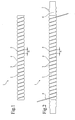
- a nonwoven vascular prosthesis 1 is shown from a Polyurethanansprühvlies in which the vessel wall 2 is formed as a porous Sprühvlies and a helically extending wave-shaped pleating 3 has.
- the prosthesis wall 2 consists of a plurality of polyurethane fibers which form a three-dimensional porous structure and are glued together.
- the porosity corresponds to an air permeability of 30 ml of air per square centimeter per minute at a pressure difference of 1.2 KPas.
- the pleating of the vascular prosthesis has a pitch H of 2.7 mm.
- the curl of pleating 3 is asymmetric.
- the convex, the wave peaks forming bulges 4 have a larger radius than the concave, the troughs forming grooves. 5
- the vascular prosthesis wall has a wall thickness of 0.5 mm.
- the inside diameter of the vascular prosthesis is 5 mm.
- the outer diameter is 6.0 mm in the region of the wave peaks and 5.5 mm in the region of the depressions.
- the vascular prosthesis can be bent around tight radii without collapsing. During radial compression, the restoring force of the pleated vascular prosthesis is significantly greater than with an unpleated vascular prosthesis.
- the prosthesis according to the invention can be produced by using as in FIG. 2 shown a prefabricated porous non woven vascular prosthesis in the form of a cylindrical tube on a rod 6 with a desired pleating corresponding helical corrugation 7 is pushed.
- the prosthesis is briefly heated and snugly fits in by shrinking in the diameter of the bar's waveform, with the bar coil becoming visible on the tube top.
- a thread 8 for example of polyester, is then wound around the prosthesis wall according to the helical shape of the rod, so that the Hose wall is helically pressed into the recesses of the rod helix.
- the tube takes on the waveform of the rod, which remains after cooling.
- the rod can be easily pulled out after removing the thread 8 from the pleated prosthesis.
- a diameter changeable or dismountable core is used.
- cores may be provided in which wedge-shaped or conical inner pieces can be pulled out of the core with a reduction in diameter or the helix is designed to be displaceable on a rod-shaped cylindrical core.
- the prosthesis in pleated form can also be produced directly on the core, for example by dipping or building spraying.
Landscapes
- Health & Medical Sciences (AREA)
- Engineering & Computer Science (AREA)
- Biomedical Technology (AREA)
- Heart & Thoracic Surgery (AREA)
- Pulmonology (AREA)
- Cardiology (AREA)
- Oral & Maxillofacial Surgery (AREA)
- Transplantation (AREA)
- Mechanical Engineering (AREA)
- Gastroenterology & Hepatology (AREA)
- Vascular Medicine (AREA)
- Life Sciences & Earth Sciences (AREA)
- Animal Behavior & Ethology (AREA)
- General Health & Medical Sciences (AREA)
- Public Health (AREA)
- Veterinary Medicine (AREA)
- Prostheses (AREA)
- Materials For Medical Uses (AREA)
Abstract
Description
- Die Erfindung betrifft eine non woven Gefäßprothese.
- Non woven Gefäßprothesen in Form eines porösen Schlauches sind bereits bekannt. Sie können aus expandiertem Polytetrafluorethylen (e-PTFE) hergestellt werden und besitzen je nach Wandstärke eine gute Durchmesserstabilität. Non woven Gefäßprothesen können in geeigneter Weise auch durch Sprühvliesverfahren hergestellt werden, indem eine Lösung eines Polymers in einem leicht flüssigen Lösungsmittel durch Sprühtechnik auf einen Kern aufgesprüht wird. Das Lösungsmittel verflüchtigt sich beim Durchlaufen des Sprühweges, so dass sich auf dem Kern noch klebrige Polymerfasern abscheiden, die sich unter Bildung einer dreidimensionalen Faserstruktur miteinander verkleben. Der Vorteil einer solchen Sprühtechnik ist der, dass sich auch bereits gebogene Gefäßprothesen unter Verwendung eines entsprechend gebogenen Kerns herstellen lassen. Derartige bogenförmige non woven Gefäßprothesen sind beispielsweise in der
DE-A-101 62 821.8 beschrieben. - Es kommt immer wieder vor, dass Gefäßprothesen benötigt werden, bei denen sich gebogene Abschnitte und gerade Abschnitte oder unterschiedlich gebogene Abschnitte abwechseln. Hier ist es schwierig, solche Gefäßprothesen aus vorgefertigten Einzelabschnitten zusammenzusetzen. Es ist deshalb wünschenswert, eine non woven Gefäßprothese herzustellen, die in der gewünschten Weise gebogen werden kann, ohne dass die Gefahr eines Kollabierens besteht.
- Diese Aufgabe wird dadurch gelöst, dass eine non woven Gefäßprothese mit einer Plissierung in der Gefäßwandung bereitgestellt wird.
- Plissierungen sind bei textilen Gefäßprothesen, insbesondere bei gewebten oder gewirkten Gefäßprothesen bekannt. Sie können durch Ausbildung von umlaufenden Querfalten, Kompaktieren der Falten in axialer Richtung und Fixieren der Querfalten geschaffen werden. Die Plissierung bei den textilen Gefäßprothesen besteht aus einer Vielzahl von eng aneinander liegenden ziehharmonikaartigen Falten, die relativ scharfe Kanten aufweisen. In der Regel liegt die Ganghöhe der wendelförmig verlaufenden Plissierung bei textilen Gefäßprothesen unter einem Millimeter.
- Eine solche Ausbildung einer Plissierung ist bei non woven Gefäßprothesen nicht möglich, alleine schon wegen der dreidimensionalen Faserstruktur.
- Gemäß der Erfindung ist die Plissierung vorzugsweise wellenförmig ausgebildet. Übergänge zwischen Wellenbergen und Wellentälern verlaufen zumindest an der äußeren Oberfläche weich. Im Gegensatz zu der Plissierung bei textilen Gefäßprothesen ist bei der Erfindung keine Kompaktierung in Längsrichtung vorgesehen. Dadurch ist die erfindungsgemäße Gefäßprothese in Längsrichtung auch nur geringfügig dehnbar und zwar nur im Rahmen der Elastizität des Wandungsmaterials. Die Dehnbarkeit liegt in der Regel bei den während der Implantation und im Körper auftretenden Längskräften bei maximal 10 %.
- Die erfindungsgemäße Gefäßprothese hat eine sehr gute Durchmesserstabilität und lässt sich um enge Radien biegen, ohne dass die Gefahr eines Kollapses der Prothesenwand zu befürchten ist, im Gegensatz zu den entsprechenden non woven Gefäßprothesen ohne Plissierung.
- Die erfindungsgemäße plissierte Gefäßprothese ist vorzugsweise porös ausgebildet, d.h. sie besitzt eine poröse Gefäßwandung. Diese kann, falls erwünscht, mit einer resorbierbaren Imprägnierung abgedichtet sein. Wie bei den bekannten non woven Gefäßprothesen besteht die erfindungsgemäße Prothese vorzugsweise aus einem Vlies, insbesondere einem Sprühvlies. Polyurethan ist als Wandungsmaterial besonders geeignet. Thermoplastisches Polyurethan, d.h. lineares Polyurethan, insbesondere ein Polyurethan, das in Lösungsmitteln löslich ist, ist bevorzugt. Die als Luftdurchlässigkeit definierte Porosität liegt vorzugsweise bei 1 bis 150 ml Luft pro Quadratzentimeter pro Minute bei einer Druckdifferenz von 1,2 KPas.
- Die Plissierung kann in Form von umlaufenden Rillen vorgesehen sein, eine wendelförmig entlang der Gefäßwandung verlaufende Plissierung ist jedoch bevorzugt. Vertiefungen in der Plissierung, insbesondere Wellentäler sind vorzugsweise als Rillen ausgebildet. Bei einer Ausführungsform der Erfindung werden die Vertiefungen von Einschnürungen gebildet. Im Bereich der Vertiefungen, insbesondere Einschnürungen, kann die Gefäßwandung eine dichtere Struktur aufweisen, insbesondere kompaktiert sein. Eine Verdichtung der Gefäßwandung im Bereich der Vertiefungen im Vergleich zur Wandungsstärke außerhalb der Vertiefungen um 10 bis 60 %, insbesondere 20 bis 50 %, ist bevorzugt. Somit ist das Wandungsmaterial bei einer Ausführungsform der Erfindung im Bereich der Vertiefungen in radialer Richtung kompaktiert und beträgt bevorzugt nur noch 40 bis 90 %, insbesondere 50 bis 80 %, der Wandstärke außerhalb der Verdichtung.
- Der Durchmesser der erfindungsgemäßen Gefäßprothese kann in üblichen Bereichen liegen. Der Innendurchmesser liegt vorzugsweise bei 2 bis 40, insbesondere 4 bis 12, mm. Gerade bei kleineren Innendurchmessern von weniger als 10 mm besitzt die erfindungsgemäße Gefäßprothese besonders günstige Eigenschaften.
- Die Gefäßwandung kann eine Dicke von 0,2 bis 1 mm, insbesondere 0,4 bis 0,6 mm, besitzen. Die Differenz zwischen Wellenberg und Wellental der Plissierung, d.h. die Rillentiefe, liegt vorzugsweise bei 0,2 bis 1 mm, insbesondere 0,4 bis 0,6 mm. Der axiale Abstand von Erhöhung zu Erhöhung, insbesondere die Ganghöhe einer wendelförmigen Plissierung, liegt vorzugsweise im Bereich von 1 bis 5 mm, vorzugsweise 1,5 bis 3,5 mm, insbesondere 2 bis 3 mm. Bei Prothesen mit einem Innendurchmesser von kleiner 10 mm, liegt der axiale Abstand vorzugsweise im größeren Bereich, insbesondere über 2,5 mm, und bei Prothesen mit einem Innendurchmesser von 10 mm und mehr liegt der Abstand vorzugsweise im unteren Bereich, insbesondere unterhalb von 2,5 mm. Eine solche Ausgestaltung erlaubt hervorragende Durchmesserstabilitäten in gebogenem Zustand.
- Die Erfindung betrifft auch ein Verfahren zur Herstellung der erfindungsgemäßen plissierten non woven Gefäßprothese. Zur Herstellung ist es vorgesehen, dass die Gefäßwandung an einem stabförmigen Kern mit einer der Plissierung entsprechenden gewellten Oberfläche abgeformt wird. Vorzugsweise wird ein stabförmiger Kern mit einer wendelförmig umlaufenden Wellung auf seiner Oberfläche eingesetzt, so dass die Gefäßprothese eine entsprechend wendelförmig verlaufende Plissierung aufweist.
- Für die Abformung der Plissierung gibt es verschiedene Möglichkeiten. Bei einer Ausführungsform der Erfindung wird eine vorgefertigte, noch nicht plissierte non woven Gefäßprothese zur Ausbildung der Plissierung auf den stabförmigen Kern aufgeschoben. Die Plissierung wird dann durch querschnittsverjüngende, insbesondere thermische Fixierung ausgebildet. Die vorgefertigte Gefäßprothese kann einen Innendurchmesser aufweisen, der dem Außendurchmesser des stabförmigen Kerns entspricht oder geringfügig größer ist. Es ist auch möglich, eine vorgefertigte schlauchförmige Gefäßprothese unter Durchmesseraufweitung auf den Kern aufzuschieben. Besonders vorteilhaft ist eine vorgefertigte Gefäßprothese, die schrumpffähig ausgebildet ist und auf den gewellten Stab aufgeschrumpft werden kann.
- Die Abformung der Plissierung kann durch bleibende Verjüngung der Gefäßprothese im Bereich der Wellentäler der Plissierung vorgenommen werden. Dies kann durch den zuvor erwähnten Schrumpfeffekt geschehen. Es ist auch möglich, eine Einschnürung der vorgefertigten Gefäßprothese im Bereich der Wellentäler vorzunehmen und diese durch geeignete Maßnahmen zu fixieren. Die Einschnürung kann dadurch vorgenommen werden, dass ein Faden entsprechend der Steigung der Wendel der Plissierung im Bereich der Vertiefungen um die schlauchförmige Gefäßprothese gewickelt und diese dabei in die Vertiefungen des stabförmigen Kerns eingedrückt wird, wonach die Fixierung erfolgt. Es kann auch eine Schrumpfung mit einer mechanischen Einschnürung kombiniert werden. Nach Fixierung der ausgebildeten Plissierung kann der Stab aus der plissierten Gefäßprothese herausgezogen werden.
- Ein Trennen von Stab und plissierter Gefäßprothese kann dadurch erleichtert werden, dass die Oberfläche des Stabes mit einer Gleitschicht versehen wird. Eine solche Gleitschicht kann aus einer gleitenden plastischen Masse bestehen oder in Form einer folienartigen Zwischenschicht ausgebildet sein.
- Bei einer Ausführungsform der Erfindung wird die non woven Gefäßprothese unmittelbar auf dem stabförmigen Kern hergestellt. Dies kann durch unmittelbare Herstellung der plissierten Gefäßwandung auf dem stabförmigen Kern erfolgen. Geeignet ist hierzu wiederum die Sprühtechnik, insbesondere die Sprühvliestechnik.
- Insbesondere für die unmittelbare Herstellung der Gefäßwandung auf dem stabförmigen gewellten Kern eignen sich gemäß einer bevorzugten Ausführungsform solche Kerne, die im Durchmesser verkleinerbar sind oder auch zerlegbare Kerne. So ist es möglich, den Kern mehrteilig auszubilden, beispielsweise kann zur Ausbildung des Kerns ein zylindrischer Stab vorgesehen sein, der mit einer aufschiebbaren und abziehbaren Wendel entsprechender Größe kombiniert ist.
- Weitere Merkmale der Erfindung ergeben sich aus der nachfolgenden Zeichnung in Verbindung mit den Unteransprüchen. Hierbei können die Merkmale jeweils für sich alleine oder in Kombination miteinander vorgesehen sein.
- In der Zeichnungen zeigen
- Figur 1:
- eine Ausführungsform einer erfindungsgemäßen plissierten non woven Gefäßprothese und
- Figur 2:
- ein Herstellungsstadium, bei dem sich die Prothese noch auf einem stabförmigen Kern befindet.
- Bei der Ausführungsform nach
Figur 1 ist eine non woven Gefäßprothese 1 aus einem Polyurethansprühvlies dargestellt, bei der die Gefäßwandung 2 als poröses Sprühvlies ausgebildet ist und eine wendelförmig verlaufende wellenförmige Plissierung 3 aufweist. Die Prothesenwandung 2 besteht aus einer Vielzahl von Polyurethanfasern, die eine dreidimensionale poröse Struktur bilden und miteinander verklebt sind. Die Porosität entspricht einer Luftdurchlässigkeit von 30 ml Luft pro Quadratzentimeter pro Minute bei einer Druckdifferenz von 1,2 KPas. Die Plissierung der Gefäßprothese besitzt eine Ganghöhe H von 2,7 mm. Die Wellung der Plissierung 3 ist asymmetrisch. Die konvexen, die Wellenberge bildenden Wölbungen 4 besitzen einen größeren Radius als die konkaven, die Wellentäler bildenden Rillen 5. - Die Gefäßprothesenwandung hat eine Wandstärke von 0,5 mm. Der lichte Innendurchmesser der Gefäßprothese beträgt 5 mm. Der Außendurchmesser beträgt im Bereich der Wellenberge 6,0 mm und im Bereich der Vertiefungen 5,5 mm.
- Die Gefäßprothese lässt sich um enge Radien biegen, ohne zu kollabieren. Beim radialen Zusammendrücken ist die Rückstellkraft der plissierten Gefäßprothese deutlich größer als bei einer unplissierten Gefäßprothese.
- Hergestellt werden kann die erfindungsgemäße Prothese, indem wie in
Figur 2 gezeigt eine vorgefertigte poröse non woven Gefäßprothese in Form eines zylindrischen Schlauches auf einen Stab 6 mit einer der gewünschten Plissierung entsprechenden wendelförmigen Wellung 7 aufgeschoben wird. Die Prothese wird kurz erwärmt und schmiegt sich durch Schrumpfung im Durchmesser der Wellenform des Stabes etwas an, wobei die Stabwendel an der Schlauchoberseite sichtbar wird. Ein Faden 8, z.B. aus Polyester, wird dann um die Prothesenwandung entsprechend der Wendelform des Stabes gewickelt, so dass die Schlauchwandung wendelförmig in die Vertiefungen der Stabwendel eingedrückt wird. Durch eine thermische Fixierung bei 50 °C nimmt der Schlauch die Wellenform des Stabes an, die nach dem Abkühlen bleibt. Der Stab kann nach dem Entfernen des Fadens 8 aus der plissierten Prothese mühelos herausgezogen werden. - Bei einer anderen Ausführungsform zur Herstellung der erfindungsgemäßen Prothese wird ein im Durchmesser veränderbarer oder zerlegbarer Kern verwendet. Bei dieser Ausführungsform können Kerne vorgesehen sein, bei denen keilförmige oder konische Innenstücke aus dem Kern unter Durchmesserverringerung herausziehbar sind oder die Wendel auf einem stabförmigen zylindrischen Kern verschiebbar ausgebildet ist. Insbesondere bei Verwendung solcher Kerne kann die Prothese in plissierter Form auch unmittelbar auf dem Kern, beispielsweise durch Tauchen oder aufbauendes Sprühen, hergestellt werden.
Claims (21)
- Non woven Gefäßprothese (1) mit einer Plissierung (3) in der Gefäßwandung (2).
- Non woven Gefäßprothese (1), dadurch gekennzeichnet, dass die Plissierung (3) wellenförmig ausgebildet ist.
- Non woven Gefäßprothese nach einem der Ansprüche 1 oder 2, dadurch gekennzeichnet, dass die Gefäßwandung (2) porös ist und gegebenenfalls mit einer resorbierbaren Imprägnierung abgedichtet ist.
- Non woven Gefäßprothese nach einem der vorhergehenden Ansprüche, dadurch gekennzeichnet, dass die Gefäßwandung (2) von einem Vlies, insbesondere einem Sprühvlies gebildet wird.
- Non woven Gefäßprothese nach einem der Ansprüche 1 bis 4, dadurch gekennzeichnet, dass die Gefäßwandung (2) aus Polyurethan gebildet ist.
- Non woven Gefäßprothese nach Anspruch 5, dadurch gekennzeichnet, dass das Polyurethan ein thermoplastisches Polyurethan, insbesondere ein in Lösungsmittel lösliches Polyurethan ist.
- Non woven Gefäßprothese nach einem der vorhergehenden Ansprüche, dadurch gekennzeichnet, dass die Plissierung (3) Rillen (5) aufweist, die vorzugsweise wendelförmig entlang der Gefäßwandung (2) verlaufen.
- Non woven Gefäßprothese nach einem der vorhergehenden Ansprüche, dadurch gekennzeichnet, dass Vertiefungen, insbesondere Rillen (5), der Plissierung (3) von Einschnürungen gebildet werden.
- Non woven Gefäßprothese nach Anspruch 8, dadurch gekennzeichnet, dass die Gefäßwandung (2) im Bereich der Vertiefungen (5), insbesondere durch Einschnürungen, verdichtet ist.
- Non woven Gefäßprothesen nach einem der vorhergehenden Ansprüche, dadurch gekennzeichnet, dass der Innendurchmesser der Prothese 2 bis 40 mm, insbesondere 4 bis 12 mm, beträgt.
- Non woven Gefäßprothese nach einem der vorhergehenden Ansprüche, dadurch gekennzeichnet, dass die Wandstärke der Gefäßwandung (2) 0,2 bis 1 mm, insbesondere 0,4 bis 0,6 mm, beträgt.
- Non woven Gefäßprothese nach einem der vorhergehenden Ansprüche, dadurch gekennzeichnet, dass die Plissierung (3) eine Rillentiefe von 0,2 bis 1 mm, insbesondere 0,4 bis 0,6 mm, besitzt.
- Verfahren zur Herstellung der plissierten non woven Gefäßprothese nach einem der vorhergehenden Ansprüche dadurch gekennzeichnet, dass die Gefäßwandung an einem stabförmigen Kern mit einer der Plissierung entsprechenden gewellten Oberfläche abgeformt wird.
- Verfahren nach Anspruch 15, dadurch gekennzeichnet, dass ein stabförmiger Kern mit einer wendelförmig umlaufenden Wellung auf seiner Oberfläche eingesetzt wird.
- Verfahren nach Anspruch 13 oder 14, dadurch gekennzeichnet, dass eine vorgefertigte, noch nicht plissierte non woven Gefäßprothese zur Ausbildung der Plissierung auf den stabförmigen Kern aufgeschoben wird und die Plissierung durch querschnittsverjüngende, insbesondere thermische Fixierung ausgebildet wird.
- Verfahren nach einem der Ansprüche 13 bis 15, dadurch gekennzeichnet, dass die vorgefertigte Gefäßprothese auf dem stabförmigen Kern entsprechend der wellenförmigen Oberfläche in den Wellentälern eingeschnürt wird und die Einschnürungen fixiert werden.
- Verfahren nach einem der Ansprüche 13 bis 16, dadurch gekennzeichnet, dass eine im Querschnitt reversibel vorgedehnte vorgefertigte Gefäßprothese auf den stabförmigen Kern aufgeschoben und auf diesen aufgeschrumpft wird.
- Verfahren nach einem der Ansprüche 13 bis 17, dadurch gekennzeichnet, dass auf den stabförmigen Kern, insbesondere zwischen den stabförmigen Kern und die vorgefertigte Gefäßprothese, eine gleitfähige Zwischenschicht, insbesondere eine Folie aufgebracht wird.
- Verfahren nach einem der Ansprüche 13, 14 oder 18, dadurch gekennzeichnet, dass die Prothese mit Plissierung durch Aufsprühen einer Lösung von Polyurethan auf den stabförmigen Kern als Sprühvlies mit gewellter Oberfläche ausgebildet wird.
- Verfahren nach einem der Ansprüche 13 bis 19 dadurch gekennzeichnet, dass ein im Querschnitt verringerbarer Kern mit gewellter Oberfläche eingesetzt wird und der Querschnitt des Kerns zum erleichterten Abziehen der plissierten Gefäßprothese verringert wird.
- Verfahren nach einem der Ansprüche 13 bis 20, dadurch gekennzeichnet, dass die gewellte Oberfläche des Kerns von einer auf einen Stab gewickelten, vorzugsweise in Längsrichtung abziehbaren, Wendel gebildet wird.
Applications Claiming Priority (1)
| Application Number | Priority Date | Filing Date | Title |
|---|---|---|---|
| DE102007008185A DE102007008185A1 (de) | 2007-02-13 | 2007-02-13 | Non woven Gefäßprothese und Verfahren zu ihrer Herstellung |
Publications (3)
| Publication Number | Publication Date |
|---|---|
| EP1958590A2 true EP1958590A2 (de) | 2008-08-20 |
| EP1958590A3 EP1958590A3 (de) | 2009-08-26 |
| EP1958590B1 EP1958590B1 (de) | 2015-04-29 |
Family
ID=39332078
Family Applications (1)
| Application Number | Title | Priority Date | Filing Date |
|---|---|---|---|
| EP08002588.5A Not-in-force EP1958590B1 (de) | 2007-02-13 | 2008-02-13 | Nicht gewebte Gefässprothese und Verfahren zu Ihrer Herstellung |
Country Status (3)
| Country | Link |
|---|---|
| US (1) | US20080228262A1 (de) |
| EP (1) | EP1958590B1 (de) |
| DE (1) | DE102007008185A1 (de) |
Families Citing this family (11)
| Publication number | Priority date | Publication date | Assignee | Title |
|---|---|---|---|---|
| US7879085B2 (en) * | 2002-09-06 | 2011-02-01 | Boston Scientific Scimed, Inc. | ePTFE crimped graft |
| US8435283B2 (en) * | 2007-06-13 | 2013-05-07 | Boston Scientific Scimed, Inc. | Anti-migration features and geometry for a shape memory polymer stent |
| EP2349080B1 (de) * | 2008-10-22 | 2016-04-13 | Boston Scientific Scimed, Inc. | Röhrenförmiger stent mit formgedächtnis und kerben |
| US8641753B2 (en) | 2009-01-31 | 2014-02-04 | Cook Medical Technologies Llc | Preform for and an endoluminal prosthesis |
| EP2519189B1 (de) | 2009-12-28 | 2014-05-07 | Cook Medical Technologies LLC | Endoluminale vorrichtung mit knickfesten bereichen |
| AU2012203620B9 (en) | 2011-06-24 | 2014-10-02 | Cook Medical Technologies Llc | Helical Stent |
| EP4302726A3 (de) | 2014-10-09 | 2024-03-27 | Boston Scientific Scimed, Inc. | Dorn und verfahren zur herstellung einer expandierbaren stentstruktur |
| CN118634073A (zh) | 2019-01-07 | 2024-09-13 | 波士顿科学国际有限公司 | 具有抗迁移功能的支架 |
| CA3195219A1 (en) | 2020-09-29 | 2022-04-07 | Boston Scientific Scimed, Inc. | Stent with anti-migration features |
| AU2021390484B2 (en) | 2020-12-02 | 2024-12-12 | Boston Scientific Scimed, Inc. | Stent with improved deployment characteristics |
| CN117656439A (zh) * | 2023-12-18 | 2024-03-08 | 武汉纺织大学 | 用于制备螺纹形人造血管的定型方法及装置 |
Citations (2)
| Publication number | Priority date | Publication date | Assignee | Title |
|---|---|---|---|---|
| WO2000038591A2 (en) | 1998-12-29 | 2000-07-06 | Tayside University Hospitals Nhs Trust | Blood-flow tubing |
| DE10162821A1 (de) | 2001-12-14 | 2003-06-26 | Hans-Hinrich Sievers | Gefässprothese, insbesondere zum Ersatz von herznahen Bereichen der Aorta |
Family Cites Families (13)
| Publication number | Priority date | Publication date | Assignee | Title |
|---|---|---|---|---|
| US2446281A (en) * | 1944-05-11 | 1948-08-03 | Us Rubber Co | Corrugated tube manufacture |
| DE1209279B (de) * | 1958-07-31 | 1966-01-20 | Us Catheter & Instr Corp | Verfahren zur Herstellung von Wellungen auf einem glatten biegsamen rohrfoermigen Teil, insbesondere auf kuenstlichen Blutgefaessen |
| FR1538078A (fr) * | 1967-08-22 | 1968-08-30 | Braun Internat Gmbh B | Procédé pour la fabrication de prothèses tubulaires et lisses en tissu biologique |
| US4164045A (en) * | 1977-08-03 | 1979-08-14 | Carbomedics, Inc. | Artificial vascular and patch grafts |
| DE4430485C1 (de) * | 1994-08-27 | 1996-03-07 | Braun B Surgical Gmbh | Textile Gefäßprothese, Verfahren zu ihrer Herstellung und Werkzeug zu ihrer Herstellung |
| US6540780B1 (en) * | 1998-11-23 | 2003-04-01 | Medtronic, Inc. | Porous synthetic vascular grafts with oriented ingrowth channels |
| US7510571B2 (en) * | 2001-06-11 | 2009-03-31 | Boston Scientific, Scimed, Inc. | Pleated composite ePTFE/textile hybrid covering |
| GB0306176D0 (en) * | 2003-03-18 | 2003-04-23 | Imp College Innovations Ltd | Tubing |
| DE20306639U1 (de) * | 2003-04-28 | 2003-06-26 | GfE Medizintechnik GmbH, 90431 Nürnberg | Gefäßprothese |
| WO2004100827A2 (en) * | 2003-05-07 | 2004-11-25 | Advanced Bio Prosthetic Surfaces, Ltd. | Metallic implantable grafts and method of making same |
| US20050038503A1 (en) * | 2003-05-29 | 2005-02-17 | Secor Medical, Llc | Filament based prosthesis |
| US7575591B2 (en) * | 2003-12-01 | 2009-08-18 | Cordis Corporation | Prosthesis graft with Z pleating |
| CN101060817B (zh) * | 2004-11-19 | 2011-08-03 | 帝人株式会社 | 圆筒体的制造方法 |
-
2007
- 2007-02-13 DE DE102007008185A patent/DE102007008185A1/de not_active Ceased
-
2008
- 2008-02-12 US US12/068,848 patent/US20080228262A1/en not_active Abandoned
- 2008-02-13 EP EP08002588.5A patent/EP1958590B1/de not_active Not-in-force
Patent Citations (2)
| Publication number | Priority date | Publication date | Assignee | Title |
|---|---|---|---|---|
| WO2000038591A2 (en) | 1998-12-29 | 2000-07-06 | Tayside University Hospitals Nhs Trust | Blood-flow tubing |
| DE10162821A1 (de) | 2001-12-14 | 2003-06-26 | Hans-Hinrich Sievers | Gefässprothese, insbesondere zum Ersatz von herznahen Bereichen der Aorta |
Also Published As
| Publication number | Publication date |
|---|---|
| EP1958590A3 (de) | 2009-08-26 |
| DE102007008185A1 (de) | 2008-08-14 |
| EP1958590B1 (de) | 2015-04-29 |
| US20080228262A1 (en) | 2008-09-18 |
Similar Documents
| Publication | Publication Date | Title |
|---|---|---|
| EP1958590B1 (de) | Nicht gewebte Gefässprothese und Verfahren zu Ihrer Herstellung | |
| DE69829430T2 (de) | Okklusionsvorrichtung | |
| DE4430485C1 (de) | Textile Gefäßprothese, Verfahren zu ihrer Herstellung und Werkzeug zu ihrer Herstellung | |
| EP2628455B1 (de) | Medizinische Vorrichtung mit einer Gitterstruktur und Behandlungssystem mit einer derartigen medizinischen Vorrichtung | |
| DE4446036C2 (de) | Platzhalter zum Anordnen in einer Körperröhre | |
| DE3019996C2 (de) | ||
| DE69712606T2 (de) | Präservative | |
| DE2409178C2 (de) | Verfahren zum Herstellen von Rohren aus Polytetrafluoräthylen | |
| EP0734698A2 (de) | Stent zur transluminalen Implantation in Hohlorgane | |
| DE10223399A1 (de) | Gefäßstütze (STENT) | |
| DE102008048416A1 (de) | Medizinische Vorrichtung und Verfahren zum Herstellen einer derartigen Vorrichtung | |
| WO2009115403A1 (de) | Tracheostomiekanüle aus mindestens zwei verschiedenen kunststoffen | |
| DE102014014015A1 (de) | Dehnbare Einführschleuse | |
| WO2016075030A1 (de) | Wellrohranordnung zur aufnahme von leitungen und verfahren zur herstellung einer solchen wellrohranordnung | |
| EP2667831B1 (de) | Medizinische vorrichtung mit einer gitterstruktur und behandlungssystem mit einer derartigen vorrichtung | |
| WO2018073142A1 (de) | Filter und verfahren zur herstellung eines filters | |
| DE8812719U1 (de) | Vorrichtung zum Beheben von Stenosen | |
| EP2947364B1 (de) | Schlauchverbindungs-vorrichtung und massage-toy mit einer solchen schlauchverbindungs-vorrichtung | |
| WO2018091169A1 (de) | Verfahren und vorrichtung zur herstellung eines selbstführenden geschlossenen endloszahnriemens | |
| DE102011011150A1 (de) | Medizinische Vorrichtung mit einem expandierbaren Gittergeflecht | |
| DE102008027102A1 (de) | Doppelwand-Wellrohr und Formbacken für eine Vorrichtung zur Herstellung eines derartigen Doppelwand-Wellrohres | |
| DE102015122678A1 (de) | Medizinisches Implantat | |
| DE102016008111A1 (de) | Verfahren zur Herstellung eines Schlauchanschlusses und Schlauchanschluss | |
| DE102016013090B4 (de) | Filterkerze, Verfahren zu deren Herstellung und mehrteiliges Spritzgießwerkzeug zur Durchführung des Verfahrens | |
| DE19513906C2 (de) | Keramisches Hitzeschild |
Legal Events
| Date | Code | Title | Description |
|---|---|---|---|
| PUAI | Public reference made under article 153(3) epc to a published international application that has entered the european phase |
Free format text: ORIGINAL CODE: 0009012 |
|
| AK | Designated contracting states |
Kind code of ref document: A2 Designated state(s): AT BE BG CH CY CZ DE DK EE ES FI FR GB GR HR HU IE IS IT LI LT LU LV MC MT NL NO PL PT RO SE SI SK TR |
|
| AX | Request for extension of the european patent |
Extension state: AL BA MK RS |
|
| RAP1 | Party data changed (applicant data changed or rights of an application transferred) |
Owner name: AESCULAP AG |
|
| PUAL | Search report despatched |
Free format text: ORIGINAL CODE: 0009013 |
|
| AK | Designated contracting states |
Kind code of ref document: A3 Designated state(s): AT BE BG CH CY CZ DE DK EE ES FI FR GB GR HR HU IE IS IT LI LT LU LV MC MT NL NO PL PT RO SE SI SK TR |
|
| AX | Request for extension of the european patent |
Extension state: AL BA MK RS |
|
| 17P | Request for examination filed |
Effective date: 20100202 |
|
| 17Q | First examination report despatched |
Effective date: 20100301 |
|
| AKX | Designation fees paid |
Designated state(s): AT BE BG CH CY CZ DE DK EE ES FI FR GB GR HR HU IE IS IT LI LT LU LV MC MT NL NO PL PT RO SE SI SK TR |
|
| GRAP | Despatch of communication of intention to grant a patent |
Free format text: ORIGINAL CODE: EPIDOSNIGR1 |
|
| INTG | Intention to grant announced |
Effective date: 20141119 |
|
| RIN1 | Information on inventor provided before grant (corrected) |
Inventor name: PROBST, DIETMAR Inventor name: GOLDMAN, HELMUT Inventor name: LANGANKE, DENNIS |
|
| GRAS | Grant fee paid |
Free format text: ORIGINAL CODE: EPIDOSNIGR3 |
|
| GRAA | (expected) grant |
Free format text: ORIGINAL CODE: 0009210 |
|
| AK | Designated contracting states |
Kind code of ref document: B1 Designated state(s): AT BE BG CH CY CZ DE DK EE ES FI FR GB GR HR HU IE IS IT LI LT LU LV MC MT NL NO PL PT RO SE SI SK TR |
|
| REG | Reference to a national code |
Ref country code: GB Ref legal event code: FG4D Free format text: NOT ENGLISH |
|
| REG | Reference to a national code |
Ref country code: CH Ref legal event code: EP |
|
| REG | Reference to a national code |
Ref country code: AT Ref legal event code: REF Ref document number: 724016 Country of ref document: AT Kind code of ref document: T Effective date: 20150515 |
|
| REG | Reference to a national code |
Ref country code: IE Ref legal event code: FG4D Free format text: LANGUAGE OF EP DOCUMENT: GERMAN |
|
| REG | Reference to a national code |
Ref country code: DE Ref legal event code: R096 Ref document number: 502008012922 Country of ref document: DE Effective date: 20150603 |
|
| REG | Reference to a national code |
Ref country code: NL Ref legal event code: VDEP Effective date: 20150429 |
|
| REG | Reference to a national code |
Ref country code: LT Ref legal event code: MG4D |
|
| PG25 | Lapsed in a contracting state [announced via postgrant information from national office to epo] |
Ref country code: NL Free format text: LAPSE BECAUSE OF FAILURE TO SUBMIT A TRANSLATION OF THE DESCRIPTION OR TO PAY THE FEE WITHIN THE PRESCRIBED TIME-LIMIT Effective date: 20150429 |
|
| PG25 | Lapsed in a contracting state [announced via postgrant information from national office to epo] |
Ref country code: ES Free format text: LAPSE BECAUSE OF FAILURE TO SUBMIT A TRANSLATION OF THE DESCRIPTION OR TO PAY THE FEE WITHIN THE PRESCRIBED TIME-LIMIT Effective date: 20150429 Ref country code: LT Free format text: LAPSE BECAUSE OF FAILURE TO SUBMIT A TRANSLATION OF THE DESCRIPTION OR TO PAY THE FEE WITHIN THE PRESCRIBED TIME-LIMIT Effective date: 20150429 Ref country code: FI Free format text: LAPSE BECAUSE OF FAILURE TO SUBMIT A TRANSLATION OF THE DESCRIPTION OR TO PAY THE FEE WITHIN THE PRESCRIBED TIME-LIMIT Effective date: 20150429 Ref country code: NO Free format text: LAPSE BECAUSE OF FAILURE TO SUBMIT A TRANSLATION OF THE DESCRIPTION OR TO PAY THE FEE WITHIN THE PRESCRIBED TIME-LIMIT Effective date: 20150729 Ref country code: PT Free format text: LAPSE BECAUSE OF FAILURE TO SUBMIT A TRANSLATION OF THE DESCRIPTION OR TO PAY THE FEE WITHIN THE PRESCRIBED TIME-LIMIT Effective date: 20150831 Ref country code: HR Free format text: LAPSE BECAUSE OF FAILURE TO SUBMIT A TRANSLATION OF THE DESCRIPTION OR TO PAY THE FEE WITHIN THE PRESCRIBED TIME-LIMIT Effective date: 20150429 |
|
| PG25 | Lapsed in a contracting state [announced via postgrant information from national office to epo] |
Ref country code: LV Free format text: LAPSE BECAUSE OF FAILURE TO SUBMIT A TRANSLATION OF THE DESCRIPTION OR TO PAY THE FEE WITHIN THE PRESCRIBED TIME-LIMIT Effective date: 20150429 Ref country code: GR Free format text: LAPSE BECAUSE OF FAILURE TO SUBMIT A TRANSLATION OF THE DESCRIPTION OR TO PAY THE FEE WITHIN THE PRESCRIBED TIME-LIMIT Effective date: 20150730 Ref country code: IS Free format text: LAPSE BECAUSE OF FAILURE TO SUBMIT A TRANSLATION OF THE DESCRIPTION OR TO PAY THE FEE WITHIN THE PRESCRIBED TIME-LIMIT Effective date: 20150829 |
|
| PG25 | Lapsed in a contracting state [announced via postgrant information from national office to epo] |
Ref country code: DK Free format text: LAPSE BECAUSE OF FAILURE TO SUBMIT A TRANSLATION OF THE DESCRIPTION OR TO PAY THE FEE WITHIN THE PRESCRIBED TIME-LIMIT Effective date: 20150429 Ref country code: EE Free format text: LAPSE BECAUSE OF FAILURE TO SUBMIT A TRANSLATION OF THE DESCRIPTION OR TO PAY THE FEE WITHIN THE PRESCRIBED TIME-LIMIT Effective date: 20150429 |
|
| REG | Reference to a national code |
Ref country code: DE Ref legal event code: R097 Ref document number: 502008012922 Country of ref document: DE |
|
| PG25 | Lapsed in a contracting state [announced via postgrant information from national office to epo] |
Ref country code: RO Free format text: LAPSE BECAUSE OF NON-PAYMENT OF DUE FEES Effective date: 20150429 Ref country code: SK Free format text: LAPSE BECAUSE OF FAILURE TO SUBMIT A TRANSLATION OF THE DESCRIPTION OR TO PAY THE FEE WITHIN THE PRESCRIBED TIME-LIMIT Effective date: 20150429 Ref country code: CZ Free format text: LAPSE BECAUSE OF FAILURE TO SUBMIT A TRANSLATION OF THE DESCRIPTION OR TO PAY THE FEE WITHIN THE PRESCRIBED TIME-LIMIT Effective date: 20150429 Ref country code: PL Free format text: LAPSE BECAUSE OF FAILURE TO SUBMIT A TRANSLATION OF THE DESCRIPTION OR TO PAY THE FEE WITHIN THE PRESCRIBED TIME-LIMIT Effective date: 20150429 |
|
| PLBE | No opposition filed within time limit |
Free format text: ORIGINAL CODE: 0009261 |
|
| STAA | Information on the status of an ep patent application or granted ep patent |
Free format text: STATUS: NO OPPOSITION FILED WITHIN TIME LIMIT |
|
| 26N | No opposition filed |
Effective date: 20160201 |
|
| PG25 | Lapsed in a contracting state [announced via postgrant information from national office to epo] |
Ref country code: IT Free format text: LAPSE BECAUSE OF FAILURE TO SUBMIT A TRANSLATION OF THE DESCRIPTION OR TO PAY THE FEE WITHIN THE PRESCRIBED TIME-LIMIT Effective date: 20150429 |
|
| PG25 | Lapsed in a contracting state [announced via postgrant information from national office to epo] |
Ref country code: BE Free format text: LAPSE BECAUSE OF NON-PAYMENT OF DUE FEES Effective date: 20160229 Ref country code: SI Free format text: LAPSE BECAUSE OF FAILURE TO SUBMIT A TRANSLATION OF THE DESCRIPTION OR TO PAY THE FEE WITHIN THE PRESCRIBED TIME-LIMIT Effective date: 20150429 |
|
| PG25 | Lapsed in a contracting state [announced via postgrant information from national office to epo] |
Ref country code: LU Free format text: LAPSE BECAUSE OF FAILURE TO SUBMIT A TRANSLATION OF THE DESCRIPTION OR TO PAY THE FEE WITHIN THE PRESCRIBED TIME-LIMIT Effective date: 20160213 Ref country code: MC Free format text: LAPSE BECAUSE OF FAILURE TO SUBMIT A TRANSLATION OF THE DESCRIPTION OR TO PAY THE FEE WITHIN THE PRESCRIBED TIME-LIMIT Effective date: 20150429 |
|
| REG | Reference to a national code |
Ref country code: CH Ref legal event code: PL |
|
| GBPC | Gb: european patent ceased through non-payment of renewal fee |
Effective date: 20160213 |
|
| PG25 | Lapsed in a contracting state [announced via postgrant information from national office to epo] |
Ref country code: CH Free format text: LAPSE BECAUSE OF NON-PAYMENT OF DUE FEES Effective date: 20160229 Ref country code: LI Free format text: LAPSE BECAUSE OF NON-PAYMENT OF DUE FEES Effective date: 20160229 |
|
| REG | Reference to a national code |
Ref country code: FR Ref legal event code: ST Effective date: 20161028 |
|
| REG | Reference to a national code |
Ref country code: IE Ref legal event code: MM4A |
|
| PG25 | Lapsed in a contracting state [announced via postgrant information from national office to epo] |
Ref country code: IE Free format text: LAPSE BECAUSE OF NON-PAYMENT OF DUE FEES Effective date: 20160213 Ref country code: GB Free format text: LAPSE BECAUSE OF NON-PAYMENT OF DUE FEES Effective date: 20160213 Ref country code: FR Free format text: LAPSE BECAUSE OF NON-PAYMENT OF DUE FEES Effective date: 20160229 |
|
| REG | Reference to a national code |
Ref country code: AT Ref legal event code: MM01 Ref document number: 724016 Country of ref document: AT Kind code of ref document: T Effective date: 20160213 |
|
| PG25 | Lapsed in a contracting state [announced via postgrant information from national office to epo] |
Ref country code: AT Free format text: LAPSE BECAUSE OF NON-PAYMENT OF DUE FEES Effective date: 20160213 |
|
| PG25 | Lapsed in a contracting state [announced via postgrant information from national office to epo] |
Ref country code: SE Free format text: LAPSE BECAUSE OF FAILURE TO SUBMIT A TRANSLATION OF THE DESCRIPTION OR TO PAY THE FEE WITHIN THE PRESCRIBED TIME-LIMIT Effective date: 20150429 |
|
| PG25 | Lapsed in a contracting state [announced via postgrant information from national office to epo] |
Ref country code: MT Free format text: LAPSE BECAUSE OF FAILURE TO SUBMIT A TRANSLATION OF THE DESCRIPTION OR TO PAY THE FEE WITHIN THE PRESCRIBED TIME-LIMIT Effective date: 20150429 |
|
| PG25 | Lapsed in a contracting state [announced via postgrant information from national office to epo] |
Ref country code: HU Free format text: LAPSE BECAUSE OF FAILURE TO SUBMIT A TRANSLATION OF THE DESCRIPTION OR TO PAY THE FEE WITHIN THE PRESCRIBED TIME-LIMIT; INVALID AB INITIO Effective date: 20080213 Ref country code: CY Free format text: LAPSE BECAUSE OF FAILURE TO SUBMIT A TRANSLATION OF THE DESCRIPTION OR TO PAY THE FEE WITHIN THE PRESCRIBED TIME-LIMIT Effective date: 20150429 |
|
| PG25 | Lapsed in a contracting state [announced via postgrant information from national office to epo] |
Ref country code: TR Free format text: LAPSE BECAUSE OF FAILURE TO SUBMIT A TRANSLATION OF THE DESCRIPTION OR TO PAY THE FEE WITHIN THE PRESCRIBED TIME-LIMIT Effective date: 20150429 |
|
| PG25 | Lapsed in a contracting state [announced via postgrant information from national office to epo] |
Ref country code: BG Free format text: LAPSE BECAUSE OF FAILURE TO SUBMIT A TRANSLATION OF THE DESCRIPTION OR TO PAY THE FEE WITHIN THE PRESCRIBED TIME-LIMIT Effective date: 20150429 |
|
| PGFP | Annual fee paid to national office [announced via postgrant information from national office to epo] |
Ref country code: DE Payment date: 20210223 Year of fee payment: 14 |
|
| REG | Reference to a national code |
Ref country code: DE Ref legal event code: R119 Ref document number: 502008012922 Country of ref document: DE |
|
| PG25 | Lapsed in a contracting state [announced via postgrant information from national office to epo] |
Ref country code: DE Free format text: LAPSE BECAUSE OF NON-PAYMENT OF DUE FEES Effective date: 20220901 |