EP1956148A1 - Working machine - Google Patents
Working machine Download PDFInfo
- Publication number
- EP1956148A1 EP1956148A1 EP06798140A EP06798140A EP1956148A1 EP 1956148 A1 EP1956148 A1 EP 1956148A1 EP 06798140 A EP06798140 A EP 06798140A EP 06798140 A EP06798140 A EP 06798140A EP 1956148 A1 EP1956148 A1 EP 1956148A1
- Authority
- EP
- European Patent Office
- Prior art keywords
- operated
- operating
- foot
- traveling
- travel
- Prior art date
- Legal status (The legal status is an assumption and is not a legal conclusion. Google has not performed a legal analysis and makes no representation as to the accuracy of the status listed.)
- Withdrawn
Links
- 238000000034 method Methods 0.000 description 28
- 230000000994 depressogenic effect Effects 0.000 description 11
- 230000007935 neutral effect Effects 0.000 description 10
- 239000003921 oil Substances 0.000 description 3
- 230000000694 effects Effects 0.000 description 2
- 238000010586 diagram Methods 0.000 description 1
- 239000010720 hydraulic oil Substances 0.000 description 1
- 238000009434 installation Methods 0.000 description 1
Images


Classifications
-
- E—FIXED CONSTRUCTIONS
- E02—HYDRAULIC ENGINEERING; FOUNDATIONS; SOIL SHIFTING
- E02F—DREDGING; SOIL-SHIFTING
- E02F9/00—Component parts of dredgers or soil-shifting machines, not restricted to one of the kinds covered by groups E02F3/00 - E02F7/00
- E02F9/20—Drives; Control devices
- E02F9/2004—Control mechanisms, e.g. control levers
-
- E—FIXED CONSTRUCTIONS
- E02—HYDRAULIC ENGINEERING; FOUNDATIONS; SOIL SHIFTING
- E02F—DREDGING; SOIL-SHIFTING
- E02F9/00—Component parts of dredgers or soil-shifting machines, not restricted to one of the kinds covered by groups E02F3/00 - E02F7/00
- E02F9/20—Drives; Control devices
- E02F9/2025—Particular purposes of control systems not otherwise provided for
-
- Y—GENERAL TAGGING OF NEW TECHNOLOGICAL DEVELOPMENTS; GENERAL TAGGING OF CROSS-SECTIONAL TECHNOLOGIES SPANNING OVER SEVERAL SECTIONS OF THE IPC; TECHNICAL SUBJECTS COVERED BY FORMER USPC CROSS-REFERENCE ART COLLECTIONS [XRACs] AND DIGESTS
- Y10—TECHNICAL SUBJECTS COVERED BY FORMER USPC
- Y10T—TECHNICAL SUBJECTS COVERED BY FORMER US CLASSIFICATION
- Y10T74/00—Machine element or mechanism
- Y10T74/20—Control lever and linkage systems
- Y10T74/20012—Multiple controlled elements
-
- Y—GENERAL TAGGING OF NEW TECHNOLOGICAL DEVELOPMENTS; GENERAL TAGGING OF CROSS-SECTIONAL TECHNOLOGIES SPANNING OVER SEVERAL SECTIONS OF THE IPC; TECHNICAL SUBJECTS COVERED BY FORMER USPC CROSS-REFERENCE ART COLLECTIONS [XRACs] AND DIGESTS
- Y10—TECHNICAL SUBJECTS COVERED BY FORMER USPC
- Y10T—TECHNICAL SUBJECTS COVERED BY FORMER US CLASSIFICATION
- Y10T74/00—Machine element or mechanism
- Y10T74/20—Control lever and linkage systems
- Y10T74/20528—Foot operated
-
- Y—GENERAL TAGGING OF NEW TECHNOLOGICAL DEVELOPMENTS; GENERAL TAGGING OF CROSS-SECTIONAL TECHNOLOGIES SPANNING OVER SEVERAL SECTIONS OF THE IPC; TECHNICAL SUBJECTS COVERED BY FORMER USPC CROSS-REFERENCE ART COLLECTIONS [XRACs] AND DIGESTS
- Y10—TECHNICAL SUBJECTS COVERED BY FORMER USPC
- Y10T—TECHNICAL SUBJECTS COVERED BY FORMER US CLASSIFICATION
- Y10T74/00—Machine element or mechanism
- Y10T74/20—Control lever and linkage systems
- Y10T74/20528—Foot operated
- Y10T74/2054—Signal
Definitions
- the present invention relates to a work machine provided with a traveling devices and a work device.
- a hydraulic shovel 1 is a work machine provided with a lower structure, an upper swing body 3, a cab 4, and a work device 5.
- the lower structure has right and left traveling devices 2 adapted to be respectively driven by right and left travel motors 2m.
- the upper swing body 3 is adapted to be rotated on the lower structure by a swing motor 3m.
- the cab 4 and the work device 5 are mounted on the upper swing body 3.
- the work device 5 comprises a boom 6 adapted to be vertically pivoted by boom cylinders 6c, a stick 7 to be pivoted by a stick cylinder 7c, and a bucket 8 to be pivoted by a bucket cylinder 8c, wherein the base end of the boom 6 is supported at the upper swing body 3 by a shaft; the stick 7 is supported at the distal end of the boom 6 by a shaft; and the bucket 8 is supported at the distal end of the stick 7 by a shaft.
- traveling pedals and travel levers for operating the right and left traveling devices 2 of the lower structure are disposed on the floor in front of the operating seat.
- traveling pedals with the feet is sufficient for broad travel operation but inadequate to perform fine operation. Therefore, when performing fine operation with a travel lever, it is necessary for the operator to remove a hand from one of the operating levers (work device/swing operating levers) that are disposed at the right and left sides of the operating seat respectively to rotate the upper swing body 3 or the work device 5, and reach for the travel lever, which is disposed in front of the operator.
- the operating levers work device/swing operating levers
- a structure that includes travel levers disposed in front of the operating seat may cause the travel levers to obstruct the operator from entering or exiting the cab 4, or it compels the operator to change his position or shift his hand when operating a travel lever.
- Some examples of conventionally known structures to solve the above problems include providing a travel control lever in the proximity of a work device/swing operating lever disposed at a side of the operating seat (e. g. See Patent Documents 1, 2, 3, and 4).
- any one of the structures that are offered in the Patent Documents mentioned above and include a switchover device provided separately from the operating levers the operator has to remove his hand from an operating lever in order to operate the switchover device, which is nearly as inconvenient as switching one's hand from one lever to another. Even if the switchover device is attached to an operating lever, it is difficult for the operator to ascertain whether switchover has taken place, and the operator has to think about which device the operating lever has engaged for operation at the moment.
- a work machine having travel levers disposed on the floor in front of the operating seat not only makes it difficult for the operator to enter or exist the machine but also compels the operator to change his position or shift his hand when operating a travel lever. Even if a switchover device is provided separately from the operating levers, the operator has to remove his hand from an operating lever in order to operate the switchover device.
- an object of the invention is to provide a work machine equipped with a switchover means enabling selective operation of a traveling device and a work device by means of a common operating lever, wherein switchover can easily be performed and also easily recognized.
- the present invention according to Claim 1 relates to a work machine having a traveling device and a work device, wherein the work machine includes an operating seat; an operating lever disposed at a side of the operating seat and able to operate the traveling device and the work device; a foot-operated switchover means disposed in the proximity of and operable with a foot of an operator seated at the operating seat; and a controller adapted to control the traveling device through the operating lever while the foot-operated switchover means is being operated with the foot, and control the work device through the operating lever while the foot-operated switchover means is not being operated.
- the present invention according to Claim 2 relates to the work machine of Claim 1, wherein the work machine further includes a traveling alarm adapted to be activated when the foot-operated switchover means is operated with the foot.
- the present invention according to Claim 3 relates to the work machine of Claim 1 or Claim 2, wherein the work machine further includes a traveling pedal adapted to be operated with a foot of the operator seated at the operating seat; and a warning alarm adapted to be activated when the traveling pedal and the foot-operated switchover means are simultaneously operated with the foot.
- the foot-operated switchover means which serves to enable the common operating lever to operate the traveling device and the work device, is disposed in the proximity of and operable with a foot of an operator seated at the operating seat. Therefore, switchover can easily be performed and it can also be easily recognized that switchover has taken place. In other words, by operating the foot-operated switchover means with his foot, the operator is able to perform travel operation consciously with the operating lever. By simply removing the foot from the foot-operated switchover means, the operator is able to return the machine to the normal operation mode without having to release his hand from the operating lever.
- the foot-operated switchover means activates the traveling alarm, making the operator fully aware that travel operation is being performed with the operating lever. Furthermore, the traveling alarm is sounded prior to travel action taking place by the operating lever, allowing ample time to alert people in the vicinity.
- the warning alarm is activated to prevent a mix-up that would otherwise be caused by simultaneous commands for travel operation from the traveling pedal and the operating lever.
- a hydraulic shovel 1 is a work machine having traveling devices 2 and a work device 5.
- the hydraulic shovel 1 has a cab 4, in which two traveling pedals 12 for the right and left traveling devices 2 are disposed on the floor in front of an operating seat 11, and two operating levers (joystick levers) 13 that are capable of operating the traveling device 2 and the work device 5 are disposed at the right and left sides of the operating seat 11 respectively.
- the travel levers that are integrally included with the traveling pedals 12 in a conventional configuration are not provided.
- a foot switch 14 serving as a foot-operated switchover means is disposed in the proximity of a foot of an operator seated at the operating seat 11, in other words on the floor in front of the right console R-Co shown in Fig. 1 , so that the operator can operate the foot switch 14 with his foot.
- a monitor 15 equipped with an input device is provided diagonally in front of the foot switch 14.
- traveling pedals 12, the operating levers 13, and the foot switch 14 are connected to the input side of a controller 16.
- Travel control valves 17 are provided to respectively control the right and left travel motors 2m.
- Each travel control valve 17 has an electromagnetic operation unit connected to the output side of the controller 16.
- a hydraulic pump 18 for feeding hydraulic oil through the hydraulic line and a tank 19 for recovering return oil are connected to oil supply ports and oil discharge ports of the travel control valves 17.
- the controller 16 serves to control the traveling devices 2 through the operating levers 13 while the operator is operating the foot switch 14 with his foot, and control the work device 5 through the operating levers 13 while the foot switch 14 is not being operated.
- the controller 16 performs control so that operating either operating lever 13 forward or rearward enables the corresponding travel motor 2m to function for forward or reverse travel.
- a traveling alarm 21 and a warning alarm 22 are connected to the controller 16.
- the traveling alarm 21 is adapted to be activated when the operator operates the foot switch 14 with a foot
- the warning alarm 22 is adapted to be activated should an operation error occur.
- the traveling alarm 21 and the warning alarm 22 are provided as a part of the monitor 15 or other appropriate equipment.
- Step 1 Whether or not a traveling pedal 12 has been operated is determined:
- Step 2 If operation of at least one traveling pedal 12 is ascertained in Step 1, whether or not the foot switch 14 has been stepped on is determined. If the foot switch 14 is not depressed, the process returns to Step 1.
- Step 3 If operation of at least one traveling pedal 12 is ascertained in Step 1, and operation of the foot switch 14 is ascertained in Step 2, the warning alarm 22 is activated.
- Step 4 If neither traveling pedal 12 is ascertained in Step 1 to have been operated, whether or not an operating lever 13 has been operated is determined. If operation of at least one operating lever 13 is ascertained, the process returns to Step 2.
- Step 5 If neither operating lever 13 is ascertained in Step 4 to have been operated, whether or not the operating levers 13 have been at the neutral position, at which the operating levers 13 are not being operated, for a predetermined period of time is determined. Until the predetermined period of time elapses, the process keeps returning to Step 1.
- Step 6 If it is ascertained in Step 5 that the operating levers 13 have been at the neutral position for the predetermined period of time, whether or not the foot switch 14 has been stepped on is determined. If the foot switch 14 is not depressed, the process returns to Step 1.
- Step 7 If operation of the foot switch 14 is ascertained in Step 6, the traveling alarm 21 is activated.
- the traveling alarm 21 provides an alarm not as a warning that an erroneous action has been taken but only to provide indication that the foot switch 14 is stepped on.
- Step 8 Whether or not an operating lever 13 has been operated is determined.
- Step 9 If neither operating lever 13 is ascertained in Step 8 to have been operated, whether or not the foot switch 14 has been stepped on is determined. If the foot switch 14 is not depressed, the process returns to Step 1.
- Step 10 If operation of the foot switch 14 is ascertained in Step 9, whether or not a traveling pedal 12 has been stepped on is determined. If neither traveling pedal 12 has been stepped on, the process returns to Step 7.
- Step 11 If operation of the foot switch 14 is ascertained in Step 9, and operation of at least one traveling pedal 12 is ascertained in Step 10, the warning alarm 22 is activated.
- Step 12 Whether or not an operating lever 13 has been operated is determined. If operation of at least one operating lever 13 is ascertained, the warning alarm 22 continues to sound. If neither operating lever 13 is ascertained to have been operated, the process returns to Step 7.
- Step 13 If operation of at least one operating lever 13 is ascertained in Step 8, a joystick lever traveling mode is initiated, enabling the operating levers 13 to control the travel control valves 17 so as to operate the travel motors 2m.
- Step 14 Whether or not the operating levers 13 have been at the neutral position, at which the operating levers 13 are not being operated, for a predetermined period of time is determined.
- Step 15 If it is ascertained that the operating levers 13 have been at the neutral position for the predetermined period of time, the joystick lever traveling mode is deactivated, and the process returns to Step 1.
- Step 16 If it is ascertained in Step 14 that the operating levers 13 have been at the neutral position, but the predetermined period of time has not yet elapsed, determination of whether or not the foot switch 14 has been stepped on continues until the predetermined period of time elapses.
- Step 17 If it is ascertained in Step 16 that the foot switch 14 is not depressed, the warning alarm 22 is activated.
- Step 18 Whether or not an operating lever 13 has been operated is determined. If operation of at least one operating lever 13 is ascertained, the process returns to Step 16. If neither operating lever 13. is ascertained to have been operated, the process proceeds to the next step, i.e. Step 19.
- Step 19 Whether or not a traveling pedal 12 has been operated is determined. If neither traveling pedal 12 has been operated, the process keeps returning to Step 14.
- Step 20 If operation of at least one traveling pedal 12 is ascertained in Step 19, the warning alarm 22 is activated, and the process returns to Step 16.
- Step 21 Whether or not a traveling pedal :12 has been operated is determined:
- Step 22 If operation of at least one traveling pedal 12 is ascertained in Step 21, whether or not the foot switch 14 has been stepped on is determined. If the foot switch 14 is not depressed, the process returns to Step 21.
- Step 23 If operation of at least one traveling pedal 12 is ascertained in Step 21, and operation of the foot switch 14 is ascertained in Step 22, the warning alarm 22 is activated.
- Step 24 If neither traveling pedal 12 is ascertained in Step 21 to have been operated, whether or not an operating lever 13 has been operated is determined. If at least one operating lever 13 has been operated, the process returns to Step 22.
- Step 25 If neither operating lever 13 is ascertained in Step 24 to have been operated, whether or not the operating levers 13 have been at the neutral position, at which the operating levers 13 are not being operated, for a predetermined period of time is determined. Until the predetermined period of time elapses, the process keeps returning to Step 21.
- Step 26 If it is ascertained in Step 25 that the operating levers 13 have been at the neutral position for the predetermined period of time, whether or not the foot switch 14 has been stepped on is determined. If the foot switch 14 is not depressed, the process returns to Step 21.
- Step 27 If operation of the foot switch 14 is ascertained in Step 26, the traveling alarm 21 is activated.
- Step 28 Whether or not an operating lever 13 has been operated is determined.
- Step 29 If neither operating lever 13 is ascertained in Step 28 to have been operated, whether or not the foot switch 14 has been stepped on is determined. If operation of the foot switch 14 is ascertained, the process returns to Step 27.
- Step 30 If it is ascertained in Step 29 that the foot switch 14 is not depressed, a stop mode is initiated.
- Step 31 When the stop mode is initiated, function of the hydraulic shovel is halted.
- Step 32 Whether or not a traveling pedal 12 has been operated is determined.
- Step 33 If neither traveling pedal 12 is ascertained in Step 32 to have been operated, whether or not an operating lever 13 has been operated is determined.
- Step 34 If neither operating lever 13 is ascertained in Step 33 to have been operated, whether or not the foot switch 14 has been operated is determined.
- Step 35 If any one of the following components, namely the traveling pedals 12, the operating levers 13, and the foot switch 14, has been operated, the warning alarm 22 is activated, and the process returns to Step 32.
- Step 36 If it is ascertained in Step 34 that the foot switch 14 has not been stepped on, whether or not a predetermined period of time has elapsed is determined. Until the predetermined period of time elapses, the process keeps returning to Step 32. When the predetermined period of time has elapsed, the process returns to Step 21.
- Step 37 If operation of at least one operating lever 13 is ascertained in Step 28, the joystick lever traveling mode is initiated, enabling the operating levers 13 to control the travel control valves 17 so as to operate the travel motors 2m.
- Step 38 Whether or not the operating levers 13 have been at the neutral position, at which the operating levers 13 are not being operated, for a predetermined period of time is determined.
- Step 39 If it is ascertained that the operating levers 13 have been at the neutral position for the predetermined period of time, the joystick lever traveling mode is deactivated, and the process returns to Step 21.
- Step 40 If it is ascertained in Step 38 that the operating levers 13 have been at the neutral position, but the predetermined period of time has not yet elapsed, whether or not the foot switch 14 has been operated is determined. If the foot switch 14 is depressed, the process returns to Step 38. If the foot switch 14 is not depressed, the stop mode is initiated.
- the operating levers 13 serve to perform normal actions, in other words, to operate the work device and/or perform swing action, and the traveling pedals 12, too, serve to operate the travel systems in a normal manner.
- a swing motor 3m, boom cylinders 6c, a stick cylinder 7c, and a bucket cylinder 8c are operated by the operating levers 13, and the right and left travel motors 2m are operated by means of the right and left traveling pedals 12.
- the hydraulic shovel 1 is not provided with travel levers, which: would otherwise be disposed in front of the operating seat of a conventional hydraulic shovel. Therefore, instead of the eliminated travel levers, the foot switch 14 provided at the feet of the operator is stepped on to cause the right and left operating levers 13, which normally serve to operate the work device and perform swing action, to function as travel control levers so as to respectively control operation of the right and left travel motors 2m.
- moving the left operating lever 13 forward causes the left travel motor 2m to function for forward travel
- moving the left operating lever 13 rearward causes the left travel motor 2m to function for reverse travel
- moving the right operating lever 13 forward causes the right travel motor 2m to function for forward travel
- moving the right operating lever 13 rearward causes the right travel motor 2m to function for reverse travel.
- the traveling pedals 12 are prevented from functioning so that travel operation can be performed only by the operating levers 13.
- the traveling alarm 21 sounds an alarm.
- the warning alarm 22 sounds an alarm.
- the foot switch 14 which serves to enable the common operating levers 13 to operate the traveling devices 2 and the work device 5, is disposed in the proximity of and operable with a foot of an operator seated at the operating seat 11. Therefore, switchover can easily be performed and it can also be easily recognized that switchover has taken place.
- the invention described above provides superior functionality that greatly simplifies switchover.
- a particular merit of the embodiment is that, whenever the foot switch 14 is stepped on, the foot switch 14 activates the traveling alarm 21, making the operator fully aware that travel operation is being performed with the operating levers 13. Furthermore, the traveling alarm 21 is sounded prior to travel action taking place by the operating levers 13, allowing ample time to alert people in the vicinity.
- the warning alarm 22 is activated to prevent a mix-up that would otherwise be caused by simultaneous commands for travel operation from the traveling pedal 12 and an operating lever 13.
- the foot-operated switchover means is not limited to the foot switch 14: for example, if a pedal similar to an attachment pedal for operating a breaker or a crusher or other attachment that is attached in place of the bucket 8 is provided at a side of a traveling pedal 12, such a pedal may serve as the foot-operated switchover means in place of the foot switch 14.
- the present invention is applicable not only to a rotary-type work machine, such as the hydraulic shovel 1, but also to any work machine that has a traveling device 2 and a work device 5.
Landscapes
- Engineering & Computer Science (AREA)
- Mining & Mineral Resources (AREA)
- Civil Engineering (AREA)
- General Engineering & Computer Science (AREA)
- Structural Engineering (AREA)
- Operation Control Of Excavators (AREA)
- Component Parts Of Construction Machinery (AREA)
- Mechanical Control Devices (AREA)
Abstract
In a work machine equipped with a switchover means enabling selective operation of traveling devices and a work device by means of common operating levers, switchover can easily be performed and also easily recognized. In a work machine having traveling devices and a work device, operating levers 13 that are capable of operating the traveling devices and the work device are respectively disposed at the sides of an operating seat 11. A foot switch 14 connected to a controller is disposed in the proximity of and operable with a foot of an operator seated at the operating seat 11. While the foot switch 14 is being operated with the foot, the traveling devices are operated by the operating levers 13 through the controller. While the foot switch 14 is not being operated, the work device is operated by means of the operating levers 13 through the controller.
Description
- The present invention relates to a work machine provided with a traveling devices and a work device.
- As shown in
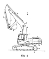
Fig. 5 , ahydraulic shovel 1 is a work machine provided with a lower structure, anupper swing body 3, acab 4, and awork device 5. The lower structure has right and lefttraveling devices 2 adapted to be respectively driven by right andleft travel motors 2m. Theupper swing body 3 is adapted to be rotated on the lower structure by aswing motor 3m. Thecab 4 and thework device 5 are mounted on theupper swing body 3. Thework device 5 comprises aboom 6 adapted to be vertically pivoted byboom cylinders 6c, astick 7 to be pivoted by a stick cylinder 7c, and abucket 8 to be pivoted by abucket cylinder 8c, wherein the base end of theboom 6 is supported at theupper swing body 3 by a shaft; thestick 7 is supported at the distal end of theboom 6 by a shaft; and thebucket 8 is supported at the distal end of thestick 7 by a shaft. - In the
cab 4 of a typical hydraulic shovel structured as above, traveling pedals and travel levers for operating the right and lefttraveling devices 2 of the lower structure are disposed on the floor in front of the operating seat. - Operating the traveling pedals with the feet is sufficient for broad travel operation but inadequate to perform fine operation. Therefore, when performing fine operation with a travel lever, it is necessary for the operator to remove a hand from one of the operating levers (work device/swing operating levers) that are disposed at the right and left sides of the operating seat respectively to rotate the
upper swing body 3 or thework device 5, and reach for the travel lever, which is disposed in front of the operator. - Furthermore, when separately operating the right and left travel levers, it is necessary to reach forward with both hands.
- Therefore, a structure that includes travel levers disposed in front of the operating seat may cause the travel levers to obstruct the operator from entering or exiting the
cab 4, or it compels the operator to change his position or shift his hand when operating a travel lever. - Some examples of conventionally known structures to solve the above problems include providing a travel control lever in the proximity of a work device/swing operating lever disposed at a side of the operating seat (e. g. See
Patent Documents - These structures facilitate entering and exiting of the operator but do not solve the problem of switching the hand from the operating lever to perform traveling operation. Moreover, sufficient space for installation of the travel lever has to be allotted at a side of the operating seat.
- Other structures are known, in which a switchover device is provided to enable one of the two work device/swing operating levers to serve as a travel lever (e. g. See
Patent Documents 5 and 6). - Furthermore, yet other structures are known, in which the right and left work device/swing operating levers are enabled to respectively and independently operate the right and left traveling devices (e. g. See
Patent Documents 4 and 7). - In any one of the structures that are offered in the Patent Documents mentioned above and include a switchover device provided separately from the operating levers, the operator has to remove his hand from an operating lever in order to operate the switchover device, which is nearly as inconvenient as switching one's hand from one lever to another. Even if the switchover device is attached to an operating lever, it is difficult for the operator to ascertain whether switchover has taken place, and the operator has to think about which device the operating lever has engaged for operation at the moment.
- Patent Document 1: Japanese Laid-open Patent Publication No.
6-136778 page 4 and Fig. 9) - Patent Document 2: Japanese Laid-open Patent Publication No.
7-32901 page 3 andFig. 2 ) - Patent Document 3: Japanese Laid-open Patent Publication No.
2002-323931 page 4 andFig. 1 ) - Patent Document 4: Japanese Laid-open Patent Publication No.
2004-100397 pages 7 and 15-17, andFigs. 1 and 11) - Patent Document 5: Japanese Laid-open Patent Publication No.
7-119710 Fig. 1 ) - Patent Document 6: Japanese Laid-open Patent Publication No.
2000-27238 Fig. 1 ) - Patent Document 7: Japanese Laid-open Patent Publication No.
H09-165788 Figs. 3-4 ) - As described above, a work machine having travel levers disposed on the floor in front of the operating seat not only makes it difficult for the operator to enter or exist the machine but also compels the operator to change his position or shift his hand when operating a travel lever. Even if a switchover device is provided separately from the operating levers, the operator has to remove his hand from an operating lever in order to operate the switchover device.
- In cases where an operating lever is provided with a switchover device so that switching the switchover device enables travel operation through a work device/swing operating lever, it is difficult for the operator to ascertain whether switchover has taken place.
- This may result in a situation such as the operator operating the operating lever by mistake, causing the work device to move when travel operation is intended, or erroneously causing travel operation while intending to operate the work device.
- In order to solve the above problems, an object of the invention is to provide a work machine equipped with a switchover means enabling selective operation of a traveling device and a work device by means of a common operating lever, wherein switchover can easily be performed and also easily recognized.
- The present invention according to
Claim 1 relates to a work machine having a traveling device and a work device, wherein the work machine includes an operating seat; an operating lever disposed at a side of the operating seat and able to operate the traveling device and the work device; a foot-operated switchover means disposed in the proximity of and operable with a foot of an operator seated at the operating seat; and a controller adapted to control the traveling device through the operating lever while the foot-operated switchover means is being operated with the foot, and control the work device through the operating lever while the foot-operated switchover means is not being operated. - The present invention according to
Claim 2 relates to the work machine ofClaim 1, wherein the work machine further includes a traveling alarm adapted to be activated when the foot-operated switchover means is operated with the foot. - The present invention according to
Claim 3 relates to the work machine ofClaim 1 orClaim 2, wherein the work machine further includes a traveling pedal adapted to be operated with a foot of the operator seated at the operating seat; and a warning alarm adapted to be activated when the traveling pedal and the foot-operated switchover means are simultaneously operated with the foot. - According to the present invention of
Claim 1, the foot-operated switchover means, which serves to enable the common operating lever to operate the traveling device and the work device, is disposed in the proximity of and operable with a foot of an operator seated at the operating seat. Therefore, switchover can easily be performed and it can also be easily recognized that switchover has taken place. In other words, by operating the foot-operated switchover means with his foot, the operator is able to perform travel operation consciously with the operating lever. By simply removing the foot from the foot-operated switchover means, the operator is able to return the machine to the normal operation mode without having to release his hand from the operating lever. - According to the present invention of
Claim 2, whenever the foot-operated switchover means is stepped on, the foot-operated switchover means activates the traveling alarm, making the operator fully aware that travel operation is being performed with the operating lever. Furthermore, the traveling alarm is sounded prior to travel action taking place by the operating lever, allowing ample time to alert people in the vicinity. - According to the present invention of
Claim 3, should the traveling pedal and the foot-operated switchover means be simultaneously stepped on, the warning alarm is activated to prevent a mix-up that would otherwise be caused by simultaneous commands for travel operation from the traveling pedal and the operating lever. -
-
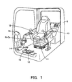
Fig. 1 is a perspective view showing a configuration of the interior of the cab of a work machine according to an embodiment of the present invention. -
Fig. 2 is a block diagram of a travel control system of the work machine. -
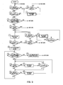
Fig. 3 is a flow chart showing an example of a control process of the travel control system. -
Fig. 4 is a flow chart showing another example of a control process of the travel control system. -
Fig. 5 is a side view of the work machine. -
- 1
- hydraulic shovel as a work machine
- 2
- traveling device
- 5
- work device
- 11
- operating seat
- 12
- traveling pedal
- 13
- operating lever
- 14
- foot switch as a foot-operated switchover means
- 16
- controller
- 21
- traveling alarm
- 22
- warning alarm
- Next, the present invention is explained in detail hereunder, referring to an embodiment thereof and an example of a control process shown in
Figs. 1 through 3 , another example of the control process shown inFig. 4 , and a work machine shown inFig. 5 . However, as the work machine shown inFig. 5 has already been explained, a detailed explanation is not given hereunder. - As shown in
Fig. 5 , ahydraulic shovel 1 is a work machine having travelingdevices 2 and awork device 5. As shown inFig. 1 , thehydraulic shovel 1 has acab 4, in which two travelingpedals 12 for the right and left travelingdevices 2 are disposed on the floor in front of an operatingseat 11, and two operating levers (joystick levers) 13 that are capable of operating the travelingdevice 2 and thework device 5 are disposed at the right and left sides of the operatingseat 11 respectively. The travel levers that are integrally included with the travelingpedals 12 in a conventional configuration are not provided. - A
foot switch 14 serving as a foot-operated switchover means is disposed in the proximity of a foot of an operator seated at the operatingseat 11, in other words on the floor in front of the right console R-Co shown inFig. 1 , so that the operator can operate thefoot switch 14 with his foot. Amonitor 15 equipped with an input device is provided diagonally in front of thefoot switch 14. - As shown in
Fig. 2 , the travelingpedals 12, the operating levers 13, and thefoot switch 14 are connected to the input side of acontroller 16.Travel control valves 17 are provided to respectively control the right and lefttravel motors 2m. Eachtravel control valve 17 has an electromagnetic operation unit connected to the output side of thecontroller 16. Ahydraulic pump 18 for feeding hydraulic oil through the hydraulic line and atank 19 for recovering return oil are connected to oil supply ports and oil discharge ports of thetravel control valves 17. - The
controller 16 serves to control the travelingdevices 2 through the operating levers 13 while the operator is operating thefoot switch 14 with his foot, and control thework device 5 through the operating levers 13 while thefoot switch 14 is not being operated. When controlling the travelingdevices 2 through the operating levers 13, thecontroller 16 performs control so that operating either operatinglever 13 forward or rearward enables thecorresponding travel motor 2m to function for forward or reverse travel. - A traveling
alarm 21 and awarning alarm 22 are connected to thecontroller 16. The travelingalarm 21 is adapted to be activated when the operator operates thefoot switch 14 with a foot, and thewarning alarm 22 is adapted to be activated should an operation error occur. The travelingalarm 21 and thewarning alarm 22 are provided as a part of themonitor 15 or other appropriate equipment. - Next, an example of a control process of the travel control system by the
controller 16 is explained hereunder, based on the flow chart shown inFig. 3 . In the drawing, numerals enclosed with circles represent step numbers. - (Step 1)
Whether or not a travelingpedal 12 has been operated is determined: - (Step 2)
If operation of at least one travelingpedal 12 is ascertained inStep 1, whether or not thefoot switch 14 has been stepped on is determined. If thefoot switch 14 is not depressed, the process returns to Step 1. - (Step 3)
If operation of at least one travelingpedal 12 is ascertained inStep 1, and operation of thefoot switch 14 is ascertained inStep 2, thewarning alarm 22 is activated. - (Step 4)
If neither travelingpedal 12 is ascertained inStep 1 to have been operated, whether or not an operatinglever 13 has been operated is determined. If operation of at least one operatinglever 13 is ascertained, the process returns to Step 2. - (Step 5)
If neither operatinglever 13 is ascertained inStep 4 to have been operated, whether or not the operating levers 13 have been at the neutral position, at which the operating levers 13 are not being operated, for a predetermined period of time is determined. Until the predetermined period of time elapses, the process keeps returning toStep 1. - (Step 6)
If it is ascertained inStep 5 that the operating levers 13 have been at the neutral position for the predetermined period of time, whether or not thefoot switch 14 has been stepped on is determined. If thefoot switch 14 is not depressed, the process returns to Step 1. - (Step 7)
If operation of thefoot switch 14 is ascertained inStep 6, the travelingalarm 21 is activated. The travelingalarm 21 provides an alarm not as a warning that an erroneous action has been taken but only to provide indication that thefoot switch 14 is stepped on. - (Step 8)
Whether or not an operatinglever 13 has been operated is determined. - (Step 9)
If neither operatinglever 13 is ascertained inStep 8 to have been operated, whether or not thefoot switch 14 has been stepped on is determined. If thefoot switch 14 is not depressed, the process returns to Step 1. - (Step 10)
If operation of thefoot switch 14 is ascertained in Step 9, whether or not a travelingpedal 12 has been stepped on is determined. If neither travelingpedal 12 has been stepped on, the process returns to Step 7. - (Step 11)
If operation of thefoot switch 14 is ascertained in Step 9, and operation of at least one travelingpedal 12 is ascertained inStep 10, thewarning alarm 22 is activated. - (Step 12)
Whether or not an operatinglever 13 has been operated is determined. If operation of at least one operatinglever 13 is ascertained, thewarning alarm 22 continues to sound. If neither operatinglever 13 is ascertained to have been operated, the process returns to Step 7. - (Step 13)
If operation of at least one operatinglever 13 is ascertained inStep 8, a joystick lever traveling mode is initiated, enabling the operating levers 13 to control thetravel control valves 17 so as to operate thetravel motors 2m. - (Step 14)
Whether or not the operating levers 13 have been at the neutral position, at which the operating levers 13 are not being operated, for a predetermined period of time is determined. - (Step 15)
If it is ascertained that the operating levers 13 have been at the neutral position for the predetermined period of time, the joystick lever traveling mode is deactivated, and the process returns to Step 1. - (Step 16)
If it is ascertained inStep 14 that the operating levers 13 have been at the neutral position, but the predetermined period of time has not yet elapsed, determination of whether or not thefoot switch 14 has been stepped on continues until the predetermined period of time elapses. - (Step 17)
If it is ascertained inStep 16 that thefoot switch 14 is not depressed, thewarning alarm 22 is activated. - (Step 18)
Whether or not an operatinglever 13 has been operated is determined. If operation of at least one operatinglever 13 is ascertained, the process returns to Step 16. If neither operatinglever 13. is ascertained to have been operated, the process proceeds to the next step, i.e.Step 19. - (Step 19)
Whether or not a travelingpedal 12 has been operated is determined. If neither travelingpedal 12 has been operated, the process keeps returning toStep 14. - (Step 20)
If operation of at least one travelingpedal 12 is ascertained inStep 19, thewarning alarm 22 is activated, and the process returns to Step 16. - Next, another example of a control process of the travel control system by the
controller 16 is explained hereunder, based on the flow chart shown inFig. 4 . In the drawing, numerals enclosed with circles represent step numbers. - (Step 21)
Whether or not a traveling pedal :12 has been operated is determined: - (Step 22)
If operation of at least one travelingpedal 12 is ascertained inStep 21, whether or not thefoot switch 14 has been stepped on is determined. If thefoot switch 14 is not depressed, the process returns to Step 21. - (Step 23)
If operation of at least one travelingpedal 12 is ascertained inStep 21, and operation of thefoot switch 14 is ascertained inStep 22, thewarning alarm 22 is activated. - (Step 24)
If neither travelingpedal 12 is ascertained inStep 21 to have been operated, whether or not an operatinglever 13 has been operated is determined. If at least one operatinglever 13 has been operated, the process returns to Step 22. - (Step 25)
If neither operatinglever 13 is ascertained inStep 24 to have been operated, whether or not the operating levers 13 have been at the neutral position, at which the operating levers 13 are not being operated, for a predetermined period of time is determined. Until the predetermined period of time elapses, the process keeps returning toStep 21. - (Step 26)
If it is ascertained inStep 25 that the operating levers 13 have been at the neutral position for the predetermined period of time, whether or not thefoot switch 14 has been stepped on is determined. If thefoot switch 14 is not depressed, the process returns to Step 21. - (Step 27)
If operation of thefoot switch 14 is ascertained inStep 26, the travelingalarm 21 is activated. - (Step 28)
Whether or not an operatinglever 13 has been operated is determined. - (Step 29)
If neither operatinglever 13 is ascertained inStep 28 to have been operated, whether or not thefoot switch 14 has been stepped on is determined. If operation of thefoot switch 14 is ascertained, the process returns to Step 27. - (Step 30)
If it is ascertained inStep 29 that thefoot switch 14 is not depressed, a stop mode is initiated. - (Step 31)
When the stop mode is initiated, function of the hydraulic shovel is halted. - (Step 32)
Whether or not a travelingpedal 12 has been operated is determined. - (Step 33)
If neither travelingpedal 12 is ascertained inStep 32 to have been operated, whether or not an operatinglever 13 has been operated is determined. - (Step 34)
If neither operatinglever 13 is ascertained inStep 33 to have been operated, whether or not thefoot switch 14 has been operated is determined. - (Step 35)
If any one of the following components, namely the travelingpedals 12, the operating levers 13, and thefoot switch 14, has been operated, thewarning alarm 22 is activated, and the process returns to Step 32. - (Step 36)
If it is ascertained inStep 34 that thefoot switch 14 has not been stepped on, whether or not a predetermined period of time has elapsed is determined. Until the predetermined period of time elapses, the process keeps returning toStep 32. When the predetermined period of time has elapsed, the process returns to Step 21. - (Step 37)
If operation of at least one operatinglever 13 is ascertained inStep 28, the joystick lever traveling mode is initiated, enabling the operating levers 13 to control thetravel control valves 17 so as to operate thetravel motors 2m. - (Step 38)
Whether or not the operating levers 13 have been at the neutral position, at which the operating levers 13 are not being operated, for a predetermined period of time is determined. - (Step 39)
If it is ascertained that the operating levers 13 have been at the neutral position for the predetermined period of time, the joystick lever traveling mode is deactivated, and the process returns to Step 21. - (Step 40)
If it is ascertained inStep 38 that the operating levers 13 have been at the neutral position, but the predetermined period of time has not yet elapsed, whether or not thefoot switch 14 has been operated is determined. If thefoot switch 14 is depressed, the process returns to Step 38. If thefoot switch 14 is not depressed, the stop mode is initiated. - Next, functions and effects of the embodiment described above are explained.
- While the
foot switch 14 is not depressed, the operating levers 13 serve to perform normal actions, in other words, to operate the work device and/or perform swing action, and the travelingpedals 12, too, serve to operate the travel systems in a normal manner. To be more specific, aswing motor 3m,boom cylinders 6c, a stick cylinder 7c, and abucket cylinder 8c are operated by the operating levers 13, and the right and lefttravel motors 2m are operated by means of the right and left travelingpedals 12. - The
hydraulic shovel 1 is not provided with travel levers, which: would otherwise be disposed in front of the operating seat of a conventional hydraulic shovel. Therefore, instead of the eliminated travel levers, thefoot switch 14 provided at the feet of the operator is stepped on to cause the right and left operating levers 13, which normally serve to operate the work device and perform swing action, to function as travel control levers so as to respectively control operation of the right and lefttravel motors 2m. - To be more specific, moving the
left operating lever 13 forward causes theleft travel motor 2m to function for forward travel, and moving theleft operating lever 13 rearward causes theleft travel motor 2m to function for reverse travel. Moving theright operating lever 13 forward causes theright travel motor 2m to function for forward travel, and moving theright operating lever 13 rearward causes theright travel motor 2m to function for reverse travel. - As described above, while the
foot switch 14 is depressed, the travelingpedals 12 are prevented from functioning so that travel operation can be performed only by the operating levers 13. When thefoot switch 14 is stepped on, the travelingalarm 21 sounds an alarm. Should an operation error, such as stepping on both thefoot switch 14 and a travelingpedal 12, occur, thewarning alarm 22 sounds an alarm. - As described above, the
foot switch 14, which serves to enable thecommon operating levers 13 to operate the travelingdevices 2 and thework device 5, is disposed in the proximity of and operable with a foot of an operator seated at the operatingseat 11. Therefore, switchover can easily be performed and it can also be easily recognized that switchover has taken place. - In other words, by operating the
foot switch 14 with his foot, the operator is able to perform travel operation consciously with the operating levers 13. By simply removing the foot from thefoot switch 14, the operator is able to return the machine to the normal operation mode without having to release his hands from the operating levers 13. Thus, the invention described above provides superior functionality that greatly simplifies switchover. - A particular merit of the embodiment is that, whenever the
foot switch 14 is stepped on, thefoot switch 14 activates the travelingalarm 21, making the operator fully aware that travel operation is being performed with the operating levers 13. Furthermore, the travelingalarm 21 is sounded prior to travel action taking place by the operating levers 13, allowing ample time to alert people in the vicinity. - Furthermore, should a traveling
pedal 12 and thefoot switch 14 be simultaneously stepped on, thewarning alarm 22 is activated to prevent a mix-up that would otherwise be caused by simultaneous commands for travel operation from the travelingpedal 12 and an operatinglever 13. - The foot-operated switchover means is not limited to the foot switch 14: for example, if a pedal similar to an attachment pedal for operating a breaker or a crusher or other attachment that is attached in place of the
bucket 8 is provided at a side of a travelingpedal 12, such a pedal may serve as the foot-operated switchover means in place of thefoot switch 14. - The present invention is applicable not only to a rotary-type work machine, such as the
hydraulic shovel 1, but also to any work machine that has a travelingdevice 2 and awork device 5.
Claims (3)
- A work machine having a traveling device and a work device, comprising:an operating seat;an operating lever disposed at a side of the operating seat and able to operate the traveling device and the work device;a foot-operated switchover means disposed in the proximity of and operable with a foot of an operator seated at the operating seat; anda controller adapted to control the traveling device through the operating lever while the foot-operated switchover means is being operated with the foot, and control the work device through the operating lever while the foot-operated switchover means is not being operated.
- The work machine in accordance with Claim 1, further comprising:a traveling alarm adapted to be activated when the foot-operated switchover means is operated with the foot.
- The work machine in accordance with Claim 1 or Claim 2, further comprising:a traveling pedal adapted to be operated with a foot of the operator seated at the operating seat; anda warning alarm adapted to be activated when the traveling pedal and the foot-operated switchover means are simultaneously operated with the foot.
Applications Claiming Priority (2)
| Application Number | Priority Date | Filing Date | Title |
|---|---|---|---|
| JP2005349063A JP4091955B2 (en) | 2005-12-02 | 2005-12-02 | Work machine |
| PCT/JP2006/318580 WO2007063634A1 (en) | 2005-12-02 | 2006-09-20 | Working machine |
Publications (1)
| Publication Number | Publication Date |
|---|---|
| EP1956148A1 true EP1956148A1 (en) | 2008-08-13 |
Family
ID=38091974
Family Applications (1)
| Application Number | Title | Priority Date | Filing Date |
|---|---|---|---|
| EP06798140A Withdrawn EP1956148A1 (en) | 2005-12-02 | 2006-09-20 | Working machine |
Country Status (5)
| Country | Link |
|---|---|
| US (1) | US7854291B2 (en) |
| EP (1) | EP1956148A1 (en) |
| JP (1) | JP4091955B2 (en) |
| DE (1) | DE06798140T1 (en) |
| WO (1) | WO2007063634A1 (en) |
Families Citing this family (19)
| Publication number | Priority date | Publication date | Assignee | Title |
|---|---|---|---|---|
| JP4206099B2 (en) * | 2005-12-12 | 2009-01-07 | キャタピラージャパン株式会社 | Work machine |
| US8392049B2 (en) * | 2006-07-17 | 2013-03-05 | Nmhg Oregon, Llc | Multi-direction vehicle control sensing |
| US8235161B2 (en) | 2007-07-06 | 2012-08-07 | Nmhg Oregon, Llc | Multiple-position steering control device |
| USD664998S1 (en) * | 2011-12-01 | 2012-08-07 | Harnischfeger Technologies, Inc. | Seat module |
| USD685007S1 (en) * | 2012-05-10 | 2013-06-25 | Hitachi Construction Machinery Co., Ltd. | Seat for operator cab for construction machine |
| DE202014009101U1 (en) | 2013-11-19 | 2015-02-09 | Nacco Materials Handling Group, Inc. | Backward control handle for a forklift |
| JP1534397S (en) * | 2015-04-16 | 2015-10-05 | ||
| JP1556401S (en) * | 2016-01-08 | 2016-08-15 | ||
| JP6466865B2 (en) * | 2016-02-17 | 2019-02-06 | 日立建機株式会社 | Safety equipment for construction machinery |
| JP6577433B2 (en) * | 2016-09-15 | 2019-09-18 | 日立建機株式会社 | Wheeled excavator |
| JP1615679S (en) * | 2017-11-22 | 2019-10-07 | ||
| JP1612267S (en) * | 2017-11-22 | 2021-08-23 | ||
| JP1612266S (en) * | 2017-11-22 | 2021-08-23 | ||
| JP1612268S (en) * | 2017-11-22 | 2021-08-23 | ||
| JP6940118B2 (en) * | 2019-01-31 | 2021-09-22 | 株式会社三井E&Sマシナリー | Crane operation support system |
| USD920388S1 (en) * | 2019-04-30 | 2021-05-25 | Spohn & Burkhardt GmbH & Co. KG | Control unit |
| USD1060439S1 (en) * | 2021-11-19 | 2025-02-04 | Manitou Italia S.R.L. | Console with hand controls for telescopic lifter |
| CN114960825A (en) * | 2022-07-26 | 2022-08-30 | 雷沃工程机械集团有限公司 | Hydraulic circuit for controlling excavator to walk by using handle |
| DE102022208965A1 (en) * | 2022-08-30 | 2024-02-29 | Kässbohrer Geländefahrzeug Aktiengesellschaft | Civilian tracked vehicle |
Family Cites Families (18)
| Publication number | Priority date | Publication date | Assignee | Title |
|---|---|---|---|---|
| JPH06136778A (en) | 1992-10-21 | 1994-05-17 | Yanmar Diesel Engine Co Ltd | All-round rotary type excavator |
| JPH0732901A (en) | 1993-07-14 | 1995-02-03 | Komatsu Ltd | Traveling equipment for construction machinery |
| JP3534350B2 (en) | 1993-10-27 | 2004-06-07 | 株式会社小松製作所 | Travel operating device |
| US5422521A (en) * | 1993-11-18 | 1995-06-06 | Liebel-Flarsheim Co. | Foot operated control system for a multi-function device |
| JPH09165788A (en) | 1995-12-19 | 1997-06-24 | Sumitomo Constr Mach Co Ltd | Control lever controlling circuit for construction machine |
| JP3779825B2 (en) | 1998-07-09 | 2006-05-31 | 日立建機株式会社 | Traveling operation device for hydraulic traveling vehicle |
| US6854554B2 (en) * | 2000-12-15 | 2005-02-15 | Clark Equipment Company | Joystick steering on power machine with filtered steering input |
| JP2002323931A (en) | 2001-04-26 | 2002-11-08 | Komatsu Ltd | Hydraulic excavator |
| JP2003049455A (en) | 2001-08-07 | 2003-02-21 | Hitachi Constr Mach Co Ltd | Alarm device for construction machine |
| DE10140975A1 (en) * | 2001-08-27 | 2003-03-20 | Claas Selbstfahr Erntemasch | Device for controlling an agricultural vehicle |
| JP3900912B2 (en) * | 2001-12-05 | 2007-04-04 | 株式会社豊田自動織機 | Industrial vehicle |
| JP2004100397A (en) | 2002-09-12 | 2004-04-02 | Komatsu Ltd | Driving operation device for industrial vehicles |
| US6971470B2 (en) * | 2003-07-31 | 2005-12-06 | The Raymond Corporation | Control system for material handling vehicle with dual control handles |
| US7334658B2 (en) * | 2004-12-23 | 2008-02-26 | Caterpillar Inc. | Steering system with joystick mounted controls |
| US7516811B2 (en) * | 2005-02-22 | 2009-04-14 | Gm Global Technology Operations, Inc. | Vehicle accessory pedal and method |
| JP4206099B2 (en) * | 2005-12-12 | 2009-01-07 | キャタピラージャパン株式会社 | Work machine |
| ATE544914T1 (en) * | 2006-03-30 | 2012-02-15 | Charles Machine Works | CONTROL SYSTEM WITH MULTIPLE FUNCTIONS FOR A WORK MACHINE |
| US7729835B2 (en) * | 2007-08-21 | 2010-06-01 | Jcb Compact Products Limited | Method of controlling a working machine |
-
2005
- 2005-12-02 JP JP2005349063A patent/JP4091955B2/en not_active Expired - Fee Related
-
2006
- 2006-09-20 EP EP06798140A patent/EP1956148A1/en not_active Withdrawn
- 2006-09-20 DE DE06798140T patent/DE06798140T1/en active Pending
- 2006-09-20 WO PCT/JP2006/318580 patent/WO2007063634A1/en not_active Ceased
- 2006-09-20 US US12/095,027 patent/US7854291B2/en not_active Expired - Fee Related
Non-Patent Citations (1)
| Title |
|---|
| See references of WO2007063634A1 * |
Also Published As
| Publication number | Publication date |
|---|---|
| DE06798140T1 (en) | 2008-12-04 |
| US7854291B2 (en) | 2010-12-21 |
| WO2007063634A1 (en) | 2007-06-07 |
| US20100000367A1 (en) | 2010-01-07 |
| JP2007154473A (en) | 2007-06-21 |
| JP4091955B2 (en) | 2008-05-28 |
Similar Documents
| Publication | Publication Date | Title |
|---|---|---|
| EP1956148A1 (en) | Working machine | |
| US9670939B2 (en) | Operation control system | |
| US9217240B2 (en) | Work vehicle, work vehicle display device, method of controlling work vehicle display device, backhoe loader, backhoe loader display device, and method of controlling backhoe loader display device | |
| US7730646B2 (en) | Swivel work machine | |
| KR101654117B1 (en) | Work vehicle and work vehicle control method | |
| WO2017047654A1 (en) | Shovel | |
| US8028787B2 (en) | Work machine | |
| EP3904607A1 (en) | Operating mechanism for work machine and work machine equipped with same | |
| JP4025676B2 (en) | Work machine input device | |
| EP3771775A1 (en) | Machine control system for operating a construction machine | |
| CN104520596A (en) | Hydraulic system for construction machinery | |
| JP3661596B2 (en) | Construction machine operation circuit | |
| JP7326796B2 (en) | working machine | |
| JPH09165797A (en) | Working machine operating device | |
| JP2007120222A (en) | Wheel type construction machine | |
| JPH11324026A (en) | Operator and actuator combination changing device and work mode changing device in construction machinery | |
| JP4322263B2 (en) | Construction machine control device | |
| JP3481009B2 (en) | Cargo handling equipment for cargo handling vehicles | |
| JP3670750B2 (en) | Working equipment operating device for hydraulic construction machines | |
| US20250003186A1 (en) | Work Machine | |
| GB2570184A (en) | Device and method for controlling a working machine | |
| KR20250123915A (en) | work machine | |
| JPH0863248A (en) | Misoperation prevention device for operating device | |
| JP2002322678A (en) | Emergency switch | |
| JP2011137345A (en) | Monitoring device for construction machine |
Legal Events
| Date | Code | Title | Description |
|---|---|---|---|
| PUAI | Public reference made under article 153(3) epc to a published international application that has entered the european phase |
Free format text: ORIGINAL CODE: 0009012 |
|
| 17P | Request for examination filed |
Effective date: 20080519 |
|
| AK | Designated contracting states |
Kind code of ref document: A1 Designated state(s): BE DE FR |
|
| EL | Fr: translation of claims filed | ||
| RAP1 | Party data changed (applicant data changed or rights of an application transferred) |
Owner name: CATERPILLAR JAPAN LTD. |
|
| DET | De: translation of patent claims | ||
| DAX | Request for extension of the european patent (deleted) | ||
| RBV | Designated contracting states (corrected) |
Designated state(s): BE DE FR |
|
| RAP1 | Party data changed (applicant data changed or rights of an application transferred) |
Owner name: CATERPILLAR SARL |
|
| STAA | Information on the status of an ep patent application or granted ep patent |
Free format text: STATUS: THE APPLICATION HAS BEEN WITHDRAWN |
|
| 18W | Application withdrawn |
Effective date: 20101213 |