EP1955887A2 - Attaching a component to an internal surface of a tank formed of polymer - Google Patents
Attaching a component to an internal surface of a tank formed of polymer Download PDFInfo
- Publication number
- EP1955887A2 EP1955887A2 EP20080250458 EP08250458A EP1955887A2 EP 1955887 A2 EP1955887 A2 EP 1955887A2 EP 20080250458 EP20080250458 EP 20080250458 EP 08250458 A EP08250458 A EP 08250458A EP 1955887 A2 EP1955887 A2 EP 1955887A2
- Authority
- EP
- European Patent Office
- Prior art keywords
- tank
- polymer
- component
- weld
- wall
- Prior art date
- Legal status (The legal status is an assumption and is not a legal conclusion. Google has not performed a legal analysis and makes no representation as to the accuracy of the status listed.)
- Granted
Links
Images


Classifications
-
- B—PERFORMING OPERATIONS; TRANSPORTING
- B60—VEHICLES IN GENERAL
- B60K—ARRANGEMENT OR MOUNTING OF PROPULSION UNITS OR OF TRANSMISSIONS IN VEHICLES; ARRANGEMENT OR MOUNTING OF PLURAL DIVERSE PRIME-MOVERS IN VEHICLES; AUXILIARY DRIVES FOR VEHICLES; INSTRUMENTATION OR DASHBOARDS FOR VEHICLES; ARRANGEMENTS IN CONNECTION WITH COOLING, AIR INTAKE, GAS EXHAUST OR FUEL SUPPLY OF PROPULSION UNITS IN VEHICLES
- B60K15/00—Arrangement in connection with fuel supply of combustion engines or other fuel consuming energy converters, e.g. fuel cells; Mounting or construction of fuel tanks
- B60K15/03—Fuel tanks
- B60K15/03177—Fuel tanks made of non-metallic material, e.g. plastics, or of a combination of non-metallic and metallic material
-
- B—PERFORMING OPERATIONS; TRANSPORTING
- B29—WORKING OF PLASTICS; WORKING OF SUBSTANCES IN A PLASTIC STATE IN GENERAL
- B29C—SHAPING OR JOINING OF PLASTICS; SHAPING OF MATERIAL IN A PLASTIC STATE, NOT OTHERWISE PROVIDED FOR; AFTER-TREATMENT OF THE SHAPED PRODUCTS, e.g. REPAIRING
- B29C65/00—Joining or sealing of preformed parts, e.g. welding of plastics materials; Apparatus therefor
- B29C65/02—Joining or sealing of preformed parts, e.g. welding of plastics materials; Apparatus therefor by heating, with or without pressure
- B29C65/14—Joining or sealing of preformed parts, e.g. welding of plastics materials; Apparatus therefor by heating, with or without pressure using wave energy, i.e. electromagnetic radiation, or particle radiation
- B29C65/1429—Joining or sealing of preformed parts, e.g. welding of plastics materials; Apparatus therefor by heating, with or without pressure using wave energy, i.e. electromagnetic radiation, or particle radiation characterised by the way of heating the interface
- B29C65/1435—Joining or sealing of preformed parts, e.g. welding of plastics materials; Apparatus therefor by heating, with or without pressure using wave energy, i.e. electromagnetic radiation, or particle radiation characterised by the way of heating the interface at least passing through one of the parts to be joined, i.e. transmission welding
-
- B—PERFORMING OPERATIONS; TRANSPORTING
- B29—WORKING OF PLASTICS; WORKING OF SUBSTANCES IN A PLASTIC STATE IN GENERAL
- B29C—SHAPING OR JOINING OF PLASTICS; SHAPING OF MATERIAL IN A PLASTIC STATE, NOT OTHERWISE PROVIDED FOR; AFTER-TREATMENT OF THE SHAPED PRODUCTS, e.g. REPAIRING
- B29C65/00—Joining or sealing of preformed parts, e.g. welding of plastics materials; Apparatus therefor
- B29C65/02—Joining or sealing of preformed parts, e.g. welding of plastics materials; Apparatus therefor by heating, with or without pressure
- B29C65/14—Joining or sealing of preformed parts, e.g. welding of plastics materials; Apparatus therefor by heating, with or without pressure using wave energy, i.e. electromagnetic radiation, or particle radiation
- B29C65/1477—Joining or sealing of preformed parts, e.g. welding of plastics materials; Apparatus therefor by heating, with or without pressure using wave energy, i.e. electromagnetic radiation, or particle radiation making use of an absorber or impact modifier
- B29C65/148—Joining or sealing of preformed parts, e.g. welding of plastics materials; Apparatus therefor by heating, with or without pressure using wave energy, i.e. electromagnetic radiation, or particle radiation making use of an absorber or impact modifier placed at the interface
-
- B—PERFORMING OPERATIONS; TRANSPORTING
- B29—WORKING OF PLASTICS; WORKING OF SUBSTANCES IN A PLASTIC STATE IN GENERAL
- B29C—SHAPING OR JOINING OF PLASTICS; SHAPING OF MATERIAL IN A PLASTIC STATE, NOT OTHERWISE PROVIDED FOR; AFTER-TREATMENT OF THE SHAPED PRODUCTS, e.g. REPAIRING
- B29C65/00—Joining or sealing of preformed parts, e.g. welding of plastics materials; Apparatus therefor
- B29C65/02—Joining or sealing of preformed parts, e.g. welding of plastics materials; Apparatus therefor by heating, with or without pressure
- B29C65/14—Joining or sealing of preformed parts, e.g. welding of plastics materials; Apparatus therefor by heating, with or without pressure using wave energy, i.e. electromagnetic radiation, or particle radiation
- B29C65/1477—Joining or sealing of preformed parts, e.g. welding of plastics materials; Apparatus therefor by heating, with or without pressure using wave energy, i.e. electromagnetic radiation, or particle radiation making use of an absorber or impact modifier
- B29C65/1483—Joining or sealing of preformed parts, e.g. welding of plastics materials; Apparatus therefor by heating, with or without pressure using wave energy, i.e. electromagnetic radiation, or particle radiation making use of an absorber or impact modifier coated on the article
-
- B—PERFORMING OPERATIONS; TRANSPORTING
- B29—WORKING OF PLASTICS; WORKING OF SUBSTANCES IN A PLASTIC STATE IN GENERAL
- B29C—SHAPING OR JOINING OF PLASTICS; SHAPING OF MATERIAL IN A PLASTIC STATE, NOT OTHERWISE PROVIDED FOR; AFTER-TREATMENT OF THE SHAPED PRODUCTS, e.g. REPAIRING
- B29C65/00—Joining or sealing of preformed parts, e.g. welding of plastics materials; Apparatus therefor
- B29C65/02—Joining or sealing of preformed parts, e.g. welding of plastics materials; Apparatus therefor by heating, with or without pressure
- B29C65/14—Joining or sealing of preformed parts, e.g. welding of plastics materials; Apparatus therefor by heating, with or without pressure using wave energy, i.e. electromagnetic radiation, or particle radiation
- B29C65/16—Laser beams
- B29C65/1629—Laser beams characterised by the way of heating the interface
- B29C65/1635—Laser beams characterised by the way of heating the interface at least passing through one of the parts to be joined, i.e. laser transmission welding
-
- B—PERFORMING OPERATIONS; TRANSPORTING
- B29—WORKING OF PLASTICS; WORKING OF SUBSTANCES IN A PLASTIC STATE IN GENERAL
- B29C—SHAPING OR JOINING OF PLASTICS; SHAPING OF MATERIAL IN A PLASTIC STATE, NOT OTHERWISE PROVIDED FOR; AFTER-TREATMENT OF THE SHAPED PRODUCTS, e.g. REPAIRING
- B29C65/00—Joining or sealing of preformed parts, e.g. welding of plastics materials; Apparatus therefor
- B29C65/02—Joining or sealing of preformed parts, e.g. welding of plastics materials; Apparatus therefor by heating, with or without pressure
- B29C65/14—Joining or sealing of preformed parts, e.g. welding of plastics materials; Apparatus therefor by heating, with or without pressure using wave energy, i.e. electromagnetic radiation, or particle radiation
- B29C65/16—Laser beams
- B29C65/1677—Laser beams making use of an absorber or impact modifier
- B29C65/168—Laser beams making use of an absorber or impact modifier placed at the interface
-
- B—PERFORMING OPERATIONS; TRANSPORTING
- B29—WORKING OF PLASTICS; WORKING OF SUBSTANCES IN A PLASTIC STATE IN GENERAL
- B29C—SHAPING OR JOINING OF PLASTICS; SHAPING OF MATERIAL IN A PLASTIC STATE, NOT OTHERWISE PROVIDED FOR; AFTER-TREATMENT OF THE SHAPED PRODUCTS, e.g. REPAIRING
- B29C65/00—Joining or sealing of preformed parts, e.g. welding of plastics materials; Apparatus therefor
- B29C65/02—Joining or sealing of preformed parts, e.g. welding of plastics materials; Apparatus therefor by heating, with or without pressure
- B29C65/14—Joining or sealing of preformed parts, e.g. welding of plastics materials; Apparatus therefor by heating, with or without pressure using wave energy, i.e. electromagnetic radiation, or particle radiation
- B29C65/16—Laser beams
- B29C65/1677—Laser beams making use of an absorber or impact modifier
- B29C65/1683—Laser beams making use of an absorber or impact modifier coated on the article
-
- B—PERFORMING OPERATIONS; TRANSPORTING
- B29—WORKING OF PLASTICS; WORKING OF SUBSTANCES IN A PLASTIC STATE IN GENERAL
- B29C—SHAPING OR JOINING OF PLASTICS; SHAPING OF MATERIAL IN A PLASTIC STATE, NOT OTHERWISE PROVIDED FOR; AFTER-TREATMENT OF THE SHAPED PRODUCTS, e.g. REPAIRING
- B29C65/00—Joining or sealing of preformed parts, e.g. welding of plastics materials; Apparatus therefor
- B29C65/48—Joining or sealing of preformed parts, e.g. welding of plastics materials; Apparatus therefor using adhesives, i.e. using supplementary joining material; solvent bonding
-
- B—PERFORMING OPERATIONS; TRANSPORTING
- B29—WORKING OF PLASTICS; WORKING OF SUBSTANCES IN A PLASTIC STATE IN GENERAL
- B29C—SHAPING OR JOINING OF PLASTICS; SHAPING OF MATERIAL IN A PLASTIC STATE, NOT OTHERWISE PROVIDED FOR; AFTER-TREATMENT OF THE SHAPED PRODUCTS, e.g. REPAIRING
- B29C65/00—Joining or sealing of preformed parts, e.g. welding of plastics materials; Apparatus therefor
- B29C65/78—Means for handling the parts to be joined, e.g. for making containers or hollow articles, e.g. means for handling sheets, plates, web-like materials, tubular articles, hollow articles or elements to be joined therewith; Means for discharging the joined articles from the joining apparatus
- B29C65/7802—Positioning the parts to be joined, e.g. aligning, indexing or centring
- B29C65/7838—Positioning the parts to be joined, e.g. aligning, indexing or centring from the inside, e.g. of tubular or hollow articles
-
- B—PERFORMING OPERATIONS; TRANSPORTING
- B29—WORKING OF PLASTICS; WORKING OF SUBSTANCES IN A PLASTIC STATE IN GENERAL
- B29C—SHAPING OR JOINING OF PLASTICS; SHAPING OF MATERIAL IN A PLASTIC STATE, NOT OTHERWISE PROVIDED FOR; AFTER-TREATMENT OF THE SHAPED PRODUCTS, e.g. REPAIRING
- B29C66/00—General aspects of processes or apparatus for joining preformed parts
- B29C66/01—General aspects dealing with the joint area or with the area to be joined
- B29C66/05—Particular design of joint configurations
- B29C66/10—Particular design of joint configurations particular design of the joint cross-sections
- B29C66/11—Joint cross-sections comprising a single joint-segment, i.e. one of the parts to be joined comprising a single joint-segment in the joint cross-section
- B29C66/112—Single lapped joints
-
- B—PERFORMING OPERATIONS; TRANSPORTING
- B29—WORKING OF PLASTICS; WORKING OF SUBSTANCES IN A PLASTIC STATE IN GENERAL
- B29C—SHAPING OR JOINING OF PLASTICS; SHAPING OF MATERIAL IN A PLASTIC STATE, NOT OTHERWISE PROVIDED FOR; AFTER-TREATMENT OF THE SHAPED PRODUCTS, e.g. REPAIRING
- B29C66/00—General aspects of processes or apparatus for joining preformed parts
- B29C66/01—General aspects dealing with the joint area or with the area to be joined
- B29C66/05—Particular design of joint configurations
- B29C66/10—Particular design of joint configurations particular design of the joint cross-sections
- B29C66/13—Single flanged joints; Fin-type joints; Single hem joints; Edge joints; Interpenetrating fingered joints; Other specific particular designs of joint cross-sections not provided for in groups B29C66/11 - B29C66/12
- B29C66/131—Single flanged joints, i.e. one of the parts to be joined being rigid and flanged in the joint area
-
- B—PERFORMING OPERATIONS; TRANSPORTING
- B29—WORKING OF PLASTICS; WORKING OF SUBSTANCES IN A PLASTIC STATE IN GENERAL
- B29C—SHAPING OR JOINING OF PLASTICS; SHAPING OF MATERIAL IN A PLASTIC STATE, NOT OTHERWISE PROVIDED FOR; AFTER-TREATMENT OF THE SHAPED PRODUCTS, e.g. REPAIRING
- B29C66/00—General aspects of processes or apparatus for joining preformed parts
- B29C66/01—General aspects dealing with the joint area or with the area to be joined
- B29C66/348—Avoiding melting or weakening of the zone directly next to the joint area, e.g. by cooling
-
- B—PERFORMING OPERATIONS; TRANSPORTING
- B29—WORKING OF PLASTICS; WORKING OF SUBSTANCES IN A PLASTIC STATE IN GENERAL
- B29C—SHAPING OR JOINING OF PLASTICS; SHAPING OF MATERIAL IN A PLASTIC STATE, NOT OTHERWISE PROVIDED FOR; AFTER-TREATMENT OF THE SHAPED PRODUCTS, e.g. REPAIRING
- B29C66/00—General aspects of processes or apparatus for joining preformed parts
- B29C66/50—General aspects of joining tubular articles; General aspects of joining long products, i.e. bars or profiled elements; General aspects of joining single elements to tubular articles, hollow articles or bars; General aspects of joining several hollow-preforms to form hollow or tubular articles
- B29C66/51—Joining tubular articles, profiled elements or bars; Joining single elements to tubular articles, hollow articles or bars; Joining several hollow-preforms to form hollow or tubular articles
- B29C66/53—Joining single elements to tubular articles, hollow articles or bars
- B29C66/532—Joining single elements to the wall of tubular articles, hollow articles or bars
-
- B—PERFORMING OPERATIONS; TRANSPORTING
- B29—WORKING OF PLASTICS; WORKING OF SUBSTANCES IN A PLASTIC STATE IN GENERAL
- B29C—SHAPING OR JOINING OF PLASTICS; SHAPING OF MATERIAL IN A PLASTIC STATE, NOT OTHERWISE PROVIDED FOR; AFTER-TREATMENT OF THE SHAPED PRODUCTS, e.g. REPAIRING
- B29C66/00—General aspects of processes or apparatus for joining preformed parts
- B29C66/50—General aspects of joining tubular articles; General aspects of joining long products, i.e. bars or profiled elements; General aspects of joining single elements to tubular articles, hollow articles or bars; General aspects of joining several hollow-preforms to form hollow or tubular articles
- B29C66/61—Joining from or joining on the inside
-
- B—PERFORMING OPERATIONS; TRANSPORTING
- B29—WORKING OF PLASTICS; WORKING OF SUBSTANCES IN A PLASTIC STATE IN GENERAL
- B29C—SHAPING OR JOINING OF PLASTICS; SHAPING OF MATERIAL IN A PLASTIC STATE, NOT OTHERWISE PROVIDED FOR; AFTER-TREATMENT OF THE SHAPED PRODUCTS, e.g. REPAIRING
- B29C66/00—General aspects of processes or apparatus for joining preformed parts
- B29C66/70—General aspects of processes or apparatus for joining preformed parts characterised by the composition, physical properties or the structure of the material of the parts to be joined; Joining with non-plastics material
- B29C66/72—General aspects of processes or apparatus for joining preformed parts characterised by the composition, physical properties or the structure of the material of the parts to be joined; Joining with non-plastics material characterised by the structure of the material of the parts to be joined
- B29C66/723—General aspects of processes or apparatus for joining preformed parts characterised by the composition, physical properties or the structure of the material of the parts to be joined; Joining with non-plastics material characterised by the structure of the material of the parts to be joined being multi-layered
-
- B—PERFORMING OPERATIONS; TRANSPORTING
- B29—WORKING OF PLASTICS; WORKING OF SUBSTANCES IN A PLASTIC STATE IN GENERAL
- B29C—SHAPING OR JOINING OF PLASTICS; SHAPING OF MATERIAL IN A PLASTIC STATE, NOT OTHERWISE PROVIDED FOR; AFTER-TREATMENT OF THE SHAPED PRODUCTS, e.g. REPAIRING
- B29C66/00—General aspects of processes or apparatus for joining preformed parts
- B29C66/80—General aspects of machine operations or constructions and parts thereof
- B29C66/84—Specific machine types or machines suitable for specific applications
- B29C66/863—Robotised, e.g. mounted on a robot arm
-
- B—PERFORMING OPERATIONS; TRANSPORTING
- B29—WORKING OF PLASTICS; WORKING OF SUBSTANCES IN A PLASTIC STATE IN GENERAL
- B29C—SHAPING OR JOINING OF PLASTICS; SHAPING OF MATERIAL IN A PLASTIC STATE, NOT OTHERWISE PROVIDED FOR; AFTER-TREATMENT OF THE SHAPED PRODUCTS, e.g. REPAIRING
- B29C35/00—Heating, cooling or curing, e.g. crosslinking or vulcanising; Apparatus therefor
- B29C35/02—Heating or curing, e.g. crosslinking or vulcanizing during moulding, e.g. in a mould
- B29C35/08—Heating or curing, e.g. crosslinking or vulcanizing during moulding, e.g. in a mould by wave energy or particle radiation
- B29C35/0805—Heating or curing, e.g. crosslinking or vulcanizing during moulding, e.g. in a mould by wave energy or particle radiation using electromagnetic radiation
- B29C2035/0822—Heating or curing, e.g. crosslinking or vulcanizing during moulding, e.g. in a mould by wave energy or particle radiation using electromagnetic radiation using IR radiation
-
- B—PERFORMING OPERATIONS; TRANSPORTING
- B29—WORKING OF PLASTICS; WORKING OF SUBSTANCES IN A PLASTIC STATE IN GENERAL
- B29C—SHAPING OR JOINING OF PLASTICS; SHAPING OF MATERIAL IN A PLASTIC STATE, NOT OTHERWISE PROVIDED FOR; AFTER-TREATMENT OF THE SHAPED PRODUCTS, e.g. REPAIRING
- B29C2793/00—Shaping techniques involving a cutting or machining operation
- B29C2793/0009—Cutting out
- B29C2793/0018—Cutting out for making a hole
-
- B—PERFORMING OPERATIONS; TRANSPORTING
- B29—WORKING OF PLASTICS; WORKING OF SUBSTANCES IN A PLASTIC STATE IN GENERAL
- B29C—SHAPING OR JOINING OF PLASTICS; SHAPING OF MATERIAL IN A PLASTIC STATE, NOT OTHERWISE PROVIDED FOR; AFTER-TREATMENT OF THE SHAPED PRODUCTS, e.g. REPAIRING
- B29C2793/00—Shaping techniques involving a cutting or machining operation
- B29C2793/0081—Shaping techniques involving a cutting or machining operation before shaping
-
- B—PERFORMING OPERATIONS; TRANSPORTING
- B29—WORKING OF PLASTICS; WORKING OF SUBSTANCES IN A PLASTIC STATE IN GENERAL
- B29C—SHAPING OR JOINING OF PLASTICS; SHAPING OF MATERIAL IN A PLASTIC STATE, NOT OTHERWISE PROVIDED FOR; AFTER-TREATMENT OF THE SHAPED PRODUCTS, e.g. REPAIRING
- B29C65/00—Joining or sealing of preformed parts, e.g. welding of plastics materials; Apparatus therefor
- B29C65/02—Joining or sealing of preformed parts, e.g. welding of plastics materials; Apparatus therefor by heating, with or without pressure
- B29C65/14—Joining or sealing of preformed parts, e.g. welding of plastics materials; Apparatus therefor by heating, with or without pressure using wave energy, i.e. electromagnetic radiation, or particle radiation
- B29C65/1403—Joining or sealing of preformed parts, e.g. welding of plastics materials; Apparatus therefor by heating, with or without pressure using wave energy, i.e. electromagnetic radiation, or particle radiation characterised by the type of electromagnetic or particle radiation
- B29C65/1412—Infrared [IR] radiation
-
- B—PERFORMING OPERATIONS; TRANSPORTING
- B29—WORKING OF PLASTICS; WORKING OF SUBSTANCES IN A PLASTIC STATE IN GENERAL
- B29C—SHAPING OR JOINING OF PLASTICS; SHAPING OF MATERIAL IN A PLASTIC STATE, NOT OTHERWISE PROVIDED FOR; AFTER-TREATMENT OF THE SHAPED PRODUCTS, e.g. REPAIRING
- B29C65/00—Joining or sealing of preformed parts, e.g. welding of plastics materials; Apparatus therefor
- B29C65/02—Joining or sealing of preformed parts, e.g. welding of plastics materials; Apparatus therefor by heating, with or without pressure
- B29C65/14—Joining or sealing of preformed parts, e.g. welding of plastics materials; Apparatus therefor by heating, with or without pressure using wave energy, i.e. electromagnetic radiation, or particle radiation
- B29C65/1487—Joining or sealing of preformed parts, e.g. welding of plastics materials; Apparatus therefor by heating, with or without pressure using wave energy, i.e. electromagnetic radiation, or particle radiation making use of light guides
-
- B—PERFORMING OPERATIONS; TRANSPORTING
- B29—WORKING OF PLASTICS; WORKING OF SUBSTANCES IN A PLASTIC STATE IN GENERAL
- B29C—SHAPING OR JOINING OF PLASTICS; SHAPING OF MATERIAL IN A PLASTIC STATE, NOT OTHERWISE PROVIDED FOR; AFTER-TREATMENT OF THE SHAPED PRODUCTS, e.g. REPAIRING
- B29C65/00—Joining or sealing of preformed parts, e.g. welding of plastics materials; Apparatus therefor
- B29C65/02—Joining or sealing of preformed parts, e.g. welding of plastics materials; Apparatus therefor by heating, with or without pressure
- B29C65/14—Joining or sealing of preformed parts, e.g. welding of plastics materials; Apparatus therefor by heating, with or without pressure using wave energy, i.e. electromagnetic radiation, or particle radiation
- B29C65/16—Laser beams
- B29C65/1687—Laser beams making use of light guides
-
- B—PERFORMING OPERATIONS; TRANSPORTING
- B29—WORKING OF PLASTICS; WORKING OF SUBSTANCES IN A PLASTIC STATE IN GENERAL
- B29C—SHAPING OR JOINING OF PLASTICS; SHAPING OF MATERIAL IN A PLASTIC STATE, NOT OTHERWISE PROVIDED FOR; AFTER-TREATMENT OF THE SHAPED PRODUCTS, e.g. REPAIRING
- B29C65/00—Joining or sealing of preformed parts, e.g. welding of plastics materials; Apparatus therefor
- B29C65/02—Joining or sealing of preformed parts, e.g. welding of plastics materials; Apparatus therefor by heating, with or without pressure
- B29C65/14—Joining or sealing of preformed parts, e.g. welding of plastics materials; Apparatus therefor by heating, with or without pressure using wave energy, i.e. electromagnetic radiation, or particle radiation
- B29C65/16—Laser beams
- B29C65/1696—Laser beams making use of masks
-
- B—PERFORMING OPERATIONS; TRANSPORTING
- B29—WORKING OF PLASTICS; WORKING OF SUBSTANCES IN A PLASTIC STATE IN GENERAL
- B29C—SHAPING OR JOINING OF PLASTICS; SHAPING OF MATERIAL IN A PLASTIC STATE, NOT OTHERWISE PROVIDED FOR; AFTER-TREATMENT OF THE SHAPED PRODUCTS, e.g. REPAIRING
- B29C65/00—Joining or sealing of preformed parts, e.g. welding of plastics materials; Apparatus therefor
- B29C65/02—Joining or sealing of preformed parts, e.g. welding of plastics materials; Apparatus therefor by heating, with or without pressure
- B29C65/18—Joining or sealing of preformed parts, e.g. welding of plastics materials; Apparatus therefor by heating, with or without pressure using heated tools
- B29C65/20—Joining or sealing of preformed parts, e.g. welding of plastics materials; Apparatus therefor by heating, with or without pressure using heated tools with direct contact, e.g. using "mirror"
-
- B—PERFORMING OPERATIONS; TRANSPORTING
- B29—WORKING OF PLASTICS; WORKING OF SUBSTANCES IN A PLASTIC STATE IN GENERAL
- B29C—SHAPING OR JOINING OF PLASTICS; SHAPING OF MATERIAL IN A PLASTIC STATE, NOT OTHERWISE PROVIDED FOR; AFTER-TREATMENT OF THE SHAPED PRODUCTS, e.g. REPAIRING
- B29C66/00—General aspects of processes or apparatus for joining preformed parts
- B29C66/70—General aspects of processes or apparatus for joining preformed parts characterised by the composition, physical properties or the structure of the material of the parts to be joined; Joining with non-plastics material
- B29C66/71—General aspects of processes or apparatus for joining preformed parts characterised by the composition, physical properties or the structure of the material of the parts to be joined; Joining with non-plastics material characterised by the composition of the plastics material of the parts to be joined
-
- B—PERFORMING OPERATIONS; TRANSPORTING
- B29—WORKING OF PLASTICS; WORKING OF SUBSTANCES IN A PLASTIC STATE IN GENERAL
- B29C—SHAPING OR JOINING OF PLASTICS; SHAPING OF MATERIAL IN A PLASTIC STATE, NOT OTHERWISE PROVIDED FOR; AFTER-TREATMENT OF THE SHAPED PRODUCTS, e.g. REPAIRING
- B29C66/00—General aspects of processes or apparatus for joining preformed parts
- B29C66/70—General aspects of processes or apparatus for joining preformed parts characterised by the composition, physical properties or the structure of the material of the parts to be joined; Joining with non-plastics material
- B29C66/72—General aspects of processes or apparatus for joining preformed parts characterised by the composition, physical properties or the structure of the material of the parts to be joined; Joining with non-plastics material characterised by the structure of the material of the parts to be joined
- B29C66/723—General aspects of processes or apparatus for joining preformed parts characterised by the composition, physical properties or the structure of the material of the parts to be joined; Joining with non-plastics material characterised by the structure of the material of the parts to be joined being multi-layered
- B29C66/7234—General aspects of processes or apparatus for joining preformed parts characterised by the composition, physical properties or the structure of the material of the parts to be joined; Joining with non-plastics material characterised by the structure of the material of the parts to be joined being multi-layered comprising a barrier layer
- B29C66/72341—General aspects of processes or apparatus for joining preformed parts characterised by the composition, physical properties or the structure of the material of the parts to be joined; Joining with non-plastics material characterised by the structure of the material of the parts to be joined being multi-layered comprising a barrier layer for gases
-
- B—PERFORMING OPERATIONS; TRANSPORTING
- B29—WORKING OF PLASTICS; WORKING OF SUBSTANCES IN A PLASTIC STATE IN GENERAL
- B29C—SHAPING OR JOINING OF PLASTICS; SHAPING OF MATERIAL IN A PLASTIC STATE, NOT OTHERWISE PROVIDED FOR; AFTER-TREATMENT OF THE SHAPED PRODUCTS, e.g. REPAIRING
- B29C66/00—General aspects of processes or apparatus for joining preformed parts
- B29C66/70—General aspects of processes or apparatus for joining preformed parts characterised by the composition, physical properties or the structure of the material of the parts to be joined; Joining with non-plastics material
- B29C66/72—General aspects of processes or apparatus for joining preformed parts characterised by the composition, physical properties or the structure of the material of the parts to be joined; Joining with non-plastics material characterised by the structure of the material of the parts to be joined
- B29C66/723—General aspects of processes or apparatus for joining preformed parts characterised by the composition, physical properties or the structure of the material of the parts to be joined; Joining with non-plastics material characterised by the structure of the material of the parts to be joined being multi-layered
- B29C66/7234—General aspects of processes or apparatus for joining preformed parts characterised by the composition, physical properties or the structure of the material of the parts to be joined; Joining with non-plastics material characterised by the structure of the material of the parts to be joined being multi-layered comprising a barrier layer
- B29C66/72343—General aspects of processes or apparatus for joining preformed parts characterised by the composition, physical properties or the structure of the material of the parts to be joined; Joining with non-plastics material characterised by the structure of the material of the parts to be joined being multi-layered comprising a barrier layer for liquids
-
- B—PERFORMING OPERATIONS; TRANSPORTING
- B29—WORKING OF PLASTICS; WORKING OF SUBSTANCES IN A PLASTIC STATE IN GENERAL
- B29K—INDEXING SCHEME ASSOCIATED WITH SUBCLASSES B29B, B29C OR B29D, RELATING TO MOULDING MATERIALS OR TO MATERIALS FOR MOULDS, REINFORCEMENTS, FILLERS OR PREFORMED PARTS, e.g. INSERTS
- B29K2023/00—Use of polyalkenes or derivatives thereof as moulding material
- B29K2023/04—Polymers of ethylene
- B29K2023/06—PE, i.e. polyethylene
- B29K2023/0608—PE, i.e. polyethylene characterised by its density
- B29K2023/065—HDPE, i.e. high density polyethylene
-
- B—PERFORMING OPERATIONS; TRANSPORTING
- B29—WORKING OF PLASTICS; WORKING OF SUBSTANCES IN A PLASTIC STATE IN GENERAL
- B29K—INDEXING SCHEME ASSOCIATED WITH SUBCLASSES B29B, B29C OR B29D, RELATING TO MOULDING MATERIALS OR TO MATERIALS FOR MOULDS, REINFORCEMENTS, FILLERS OR PREFORMED PARTS, e.g. INSERTS
- B29K2023/00—Use of polyalkenes or derivatives thereof as moulding material
- B29K2023/04—Polymers of ethylene
- B29K2023/08—Copolymers of ethylene
- B29K2023/086—EVOH, i.e. ethylene vinyl alcohol copolymer
-
- B—PERFORMING OPERATIONS; TRANSPORTING
- B29—WORKING OF PLASTICS; WORKING OF SUBSTANCES IN A PLASTIC STATE IN GENERAL
- B29K—INDEXING SCHEME ASSOCIATED WITH SUBCLASSES B29B, B29C OR B29D, RELATING TO MOULDING MATERIALS OR TO MATERIALS FOR MOULDS, REINFORCEMENTS, FILLERS OR PREFORMED PARTS, e.g. INSERTS
- B29K2067/00—Use of polyesters or derivatives thereof, as moulding material
-
- B—PERFORMING OPERATIONS; TRANSPORTING
- B29—WORKING OF PLASTICS; WORKING OF SUBSTANCES IN A PLASTIC STATE IN GENERAL
- B29K—INDEXING SCHEME ASSOCIATED WITH SUBCLASSES B29B, B29C OR B29D, RELATING TO MOULDING MATERIALS OR TO MATERIALS FOR MOULDS, REINFORCEMENTS, FILLERS OR PREFORMED PARTS, e.g. INSERTS
- B29K2077/00—Use of PA, i.e. polyamides, e.g. polyesteramides or derivatives thereof, as moulding material
-
- B—PERFORMING OPERATIONS; TRANSPORTING
- B29—WORKING OF PLASTICS; WORKING OF SUBSTANCES IN A PLASTIC STATE IN GENERAL
- B29K—INDEXING SCHEME ASSOCIATED WITH SUBCLASSES B29B, B29C OR B29D, RELATING TO MOULDING MATERIALS OR TO MATERIALS FOR MOULDS, REINFORCEMENTS, FILLERS OR PREFORMED PARTS, e.g. INSERTS
- B29K2105/00—Condition, form or state of moulded material or of the material to be shaped
- B29K2105/0085—Copolymers
-
- B—PERFORMING OPERATIONS; TRANSPORTING
- B29—WORKING OF PLASTICS; WORKING OF SUBSTANCES IN A PLASTIC STATE IN GENERAL
- B29K—INDEXING SCHEME ASSOCIATED WITH SUBCLASSES B29B, B29C OR B29D, RELATING TO MOULDING MATERIALS OR TO MATERIALS FOR MOULDS, REINFORCEMENTS, FILLERS OR PREFORMED PARTS, e.g. INSERTS
- B29K2105/00—Condition, form or state of moulded material or of the material to be shaped
- B29K2105/0088—Blends of polymers
-
- B—PERFORMING OPERATIONS; TRANSPORTING
- B29—WORKING OF PLASTICS; WORKING OF SUBSTANCES IN A PLASTIC STATE IN GENERAL
- B29K—INDEXING SCHEME ASSOCIATED WITH SUBCLASSES B29B, B29C OR B29D, RELATING TO MOULDING MATERIALS OR TO MATERIALS FOR MOULDS, REINFORCEMENTS, FILLERS OR PREFORMED PARTS, e.g. INSERTS
- B29K2995/00—Properties of moulding materials, reinforcements, fillers, preformed parts or moulds
- B29K2995/0018—Properties of moulding materials, reinforcements, fillers, preformed parts or moulds having particular optical properties, e.g. fluorescent or phosphorescent
- B29K2995/002—Coloured
- B29K2995/0021—Multi-coloured
-
- B—PERFORMING OPERATIONS; TRANSPORTING
- B29—WORKING OF PLASTICS; WORKING OF SUBSTANCES IN A PLASTIC STATE IN GENERAL
- B29K—INDEXING SCHEME ASSOCIATED WITH SUBCLASSES B29B, B29C OR B29D, RELATING TO MOULDING MATERIALS OR TO MATERIALS FOR MOULDS, REINFORCEMENTS, FILLERS OR PREFORMED PARTS, e.g. INSERTS
- B29K2995/00—Properties of moulding materials, reinforcements, fillers, preformed parts or moulds
- B29K2995/0037—Other properties
- B29K2995/0068—Permeability to liquids; Adsorption
- B29K2995/0069—Permeability to liquids; Adsorption non-permeable
-
- B—PERFORMING OPERATIONS; TRANSPORTING
- B29—WORKING OF PLASTICS; WORKING OF SUBSTANCES IN A PLASTIC STATE IN GENERAL
- B29L—INDEXING SCHEME ASSOCIATED WITH SUBCLASS B29C, RELATING TO PARTICULAR ARTICLES
- B29L2009/00—Layered products
-
- B—PERFORMING OPERATIONS; TRANSPORTING
- B29—WORKING OF PLASTICS; WORKING OF SUBSTANCES IN A PLASTIC STATE IN GENERAL
- B29L—INDEXING SCHEME ASSOCIATED WITH SUBCLASS B29C, RELATING TO PARTICULAR ARTICLES
- B29L2031/00—Other particular articles
- B29L2031/712—Containers; Packaging elements or accessories, Packages
- B29L2031/7172—Fuel tanks, jerry cans
-
- B—PERFORMING OPERATIONS; TRANSPORTING
- B60—VEHICLES IN GENERAL
- B60K—ARRANGEMENT OR MOUNTING OF PROPULSION UNITS OR OF TRANSMISSIONS IN VEHICLES; ARRANGEMENT OR MOUNTING OF PLURAL DIVERSE PRIME-MOVERS IN VEHICLES; AUXILIARY DRIVES FOR VEHICLES; INSTRUMENTATION OR DASHBOARDS FOR VEHICLES; ARRANGEMENTS IN CONNECTION WITH COOLING, AIR INTAKE, GAS EXHAUST OR FUEL SUPPLY OF PROPULSION UNITS IN VEHICLES
- B60K15/00—Arrangement in connection with fuel supply of combustion engines or other fuel consuming energy converters, e.g. fuel cells; Mounting or construction of fuel tanks
- B60K15/03—Fuel tanks
- B60K2015/03032—Manufacturing of fuel tanks
- B60K2015/03046—Manufacturing of fuel tanks made from more than one layer
-
- B—PERFORMING OPERATIONS; TRANSPORTING
- B60—VEHICLES IN GENERAL
- B60K—ARRANGEMENT OR MOUNTING OF PROPULSION UNITS OR OF TRANSMISSIONS IN VEHICLES; ARRANGEMENT OR MOUNTING OF PLURAL DIVERSE PRIME-MOVERS IN VEHICLES; AUXILIARY DRIVES FOR VEHICLES; INSTRUMENTATION OR DASHBOARDS FOR VEHICLES; ARRANGEMENTS IN CONNECTION WITH COOLING, AIR INTAKE, GAS EXHAUST OR FUEL SUPPLY OF PROPULSION UNITS IN VEHICLES
- B60K15/00—Arrangement in connection with fuel supply of combustion engines or other fuel consuming energy converters, e.g. fuel cells; Mounting or construction of fuel tanks
- B60K15/03—Fuel tanks
- B60K2015/03328—Arrangements or special measures related to fuel tanks or fuel handling
- B60K2015/03453—Arrangements or special measures related to fuel tanks or fuel handling for fixing or mounting parts of the fuel tank together
-
- Y—GENERAL TAGGING OF NEW TECHNOLOGICAL DEVELOPMENTS; GENERAL TAGGING OF CROSS-SECTIONAL TECHNOLOGIES SPANNING OVER SEVERAL SECTIONS OF THE IPC; TECHNICAL SUBJECTS COVERED BY FORMER USPC CROSS-REFERENCE ART COLLECTIONS [XRACs] AND DIGESTS
- Y10—TECHNICAL SUBJECTS COVERED BY FORMER USPC
- Y10T—TECHNICAL SUBJECTS COVERED BY FORMER US CLASSIFICATION
- Y10T137/00—Fluid handling
- Y10T137/8593—Systems
- Y10T137/86292—System with plural openings, one a gas vent or access opening
- Y10T137/86324—Tank with gas vent and inlet or outlet
Definitions
- This invention relates generally to an assembly of components in a hollow polymer tank and, in particular, to attaching components to the surface of a wall within a tank.
- valves are hot plate-welded to the outer surface of a polymer fuel tank. To accomplish this, a hole is bored through the tank wall, which includes a barrier layer. The breaching of the barrier layer and the construction of the current hot plate welded valves increase permeation of the tank shell.
- Hot plate welding in the tanks imposes requirements and limitations on the design of the component to be attached to the interior of a tank that are difficult to realize. For example, in hot plate welding, a significant amount of mass is required at the weld site so that the mass is melted separately from the fuel tank surface. After the component and tank wall are heated to a molten state, they must retain heat and remain molten while the hot plate is removed from the tank, the component is inserted and joined under force, and the molten pools fuse together to create the weld.
- Non-contact, through-transmission infrared (TTIR) welding uses laser or infrared sources, or some other energy source to direct energy to the weld site and create the weld.
- the two surfaces to be welded are placed together and the welding energy penetrates to the weld site through the component to be welded.
- Energy is directed into the weld joint were a non-transparent media absorbs the IR energy, melting the surface of both components and forming the bond.
- a method for securing a component to a tank includes forming the tank having a wall of multiple layers of polymer material with an opening which is bored in the wall for the purpose of providing access to the interior of the tank and installing there various components, such as a fuel pump and fuel indication system.
- the component is formed with a mounting surface, which contacts the inner polymer layer of the tank wall.
- a gripping apparatus which is connected to a robotic manipulator, is used to install the component in the tank such that the mounting surface contacts the tank's inner surface.
- Energy is transmitted through the component to an energy absorption surface, either a dark colored tank inner layer surface or a dark colored layer on the component weld surface, onto an area of the tank wall where the mounting surface of the component contacts the inner surface. The transmitted energy is used to provide heat, which melts the polymer to produce a weld between the component mounting surface and the tank wall.
- the extending wing mounting surfaces of the component allow for a compact component design, which maximizes the vent closure height of the valve, while establishing a weld in a position such that the TTIR heat source can be located directly under it.
- the method enables proper shielding of the welding energy source to protect the barrier layer inside the tank wall as well as to protect the component, valve, line clip, reservoir, etc. that is being welded to the tank wall.
- the process creates a weld that is strong, yet, in the event of a dynamic impact, there is no rupture failure of the tank surface.
- Destructive weld testing indicates that the likely failure mode due to a pull-off is either the wing of the component failing at the junction of the weld, or a parent material pull-off the weld itself.
- the component being welded can be manufactured from HDPE to insure the ability to weld it to the tank wall.
- Using a natural (uncolored) HDPE for the component will allow the IR radiant energy to pass through to a black inner fuel tank wall were the energy will be absorbed, which will then heat both wall and component at the weld.
- the wing mounting surfaces of the component also enable the addition of a film of black HDPE material either attached post mold or inserted into the injection mold to provide the IR absorbing layer for welding the component to a natural HDPE inner fuel tank surface.
- the welding feature can be adapted to a vapor control valve or other component with either a separate piece which is attached to the vapor valve or as an integrally designed portion of the valve. Placing the welding features 180 degrees apart and making them symmetrical allows for a weld head to have compliance or flexibility to assist with the weld on an angled surface.
- the welding features can be non-symmetrical and located at an angle other than 180 degrees apart, but the size and complexity of the welding device is hampered by doing so. The method optimizes the ability to grip the component and later release the component from a weld gripper apparatus, while maintaining a narrow profile necessary for the restricted access inside the tank.
- the method permits the weld features to be placed on a inner tank surface, pass-through IR energy, and allow the application of force to the weld feature during the welding process in order to insure good molecular entanglement and production of a good weld.
- the feature also allows the valve manufacturer optimal opportunity to locate a nipple extension from the valve, to which an internal vent line is attached.
- the weld area is slightly elevated from the rest of the component to insure that unmelted portions of the component do not contact the inner tank surface during the welding operation, thereby holding the weld pad away from the inner tank surface as melting occurs.
- Placing the features 180 degrees apart enables the use of a welder compliant in the plane created by the two weld areas to assist with welding to an inner tank surface that may not be perfectly parallel. Locating the features to the side enables the potential use of vision type inspection systems to confirm valve placement. The elevation of the weld pads keeps unmelted portions of the component from contacting the inner tank surface and holding the component off of the inner surface of the tank wall.
- the size and design of the weld area provides sufficient surface area for a durable welded attachment of an internal vapor valve; however, in the case of an excessive impact, the fuel tank wall should not be breached).
- the design of the wing feature can enable the component to tear adjacent to the weld and not damage the base valve.
- the design of the weld pad optimizes the ability to add a black film to the pad either during the molding operation or post molding to provide the energy absorbing material for the weld in the case of a natural HDPE inner tank wall surface.
- the weld pad profile is conducive to an optimum weld via IR lamp or laser welding technologies by providing a well-defined weld surface, around which shielding can be installed to prevent melting of critical area outside the weld area.
- FIG 1 illustrates a hollow body 10, which is preferably in the form of a hollow tank having a wall 12 (shown also in Figure 2 ) formed of multiple layers of plastic.
- the tank 10 is usually and preferably formed by extruding layers of polymer through the orifice of an extrusion die. The extrusion is then closed, sealed and formed to shape in a mold, usually by applying blow-molding techniques.
- Twin sheet thermoforming is another technique used to manufacture these type tanks. A cross section taken at a plane perpendicular to the longitudinal axis of the tank may have any suitable shape.
- Figure 2 shows that the wall thickness 12 of the tank 10 includes a composite of various polymer layers including a relatively thin outer layer 32 of high density polyethylene (HDPE); a thick layer of scrap material 34, called regrind, sometimes incorporated into the multilayer wall thickness; a thin layer of adhesive 36, called a binder; a thin layer of barrier material 38, such as ethylene-vinyl alcohol (EVOH) copolymer; a second layer of adhesive 40; and a relatively thick, inner layer 42 of HDPE.
- the binder layers 36, 40 located between the HDPE and EVOH materials promote adhesion of the adjacent layers.
- the wall 12 is formed as a composite of multiple layers to prevent hydrocarbons emitted by fuel carried in the tank from passing through the thickness of the wall 12 and to provide flexural stiffness and strength.
- the HDPE layer 42 provides the inner surface 44 of the tank 10 and is in contact with gasoline or another fluid contained in the tank.
- the wall of the tank 10 contains at least one barrier layer 38 located within the multi-layer polymeric structure and surrounded on both sides by at least one layer of plastic having relatively insignificant barrier properties.
- barrier layer means a layer that has low permeation to gases and liquids.. It generally contains a barrier resin.
- barrier resin may be present in the hollow body, provided that it is effective with respect to the fluids likely to be in contact with the container, particularly hydrocarbons.
- resins for the barrier layer 38 include polyamides or copolyamides and random copolymers of ethylene and of vinyl alcohol. A blend of different barrier resins is also possible.
- plastic means any material containing at least one polymer.
- Thermoplastic polymers are preferred.
- polymer means both homopolymers and copolymers. Examples of such copolymers include, without limitation, random copolymers, copolymers from sequenced polymerization, block copolymers and graft copolymers.
- Thermoplastic polymers also include thermoplastic elastomers and blends thereof.
- the tank 10 may contain polyolefins, thermoplastic polyesters, polyketones, polyamides and copolymers thereof.
- a polymer often present in the wall of tank 10 is polyethylene.
- the attachment method has produced excellent results with high density polyethylene (HDPE).
- a copolymer often used is the ethylene-vinyl alcohol (EVOH) copolymer.
- EVOH ethylene-vinyl alcohol
- a blend of polymers or copolymers may also be used, as may a blend of polymeric substances with inorganic, organic and/or natural fillers.
- an opening 50 is bored through the tank wall 12.
- the opening 50 is for the later installation of a fuel delivery module (FDM) having a diameter of about 130 mm, although other diameters can be used.
- FDM fuel delivery module
- a component 52 which can be handled by the associated welding apparatus, is inserted through the opening 50, moved to its proper position within the tank 10, and welded there to the inner surface 44 of the tank using a TTIR process.
- FIGS 3 and 4 illustrate a valve component 52 formed with lateral weld features, such as wings or flanges 56, 57, manufactured from HDPE to provide the ability to weld the wings to the inner surface 44 of the tank wall 12.
- the wings are spaced from the body 58 by recesses 60, 61 so that heat energy transmitted to the component 52 is concentrated at the wings 56, 57, but not on the body of the component.
- the contour of the wings 56, 57 conforms closely to the contour of a target area 62 of the inner surface 44 of the tank wall 12 where component 52 will be welded to the tank 10.
- Figure 5 illustrates an energy source 64 of IR radiation or laser light, located integral to component grippers 65, which engage the component 52 outside the tank 10, carry the component through the access hole 50, and hold the component with the wings 56, 57 contacting the inner surface 44 of the wall 12 at area 62 while a weld is produced.
- Energy from source 64 is directed through wings 56 and 57 to an energy absorber, which is either the black or dark-colored inner surface 44 of tank wall 12 (seen best in Figure 2 ), or black or dark-colored areas of thin film 68, 69 attached to the outer surfaces of wings 56, 57, respectively.
- Energy from source 64 heats the top surface of wings 56, 57 and the inner surface 44 of tank wall 12 at area 62, thereby creating a weld or bond between component 52 and tank wall 12 inside the tank.
- Figure 7 illustrates the component 52 engaged by the gripper 65, which is supported on a robotically manipulated flexible arm 70 that entered the hollow body 10 through hole 50.
- the arm moves the gripper 65 into its welding position where the wings 56, 57 contact the inner surface 44 of the wall 12 at the target area 62.
- energy from source 64 heats the top surface of wings 56, 57 and the inner surface 44 of tank wall 12 at area 62, thereby creating a weld or bond between component 52 and tank wall 12 inside the hollow body.
- the wings 56, 57 are preferably formed of natural, i.e., uncolored, HDPE, which material allows IR or laser radiant energy to pass through the wings 56, 57 to the black inner surface 44 of the wall 12 of HDPE.
- the HDPE layer 42 of wall 12 is black or dark-colored. In this way, the area 62 of the black HDPE inner surface 44 of wall layer 42 immediately in contact with the wings 56, 57 onto which area radiant energy is directed and absorbed, and the surfaces of the wings 56, 57 contacting the inner surface 44 at area 62 are heated.
- Energy radiated from the energy source 64 which is located within the tank 10, continues to be directed onto the target area 62 until the temperatures of the mutually contacting surfaces of the wings 56, 57 and the inner surface 44 of the tank 10 increase sufficiently to weld the component 52 to the tank wall 12.
- the color of the inner HDPE layer 42 of the tank wall 12 may be its natural color, i.e., uncolored by adding carbon, black colorant, or another dark colorant to the HDPE polymer.
- thin films 68, 69 of black HDPE material are applied to the inner surface of the wings 56, 57 of component 52 either during the molding process for the component or after the component is molded. In either case, films 68, 69 are secured to the wings 56, 57 and contact the inner surface 44 at target area 62.
- energy transmitted by the source 64 is absorbed at the films 68 and 69, the temperatures of contacting surfaces of the wings 56, 57 and inner surface 44 of the tank 10 increase sufficiently to produce a weld between component 52 and the inner surface 44 of the tank 10.
- the design of the welding feature can be adapted to the vapor control valve with either a separate piece which is attached to the vapor valve or as an integrally designed component of the valve. Placing the welding features 180 degrees apart and making them symmetrical allows the weld head to have design compliance flexibility to assist with the weld on an angled surface.
- the design optimizes the ability to grip the component and later release the component from the weld gripper apparatus while maintaining a narrow profile necessary for the restricted access inside the tank.
- the design permits the weld features to be placed on a surface which is able to pass through IR light to allow the application of force to the weld feature during the welding process in order to insure good molecular entanglement and hence a good weld.
- the feature also allows the valve manufacturer optimal opportunity to locate the nipple extension from the valve to which the internal vent line is attached.
- the weld area is slightly elevated from the rest of the component to insure un-melted material does not contact the inner tank surface during the welding operation, holding the component being welded away from the tank surface as melting occurs.
- hollow body means any structure, which includes a wall surrounding at least one empty or hollow, concave part.
- a hollow body denotes a closed structure such as a reservoir or tank suitable for containing liquids, gases, or mixtures of liquids/gases.
- a hollow body may have openings through its wall, which allowing communication with the external environment, and it may contain a fluid pump, level sensing equipment valves, and other components.
Abstract
Description
- This invention relates generally to an assembly of components in a hollow polymer tank and, in particular, to attaching components to the surface of a wall within a tank.
- Currently components such as valves are hot plate-welded to the outer surface of a polymer fuel tank. To accomplish this, a hole is bored through the tank wall, which includes a barrier layer. The breaching of the barrier layer and the construction of the current hot plate welded valves increase permeation of the tank shell.
- External hot plate welding is acceptable for current emission requirements; however as emission regulations get stricter, it is necessary to place the valves inside the fuel tank to avoid boring through the fuel tank wall.
- Newly developed technologies, which can be difficult and costly, focus on installing the valves during the molding process.
- Internal hot plate welding of components is encumbered by limited access through the opening, such as is required for the fuel delivery module (FDM). The need to heat both the tank and component surface in hot plate welding requires multiple robotic manipulations; therefore, the process has limited application.
- Hot plate welding in the tanks imposes requirements and limitations on the design of the component to be attached to the interior of a tank that are difficult to realize. For example, in hot plate welding, a significant amount of mass is required at the weld site so that the mass is melted separately from the fuel tank surface. After the component and tank wall are heated to a molten state, they must retain heat and remain molten while the hot plate is removed from the tank, the component is inserted and joined under force, and the molten pools fuse together to create the weld.
- Non-contact, through-transmission infrared (TTIR) welding uses laser or infrared sources, or some other energy source to direct energy to the weld site and create the weld. The two surfaces to be welded are placed together and the welding energy penetrates to the weld site through the component to be welded. Energy is directed into the weld joint were a non-transparent media absorbs the IR energy, melting the surface of both components and forming the bond.
- A method for securing a component to a tank includes forming the tank having a wall of multiple layers of polymer material with an opening which is bored in the wall for the purpose of providing access to the interior of the tank and installing there various components, such as a fuel pump and fuel indication system. Preferably the component is formed with a mounting surface, which contacts the inner polymer layer of the tank wall. A gripping apparatus, which is connected to a robotic manipulator, is used to install the component in the tank such that the mounting surface contacts the tank's inner surface. Energy is transmitted through the component to an energy absorption surface, either a dark colored tank inner layer surface or a dark colored layer on the component weld surface, onto an area of the tank wall where the mounting surface of the component contacts the inner surface. The transmitted energy is used to provide heat, which melts the polymer to produce a weld between the component mounting surface and the tank wall.
- The extending wing mounting surfaces of the component allow for a compact component design, which maximizes the vent closure height of the valve, while establishing a weld in a position such that the TTIR heat source can be located directly under it.
- The method enables proper shielding of the welding energy source to protect the barrier layer inside the tank wall as well as to protect the component, valve, line clip, reservoir, etc. that is being welded to the tank wall.
- The process creates a weld that is strong, yet, in the event of a dynamic impact, there is no rupture failure of the tank surface. Destructive weld testing indicates that the likely failure mode due to a pull-off is either the wing of the component failing at the junction of the weld, or a parent material pull-off the weld itself.
- The component being welded can be manufactured from HDPE to insure the ability to weld it to the tank wall. Using a natural (uncolored) HDPE for the component will allow the IR radiant energy to pass through to a black inner fuel tank wall were the energy will be absorbed, which will then heat both wall and component at the weld. The wing mounting surfaces of the component also enable the addition of a film of black HDPE material either attached post mold or inserted into the injection mold to provide the IR absorbing layer for welding the component to a natural HDPE inner fuel tank surface.
- The welding feature can be adapted to a vapor control valve or other component with either a separate piece which is attached to the vapor valve or as an integrally designed portion of the valve. Placing the welding features 180 degrees apart and making them symmetrical allows for a weld head to have compliance or flexibility to assist with the weld on an angled surface. The welding features can be non-symmetrical and located at an angle other than 180 degrees apart, but the size and complexity of the welding device is hampered by doing so. The method optimizes the ability to grip the component and later release the component from a weld gripper apparatus, while maintaining a narrow profile necessary for the restricted access inside the tank.
- The method permits the weld features to be placed on a inner tank surface, pass-through IR energy, and allow the application of force to the weld feature during the welding process in order to insure good molecular entanglement and production of a good weld. The feature also allows the valve manufacturer optimal opportunity to locate a nipple extension from the valve, to which an internal vent line is attached. The weld area is slightly elevated from the rest of the component to insure that unmelted portions of the component do not contact the inner tank surface during the welding operation, thereby holding the weld pad away from the inner tank surface as melting occurs.
- Placing the features 180 degrees apart enables the use of a welder compliant in the plane created by the two weld areas to assist with welding to an inner tank surface that may not be perfectly parallel. Locating the features to the side enables the potential use of vision type inspection systems to confirm valve placement. The elevation of the weld pads keeps unmelted portions of the component from contacting the inner tank surface and holding the component off of the inner surface of the tank wall.
- The size and design of the weld area provides sufficient surface area for a durable welded attachment of an internal vapor valve; however, in the case of an excessive impact, the fuel tank wall should not be breached).
- In the event of an excessive impact, the design of the wing feature can enable the component to tear adjacent to the weld and not damage the base valve.
- The design of the weld pad optimizes the ability to add a black film to the pad either during the molding operation or post molding to provide the energy absorbing material for the weld in the case of a natural HDPE inner tank wall surface.
- The weld pad profile is conducive to an optimum weld via IR lamp or laser welding technologies by providing a well-defined weld surface, around which shielding can be installed to prevent melting of critical area outside the weld area.
- The scope of applicability of the preferred embodiment will become apparent from the following detailed description, claims and drawings. It should be understood, that the description and specific examples, although indicating preferred embodiments of the invention, are given by way of illustration only. Various changes and modifications to the described embodiments and examples will become apparent to those skilled in the art.
- These and other advantages will become readily apparent to those skilled in the art from the following detailed description of a preferred embodiment when considered in the light of the accompanying drawings in which:
-
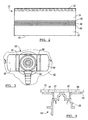
Figure 1 is an isometric view of a hollow tank formed in a mold and to which a component can be attached to an internal wall of the tank by the method; -
Figure 2 is an end view showing the layers of polymer material comprising a wall of the tank ofFigure 1 ; -
Figure 3 is a top view of a component to be welded to the tank wall; -
Figure 4 is a cross section of the component taken at plane 4-4 ofFigure 3 ; -
Figure 5 is an isometric view of the component held by a gripper and in position to be welded to the tank wall; and -
Figure 6 is an isometric top view of polymer film that may be secured to the wings before welding the component to the tank wall; and -
Figure 7 is an isometric view of a formed hollow body showing a gripper holding the component in position to be welded to the wall. -
Figure 1 illustrates ahollow body 10, which is preferably in the form of a hollow tank having a wall 12 (shown also inFigure 2 ) formed of multiple layers of plastic. Thetank 10 is usually and preferably formed by extruding layers of polymer through the orifice of an extrusion die. The extrusion is then closed, sealed and formed to shape in a mold, usually by applying blow-molding techniques. Twin sheet thermoforming is another technique used to manufacture these type tanks. A cross section taken at a plane perpendicular to the longitudinal axis of the tank may have any suitable shape. -
Figure 2 shows that thewall thickness 12 of thetank 10 includes a composite of various polymer layers including a relatively thinouter layer 32 of high density polyethylene (HDPE); a thick layer of scrap material 34, called regrind, sometimes incorporated into the multilayer wall thickness; a thin layer of adhesive 36, called a binder; a thin layer ofbarrier material 38, such as ethylene-vinyl alcohol (EVOH) copolymer; a second layer of adhesive 40; and a relatively thick,inner layer 42 of HDPE. Thebinder layers - When the
tank 10 is fully formed after processing in the mold, it may be used as a fuel tank in a motor vehicle. Thewall 12 is formed as a composite of multiple layers to prevent hydrocarbons emitted by fuel carried in the tank from passing through the thickness of thewall 12 and to provide flexural stiffness and strength. TheHDPE layer 42 provides theinner surface 44 of thetank 10 and is in contact with gasoline or another fluid contained in the tank. The wall of thetank 10 contains at least onebarrier layer 38 located within the multi-layer polymeric structure and surrounded on both sides by at least one layer of plastic having relatively insignificant barrier properties. The term "barrier layer" means a layer that has low permeation to gases and liquids.. It generally contains a barrier resin. Any known barrier resin may be present in the hollow body, provided that it is effective with respect to the fluids likely to be in contact with the container, particularly hydrocarbons. Non-limiting examples of possible resins for thebarrier layer 38 include polyamides or copolyamides and random copolymers of ethylene and of vinyl alcohol. A blend of different barrier resins is also possible. - The term "plastic" means any material containing at least one polymer. Thermoplastic polymers are preferred. The term "polymer" means both homopolymers and copolymers. Examples of such copolymers include, without limitation, random copolymers, copolymers from sequenced polymerization, block copolymers and graft copolymers. Thermoplastic polymers also include thermoplastic elastomers and blends thereof. In particular, the
tank 10 may contain polyolefins, thermoplastic polyesters, polyketones, polyamides and copolymers thereof. - A polymer often present in the wall of
tank 10 is polyethylene. The attachment method has produced excellent results with high density polyethylene (HDPE). A copolymer often used is the ethylene-vinyl alcohol (EVOH) copolymer. A blend of polymers or copolymers may also be used, as may a blend of polymeric substances with inorganic, organic and/or natural fillers. - After the
wall 12 oftank 10 is formed, anopening 50 is bored through thetank wall 12. In the case where the tank is a fuel tank, theopening 50 is for the later installation of a fuel delivery module (FDM) having a diameter of about 130 mm, although other diameters can be used. As shown inFigure 3 , acomponent 52, which can be handled by the associated welding apparatus, is inserted through theopening 50, moved to its proper position within thetank 10, and welded there to theinner surface 44 of the tank using a TTIR process. -
Figures 3 and 4 illustrate avalve component 52 formed with lateral weld features, such as wings orflanges inner surface 44 of thetank wall 12. The wings are spaced from thebody 58 byrecesses component 52 is concentrated at thewings wings target area 62 of theinner surface 44 of thetank wall 12 wherecomponent 52 will be welded to thetank 10. - Refer now to
Figures 5 and 6. Figure 5 illustrates anenergy source 64 of IR radiation or laser light, located integral tocomponent grippers 65, which engage thecomponent 52 outside thetank 10, carry the component through theaccess hole 50, and hold the component with thewings inner surface 44 of thewall 12 atarea 62 while a weld is produced. Energy fromsource 64 is directed throughwings inner surface 44 of tank wall 12 (seen best inFigure 2 ), or black or dark-colored areas ofthin film wings source 64 heats the top surface ofwings inner surface 44 oftank wall 12 atarea 62, thereby creating a weld or bond betweencomponent 52 andtank wall 12 inside the tank. -
Figure 7 illustrates thecomponent 52 engaged by thegripper 65, which is supported on a robotically manipulatedflexible arm 70 that entered thehollow body 10 throughhole 50. The arm moves thegripper 65 into its welding position where thewings inner surface 44 of thewall 12 at thetarget area 62. When the gripper and component are located as shown, energy fromsource 64 heats the top surface ofwings inner surface 44 oftank wall 12 atarea 62, thereby creating a weld or bond betweencomponent 52 andtank wall 12 inside the hollow body. - The
wings wings inner surface 44 of thewall 12 of HDPE. Preferably theHDPE layer 42 ofwall 12 is black or dark-colored. In this way, thearea 62 of the black HDPEinner surface 44 ofwall layer 42 immediately in contact with thewings wings inner surface 44 atarea 62 are heated. Energy radiated from theenergy source 64, which is located within thetank 10, continues to be directed onto thetarget area 62 until the temperatures of the mutually contacting surfaces of thewings inner surface 44 of thetank 10 increase sufficiently to weld thecomponent 52 to thetank wall 12. - Alternatively, the color of the
inner HDPE layer 42 of thetank wall 12 may be its natural color, i.e., uncolored by adding carbon, black colorant, or another dark colorant to the HDPE polymer. In this instance,thin films wings component 52 either during the molding process for the component or after the component is molded. In either case,films wings inner surface 44 attarget area 62. When energy transmitted by thesource 64 is absorbed at thefilms wings inner surface 44 of thetank 10 increase sufficiently to produce a weld betweencomponent 52 and theinner surface 44 of thetank 10. - The design of the welding feature can be adapted to the vapor control valve with either a separate piece which is attached to the vapor valve or as an integrally designed component of the valve. Placing the welding features 180 degrees apart and making them symmetrical allows the weld head to have design compliance flexibility to assist with the weld on an angled surface. The design optimizes the ability to grip the component and later release the component from the weld gripper apparatus while maintaining a narrow profile necessary for the restricted access inside the tank. The design permits the weld features to be placed on a surface which is able to pass through IR light to allow the application of force to the weld feature during the welding process in order to insure good molecular entanglement and hence a good weld. The feature also allows the valve manufacturer optimal opportunity to locate the nipple extension from the valve to which the internal vent line is attached. The weld area is slightly elevated from the rest of the component to insure un-melted material does not contact the inner tank surface during the welding operation, holding the component being welded away from the tank surface as melting occurs.
- Although the method is described with reference to a
fuel tank 10 for a motor vehicle, the method is applicable also to any hollow body. The term "hollow body" means any structure, which includes a wall surrounding at least one empty or hollow, concave part. Preferably, a hollow body denotes a closed structure such as a reservoir or tank suitable for containing liquids, gases, or mixtures of liquids/gases. A hollow body may have openings through its wall, which allowing communication with the external environment, and it may contain a fluid pump, level sensing equipment valves, and other components. - In accordance with the provisions of the patent statutes, the preferred embodiment has been described. However, it should be noted that the alternate embodiments can be practiced otherwise than as specifically illustrated and described.
Claims (17)
- A component to be welded to a surface of a polymer tank comprising:a body portion;a first wing secured to and extending laterally from the body, formed of polymer, and including a first surface that at least partially contacts the tank surface at the location of the weld; anda second wing secured to and extending laterally from the body and spaced from the first wing, formed of polymer, and including a second surface that at least partially contacts the tank surface at the location of the weld.
- The component of claim 1 wherein:the first surface has a first contour that at least partially conforms to a contour of the tank surface at the location of the weld; andthe second surface has a second contour that at least partially conforms to a contour of the tank surface at the location of the weld.
- The component of claim 1 further comprising:a first thin film of black polymer secured to the first surface; anda second thin film of black polymer secured to the second surface.
- The component of claim 1 wherein:the first wing and the second wing are formed of high density polyethylene.
- A method for welding a component to a tank, the method comprising the steps of:(a) forming the tank having a wall of multiple layers of polymer material with an opening in the wall, outer layers of polymer, and an inner layer of polymer having an inner surface whose color is dark relative to a natural color of the outer layers;(b) forming a component of polymer that includes a first wing having a first surface that at least partially contacts a corresponding tank surface at the location of the weld, and a second wing spaced from the first wing having a second surface that at least partially contacts a corresponding tank surface at the location of the weld.(c) using the opening to install the component in the tank such that the first and second surfaces contact the corresponding inner surface of the tank at the weld;(d) transmitting energy through the component onto an area of a surface of the tank wall where the mounting surface contacts the inner surface; and(e) using said transmitted energy to produce a weld between the component mounting surface and the tank inner wall.
- The method of claim 5 wherein a color an inner surface of the inner layer is black.
- The method of claim 5 wherein step (d) further comprises transmitting energy from a source of IR radiation onto the area.
- The method of claim 5 wherein step (d) further comprises transmitting energy from a source of laser light onto the area.
- The method of claim 5 wherein step (a) further comprises:forming the tank with an inner surface whose color is dark relative to the natural color of the polymer of each of the outer layers and a natural color of the inner layer other than the inner surface of the inner layer.
- The method of claim 5 wherein step (a) further comprises:locating outer layers of HDPE polymer, regrind polymer, a barrier layer and adhesive layers external to the inner layer.
- A method for securing a component to a tank, the method comprising the steps of:(a) forming the tank having a wall of multiple layers of polymer material with an opening in the wall, outer layers of polymer, and an inner layer of polymer having an inner surface;(b) securing to the inner surface a film of polymer whose color is dark relative to a natural color of the polymer;(c) forming the component with a mounting surface formed of polymer;(d) using the opening to install the component in the tank such that the mounting surface contacts the film;(e) transmitting energy onto an area of an internal surface of the tank wall where the mounting surface contacts the film; and(f) using said transmitted energy to produce a weld between the mounting surface and the tube wall.
- The method of claim 11 wherein a color of the film is black.
- The method of claim 11 wherein a color of the inner layer is black.
- The method of claim 11 wherein step (e) further comprises transmitting energy from a source of IR radiation onto the area.
- The method of claim 11 wherein step (e) further comprises transmitting energy from a source of laser light onto the area.
- The method of claim 11 wherein step (a) further comprises:forming the tank with an inner surface whose color is dark relative to a natural color of the polymer of each of the outer layers and a natural color of the inner layer.
- The method of claim 11 wherein step (a) further comprises:locating outer layers of HDPE polymer, regrind polymer, a barrier layer and adhesive layers external to the inner layer.
Applications Claiming Priority (1)
| Application Number | Priority Date | Filing Date | Title |
|---|---|---|---|
| US11/704,643 US7829819B2 (en) | 2007-02-08 | 2007-02-08 | Attaching a component to an internal surface of a tank formed of polymer |
Publications (3)
| Publication Number | Publication Date |
|---|---|
| EP1955887A2 true EP1955887A2 (en) | 2008-08-13 |
| EP1955887A3 EP1955887A3 (en) | 2010-04-14 |
| EP1955887B1 EP1955887B1 (en) | 2011-09-07 |
Family
ID=39358034
Family Applications (1)
| Application Number | Title | Priority Date | Filing Date |
|---|---|---|---|
| EP20080250458 Expired - Fee Related EP1955887B1 (en) | 2007-02-08 | 2008-02-07 | Fuel tank with attached component and method of making same |
Country Status (3)
| Country | Link |
|---|---|
| US (1) | US7829819B2 (en) |
| EP (1) | EP1955887B1 (en) |
| CN (1) | CN101269717B (en) |
Cited By (42)
| Publication number | Priority date | Publication date | Assignee | Title |
|---|---|---|---|---|
| EP2340955A1 (en) * | 2009-12-24 | 2011-07-06 | Honda Motor Co., Ltd. | Plastic fuel tank |
| US8318277B2 (en) | 2009-12-24 | 2012-11-27 | Honda Motor Co., Ltd. | Plastic fuel tank |
| WO2014146911A1 (en) * | 2013-03-22 | 2014-09-25 | Kautex Textron Gmbh & Co. Kg | Method for manufacturing a fuel tank and fuel tank |
| WO2016103033A3 (en) * | 2014-12-22 | 2016-09-15 | Smith & Nephew Plc | Negative pressure wound therapy apparatus and methods |
| FR3056941A1 (en) * | 2016-09-30 | 2018-04-06 | Plastic Omnium Advanced Innovation & Res | METHOD FOR FIXING A COMPONENT TO A VEHICLE TANK |
| US10159604B2 (en) | 2010-04-27 | 2018-12-25 | Smith & Nephew Plc | Wound dressing and method of use |
| US10188555B2 (en) | 2008-03-13 | 2019-01-29 | Smith & Nephew, Inc. | Shear resistant wound dressing for use in vacuum wound therapy |
| US10201644B2 (en) | 2005-09-07 | 2019-02-12 | Smith & Nephew, Inc. | Self contained wound dressing with micropump |
| US10207035B2 (en) | 2004-05-21 | 2019-02-19 | Smith & Nephew, Inc. | Flexible reduced pressure treatment appliance |
| US10231875B2 (en) | 2007-11-21 | 2019-03-19 | Smith & Nephew Plc | Wound dressing |
| US10231878B2 (en) | 2011-05-17 | 2019-03-19 | Smith & Nephew Plc | Tissue healing |
| EP3459709A1 (en) * | 2017-09-26 | 2019-03-27 | Magna Steyr Fuel Systems GesmbH | Plastic tank |
| US10258779B2 (en) | 2008-09-05 | 2019-04-16 | Smith & Nephew, Inc. | Three-dimensional porous film contact layer with improved wound healing |
| US10278869B2 (en) | 2002-10-28 | 2019-05-07 | Smith & Nephew Plc | Apparatus for aspirating, irrigating and cleansing wounds |
| US10363346B2 (en) | 2004-04-05 | 2019-07-30 | Smith & Nephew, Inc. | Flexible reduced pressure treatment appliance |
| US10391212B2 (en) | 2006-05-11 | 2019-08-27 | Smith & Nephew, Inc. | Device and method for wound therapy |
| US10426875B2 (en) | 2003-10-28 | 2019-10-01 | Smith & Nephew Plc | Wound cleansing apparatus in-situ |
| US10493184B2 (en) | 2013-03-15 | 2019-12-03 | Smith & Nephew Plc | Wound dressing and method of treatment |
| US10507141B2 (en) | 2012-05-23 | 2019-12-17 | Smith & Nephew Plc | Apparatuses and methods for negative pressure wound therapy |
| US10537657B2 (en) | 2010-11-25 | 2020-01-21 | Smith & Nephew Plc | Composition I-II and products and uses thereof |
| US10548776B2 (en) | 2006-09-26 | 2020-02-04 | Smith & Nephew, Inc. | Wound dressing |
| US10610414B2 (en) | 2014-06-18 | 2020-04-07 | Smith & Nephew Plc | Wound dressing and method of treatment |
| US10695226B2 (en) | 2013-03-15 | 2020-06-30 | Smith & Nephew Plc | Wound dressing and method of treatment |
| US10842919B2 (en) | 2004-04-05 | 2020-11-24 | Smith & Nephew, Inc. | Reduced pressure treatment system |
| US10881764B2 (en) | 2012-03-20 | 2021-01-05 | Smith & Nephew Plc | Controlling operation of a reduced pressure therapy system based on dynamic duty cycle threshold determination |
| USD914887S1 (en) | 2012-08-01 | 2021-03-30 | Smith & Nephew Plc | Wound dressing |
| US11045598B2 (en) | 2007-11-21 | 2021-06-29 | Smith & Nephew Plc | Vacuum assisted wound dressing |
| US11090196B2 (en) | 2015-12-30 | 2021-08-17 | Smith & Nephew Plc | Absorbent negative pressure wound therapy dressing |
| US11110010B2 (en) | 2007-11-21 | 2021-09-07 | Smith & Nephew Plc | Wound dressing |
| US11344663B2 (en) | 2007-11-21 | 2022-05-31 | T.J.Smith And Nephew, Limited | Suction device and dressing |
| US11364150B2 (en) | 2015-12-30 | 2022-06-21 | Smith & Nephew Plc | Negative pressure wound therapy apparatus |
| US11389582B2 (en) | 2017-09-29 | 2022-07-19 | T.J. Smith And Nephew, Limited | Negative pressure wound therapy apparatus with removable panels |
| US11471333B2 (en) | 2017-06-14 | 2022-10-18 | T.J.Smith And Nephew, Limited | Negative pressure wound therapy apparatus |
| USD977624S1 (en) | 2016-02-29 | 2023-02-07 | Smith & Nephew Plc | Portable negative pressure apparatus |
| US11638666B2 (en) | 2011-11-25 | 2023-05-02 | Smith & Nephew Plc | Composition, apparatus, kit and method and uses thereof |
| US11638663B2 (en) | 2008-03-13 | 2023-05-02 | Smith & Nephew, Inc. | Vacuum wound therapy wound dressing with variable performance zones |
| US11771820B2 (en) | 2016-03-04 | 2023-10-03 | Smith & Nephew Plc | Negative pressure wound therapy apparatus for post breast surgery wounds |
| US11806217B2 (en) | 2016-12-12 | 2023-11-07 | Smith & Nephew Plc | Wound dressing |
| US11819386B2 (en) | 2018-07-12 | 2023-11-21 | T.J.Smith And Nephew, Limited | Apparatuses and methods for negative pressure wound therapy |
| US11896754B2 (en) | 2005-09-07 | 2024-02-13 | Smith & Nephew, Inc. | Wound dressing with vacuum reservoir |
| US11931226B2 (en) | 2013-03-15 | 2024-03-19 | Smith & Nephew Plc | Wound dressing sealant and use thereof |
| US11938231B2 (en) | 2010-11-25 | 2024-03-26 | Smith & Nephew Plc | Compositions I-I and products and uses thereof |
Families Citing this family (11)
| Publication number | Priority date | Publication date | Assignee | Title |
|---|---|---|---|---|
| FR2934806A1 (en) * | 2008-08-07 | 2010-02-12 | Inergy Automotive Systems Res | METHOD FOR ATTACHING AN ACCESSORY IN A HOLLOW BODY OF PLASTIC MATERIAL |
| US8147599B2 (en) | 2009-02-17 | 2012-04-03 | Mcalister Technologies, Llc | Apparatuses and methods for storing and/or filtering a substance |
| JP4928595B2 (en) * | 2009-10-19 | 2012-05-09 | 本田技研工業株式会社 | Washer tank mounting body structure |
| FR2952142B1 (en) * | 2009-10-29 | 2016-01-22 | Inergy Automotive Systems Res | HOLLOW BODY COMPRISING AN ACCESSORY MODULE FIXED ON ITS WALL, AND MODULE ADAPTED FOR SUCH A HOLLOW BODY |
| US9314719B2 (en) | 2011-08-12 | 2016-04-19 | Mcalister Technologies, Llc | Filter having spiral-shaped distributor channels |
| WO2014145882A1 (en) | 2013-03-15 | 2014-09-18 | Mcalister Technologies, Llc | Methods of manufacture of engineered materials and devices |
| WO2014194124A1 (en) * | 2013-05-29 | 2014-12-04 | Mcalister Technologies, Llc | Methods for fuel tank recycling and net hydrogen fuel and carbon goods production along with associated apparatus and systems |
| EP3178687A1 (en) | 2015-12-08 | 2017-06-14 | Plastic Omnium Advanced Innovation and Research | Valve apparatus for venting a liquid tank |
| US10794523B2 (en) * | 2015-12-14 | 2020-10-06 | Wilmarc Holdings, Llc | Laser induced sealing of concentrically layered materials |
| EP3184341A1 (en) | 2015-12-22 | 2017-06-28 | Plastic Omnium Advanced Innovation and Research | Valve apparatus with a weight control system |
| EP3225820A1 (en) | 2016-03-29 | 2017-10-04 | Plastic Omnium Advanced Innovation and Research | Vehicle tank equipped with a liquid level sensing system |
Citations (4)
| Publication number | Priority date | Publication date | Assignee | Title |
|---|---|---|---|---|
| WO2002014041A2 (en) * | 2000-08-11 | 2002-02-21 | Visteon Global Technologies, Inc. | Adapter for welding objects to plastic |
| EP1310715A1 (en) * | 2001-11-13 | 2003-05-14 | Eaton Corporation | Attachment of fuel vapor vent valve to the inside of a fuel tank |
| US20050115054A1 (en) * | 2003-12-02 | 2005-06-02 | Brandner Brian W. | Fuel system component and method of manufacture |
| US20060283543A1 (en) * | 2005-06-20 | 2006-12-21 | Masanori Kubota | Pseudo-transmission method of forming and joining articles |
Family Cites Families (10)
| Publication number | Priority date | Publication date | Assignee | Title |
|---|---|---|---|---|
| US6035883A (en) * | 1998-03-13 | 2000-03-14 | Eaton Corporation | Weldable vapor vent valve for fuel tanks |
| CN1200805C (en) * | 2000-08-04 | 2005-05-11 | 弗利亚特克公司 | Device for connecting fusible plastic components |
| DE10054874C2 (en) * | 2000-11-06 | 2003-05-08 | Sig Kautex Gmbh & Co Kg | Fuel tank |
| US6810913B2 (en) * | 2002-04-26 | 2004-11-02 | Visteon Global Technologies, Inc. | Internal fuel vapor valve |
| US6877627B2 (en) * | 2003-01-28 | 2005-04-12 | Ti Group Automotive Systems, L.L.C. | Fuel tank |
| US7565986B2 (en) * | 2003-12-02 | 2009-07-28 | Ti Group Automotive Systems, L.L.C. | Fuel system component and method of manufacture |
| US20050127078A1 (en) * | 2003-12-11 | 2005-06-16 | Vorenkamp Erich J. | Fuel tank assembly and method of assembly |
| US8381928B2 (en) * | 2004-06-04 | 2013-02-26 | Ti Group Automotive Systems, L.L.C. | Multilayer fuel tank with a seam having an overlay for reducing vapor permeation |
| JP2006151365A (en) * | 2004-10-26 | 2006-06-15 | Tokai Rubber Ind Ltd | Joint part for resin fuel tank and manufacturing method thereof |
| US7378624B2 (en) * | 2005-02-11 | 2008-05-27 | Denso International America, Inc. | Method of welding a component inside a hollow vessel |
-
2007
- 2007-02-08 US US11/704,643 patent/US7829819B2/en active Active
-
2008
- 2008-02-02 CN CN200810009447XA patent/CN101269717B/en active Active
- 2008-02-07 EP EP20080250458 patent/EP1955887B1/en not_active Expired - Fee Related
Patent Citations (4)
| Publication number | Priority date | Publication date | Assignee | Title |
|---|---|---|---|---|
| WO2002014041A2 (en) * | 2000-08-11 | 2002-02-21 | Visteon Global Technologies, Inc. | Adapter for welding objects to plastic |
| EP1310715A1 (en) * | 2001-11-13 | 2003-05-14 | Eaton Corporation | Attachment of fuel vapor vent valve to the inside of a fuel tank |
| US20050115054A1 (en) * | 2003-12-02 | 2005-06-02 | Brandner Brian W. | Fuel system component and method of manufacture |
| US20060283543A1 (en) * | 2005-06-20 | 2006-12-21 | Masanori Kubota | Pseudo-transmission method of forming and joining articles |
Cited By (79)
| Publication number | Priority date | Publication date | Assignee | Title |
|---|---|---|---|---|
| US10278869B2 (en) | 2002-10-28 | 2019-05-07 | Smith & Nephew Plc | Apparatus for aspirating, irrigating and cleansing wounds |
| US11857746B2 (en) | 2003-10-28 | 2024-01-02 | Smith & Nephew Plc | Wound cleansing apparatus in-situ |
| US10758651B2 (en) | 2003-10-28 | 2020-09-01 | Smith & Nephew Plc | Wound cleansing apparatus in-situ |
| US10426875B2 (en) | 2003-10-28 | 2019-10-01 | Smith & Nephew Plc | Wound cleansing apparatus in-situ |
| US11730874B2 (en) | 2004-04-05 | 2023-08-22 | Smith & Nephew, Inc. | Reduced pressure treatment appliance |
| US10842919B2 (en) | 2004-04-05 | 2020-11-24 | Smith & Nephew, Inc. | Reduced pressure treatment system |
| US10363346B2 (en) | 2004-04-05 | 2019-07-30 | Smith & Nephew, Inc. | Flexible reduced pressure treatment appliance |
| US10207035B2 (en) | 2004-05-21 | 2019-02-19 | Smith & Nephew, Inc. | Flexible reduced pressure treatment appliance |
| US10201644B2 (en) | 2005-09-07 | 2019-02-12 | Smith & Nephew, Inc. | Self contained wound dressing with micropump |
| US11896754B2 (en) | 2005-09-07 | 2024-02-13 | Smith & Nephew, Inc. | Wound dressing with vacuum reservoir |
| US11737925B2 (en) | 2005-09-07 | 2023-08-29 | Smith & Nephew, Inc. | Self contained wound dressing with micropump |
| US11278658B2 (en) | 2005-09-07 | 2022-03-22 | Smith & Nephew, Inc. | Self contained wound dressing with micropump |
| US11813394B2 (en) | 2006-05-11 | 2023-11-14 | Smith & Nephew, Inc. | Device and method for wound therapy |
| US10744242B2 (en) | 2006-05-11 | 2020-08-18 | Smith & Nephew, Inc. | Device and method for wound therapy |
| US10391212B2 (en) | 2006-05-11 | 2019-08-27 | Smith & Nephew, Inc. | Device and method for wound therapy |
| US11517656B2 (en) | 2006-05-11 | 2022-12-06 | Smith & Nephew, Inc. | Device and method for wound therapy |
| US11801165B2 (en) | 2006-09-26 | 2023-10-31 | Smith & Nephew, Inc. | Wound dressing |
| US11701263B2 (en) | 2006-09-26 | 2023-07-18 | Smith & Nephew, Inc. | Wound dressing |
| US10548776B2 (en) | 2006-09-26 | 2020-02-04 | Smith & Nephew, Inc. | Wound dressing |
| US11083628B2 (en) | 2006-09-26 | 2021-08-10 | Smith & Nephew, Inc. | Wound dressing |
| US10231875B2 (en) | 2007-11-21 | 2019-03-19 | Smith & Nephew Plc | Wound dressing |
| US11179276B2 (en) | 2007-11-21 | 2021-11-23 | Smith & Nephew Plc | Wound dressing |
| US11766512B2 (en) | 2007-11-21 | 2023-09-26 | T.J.Smith And Nephew, Limited | Suction device and dressing |
| US10555839B2 (en) | 2007-11-21 | 2020-02-11 | Smith & Nephew Plc | Wound dressing |
| US11344663B2 (en) | 2007-11-21 | 2022-05-31 | T.J.Smith And Nephew, Limited | Suction device and dressing |
| US11364151B2 (en) | 2007-11-21 | 2022-06-21 | Smith & Nephew Plc | Wound dressing |
| US11701266B2 (en) | 2007-11-21 | 2023-07-18 | Smith & Nephew Plc | Vacuum assisted wound dressing |
| US11045598B2 (en) | 2007-11-21 | 2021-06-29 | Smith & Nephew Plc | Vacuum assisted wound dressing |
| US10744041B2 (en) | 2007-11-21 | 2020-08-18 | Smith & Nephew Plc | Wound dressing |
| US11351064B2 (en) | 2007-11-21 | 2022-06-07 | Smith & Nephew Plc | Wound dressing |
| US11110010B2 (en) | 2007-11-21 | 2021-09-07 | Smith & Nephew Plc | Wound dressing |
| US11129751B2 (en) | 2007-11-21 | 2021-09-28 | Smith & Nephew Plc | Wound dressing |
| US11638663B2 (en) | 2008-03-13 | 2023-05-02 | Smith & Nephew, Inc. | Vacuum wound therapy wound dressing with variable performance zones |
| US10188555B2 (en) | 2008-03-13 | 2019-01-29 | Smith & Nephew, Inc. | Shear resistant wound dressing for use in vacuum wound therapy |
| US11523943B2 (en) | 2008-03-13 | 2022-12-13 | Smith & Nephew, Inc. | Shear resistant wound dressing for use in vacuum wound therapy |
| US10258779B2 (en) | 2008-09-05 | 2019-04-16 | Smith & Nephew, Inc. | Three-dimensional porous film contact layer with improved wound healing |
| EP2340955A1 (en) * | 2009-12-24 | 2011-07-06 | Honda Motor Co., Ltd. | Plastic fuel tank |
| US8765242B2 (en) | 2009-12-24 | 2014-07-01 | Honda Motor Co., Ltd. | Plastic fuel tank |
| US8318277B2 (en) | 2009-12-24 | 2012-11-27 | Honda Motor Co., Ltd. | Plastic fuel tank |
| US11058587B2 (en) | 2010-04-27 | 2021-07-13 | Smith & Nephew Plc | Wound dressing and method of use |
| US11090195B2 (en) | 2010-04-27 | 2021-08-17 | Smith & Nephew Plc | Wound dressing and method of use |
| US10159604B2 (en) | 2010-04-27 | 2018-12-25 | Smith & Nephew Plc | Wound dressing and method of use |
| US11938231B2 (en) | 2010-11-25 | 2024-03-26 | Smith & Nephew Plc | Compositions I-I and products and uses thereof |
| US10537657B2 (en) | 2010-11-25 | 2020-01-21 | Smith & Nephew Plc | Composition I-II and products and uses thereof |
| US11730876B2 (en) | 2010-11-25 | 2023-08-22 | Smith & Nephew Plc | Composition I-II and products and uses thereof |
| US10231878B2 (en) | 2011-05-17 | 2019-03-19 | Smith & Nephew Plc | Tissue healing |
| US11246757B2 (en) | 2011-05-17 | 2022-02-15 | Smith & Nephew Plc | Tissue healing |
| US11638666B2 (en) | 2011-11-25 | 2023-05-02 | Smith & Nephew Plc | Composition, apparatus, kit and method and uses thereof |
| US11730877B2 (en) | 2012-03-20 | 2023-08-22 | Smith & Nephew Plc | Controlling operation of a reduced pressure therapy system based on dynamic duty cycle threshold determination |
| US10881764B2 (en) | 2012-03-20 | 2021-01-05 | Smith & Nephew Plc | Controlling operation of a reduced pressure therapy system based on dynamic duty cycle threshold determination |
| US10507141B2 (en) | 2012-05-23 | 2019-12-17 | Smith & Nephew Plc | Apparatuses and methods for negative pressure wound therapy |
| US11590029B2 (en) | 2012-05-23 | 2023-02-28 | Smith & Nephew Plc | Apparatuses and methods for negative pressure wound therapy |
| USD914887S1 (en) | 2012-08-01 | 2021-03-30 | Smith & Nephew Plc | Wound dressing |
| US10695226B2 (en) | 2013-03-15 | 2020-06-30 | Smith & Nephew Plc | Wound dressing and method of treatment |
| US11771796B2 (en) | 2013-03-15 | 2023-10-03 | Smith & Nephew Plc | Wound dressing and method of treatment |
| US11931226B2 (en) | 2013-03-15 | 2024-03-19 | Smith & Nephew Plc | Wound dressing sealant and use thereof |
| US10493184B2 (en) | 2013-03-15 | 2019-12-03 | Smith & Nephew Plc | Wound dressing and method of treatment |
| US9987797B2 (en) | 2013-03-22 | 2018-06-05 | Kautex Textron Gmbh & Co. Kg | Method for manufacturing a fuel tank and fuel tank |
| WO2014146911A1 (en) * | 2013-03-22 | 2014-09-25 | Kautex Textron Gmbh & Co. Kg | Method for manufacturing a fuel tank and fuel tank |
| US11596552B2 (en) | 2014-06-18 | 2023-03-07 | Smith & Nephew Plc | Wound dressing and method of treatment |
| US10610414B2 (en) | 2014-06-18 | 2020-04-07 | Smith & Nephew Plc | Wound dressing and method of treatment |
| US11654228B2 (en) | 2014-12-22 | 2023-05-23 | Smith & Nephew Plc | Status indication for negative pressure wound therapy |
| WO2016103033A3 (en) * | 2014-12-22 | 2016-09-15 | Smith & Nephew Plc | Negative pressure wound therapy apparatus and methods |
| US10682446B2 (en) | 2014-12-22 | 2020-06-16 | Smith & Nephew Plc | Dressing status detection for negative pressure wound therapy |
| US10737002B2 (en) | 2014-12-22 | 2020-08-11 | Smith & Nephew Plc | Pressure sampling systems and methods for negative pressure wound therapy |
| US10780202B2 (en) | 2014-12-22 | 2020-09-22 | Smith & Nephew Plc | Noise reduction for negative pressure wound therapy apparatuses |
| US10973965B2 (en) | 2014-12-22 | 2021-04-13 | Smith & Nephew Plc | Systems and methods of calibrating operating parameters of negative pressure wound therapy apparatuses |
| US11364150B2 (en) | 2015-12-30 | 2022-06-21 | Smith & Nephew Plc | Negative pressure wound therapy apparatus |
| US11766365B2 (en) | 2015-12-30 | 2023-09-26 | Smith & Nephew Plc | Negative pressure wound therapy apparatus |
| US11090196B2 (en) | 2015-12-30 | 2021-08-17 | Smith & Nephew Plc | Absorbent negative pressure wound therapy dressing |
| USD977624S1 (en) | 2016-02-29 | 2023-02-07 | Smith & Nephew Plc | Portable negative pressure apparatus |
| USD985755S1 (en) | 2016-02-29 | 2023-05-09 | Smith & Nephew Plc | Portable negative pressure apparatus |
| US11771820B2 (en) | 2016-03-04 | 2023-10-03 | Smith & Nephew Plc | Negative pressure wound therapy apparatus for post breast surgery wounds |
| FR3056941A1 (en) * | 2016-09-30 | 2018-04-06 | Plastic Omnium Advanced Innovation & Res | METHOD FOR FIXING A COMPONENT TO A VEHICLE TANK |
| US11806217B2 (en) | 2016-12-12 | 2023-11-07 | Smith & Nephew Plc | Wound dressing |
| US11471333B2 (en) | 2017-06-14 | 2022-10-18 | T.J.Smith And Nephew, Limited | Negative pressure wound therapy apparatus |
| EP3459709A1 (en) * | 2017-09-26 | 2019-03-27 | Magna Steyr Fuel Systems GesmbH | Plastic tank |
| US11389582B2 (en) | 2017-09-29 | 2022-07-19 | T.J. Smith And Nephew, Limited | Negative pressure wound therapy apparatus with removable panels |
| US11819386B2 (en) | 2018-07-12 | 2023-11-21 | T.J.Smith And Nephew, Limited | Apparatuses and methods for negative pressure wound therapy |
Also Published As
| Publication number | Publication date |
|---|---|
| CN101269717A (en) | 2008-09-24 |
| EP1955887A3 (en) | 2010-04-14 |
| US7829819B2 (en) | 2010-11-09 |
| EP1955887B1 (en) | 2011-09-07 |
| US20080190943A1 (en) | 2008-08-14 |
| CN101269717B (en) | 2011-09-28 |
Similar Documents
| Publication | Publication Date | Title |
|---|---|---|
| EP1955887B1 (en) | Fuel tank with attached component and method of making same | |
| EP2167305B1 (en) | Method for fastening an accessory to a plastic fuel tank | |
| KR102153866B1 (en) | Automotive liquid container and method for manufacturing liquid container | |
| US8122604B2 (en) | Method for fastening an accessory to a plastic fuel tank | |
| US9394157B2 (en) | Fueling device and manufacturing method of a fueling device | |
| US20030124281A1 (en) | Liquid-or vapor-conducting system with a jointing zone made from a coextruded multilayer composite | |
| US8631556B2 (en) | Process for manufacturing a plastic fuel tank equipped with a pump | |
| US20150239198A1 (en) | Attaching structure of insert member to blow molded article | |
| US7513379B2 (en) | Fuel tank and method for making same | |
| EP3328672B1 (en) | Liquid vehicle tank comprising a fastened component | |
| US7171749B2 (en) | Tube connector for fuel tank | |
| WO2016050794A1 (en) | Method for welding a heat shield during manufacturing of a vehicle component | |
| WO2007122168A1 (en) | Method for manufacturing a plastic fuel tank | |
| US11724591B2 (en) | Liquid container and method for manufacturing a liquid container | |
| JP2014046676A (en) | Attachment structure for insert member of blow molding item | |
| KR20040050921A (en) | System and method for sealing a tank opening | |
| WO2000043230A1 (en) | Plastic fuel tank with pipe nipple | |
| JP2009132200A (en) | Weld joint for fuel tank | |
| JP3529727B2 (en) | Structure of the joint part of the child part to the fuel tank made of synthetic resin | |
| JP2016141055A (en) | Component welding apparatus | |
| JP6788939B2 (en) | How to install the filler pipe | |
| JP2017024275A (en) | Fusion-bonding apparatus for fuel tank components | |
| JP2014043064A (en) | Structure for fitting an insert member to blow molded product | |
| WO2007122185A1 (en) | Method of manufacturing a fuel tank |
Legal Events
| Date | Code | Title | Description |
|---|---|---|---|
| PUAI | Public reference made under article 153(3) epc to a published international application that has entered the european phase |
Free format text: ORIGINAL CODE: 0009012 |
|
| AK | Designated contracting states |
Kind code of ref document: A2 Designated state(s): AT BE BG CH CY CZ DE DK EE ES FI FR GB GR HR HU IE IS IT LI LT LU LV MC MT NL NO PL PT RO SE SI SK TR |
|
| AX | Request for extension of the european patent |
Extension state: AL BA MK RS |
|
| PUAL | Search report despatched |
Free format text: ORIGINAL CODE: 0009013 |
|
| AK | Designated contracting states |
Kind code of ref document: A3 Designated state(s): AT BE BG CH CY CZ DE DK EE ES FI FR GB GR HR HU IE IS IT LI LT LU LV MC MT NL NO PL PT RO SE SI SK TR |
|
| AX | Request for extension of the european patent |
Extension state: AL BA MK RS |
|
| 17P | Request for examination filed |
Effective date: 20101006 |
|
| AKX | Designation fees paid |
Designated state(s): DE FR GB |
|
| GRAP | Despatch of communication of intention to grant a patent |
Free format text: ORIGINAL CODE: EPIDOSNIGR1 |
|
| RIC1 | Information provided on ipc code assigned before grant |
Ipc: F17C 3/00 20060101ALN20110217BHEP Ipc: B65D 6/00 20060101ALN20110217BHEP Ipc: B29C 65/16 20060101ALN20110217BHEP Ipc: F16K 24/00 20060101ALN20110217BHEP Ipc: B23K 9/00 20060101ALN20110217BHEP Ipc: F16L 9/00 20060101ALN20110217BHEP Ipc: B65D 25/00 20060101ALN20110217BHEP Ipc: B60K 15/03 20060101AFI20110217BHEP Ipc: F17C 13/00 20060101ALN20110217BHEP Ipc: B29C 65/14 20060101ALN20110217BHEP Ipc: B65D 65/40 20060101ALN20110217BHEP |
|
| RTI1 | Title (correction) |
Free format text: FUEL TANK WITH ATTACHED COMPONENT AND METHOD OF MAKING SAME |
|
| GRAS | Grant fee paid |
Free format text: ORIGINAL CODE: EPIDOSNIGR3 |
|
| GRAA | (expected) grant |
Free format text: ORIGINAL CODE: 0009210 |
|
| REG | Reference to a national code |
Ref country code: GB Ref legal event code: FG4D |
|
| REG | Reference to a national code |
Ref country code: DE Ref legal event code: R096 Ref document number: 602008009515 Country of ref document: DE Effective date: 20111103 |
|
| RAP2 | Party data changed (patent owner data changed or rights of a patent transferred) |
Owner name: INERGY AUTOMOTIVE SYSTEMS RESEARCH (SA) |
|
| REG | Reference to a national code |
Ref country code: DE Ref legal event code: R081 Ref document number: 602008009515 Country of ref document: DE Owner name: INERGY AUTOMOTIVE SYSTEMS RESEARCH (SA), BE Free format text: FORMER OWNER: AUTOMOTIVE COMPONENTS HOLDINGS, LLC, DEARBORN, US Effective date: 20111208 Ref country code: DE Ref legal event code: R081 Ref document number: 602008009515 Country of ref document: DE Owner name: INERGY AUTOMOTIVE SYSTEMS RESEARCH (SA), BE Free format text: FORMER OWNER: AUTOMOTIVE COMPONENTS HOLDINGS, LLC, DEARBORN, MICH., US Effective date: 20111208 |
|
| PLBE | No opposition filed within time limit |
Free format text: ORIGINAL CODE: 0009261 |
|
| STAA | Information on the status of an ep patent application or granted ep patent |
Free format text: STATUS: NO OPPOSITION FILED WITHIN TIME LIMIT |
|
| 26N | No opposition filed |
Effective date: 20120611 |
|
| REG | Reference to a national code |
Ref country code: DE Ref legal event code: R097 Ref document number: 602008009515 Country of ref document: DE Effective date: 20120611 |
|
| GBPC | Gb: european patent ceased through non-payment of renewal fee |
Effective date: 20120207 |
|
| PG25 | Lapsed in a contracting state [announced via postgrant information from national office to epo] |
Ref country code: GB Free format text: LAPSE BECAUSE OF NON-PAYMENT OF DUE FEES Effective date: 20120207 |
|
| PGFP | Annual fee paid to national office [announced via postgrant information from national office to epo] |
Ref country code: DE Payment date: 20140227 Year of fee payment: 7 |
|
| PGFP | Annual fee paid to national office [announced via postgrant information from national office to epo] |
Ref country code: FR Payment date: 20140224 Year of fee payment: 7 |
|
| REG | Reference to a national code |
Ref country code: DE Ref legal event code: R119 Ref document number: 602008009515 Country of ref document: DE |
|
| REG | Reference to a national code |
Ref country code: FR Ref legal event code: ST Effective date: 20151030 |
|
| PG25 | Lapsed in a contracting state [announced via postgrant information from national office to epo] |
Ref country code: DE Free format text: LAPSE BECAUSE OF NON-PAYMENT OF DUE FEES Effective date: 20150901 |
|
| PG25 | Lapsed in a contracting state [announced via postgrant information from national office to epo] |
Ref country code: FR Free format text: LAPSE BECAUSE OF NON-PAYMENT OF DUE FEES Effective date: 20150302 |