EP3178687A1 - Valve apparatus for venting a liquid tank - Google Patents
Valve apparatus for venting a liquid tank Download PDFInfo
- Publication number
- EP3178687A1 EP3178687A1 EP15198453.1A EP15198453A EP3178687A1 EP 3178687 A1 EP3178687 A1 EP 3178687A1 EP 15198453 A EP15198453 A EP 15198453A EP 3178687 A1 EP3178687 A1 EP 3178687A1
- Authority
- EP
- European Patent Office
- Prior art keywords
- float
- valve apparatus
- main
- area
- main chamber
- Prior art date
- Legal status (The legal status is an assumption and is not a legal conclusion. Google has not performed a legal analysis and makes no representation as to the accuracy of the status listed.)
- Withdrawn
Links
Images

Classifications
-
- B—PERFORMING OPERATIONS; TRANSPORTING
- B60—VEHICLES IN GENERAL
- B60K—ARRANGEMENT OR MOUNTING OF PROPULSION UNITS OR OF TRANSMISSIONS IN VEHICLES; ARRANGEMENT OR MOUNTING OF PLURAL DIVERSE PRIME-MOVERS IN VEHICLES; AUXILIARY DRIVES FOR VEHICLES; INSTRUMENTATION OR DASHBOARDS FOR VEHICLES; ARRANGEMENTS IN CONNECTION WITH COOLING, AIR INTAKE, GAS EXHAUST OR FUEL SUPPLY OF PROPULSION UNITS IN VEHICLES
- B60K15/00—Arrangement in connection with fuel supply of combustion engines or other fuel consuming energy converters, e.g. fuel cells; Mounting or construction of fuel tanks
- B60K15/03—Fuel tanks
- B60K15/035—Fuel tanks characterised by venting means
-
- F—MECHANICAL ENGINEERING; LIGHTING; HEATING; WEAPONS; BLASTING
- F16—ENGINEERING ELEMENTS AND UNITS; GENERAL MEASURES FOR PRODUCING AND MAINTAINING EFFECTIVE FUNCTIONING OF MACHINES OR INSTALLATIONS; THERMAL INSULATION IN GENERAL
- F16K—VALVES; TAPS; COCKS; ACTUATING-FLOATS; DEVICES FOR VENTING OR AERATING
- F16K24/00—Devices, e.g. valves, for venting or aerating enclosures
- F16K24/04—Devices, e.g. valves, for venting or aerating enclosures for venting only
- F16K24/042—Devices, e.g. valves, for venting or aerating enclosures for venting only actuated by a float
-
- B—PERFORMING OPERATIONS; TRANSPORTING
- B60—VEHICLES IN GENERAL
- B60K—ARRANGEMENT OR MOUNTING OF PROPULSION UNITS OR OF TRANSMISSIONS IN VEHICLES; ARRANGEMENT OR MOUNTING OF PLURAL DIVERSE PRIME-MOVERS IN VEHICLES; AUXILIARY DRIVES FOR VEHICLES; INSTRUMENTATION OR DASHBOARDS FOR VEHICLES; ARRANGEMENTS IN CONNECTION WITH COOLING, AIR INTAKE, GAS EXHAUST OR FUEL SUPPLY OF PROPULSION UNITS IN VEHICLES
- B60K15/00—Arrangement in connection with fuel supply of combustion engines or other fuel consuming energy converters, e.g. fuel cells; Mounting or construction of fuel tanks
- B60K15/03—Fuel tanks
- B60K2015/03256—Fuel tanks characterised by special valves, the mounting thereof
- B60K2015/03289—Float valves; Floats therefor
-
- B—PERFORMING OPERATIONS; TRANSPORTING
- B60—VEHICLES IN GENERAL
- B60K—ARRANGEMENT OR MOUNTING OF PROPULSION UNITS OR OF TRANSMISSIONS IN VEHICLES; ARRANGEMENT OR MOUNTING OF PLURAL DIVERSE PRIME-MOVERS IN VEHICLES; AUXILIARY DRIVES FOR VEHICLES; INSTRUMENTATION OR DASHBOARDS FOR VEHICLES; ARRANGEMENTS IN CONNECTION WITH COOLING, AIR INTAKE, GAS EXHAUST OR FUEL SUPPLY OF PROPULSION UNITS IN VEHICLES
- B60K15/00—Arrangement in connection with fuel supply of combustion engines or other fuel consuming energy converters, e.g. fuel cells; Mounting or construction of fuel tanks
- B60K15/03—Fuel tanks
- B60K15/035—Fuel tanks characterised by venting means
- B60K15/03504—Fuel tanks characterised by venting means adapted to avoid loss of fuel or fuel vapour, e.g. with vapour recovery systems
- B60K2015/03509—Fuel tanks characterised by venting means adapted to avoid loss of fuel or fuel vapour, e.g. with vapour recovery systems with a droplet separator in the vent line
-
- F—MECHANICAL ENGINEERING; LIGHTING; HEATING; WEAPONS; BLASTING
- F16—ENGINEERING ELEMENTS AND UNITS; GENERAL MEASURES FOR PRODUCING AND MAINTAINING EFFECTIVE FUNCTIONING OF MACHINES OR INSTALLATIONS; THERMAL INSULATION IN GENERAL
- F16K—VALVES; TAPS; COCKS; ACTUATING-FLOATS; DEVICES FOR VENTING OR AERATING
- F16K31/00—Actuating devices; Operating means; Releasing devices
- F16K31/12—Actuating devices; Operating means; Releasing devices actuated by fluid
- F16K31/18—Actuating devices; Operating means; Releasing devices actuated by fluid actuated by a float
Definitions
- the present invention relates to a valve apparatus for the venting of a liquid tank, in particular a fuel tank with which a motor vehicle may be equipped.
- the object of embodiments of the invention is to provide a valve apparatus of reduced height, and which reduces or suppresses the risk of outflow of liquid to a canister for example.
- valve apparatus for use in a liquid tank, said valve apparatus comprising:
- the valve apparatus according to the invention is intended for the venting of a tank, which may contain any liquid.
- the liquid may be a fuel.
- the tank may be intended for any use, especially for equipping a vehicle and more especially for equipping a motor vehicle.
- the size and shape of the casing of the valve apparatus according to the invention can be chosen in such a way that the valve apparatus can be entirely disposed in the interior of the tank, preferably by attachment to the inside of the top wall of the tank.
- the casing of the valve apparatus comprises a top surface comprising a bonding feature for facilitating the welding of the casing to the interior of the tank.
- the casing of the valve apparatus comprises bonding features for facilitating the welding of the casing to the external surface of the top wall of the tank.
- the casing of the valve apparatus is a part or is fixed to a flange or a support adapted to be attached to the tank.
- the main chamber can have one outlet orifice.
- the main chamber can have several outlet orifices. With this latter particular configuration, the reopening pressure can be reduced.
- Embodiments of the invention are based inter alia on the inventive insight that the float and the extracting means can be slotted together to provide a sliding arrangement. More in particular, the inventors have realised that the float and the extracting means do not need to be positioned at two different heights (i.e. stacked one on top of the other) within the same chamber, and that it is possible to overlap those two elements in a manner such that the float can slide over the extracting means. In other words, embodiments of the invention can perform the same functionalities as prior art solutions, whilst having the advantage of being more compact.
- the wall member(s) act(s) as a liquid vapour separator unit and as a sliding guide for the float.
- the float is slidable over at least one portion of the wall member(s).
- the float is slidable from a downward position in which the outlet orifice(s) is(are) opened and an upward position in which the outlet orifice(s) is(are) closed off by the closure element.
- the wall member(s) extend(s) vertically from the bottom to the top of the main chamber to facilitate the upward and downward sliding movements of the float.
- the extracting means are made integral with the casing.
- the extracting means and the casing can be manufactured by injection molding process or by additive manufacturing process (i.e. 3D printing).
- the valve apparatus allows a liquid tank to be vented, both in normal operation and when filling. Further, it has the function of preventing ingress of liquid in the event of a vehicle rolling over or being excessively tilted.
- the constituent elements of the valve apparatus may be made of any material.
- they are based on a thermoplastic.
- the materials chosen must be inert with respect to the liquids with which they have to be in contact, in particular inert with respect to fuels.
- the liquid tank is a fuel tank made of plastic
- most of the constituent elements of the valve apparatus according to the invention are also made of plastic.
- plastic is understood to mean any polymeric synthetic material, whether thermoplastic or thermosetting, as well as blends of at least two of these materials.
- the intended polymers comprise both homopolymers and copolymers (especially binary or ternary copolymers).
- copolymers are, non-limitingly: random copolymers, linear block copolymers, non-linear block copolymers, and graft copolymers.
- Thermoplastic polymers, including thermoplastic elastomers, and blends thereof are preferred. Any type of thermoplastic polymer or copolymer is suitable.
- the closure element is made of rubber.
- the closure element can be a needle seal or a ribbon seal.
- the extracting means comprise a plurality of concentric walls defining a plurality of concentric areas, each concentric wall comprising a passage adapted to allow two adjacent concentric areas to be in fluid communication with each other.
- the plurality of concentric areas comprise at least an outer area in fluid communication with the inlet orifice and a central inner area in fluid communication with the outlet orifice(s), and wherein the float comprises a main float supporting the closure element and at least one secondary float connected to the main float, said at least one secondary float being slidably disposed in the outer area and said main float being slidably disposed in the central inner area.
- the passages of the concentric walls are offset to one another, preferably they are arranged crosswise (90°) or at opposite (180°) to one another.
- This geometry prevents direct flow between the various partitions (i.e. concentric areas) and therefore creates an optimal labyrinth effect.
- extended flow path it is understood that the distance from the inlet orifice to the outlet orifice(s) is longer compare to the distance of a straight-line path between the inlet orifice and the outlet orifice(s).
- the time that it takes to a fluid for traveling along the extended flow path is greater than the time it would take to the fluid for traveling along the straight-line path.
- the length of the extended flow path can be set such that it is at least two times, preferably higher than four times, longer than the straight-line path.
- the extracting means comprise a spiral-shaped wall or helical-shaped wall.
- this second particular configuration it is proposed to use a spiral-shaped wall to create an extended flow path between the inlet orifice and the outlet orifice(s).
- Another advantage of this second particular configuration is that the pressure drop in the valve can be reduced.
- the external shape of the float is obviously matched to that of the spiral-shaped wall in which it has to be able to slide.
- the float comprises a spiral-shaped float.
- the spiral-shaped float starts to move upward by buoyancy when the liquid passes through the inlet orifice and the closure element (mounted on the center of the spiral-shaped float) can close off the outlet orifice(s), before the liquid reaches the center of the spiral that is arranged to be in fluid communication with the outlet orifice(s). Therefore, liquid can be prevented from flowing out of the outlet orifice(s).
- the float comprises a main float supporting the closure element and at least one secondary float connected to the main float, said at least one secondary float being slidably disposed in a first area delimited by a first portion of the spiral-shaped wall, the first area being in fluid communication with the inlet orifice, and said main float being slidably disposed in a second area delimited by a second portion of the spiral-shaped wall, the second area being in fluid communication with the outlet orifice(s).
- the secondary float(s) starts to move upward by buoyancy, thus pulling the main float to move upward. Therefore, the closure element can close off the outlet orifice(s), before the liquid reaches the second area. Therefore, liquid can be prevented from flowing out of the outlet orifice(s).
- the main chamber comprises an opening for entry of fluid into the first area of the spiral, and wherein the position of the opening is transversally offset with respect to the position of the inlet orifice.
- the extended flow path and said opening may be shaped and arranged in a way such that the valve apparatus of the present invention can operate as a Fill Limit Vent Valve (FLVV).
- FLVV Fill Limit Vent Valve
- said fluid is a mixture of air and fuel vapour.
- the casing of the valve apparatus further comprises a collection and discharge chamber for the droplets, which is positioned at the bottom of the main chamber.
- the extracting means comprise protruding grooves adapted to guide the droplets towards the collection and discharge chamber.
- the droplets drip along those protruding grooves to end up into the collection and discharge chamber.
- protruding grooves secure the collection of the droplets and reduce the risk of outflow of liquid.
- the grooves can protrude inwardly or outwardly from the surface of the wall members of the extracting means.
- a valve assembly comprising a common support supporting a valve apparatus as described above.
- the common support is further adapted to support other components: another type of valve, a sensor, a fluid conduct, electrical wires.
- a fuel tank comprising at least one valve apparatus or valve assembly as described above, said at least one valve apparatus or valve assembly being attached to said fuel tank.
- a motor vehicle comprising a fuel tank as described above.
- the present invention provides a valve apparatus for the venting of a liquid tank.
- the valve apparatus of the present invention can be used in a fuel tank of a motor vehicle.
- the valve apparatus of the present invention can work as a Roll-Over Valve (ROV) or a Fill Limit Vent Valve (FLVV).
- ROV Roll-Over Valve
- FLVV Fill Limit Vent Valve
- “Fuel” is understood to designate a mix of liquid or liquefied hydrocarbons, as normally used to power internal combustion engines, including fuels known as gasoline, diesel, ethanol, etc.
- the valve apparatus of the present invention is particularly suited for venting fuel tanks containing fuel having a relatively high vapour pressure such as gasoline.
- the fuel tank used in conjunction with the invention is preferably made of plastic.
- the wall of the fuel tank may be composed of a single thermoplastic layer, or of two layers.
- One or more other possible additional layers may, advantageously, be composed of layers made of a material that is a barrier to liquids and/or gases.
- the nature and thickness of the barrier layer are chosen so as to minimize the permeability of liquids and gases in contact with the internal surface of the tank.
- this layer is based on a barrier resin, that is to say a resin that is impermeable to the fuel such as, for example, EVOH (a partially hydrolysed ethylene/vinyl acetate copolymer).
- the tank may be subjected to a surface treatment (fluorination or sulphonation) for the purpose of making it impermeable to the fuel.
- valve apparatus When the valve apparatus according to the present invention is attached to a fuel tank, it is preferably attached thereto by welding.
- the welding can be performed during the parison moulding stage of the fuel tank. Alternatively, the welding can be performed after or during the fuel tank finishing operations (boring and welding).
- valve apparatus can be attached onto the inner side of an injected shell of a fuel tank or a urea tank by hot plate welding or laser welding.
- the valve apparatus can also be attached onto the inner side of a tank shell by an infra-red welding process. Such process is for example described in patent document US 7,829,819 .
- the valve apparatus can be attached to the tank by plastic overmoulding process.
- the valve apparatus can be attached to the tank by a locking ring system or by any other mean known in the state of the art.
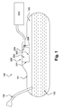
- Figure 1 depicts a sectional schematic view of a fuel tank 100 having a tank shell 101.
- a tank filler pipe 104 provides an entry for fuel into the fuel tank 100.
- the fuel tank 100 normally has a certain volume of liquid fuel 102 and vapor space 103.
- a valve apparatus 200 according to the present invention is disposed within the fuel tank 100.
- the valve apparatus 200 can be welded on the outer face or the inner face (i.e. internal wall) of the tank shell 101.
- the valve apparatus 200 can also be attached by using rivet-snapping or dovetail technique. Such techniques are well known for a skill person and should therefore not be explained further.
- FIGS 2 and 3 show the valve apparatus 200 according to a particular embodiment of the present invention, with a float and without a float, respectively.
- the valve apparatus 200 comprises a casing 201 defining a main chamber 202.
- the main chamber 202 comprises an inlet orifice 203 and an outlet orifice 204.
- the valve apparatus 200 comprises a cover 205, which may either be moulded as one part with the casing 201 or it may form a separate part joined to the latter by any known means (mechanical fastening with a seal; welding etc.).
- the cover 205 is a separate part and is clipped on the top of the casing 201.
- the cover 205 comprises a coupling section 206 (e.g., a quick-connect coupling or a fir-tree nipple) configured to facilitate coupling to one end of a tube or a pipe and of which other end is connected to a carbon canister 300 (see figure 1 ).
- a venting channel 207 is defined between a portion of the cover 205 and a portion of the casing 201 and is adapted to put in fluid communication the outlet orifice 204 and the coupling section 206.
- the valve apparatus 200 comprises extracting means 208 and a float 209 equipped with a needle 210 (i.e. closure element) capable of closing off the outlet orifice 204.
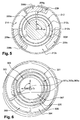
- the extracting means 208 comprise a spiral-shaped wall (i.e. spiral structure).
- the spiral-shaped wall referenced 212 in figure 5
- the spiral-shaped wall 212 partitions the main chamber 202 into a plurality of areas (or channels). More particularly, the spiral-shaped wall 212 delimits an outer area 212a, an intermediate area 212b and an inner area 212c. Those areas form an extended flow path.
- the main chamber is provided with an opening 214 for entry of fluid (gas and/or liquid) into the outer area 212a of the spiral structure. As illustrated, the opening 214 can be transversally offset with respect to the axis (A) of the casing (see figure 3 ). With this arrangement, the corking flow can be reduced.
- the inner area 212c is in fluid communication with the outlet orifice 204.
- the float 209 comprises a main float 209a and three secondary floats (or satellite floats) 209b, 209c and 209d.
- the secondary floats 209b, 209c and 209d are connected to the main float 209a by three connecting members 209e, 209f and 209g, respectively.
- the main float 209a supports the needle 210 and is slidably disposed in the inner area 212c.
- the secondary floats 209b, 209c and 209d are slidably disposed in the outer area 212a.
- the spiral-shaped wall 212 comprises a plurality of slits (not shown) into which the connecting members may be slidably disposed.
- the float 209 i.e. main float 209a, secondary floats 209b, 209c, 209d, and connecting members 209e, 209f, 209g
- the spiral-shaped wall 212 is adapted to fulfill the following three functions:
- the fuel in the tank passes through the inlet orifice 203, the fuel flows towards the opening 214 and enters the outer area 212a.
- the fuel is forced to circulate within the casing along the extended flow path.
- the secondary floats 209b, 209c, 209d start moving upward by buoyancy. Since the secondary floats 209b, 209c, 209d are connected to the main float 209a by means of the connecting members 209e, 209f, 209g, the main float 209a is simultaneously moved upward. Therefore, the needle 210 can close off the outlet orifice 204, before the fuel reaches the inner area 212c. Thus the fuel can be prevented from flowing out through the outlet orifice 204 before the outlet orifice 204 is closed by the needle 210.
- the spiral structure 212 of figure 5 can be replaced by a multi-concentric wall structure.
- FIG 6 showing a top cross-section view of a multi-concentric wall structure comprising a plurality of concentric walls.
- the concentric walls 301, 302, 303 delimit an outer area 304, a first and second intermediate areas 305, 306 and an inner area 307. Those areas form an extended flow path.
- the main chamber is provided with an opening 308 for entry of fluid (gas and/or liquid) into the outer area 304.
- the opening 308 can be transversally offset with respect to the axis (A) of the casing (see figure 3 ). With this arrangement, the corking flow can be reduced.
- the inner area 307 is in fluid communication with the outlet orifice 204.
- Each concentric wall 301, 302, 303 comprises a passage 301a, 302a, 303a.
- the outer area 304 can be in fluid communication with the first intermediate area 305 via the passage 301a
- the first intermediate area 305 can be in fluid communication with the second intermediate area 306 via the passage 302a
- the second intermediate area 306 can be in fluid communication with the inner area 307 via the passage 303a.
- the passages 301a, 302a, 303a are arranged at 180°to one another.
- the fuel is forced to circulate within the casing along the extended flow path (not represented).
- the float described in connection to figure 5 can be used in the arrangement of figure 6 .
- the concentric walls may comprise appropriate slits for receiving and guiding the connecting members.
- the valve apparatus 200 comprises a preloaded spring 220.
- the preloaded spring 220 and the gravity push the float towards the upward position (i.e. closed position of the valve) .
- the valve apparatus 200 comprises a collection and discharge chamber 211 which is enclosed within the main chamber 202 and positioned at the bottom of the main chamber 202. It is to note that the collection and discharge chamber 211 is in fluid communication with the spiral structure 212 of figure 5 (respectively, the concentric wall structure 301, 302, 303 of figure 6 ) via the opening 214 (respectively, the opening 308 of figure 6 ).
- the collection and discharge chamber 211 may either be moulded as one part with the casing 201 or it may form a separate part joined to the latter by any known means (mechanical fastening with a seal; welding etc.).
- the collection and discharge chamber 211 is a separate part and is clipped on the bottom of the casing 201.
- the collection and discharge chamber 211 has a through hole which corresponds to the inlet orifice 203.
- the collection and discharge chamber can have a main part made integral with the casing and a separate cover part which is mountable on said main part.
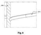
- the spiral-shaped wall 212 comprises protruding grooves 213 adapted to guide the fuel droplets towards the collection and discharge chamber 211.
- Figure 4 is an enlarged view of a protruding groove 213.
- the protruding groove 213 protrudes outwardly from the surface of the wall 212 and has a general gutter shape.
- the protruding grooves 213 are made integral with the spiral-shaped wall 212.
- the vapour stream flows towards the opening 214 and enters the spiral structure 212.
- the fuel droplets present in the vapour stream are separated from the vapour stream as and when the vapour stream circulates along the spiral-shaped wall 212.
- the fuel droplets present in the vapour stream can be separated by centrifugal forces from the vapour stream.
- the fuel droplets drip along the protruding groove 213 to end up into the collection and discharge chamber 211. Therefore, it is possible to reduce the risk of liquid carried over into the canister 300.
- valve apparatus according to the present invention and described above in relation to figures 1-6 , can be separately manufactured by injection molding process and then assembled together.
- the entire or major part of the constituent elements of the valve apparatus according to the present invention can be manufactured by additive manufacturing process.
- Said additive manufacturing process can be laser additive manufacturing, laser engineered net shaping, selective laser sintering, electron-beam projection lithography, fused deposition modeling or electron beam melting. Such processes are known in the art.
- the float 209 shown in figure 5 can have less or more than three secondary floats.
- one single member can support at least two secondary floats.
- passages 301a, 302a, 303a shown in figure 6 can be offset differently relative to each other.
- the concentric areas can be arranged in a staged manner.
- the area with the smallest diameter can be positioned at the lowest stage (i.e. closest to the bottom of the main chamber) and can be configured to be fed with fluid from a next outer area with a larger diameter, which is positioned at the next stage above.
- the length of the extended flow path can be further increased.
- valve apparatus of the present invention can also be used in a vehicle tank for the storage of ammonia precursor solutions or ammonia solutions,the latter being especially interesting because of their high vapor pressure.
Abstract
It is proposed a valve apparatus for use in a liquid tank, the valve apparatus comprising:
- a casing (201) defining a main chamber (202), the main chamber having an inlet orifice (203) and at least one outlet orifice (204);
- extracting means (208) comprising at least one wall member extending substantially across the main chamber and being adapted for extracting droplets present in a vapour stream coming from the liquid tank and entering the main chamber via the inlet orifice;
- a float (209) comprising a closure element (210) capable of closing off the outlet orifice(s), the float being slidably mounted along the at least one wall member.
Description
- The present invention relates to a valve apparatus for the venting of a liquid tank, in particular a fuel tank with which a motor vehicle may be equipped.
- In fuel systems it is known to use a float valve to avoid allowing substantial amounts of liquid fuel to pass into the venting line that runs to a vapour storage canister.
- It is known to use float valves equipped with baffles (or walls) to reduce the risk of liquid carried over into the canister. Such baffles are generally designed to separate the liquid droplets carried by the vapour stream. An example of a known float valve equipped with baffles is described in patent document
US 6,405,747 . These known float valves are bulky and are not suited for placement in an internal area of the tank where there is minimal height between the bottom of the tank and the top of the tank as well as minimal height between the full tank liquid height and the top of the tank. These known float valves can be made short and wide, but since the height at which the valve shuts off becomes close to the height of the venting orifice, there is an increasing risk of fluid getting through before the valve closes. - The object of embodiments of the invention is to provide a valve apparatus of reduced height, and which reduces or suppresses the risk of outflow of liquid to a canister for example.
- According to an aspect of the invention, there is provided a valve apparatus for use in a liquid tank, said valve apparatus comprising:
- a casing defining a main chamber, the main chamber having an inlet orifice and at least one outlet orifice;
- a float comprising a closure element capable of closing off the outlet orifice(s), the float being movable upward and downward inside the main chamber;
- extracting means comprising at least one wall member extending substantially across the main chamber and being adapted for extracting droplets present in a vapour stream coming from the liquid tank and entering the main chamber via the inlet orifice;
- The valve apparatus according to the invention is intended for the venting of a tank, which may contain any liquid. In particular, the liquid may be a fuel. The tank may be intended for any use, especially for equipping a vehicle and more especially for equipping a motor vehicle. In a particular embodiment, the size and shape of the casing of the valve apparatus according to the invention can be chosen in such a way that the valve apparatus can be entirely disposed in the interior of the tank, preferably by attachment to the inside of the top wall of the tank. In a particular embodiment, the casing of the valve apparatus comprises a top surface comprising a bonding feature for facilitating the welding of the casing to the interior of the tank. In another particular embodiment, the casing of the valve apparatus comprises bonding features for facilitating the welding of the casing to the external surface of the top wall of the tank. In another particular embodiment, the casing of the valve apparatus is a part or is fixed to a flange or a support adapted to be attached to the tank. The main chamber can have one outlet orifice. Alternatively, the main chamber can have several outlet orifices. With this latter particular configuration, the reopening pressure can be reduced.
- Embodiments of the invention are based inter alia on the inventive insight that the float and the extracting means can be slotted together to provide a sliding arrangement. More in particular, the inventors have realised that the float and the extracting means do not need to be positioned at two different heights (i.e. stacked one on top of the other) within the same chamber, and that it is possible to overlap those two elements in a manner such that the float can slide over the extracting means. In other words, embodiments of the invention can perform the same functionalities as prior art solutions, whilst having the advantage of being more compact.
The wall member(s) act(s) as a liquid vapour separator unit and as a sliding guide for the float. The float is slidable over at least one portion of the wall member(s).
The float is slidable from a downward position in which the outlet orifice(s) is(are) opened and an upward position in which the outlet orifice(s) is(are) closed off by the closure element.
In an advantageous embodiment, the wall member(s) extend(s) vertically from the bottom to the top of the main chamber to facilitate the upward and downward sliding movements of the float.
In an advantageous embodiment, the extracting means are made integral with the casing. The extracting means and the casing can be manufactured by injection molding process or by additive manufacturing process (i.e. 3D printing). - The valve apparatus according to the invention allows a liquid tank to be vented, both in normal operation and when filling. Further, it has the function of preventing ingress of liquid in the event of a vehicle rolling over or being excessively tilted.
- Advantageously, the constituent elements of the valve apparatus may be made of any material. Preferably, they are based on a thermoplastic. In this case, it is obviously convenient to choose the material or materials in such a way that they withstand the operating stresses. Of course, the materials chosen must be inert with respect to the liquids with which they have to be in contact, in particular inert with respect to fuels.
In particular in the case in which the liquid tank is a fuel tank made of plastic, most of the constituent elements of the valve apparatus according to the invention are also made of plastic. The term "plastic" is understood to mean any polymeric synthetic material, whether thermoplastic or thermosetting, as well as blends of at least two of these materials. The intended polymers comprise both homopolymers and copolymers (especially binary or ternary copolymers). Examples of such copolymers are, non-limitingly: random copolymers, linear block copolymers, non-linear block copolymers, and graft copolymers. Thermoplastic polymers, including thermoplastic elastomers, and blends thereof are preferred. Any type of thermoplastic polymer or copolymer is suitable. - In a particular embodiment, the closure element is made of rubber. In a particular embodiment, the closure element can be a needle seal or a ribbon seal.
- In a first particular configuration, the extracting means comprise a plurality of concentric walls defining a plurality of concentric areas, each concentric wall comprising a passage adapted to allow two adjacent concentric areas to be in fluid communication with each other.
In an advantageous embodiment, the plurality of concentric areas comprise at least an outer area in fluid communication with the inlet orifice and a central inner area in fluid communication with the outlet orifice(s), and wherein the float comprises a main float supporting the closure element and at least one secondary float connected to the main float, said at least one secondary float being slidably disposed in the outer area and said main float being slidably disposed in the central inner area. Advantageously, the passages of the concentric walls are offset to one another, preferably they are arranged crosswise (90°) or at opposite (180°) to one another. This geometry prevents direct flow between the various partitions (i.e. concentric areas) and therefore creates an optimal labyrinth effect.
With this first particular configuration, it is proposed to use the plurality of concentric walls to create an extended flow path between the inlet orifice and the outlet orifice(s). By "extended flow path" it is understood that the distance from the inlet orifice to the outlet orifice(s) is longer compare to the distance of a straight-line path between the inlet orifice and the outlet orifice(s). Thus, the time that it takes to a fluid for traveling along the extended flow path is greater than the time it would take to the fluid for traveling along the straight-line path. In a particular embodiment, the length of the extended flow path can be set such that it is at least two times, preferably higher than four times, longer than the straight-line path. In this first particular configuration, when the liquid in the liquid tank passes through the inlet orifice, the secondary float(s) starts to move upward by buoyancy. Advantageously, the secondary float(s) pull the main float to move upward, since the secondary float(s) is linked (i.e. connected) to the main float. Therefore, the closure element (moved by the main float) can close off the outlet orifice(s), before the liquid reaches the central inner area. It is an advantage of this first particular configuration that the liquid can be prevented from flowing out of the outlet orifice(s). - In a second particular configuration, the extracting means comprise a spiral-shaped wall or helical-shaped wall. With this second particular configuration, it is proposed to use a spiral-shaped wall to create an extended flow path between the inlet orifice and the outlet orifice(s). Another advantage of this second particular configuration is that the pressure drop in the valve can be reduced.
The external shape of the float is obviously matched to that of the spiral-shaped wall in which it has to be able to slide.
In a first advantageous embodiment, the float comprises a spiral-shaped float. Thus, the spiral-shaped float starts to move upward by buoyancy when the liquid passes through the inlet orifice and the closure element (mounted on the center of the spiral-shaped float) can close off the outlet orifice(s), before the liquid reaches the center of the spiral that is arranged to be in fluid communication with the outlet orifice(s). Therefore, liquid can be prevented from flowing out of the outlet orifice(s).
In a second advantageous embodiment, the float comprises a main float supporting the closure element and at least one secondary float connected to the main float, said at least one secondary float being slidably disposed in a first area delimited by a first portion of the spiral-shaped wall, the first area being in fluid communication with the inlet orifice, and said main float being slidably disposed in a second area delimited by a second portion of the spiral-shaped wall, the second area being in fluid communication with the outlet orifice(s). Thus, when the liquid in the liquid tank passes through the inlet orifice, the secondary float(s) starts to move upward by buoyancy, thus pulling the main float to move upward. Therefore, the closure element can close off the outlet orifice(s), before the liquid reaches the second area. Therefore, liquid can be prevented from flowing out of the outlet orifice(s). - In a particular embodiment, the main chamber comprises an opening for entry of fluid into the first area of the spiral, and wherein the position of the opening is transversally offset with respect to the position of the inlet orifice. With this arrangement, the length of the extended flow path is further increased. Moreover,
it is an advantage of this embodiment that the upward (axial) forces applied by the fluid to the float can be suppressed or at least reduced, by arranging said opening away from the center of the casing (i.e. position of the inlet orifice). In other words, the corking flow can be reduced, thus allowing the valve apparatus to operate at a higher flow rate. Advantageously, the extended flow path and said opening may be shaped and arranged in a way such that the valve apparatus of the present invention can operate as a Fill Limit Vent Valve (FLVV).
In the particular case when the valve apparatus is used in a fuel tank, said fluid is a mixture of air and fuel vapour. - In a particular embodiment, the casing of the valve apparatus further comprises a collection and discharge chamber for the droplets, which is positioned at the bottom of the main chamber. Thus, the droplets that have been entrained with the gases can be collected and returned back to the tank, for example by gravity.
In a particular embodiment, the extracting means comprise protruding grooves adapted to guide the droplets towards the collection and discharge chamber. Advantageously, the droplets drip along those protruding grooves to end up into the collection and discharge chamber. Such protruding grooves secure the collection of the droplets and reduce the risk of outflow of liquid. The grooves can protrude inwardly or outwardly from the surface of the wall members of the extracting means. - According to another aspect of the invention, there is provided a valve assembly comprising a common support supporting a valve apparatus as described above. In a particular embodiment, the common support is further adapted to support other components: another type of valve, a sensor, a fluid conduct, electrical wires.
- According to another aspect of the invention, there is provided a fuel tank comprising at least one valve apparatus or valve assembly as described above, said at least one valve apparatus or valve assembly being attached to said fuel tank.
- According to another aspect of the invention, there is provided a motor vehicle comprising a fuel tank as described above.
- The accompanying drawings are used to illustrate presently preferred non-limiting exemplary embodiments of devices of the present invention. The above and other advantages of the features and objects of the invention will become more apparent and the invention will be better understood from the following detailed description when read in conjunction with the accompanying drawings, in which:
-
Figure 1 illustrates schematically a valve apparatus according to an embodiment of the invention, installed in an exemplary manner in a fuel tank; -
Figure 2 illustrates schematically a cross-section view of the valve apparatus offigure 1 , with a float; -
Figure 3 illustrates schematically a cross-section view of the valve apparatus offigure 1 , without a float; -
Figure 4 illustrates schematically a protruding groove of the valve apparatus offigure 1 ; -
Figure 5 illustrates schematically a top cross-section view of extracting means of the valve apparatus offigure 1 ; and -
Figure 6 illustrates schematically a top cross-section view of extracting means according to another embodiment of the present invention. - Throughout the figures, like reference numerals have been used to designate like features.
- The present invention provides a valve apparatus for the venting of a liquid tank. In a particular embodiment, the valve apparatus of the present invention can be used in a fuel tank of a motor vehicle. The valve apparatus of the present invention can work as a Roll-Over Valve (ROV) or a Fill Limit Vent Valve (FLVV).
- "Fuel" is understood to designate a mix of liquid or liquefied hydrocarbons, as normally used to power internal combustion engines, including fuels known as gasoline, diesel, ethanol, etc. The valve apparatus of the present invention is particularly suited for venting fuel tanks containing fuel having a relatively high vapour pressure such as gasoline.
- The fuel tank used in conjunction with the invention is preferably made of plastic.
The wall of the fuel tank may be composed of a single thermoplastic layer, or of two layers. One or more other possible additional layers may, advantageously, be composed of layers made of a material that is a barrier to liquids and/or gases. Preferably, the nature and thickness of the barrier layer are chosen so as to minimize the permeability of liquids and gases in contact with the internal surface of the tank. Preferably, this layer is based on a barrier resin, that is to say a resin that is impermeable to the fuel such as, for example, EVOH (a partially hydrolysed ethylene/vinyl acetate copolymer). Alternatively, the tank may be subjected to a surface treatment (fluorination or sulphonation) for the purpose of making it impermeable to the fuel. - When the valve apparatus according to the present invention is attached to a fuel tank, it is preferably attached thereto by welding. The welding can be performed during the parison moulding stage of the fuel tank. Alternatively, the welding can be performed after or during the fuel tank finishing operations (boring and welding).
- Alternatively, the valve apparatus can be attached onto the inner side of an injected shell of a fuel tank or a urea tank by hot plate welding or laser welding.
Alternatively, the valve apparatus can also be attached onto the inner side of a tank shell by an infra-red welding process. Such process is for example described in patent documentUS 7,829,819 .
Alternatively, the valve apparatus can be attached to the tank by plastic overmoulding process.
Alternatively, the valve apparatus can be attached to the tank by a locking ring system or by any other mean known in the state of the art. -
Figure 1 depicts a sectional schematic view of afuel tank 100 having atank shell 101. Atank filler pipe 104 provides an entry for fuel into thefuel tank 100. Thefuel tank 100 normally has a certain volume ofliquid fuel 102 andvapor space 103. Avalve apparatus 200 according to the present invention is disposed within thefuel tank 100. Thevalve apparatus 200 can be welded on the outer face or the inner face (i.e. internal wall) of thetank shell 101. Thevalve apparatus 200 can also be attached by using rivet-snapping or dovetail technique. Such techniques are well known for a skill person and should therefore not be explained further. -
Figures 2 and 3 show thevalve apparatus 200 according to a particular embodiment of the present invention, with a float and without a float, respectively.
Thevalve apparatus 200 comprises acasing 201 defining amain chamber 202. Themain chamber 202 comprises aninlet orifice 203 and anoutlet orifice 204. Thevalve apparatus 200 comprises acover 205, which may either be moulded as one part with thecasing 201 or it may form a separate part joined to the latter by any known means (mechanical fastening with a seal; welding etc.). In the illustrated embodiment, thecover 205 is a separate part and is clipped on the top of thecasing 201. Thecover 205 comprises a coupling section 206 (e.g., a quick-connect coupling or a fir-tree nipple) configured to facilitate coupling to one end of a tube or a pipe and of which other end is connected to a carbon canister 300 (seefigure 1 ). A ventingchannel 207 is defined between a portion of thecover 205 and a portion of thecasing 201 and is adapted to put in fluid communication theoutlet orifice 204 and thecoupling section 206.
Thevalve apparatus 200 comprises extracting means 208 and afloat 209 equipped with a needle 210 (i.e. closure element) capable of closing off theoutlet orifice 204. In the example shown onfigures 2 and 3 , the extracting means 208 comprise a spiral-shaped wall (i.e. spiral structure). Advantageously, the spiral-shaped wall (referenced 212 infigure 5 ) is made integral with thecasing 201. - Reference will now be made particularly to
figure 5 showing a top cross-section view of the arrangement of the spiral-shapedwall 212 and thefloat 209.
As shown infigure 5 , the spiral-shapedwall 212 partitions themain chamber 202 into a plurality of areas (or channels). More particularly, the spiral-shapedwall 212 delimits anouter area 212a, anintermediate area 212b and aninner area 212c. Those areas form an extended flow path. The main chamber is provided with anopening 214 for entry of fluid (gas and/or liquid) into theouter area 212a of the spiral structure. As illustrated, theopening 214 can be transversally offset with respect to the axis (A) of the casing (seefigure 3 ). With this arrangement, the corking flow can be reduced. Theinner area 212c is in fluid communication with theoutlet orifice 204.
Thefloat 209 comprises amain float 209a and three secondary floats (or satellite floats) 209b, 209c and 209d. Thesecondary floats main float 209a by three connectingmembers main float 209a supports theneedle 210 and is slidably disposed in theinner area 212c. Thesecondary floats outer area 212a. The spiral-shapedwall 212 comprises a plurality of slits (not shown) into which the connecting members may be slidably disposed. With this arrangement, the float 209 (i.e.main float 209a,secondary floats members wall 212.
Therefore, the spiral-shapedwall 212 is adapted to fulfill the following three functions: - guide the
float 209 in the vertical direction, the float being movable upward and downward inside the main chamber and over the spiral-shapedwall 212; - create an extended flow path (not represented) between the
inlet orifice 203 and theoutlet orifice 204; and - separate the fuel droplets present in a vapour stream entering the
main chamber 202 via theinlet orifice 203. - When the fuel in the tank passes through the
inlet orifice 203, the fuel flows towards theopening 214 and enters theouter area 212a. The fuel is forced to circulate within the casing along the extended flow path. When the fuel circulates in theouter area 212a, thesecondary floats secondary floats main float 209a by means of the connectingmembers main float 209a is simultaneously moved upward. Therefore, theneedle 210 can close off theoutlet orifice 204, before the fuel reaches theinner area 212c. Thus the fuel can be prevented from flowing out through theoutlet orifice 204 before theoutlet orifice 204 is closed by theneedle 210. - The
spiral structure 212 offigure 5 can be replaced by a multi-concentric wall structure.
Reference will now be made tofigure 6 showing a top cross-section view of a multi-concentric wall structure comprising a plurality of concentric walls.
As shown infigure 6 , theconcentric walls outer area 304, a first and secondintermediate areas inner area 307. Those areas form an extended flow path. The main chamber is provided with anopening 308 for entry of fluid (gas and/or liquid) into theouter area 304. As illustrated, theopening 308 can be transversally offset with respect to the axis (A) of the casing (seefigure 3 ). With this arrangement, the corking flow can be reduced. Theinner area 307 is in fluid communication with theoutlet orifice 204. Eachconcentric wall passage outer area 304 can be in fluid communication with the firstintermediate area 305 via thepassage 301a, the firstintermediate area 305 can be in fluid communication with the secondintermediate area 306 via thepassage 302a, and the secondintermediate area 306 can be in fluid communication with theinner area 307 via thepassage 303a. In the illustrated embodiment, thepassages
When the fuel in the tank passes through theinlet orifice 203, the fuel flows towards theopening 308 and enters theouter area 304. The fuel is forced to circulate within the casing along the extended flow path (not represented).
The float described in connection tofigure 5 can be used in the arrangement offigure 6 . In this case, the concentric walls may comprise appropriate slits for receiving and guiding the connecting members. - As shown in
figure 2 , thevalve apparatus 200 comprises apreloaded spring 220. In the event of the tank rolling over, thepreloaded spring 220 and the gravity push the float towards the upward position (i.e. closed position of the valve) . - As shown in
figures 2 and 3 , thevalve apparatus 200 comprises a collection anddischarge chamber 211 which is enclosed within themain chamber 202 and positioned at the bottom of themain chamber 202. It is to note that the collection anddischarge chamber 211 is in fluid communication with thespiral structure 212 offigure 5 (respectively, theconcentric wall structure figure 6 ) via the opening 214 (respectively, theopening 308 offigure 6 ).
The collection anddischarge chamber 211 may either be moulded as one part with thecasing 201 or it may form a separate part joined to the latter by any known means (mechanical fastening with a seal; welding etc.). In the illustrated embodiment, the collection anddischarge chamber 211 is a separate part and is clipped on the bottom of thecasing 201. The collection anddischarge chamber 211 has a through hole which corresponds to theinlet orifice 203. In another embodiment, the collection and discharge chamber can have a main part made integral with the casing and a separate cover part which is mountable on said main part.
In the particular embodiment described in relation tofigures 2 and 3 , the spiral-shapedwall 212 comprises protrudinggrooves 213 adapted to guide the fuel droplets towards the collection anddischarge chamber 211.Figure 4 is an enlarged view of a protrudinggroove 213. In the illustrated example, the protrudinggroove 213 protrudes outwardly from the surface of thewall 212 and has a general gutter shape. Advantageously, the protrudinggrooves 213 are made integral with the spiral-shapedwall 212.
When a vapour stream passes through theinlet orifice 203, the vapour stream flows towards theopening 214 and enters thespiral structure 212. The fuel droplets present in the vapour stream are separated from the vapour stream as and when the vapour stream circulates along the spiral-shapedwall 212. In a particularly advantageous embodiment, the fuel droplets present in the vapour stream can be separated by centrifugal forces from the vapour stream. The fuel droplets drip along the protrudinggroove 213 to end up into the collection anddischarge chamber 211. Therefore, it is possible to reduce the risk of liquid carried over into thecanister 300. - It is to note that the constituent elements of the valve apparatus according to the present invention and described above in relation to
figures 1-6 , can be separately manufactured by injection molding process and then assembled together. - In an alternative, the entire or major part of the constituent elements of the valve apparatus according to the present invention can be manufactured by additive manufacturing process. Said additive manufacturing process can be laser additive manufacturing, laser engineered net shaping, selective laser sintering, electron-beam projection lithography, fused deposition modeling or electron beam melting. Such processes are known in the art.
- Although the invention has been described hereinabove by reference to specific embodiments, this is done for illustrative and not for limiting purposes. Moreover, features disclosed in connection with one particular embodiment may be combined with features from other embodiments to obtain the same technical effects and advantages, without leaving the scope of the present invention.
- For example, in an alternative embodiment, the
float 209 shown infigure 5 can have less or more than three secondary floats. In another particular embodiment, one single member can support at least two secondary floats. - In yet an alternative embodiment, the
passages figure 6 can be offset differently relative to each other. - In yet an alternative embodiment, the concentric areas (or channels) can be arranged in a staged manner. For example, the area with the smallest diameter can be positioned at the lowest stage (i.e. closest to the bottom of the main chamber) and can be configured to be fed with fluid from a next outer area with a larger diameter, which is positioned at the next stage above. With this arrangement, the length of the extended flow path can be further increased.
- It is to note that the valve apparatus of the present invention can also be used in a vehicle tank for the storage of ammonia precursor solutions or ammonia solutions,the latter being especially interesting because of their high vapor pressure.
- The skilled person will appreciate that other variants of the present invention may be within the scope of the attached claims.
Claims (14)
- A valve apparatus for use in a liquid tank, said valve apparatus comprising:- a casing (201) defining a main chamber (202), the main chamber having an inlet orifice (203) and at least one outlet orifice (204);- a float (209) comprising a closure element (210) capable of closing off the outlet orifice(s), the float being movable upward and downward inside the main chamber;- extracting means (208) comprising at least one wall member extending substantially across the main chamber and being adapted for extracting droplets present in a vapour stream coming from the liquid tank and entering the main chamber via the inlet orifice,wherein the float is slidably mounted along said at least one wall member.
- The valve apparatus according to claim 1, wherein the extracting means comprise a plurality of concentric walls (301, 302, 303) defining a plurality of concentric areas, each concentric wall comprising a passage adapted to allow two adjacent concentric areas to be in fluid communication with each other.
- The valve apparatus according to claim 2, wherein the plurality of concentric areas comprise at least an outer area (304) in fluid communication with the inlet orifice and a central inner area (307) in fluid communication with the outlet orifice(s), and wherein the float comprises a main float supporting the closure element and at least one secondary float connected to the main float, said at least one secondary float being slidably disposed in the outer area and said main float being slidably disposed in the central inner area.
- The valve apparatus according to claim 3, wherein the float comprises at least one connecting member for connecting said at least one secondary float to the main float, and wherein the concentric walls comprise at least one slit into which said at least one connecting member is inserted.
- The valve apparatus according to claim 1, wherein the extracting means comprise a spiral-shaped wall (212).
- The valve apparatus according to claim 5, wherein the float comprises a spiral-shaped float.
- The valve apparatus according to claim 5, wherein the float comprises a main float (209a) supporting the closure element and at least one secondary float (209b, 209c, 209d) connected to the main float, said at least one secondary float being slidably disposed in a first area (212a) delimited by a first portion of the spiral-shaped wall, the first area being in fluid communication with the inlet orifice, and said main float being slidably disposed in a second area (212c) delimited by a second portion of the spiral-shaped wall, the second area being in fluid communication with the outlet orifice(s).
- The valve apparatus according to claim 7, wherein the float comprises at least one connecting member (209e, 209f, 209g) for connecting said at least one secondary float to the main float, and wherein the spiral-shaped wall comprises at least one slit into which said at least one connecting member is inserted.
- The valve apparatus according to claim 7 or 8, wherein the main chamber comprises an opening (214;308) for entry of fluid into the first area, and wherein the position of the opening is transversally offset with respect to the position of the inlet orifice (203).
- The valve apparatus according to the preceding claims, wherein it comprises a collection and discharge chamber (211) for the droplets, which is positioned at the bottom of the main chamber.
- The valve apparatus according to claim 10, wherein the extracting means comprise protruding grooves (213) adapted to guide the droplets towards the collection and discharge chamber.
- A valve assembly comprising a common support supporting a valve apparatus according to any of claims 1-11.
- A fuel tank comprising at least one valve apparatus according to any of claims 1-11, said at least one valve apparatus being attached to said fuel tank.
- A motor vehicle comprising a fuel tank according to claim 13.
Priority Applications (5)
| Application Number | Priority Date | Filing Date | Title |
|---|---|---|---|
| EP15198453.1A EP3178687A1 (en) | 2015-12-08 | 2015-12-08 | Valve apparatus for venting a liquid tank |
| CN201680072350.6A CN108367672B (en) | 2015-12-08 | 2016-12-07 | Valve device for venting a liquid tank |
| EP16809357.3A EP3386791A1 (en) | 2015-12-08 | 2016-12-07 | Valve apparatus for venting a liquid tank |
| PCT/EP2016/080102 WO2017097841A1 (en) | 2015-12-08 | 2016-12-07 | Valve apparatus for venting a liquid tank |
| US15/780,439 US10632837B2 (en) | 2015-12-08 | 2016-12-07 | Valve apparatus for venting a liquid tank |
Applications Claiming Priority (1)
| Application Number | Priority Date | Filing Date | Title |
|---|---|---|---|
| EP15198453.1A EP3178687A1 (en) | 2015-12-08 | 2015-12-08 | Valve apparatus for venting a liquid tank |
Publications (1)
| Publication Number | Publication Date |
|---|---|
| EP3178687A1 true EP3178687A1 (en) | 2017-06-14 |
Family
ID=54843712
Family Applications (2)
| Application Number | Title | Priority Date | Filing Date |
|---|---|---|---|
| EP15198453.1A Withdrawn EP3178687A1 (en) | 2015-12-08 | 2015-12-08 | Valve apparatus for venting a liquid tank |
| EP16809357.3A Withdrawn EP3386791A1 (en) | 2015-12-08 | 2016-12-07 | Valve apparatus for venting a liquid tank |
Family Applications After (1)
| Application Number | Title | Priority Date | Filing Date |
|---|---|---|---|
| EP16809357.3A Withdrawn EP3386791A1 (en) | 2015-12-08 | 2016-12-07 | Valve apparatus for venting a liquid tank |
Country Status (4)
| Country | Link |
|---|---|
| US (1) | US10632837B2 (en) |
| EP (2) | EP3178687A1 (en) |
| CN (1) | CN108367672B (en) |
| WO (1) | WO2017097841A1 (en) |
Cited By (1)
| Publication number | Priority date | Publication date | Assignee | Title |
|---|---|---|---|---|
| CN109704265A (en) * | 2017-10-26 | 2019-05-03 | 通用汽车环球科技运作有限责任公司 | For filling the exhaust stream guiding piece on head |
Families Citing this family (5)
| Publication number | Priority date | Publication date | Assignee | Title |
|---|---|---|---|---|
| DE102013013212A1 (en) * | 2013-08-09 | 2015-02-12 | Kautex Textron Gmbh & Co. Kg | Universal shut-off valve |
| CN109132264A (en) * | 2018-09-12 | 2019-01-04 | 江苏新天宝机械有限公司 | A kind of anti sling liquid respirator |
| US11933214B2 (en) | 2019-02-06 | 2024-03-19 | Abc Technologies Inc. | Multi-chamber reservoir assembly |
| CN111618068B (en) * | 2020-05-19 | 2022-02-11 | 南京信息职业技术学院 | Electric spiral taper rod squeezing oil drain hole equipment for oil tank |
| DE102020207834A1 (en) | 2020-06-24 | 2021-12-30 | Alfmeier Präzision SE | VENTILATION VALVE WITH IMPACT WALL AS SPLASH PROTECTION |
Citations (5)
| Publication number | Priority date | Publication date | Assignee | Title |
|---|---|---|---|---|
| US5413137A (en) * | 1994-02-14 | 1995-05-09 | Borg-Warner Automotive, Inc. | Fuel vapor vent assembly with liquid trap |
| US6405747B1 (en) | 1999-10-29 | 2002-06-18 | Stant Manufacturing, Inc. | Fuel tank vent valve with liquid carryover filter |
| EP1488947A2 (en) * | 2003-06-16 | 2004-12-22 | Stant Manufacturing Inc. | Fuel tank vent system with liquid fuel filter |
| EP1642760A2 (en) * | 2004-10-01 | 2006-04-05 | Stant Manufacturing Inc. | Fuel tank vent system with variable-height fuel level shut-off port |
| US7829819B2 (en) | 2007-02-08 | 2010-11-09 | Automotive Components Holdings, Llc | Attaching a component to an internal surface of a tank formed of polymer |
Family Cites Families (9)
| Publication number | Priority date | Publication date | Assignee | Title |
|---|---|---|---|---|
| US5944044A (en) * | 1996-05-10 | 1999-08-31 | Stant Manufacturing Inc. | Tank venting control system |
| US6331021B1 (en) * | 1998-12-07 | 2001-12-18 | Ford Global Technolobies, Inc. | Fuel system vent line |
| US6634341B2 (en) * | 1999-04-28 | 2003-10-21 | Walbro Corporation | Vent and rollover valve and fuel pump module |
| US6578597B2 (en) * | 2001-03-08 | 2003-06-17 | Stant Manufacturing Inc. | Fuel tank vent system with liquid fuel filter |
| US6701950B2 (en) * | 2001-04-09 | 2004-03-09 | Stant Manufacturing Inc. | Fuel tank vent system |
| FR2886366B1 (en) * | 2005-05-24 | 2007-07-06 | Inergy Automotive Systems Res | LIQUID TANK AIR SUPPLY SYSTEM |
| JP5786788B2 (en) * | 2011-09-26 | 2015-09-30 | 京三電機株式会社 | Full tank control valve device |
| JP5874601B2 (en) * | 2012-10-31 | 2016-03-02 | 豊田合成株式会社 | Fuel shut-off valve |
| EP3418095B1 (en) * | 2017-06-22 | 2019-04-24 | Magna Steyr Fuel Systems GesmbH | Bleed nipple and tank assembly |
-
2015
- 2015-12-08 EP EP15198453.1A patent/EP3178687A1/en not_active Withdrawn
-
2016
- 2016-12-07 CN CN201680072350.6A patent/CN108367672B/en not_active Expired - Fee Related
- 2016-12-07 WO PCT/EP2016/080102 patent/WO2017097841A1/en active Application Filing
- 2016-12-07 EP EP16809357.3A patent/EP3386791A1/en not_active Withdrawn
- 2016-12-07 US US15/780,439 patent/US10632837B2/en active Active
Patent Citations (5)
| Publication number | Priority date | Publication date | Assignee | Title |
|---|---|---|---|---|
| US5413137A (en) * | 1994-02-14 | 1995-05-09 | Borg-Warner Automotive, Inc. | Fuel vapor vent assembly with liquid trap |
| US6405747B1 (en) | 1999-10-29 | 2002-06-18 | Stant Manufacturing, Inc. | Fuel tank vent valve with liquid carryover filter |
| EP1488947A2 (en) * | 2003-06-16 | 2004-12-22 | Stant Manufacturing Inc. | Fuel tank vent system with liquid fuel filter |
| EP1642760A2 (en) * | 2004-10-01 | 2006-04-05 | Stant Manufacturing Inc. | Fuel tank vent system with variable-height fuel level shut-off port |
| US7829819B2 (en) | 2007-02-08 | 2010-11-09 | Automotive Components Holdings, Llc | Attaching a component to an internal surface of a tank formed of polymer |
Cited By (1)
| Publication number | Priority date | Publication date | Assignee | Title |
|---|---|---|---|---|
| CN109704265A (en) * | 2017-10-26 | 2019-05-03 | 通用汽车环球科技运作有限责任公司 | For filling the exhaust stream guiding piece on head |
Also Published As
| Publication number | Publication date |
|---|---|
| WO2017097841A1 (en) | 2017-06-15 |
| CN108367672A (en) | 2018-08-03 |
| US20180354358A1 (en) | 2018-12-13 |
| US10632837B2 (en) | 2020-04-28 |
| EP3386791A1 (en) | 2018-10-17 |
| CN108367672B (en) | 2021-07-30 |
Similar Documents
| Publication | Publication Date | Title |
|---|---|---|
| US10632837B2 (en) | Valve apparatus for venting a liquid tank | |
| US7900648B2 (en) | Valve for the venting circuit of a liquid tank | |
| CN204701446U (en) | A kind of valve arrangement, double valve assembly, Fuel Tank and power actuated vehicle | |
| CN103813921B (en) | The discharge valve apparatus of fuel tank | |
| US8118051B2 (en) | Valve for the venting circuit of a liquid tank | |
| CN105612076B (en) | Working fluid container with integrated exhaust and/or intake valve | |
| JP5520957B2 (en) | Fuel tank with ventilation system equipped with gas-liquid separator | |
| US8209854B2 (en) | Method for manufacturing a plastic fuel tank | |
| US20190105982A1 (en) | Operating fluid container with stiffening element, and method for producing an operating fluid container | |
| CN101511627B (en) | System for filling a tank | |
| CN110072723B (en) | Filling limit exhaust valve with high closing height | |
| CN106460732A (en) | Fuel tank liquid vapor discriminator with integrated over-pressure and make-up air valves | |
| JP5524617B2 (en) | Valve for liquid tank vent circuit | |
| US11285804B2 (en) | Venting device for venting a motor vehicle tank | |
| EP3184342B1 (en) | Valve apparatus with a weight control system | |
| JP6070453B2 (en) | Fuel shut-off device | |
| CN112918245B (en) | Fuel filling gun-jump-preventing device | |
| JP2005199792A (en) | Fuel cut-off valve, and fuel feeding device for fuel tank | |
| JP2022111735A (en) | Valve gear | |
| JP2001105904A (en) | Fuel vapor control valve with swirl separator |
Legal Events
| Date | Code | Title | Description |
|---|---|---|---|
| PUAI | Public reference made under article 153(3) epc to a published international application that has entered the european phase |
Free format text: ORIGINAL CODE: 0009012 |
|
| AK | Designated contracting states |
Kind code of ref document: A1 Designated state(s): AL AT BE BG CH CY CZ DE DK EE ES FI FR GB GR HR HU IE IS IT LI LT LU LV MC MK MT NL NO PL PT RO RS SE SI SK SM TR |
|
| AX | Request for extension of the european patent |
Extension state: BA ME |
|
| STAA | Information on the status of an ep patent application or granted ep patent |
Free format text: STATUS: THE APPLICATION IS DEEMED TO BE WITHDRAWN |
|
| 18D | Application deemed to be withdrawn |
Effective date: 20171215 |