EP1955754A1 - Device and method for filtering dirt particles - Google Patents
Device and method for filtering dirt particles Download PDFInfo
- Publication number
- EP1955754A1 EP1955754A1 EP07121170A EP07121170A EP1955754A1 EP 1955754 A1 EP1955754 A1 EP 1955754A1 EP 07121170 A EP07121170 A EP 07121170A EP 07121170 A EP07121170 A EP 07121170A EP 1955754 A1 EP1955754 A1 EP 1955754A1
- Authority
- EP
- European Patent Office
- Prior art keywords
- exhaust air
- self
- filter
- tubes
- cleaning
- Prior art date
- Legal status (The legal status is an assumption and is not a legal conclusion. Google has not performed a legal analysis and makes no representation as to the accuracy of the status listed.)
- Granted
Links
Images


Classifications
-
- B—PERFORMING OPERATIONS; TRANSPORTING
- B01—PHYSICAL OR CHEMICAL PROCESSES OR APPARATUS IN GENERAL
- B01D—SEPARATION
- B01D47/00—Separating dispersed particles from gases, air or vapours by liquid as separating agent
- B01D47/05—Separating dispersed particles from gases, air or vapours by liquid as separating agent by condensation of the separating agent
-
- B—PERFORMING OPERATIONS; TRANSPORTING
- B01—PHYSICAL OR CHEMICAL PROCESSES OR APPARATUS IN GENERAL
- B01D—SEPARATION
- B01D53/00—Separation of gases or vapours; Recovering vapours of volatile solvents from gases; Chemical or biological purification of waste gases, e.g. engine exhaust gases, smoke, fumes, flue gases, aerosols
- B01D53/26—Drying gases or vapours
- B01D53/265—Drying gases or vapours by refrigeration (condensation)
-
- D—TEXTILES; PAPER
- D06—TREATMENT OF TEXTILES OR THE LIKE; LAUNDERING; FLEXIBLE MATERIALS NOT OTHERWISE PROVIDED FOR
- D06F—LAUNDERING, DRYING, IRONING, PRESSING OR FOLDING TEXTILE ARTICLES
- D06F67/00—Details of ironing machines provided for in groups D06F61/00, D06F63/00, or D06F65/00
-
- D—TEXTILES; PAPER
- D06—TREATMENT OF TEXTILES OR THE LIKE; LAUNDERING; FLEXIBLE MATERIALS NOT OTHERWISE PROVIDED FOR
- D06F—LAUNDERING, DRYING, IRONING, PRESSING OR FOLDING TEXTILE ARTICLES
- D06F95/00—Laundry systems or arrangements of apparatus or machines; Mobile laundries
-
- F—MECHANICAL ENGINEERING; LIGHTING; HEATING; WEAPONS; BLASTING
- F28—HEAT EXCHANGE IN GENERAL
- F28B—STEAM OR VAPOUR CONDENSERS
- F28B1/00—Condensers in which the steam or vapour is separate from the cooling medium by walls, e.g. surface condenser
-
- F—MECHANICAL ENGINEERING; LIGHTING; HEATING; WEAPONS; BLASTING
- F28—HEAT EXCHANGE IN GENERAL
- F28D—HEAT-EXCHANGE APPARATUS, NOT PROVIDED FOR IN ANOTHER SUBCLASS, IN WHICH THE HEAT-EXCHANGE MEDIA DO NOT COME INTO DIRECT CONTACT
- F28D7/00—Heat-exchange apparatus having stationary tubular conduit assemblies for both heat-exchange media, the media being in contact with different sides of a conduit wall
- F28D7/16—Heat-exchange apparatus having stationary tubular conduit assemblies for both heat-exchange media, the media being in contact with different sides of a conduit wall the conduits being arranged in parallel spaced relation
- F28D7/1607—Heat-exchange apparatus having stationary tubular conduit assemblies for both heat-exchange media, the media being in contact with different sides of a conduit wall the conduits being arranged in parallel spaced relation with particular pattern of flow of the heat exchange media, e.g. change of flow direction
-
- F—MECHANICAL ENGINEERING; LIGHTING; HEATING; WEAPONS; BLASTING
- F28—HEAT EXCHANGE IN GENERAL
- F28F—DETAILS OF HEAT-EXCHANGE AND HEAT-TRANSFER APPARATUS, OF GENERAL APPLICATION
- F28F19/00—Preventing the formation of deposits or corrosion, e.g. by using filters or scrapers
- F28F19/01—Preventing the formation of deposits or corrosion, e.g. by using filters or scrapers by using means for separating solid materials from heat-exchange fluids, e.g. filters
Definitions
- the invention relates to a self-cleaning exhaust filter and a method for filtering out dirt particles contained in a water-supersaturated exhaust air, wherein at the same time energy is recovered.
- Textile washing systems have textile ironing machines which generate large quantities of water-oversaturated exhaust air. In conventional car washes this water-supersaturated and polluted air is discharged unfiltered and without energy recycling to the environment.
- a textile washing machine for washing textiles the washed textiles are fed to a textile ironing machine which presses and irons the washed textiles. This produces on the one hand press water and on the other hand water-oversaturated deficient exhaust air containing a high proportion of textile fluff and shares of wax used in the washing process, surfactants and other dirt particles.
- the self-cleaning exhaust air filter according to the invention has as an advantage that it is very robust against contamination and thus has a long operating time.
- Another advantage of the self-cleaning exhaust air filter according to the invention is that it filters the dirt particles contained in the saturated exhaust air and thus greatly reduces the environmental impact of the water-saturated exhaust air.
- Another advantage of the self-cleaning exhaust air filter according to the invention is that the fluid is heated by the exhaust air for energy.
- the tubes extend in the longitudinal direction without inclination parallel to an outer wall of the exhaust filter.
- the turning chamber has a plurality of deflecting walls arranged transversely to the longitudinal direction of the exhaust air filter, so that the fluid flows meandering outside the pipes transversely to the longitudinal direction of the exhaust air filter.
- the hot exhaust air is discharged from a textile ironing machine to the self-cleaning exhaust filter.
- the hot exhaust air of the textile ironing machine has a temperature of 90 ° C to 100 ° C.
- the textile fluff contained in the exhaust air of the textile ironing machine which are absorbed by the condensed water, filtered out of the collected condensed water of the self-cleaning exhaust filter by another textile lint filter.
- the fluid is a gas or a liquid.
- the self-cleaning exhaust filter has a plurality of turning chambers, to each of which an associated fluid is supplied separately.
- the fluid supplied to the turning chamber of the self-cleaning exhaust air filter is discharged heated by the self-cleaning exhaust air filter.
- the fluid supplied to a reversing chamber of the self-cleaning exhaust air filter consists of a liquor, which from a textile washing system to the self-cleaning exhaust air filter is discharged and heated by the self-cleaning exhaust air filter is returned to the textile washing system.
- the fluid supplied to a further turning chamber of the self-cleaning exhaust air filter consists of water which contains the condensed water filtered by the textile lint filter of the self-cleaning exhaust air filter.
- the fluid supplied to a further turning chamber of the self-cleaning exhaust air filter is water which is heated for heating.
- the tubes have a diameter of about 20 mm.
- the tubes are made of stainless steel.
- the tube walls of the respective tubes have a thickness of about 1 mm.
- At least one turning chamber has a bellows to compensate for thermal expansion of the tubes.
- the condensation water formed by the self-cleaning exhaust air filter is recycled by a textile lint filter to the textile washing plant for recycling water.
- the invention further provides a method of filtering debris from water-supersaturated exhaust air, wherein the water-supersaturated exhaust air flows through tubes at an adjustable mass flow rate past which a fluid for cooling the exhaust air passing through the tubes flows past such that a water vapor contained in the exhaust air condenses within the tubes to water at a migratory dew point, the position of which changes in the longitudinal direction of the tubes in dependence on a mass flow difference between the mass flow rate of the exhaust air and a mass flow amount of Fuids, wherein the condensed water at the migrating dew point absorbs the dirt particles contained in the exhaust air and clean the tubes inside.
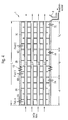
- the self-cleaning exhaust filter 1 for filtering out dirt particles on a plurality of tubes 2 through which each of the supersaturated exhaust air flows in the longitudinal direction of the exhaust filter 1 therethrough.
- the tubes 2 extend within at least one turning chamber 3, through which flows a fluid (for example a gas or liquid) outside the tubes 2 with an adjustable mass flow amount (m A o ) for cooling the exhaust air flowing through the tubes 2.
- the turning chamber 3 of the exhaust filter 1 is preferably cylindrical and has, for example, a diameter D of about 500 mm.
- the length L of the turning chamber 3 depends on the respective application or on the degree of soiling and the temperature T of the exhaust air A.
- the longitudinally extending tubes 2 are welded and rolled in end plates 4A, 4B at the front and rear of the exhaust air filter 1.
- the end plates 4A, 4B have, for example, a wall thickness of 1.5 by 2 cm.
- the tubes 2 have at the in FIG. 1 illustrated embodiment has a diameter of about 20 mm and have a distance of about 100 mm from each other.
- the turning chamber 3 contains turning plates 5-1, 5-2, 5-3, 5-4, so that the fluid F flowing in at an inlet 6 of the turning chamber 3 flows meandering past the tubes 2 until it reaches an outlet 7 of the turning chamber 3 ,
- the inserts 5-i for example, have a thickness of about 1 mm and are preferably made of stainless steel. The distance between the inserts 5-i is for example about 40 mm.
- the thickness of the tube walls of the tubes 2-i is for example 1 mm, the tubes 2-i preferably also made of stainless steel.
- exhaust filter 1 can be mounted in any position, ie as in FIG. 1 represented horizontally, but also vertically or at any angle of inclination relative to the earth's surface.
- the hot exhaust air A which is supersaturated with water vapor, meets at an adjustable mass flow rate m A o and with a certain temperature T A , for example 90 ° C to 100 ° C on the face plate 4A of the exhaust filter 1 and then flows through the tubes 2- through it.
- a cooling fluid F meandering through the turning chamber 3, wherein the fluid F is heated and the exhaust air A cools.
- the water vapor contained in the exhaust air A condenses within the tubes 2 at a migrating dew point TP (x), ie at a dew point TP whose position x changes within the tubes 2.
- the position of the migrating dew point TP along the longitudinal direction of the exhaust filter 1 changes depending on a mass flow difference ⁇ m ° between the mass flow amount m A o of the exhaust air A and a mass flow amount m F o of the fluid F.
- the condensed water absorbs the contained in the exhaust air A. Dirt particles, such as textile fluff, wax particles and other dirt particles and simultaneously cleans the tubes 2-i on the inside.
- the tubes 2 running in the longitudinal direction of the exhaust filter 1 are arranged inclined. Due to the inclination of the tubes 2 and the exhaust air flow through the tubes, the condensed water which forms in the tubes 2 at the tube inner walls and which collects inside the tubes 2 below, flow out of the tubes 2-i and collected for example by a funnel 8 become.
- the tubes are parallel to the outer wall the exhaust filter without inclination, so that only the exhaust air flow moves the collected condensation out of the tubes.
- FIG. 2 When passing through a tube 2-1 of the exhaust filter 1, the water-supersaturated exhaust air A cools down until the water vapor contained in the exhaust air A condenses at a dew point TP to condensate.
- the position of the dew point TP depends on a mass flow difference ⁇ m ° between the mass flow rate m A o of the exhaust air and a mass flow amount m F o of the fluid 2 flowing around the tubes F. If the mass flow rate ⁇ m o of the water-supersaturated exhaust air A is constant, the position x of the dew point TP depends solely on the mass flow rate m o F of the fluid F.
- both the mass flow rate m A o of the water-supersaturated exhaust air A and the mass flow rate m o F of the fluid F are adjustable.
- the position of the dew point TP in the exhaust air filter 1 according to the invention can also be adjusted by adjusting the mass flow rates, in particular the fluid F flowing around.
- the condensation or condensation as it forms on the inside of the tubes 2-i, absorbs the dirt particles contained in the exhaust air A and collects on the underside of the respective tube 2-i.
- the inside of the tubes 2-i is also cleaned. Dirt particles, such as textile fluff, which are deposited on the inside of the tubes 2-i are caused by the migrating dew points TP (x), ie by the condensation formed, dissolved and flow off together with the condensed water.
- the mass flow m ° F of the flowing fluid F periodically changed so that the dew point TP also periodically between the two end faces 4A, 4B of the exhaust filter 1 back and forth and so the tubes 2-i along its entire length L inside of dirt particles cleans.
- the meandering fluid F flowing through the turning chamber 3 is strongly heated by the hot exhaust air A inside the tubes 2-i, so that the temperature T F 'of the fluid F at the outlet 7 is higher than the temperature T F ' of the fluid F at the Inlet 6.
- the heating of the fluid F in the inventive self-cleaning drain filter 1 is used for energy recovery or energy recycling.
- FIG. 3 shows a possible embodiment of a cleaning system 9 according to the invention, which contains the self-cleaning exhaust filter 1 according to the invention.
- the textile cleaning installation 9 has a textile washing installation 10, in which any textiles are washed using chemicals, the washed textiles being fed to a textile ironing machine 11.
- the textiles are pressed and ironed, with water-supersaturated exhaust air A, which contains a large amount of textile fluff, waxes and other dirt particles, is discharged.
- This hot exhaust air A is fed to the self-cleaning exhaust filter 1.
- the fluid F for cooling the hot exhaust air A liquor discharged from an end portion of the fabric washing plant 10 is used in the textile washing machine 9.
- FIG. 3 illustrated textile cleaning system 9 has two recycling mechanisms, namely on the one hand energy recycling due to the heating of the liquor and on the other hand water recycling by recovery of condensed water for the fabric washing 10.
- the environmental impact is greatly reduced by filtering out the textile fluff from the hot exhaust air ,
- FIG. 4 shows a further embodiment of the inventive self-cleaning exhaust filter 1.
- the exhaust air filter 1 has three turning chambers 3A, 3B, 3C through which different fluids F A , F B , F C flow, respectively.
- the tubes 2-i extend through the three turning chambers 3A, 3B, 3C.
- the turning chambers 3A, 3B, 3C may have the same or different lengths depending on the application.
- the flowing through fluids F A , F B , F C can be formed by different or by the same gases or liquids.
- the turning chamber 3C has a Faltenbalk 13, which is provided to compensate for thermal expansion of the tubes 2-i.
- each turning chamber 3A, 3B, 3C may have its own folding beam 13.
- various turning chambers 3A, 3B, 3C can be connected to one another by mechanical connecting elements.
- the exhaust filter 1 is modular in structure by several turning chambers 3-i are mechanically connected to each other, ie the tubes 2-i are not as in in FIG. 4 illustrated embodiment throughout the entire exhaust filter 1, but each turning chamber 3-i has its own tubes 2-i, which are then assembled into a total tube.
- a modular design allows adjustment of the total length L of the exhaust filter 1 by selecting the number of serially connected turning chambers 3 according to the requirements of the application.
- FIG. 5 shows an application example for the in FIG. 4 shown exhaust filter 1 with three turning chambers 3A, 3B, 3C.
- a textile washing installation 10 within the textile cleaning installation 9 has a plurality of chambers 10-i for washing in, clear-washing and rinsing the textiles.
- a chamber 10-8 the liquor used in cleaning the textiles is removed and freed by a textile lint filter 12 of textile fluff.
- a portion of the filtered liquor is supplied to the fabric washing installation 10 for washing in a first chamber 10-1 and another portion of the lint removed from the lint is supplied as fluid to an inlet 6A of the first turning chamber 3A of the exhaust filter 1. Due to the flowing hot air A, the lye heated and discharged at the outlet 7A of the first turning chamber 3A heated.
- the heated liquor flows via a line 14 to a plate heat exchanger 15 through the plate heat exchanger 15, the already heated liquor 14 is heated again and passes as a highly heated liquor via a line 16 to the washing chamber 10-7 of the fabric washing system 10.
- the first turning chamber 3A of the self-cleaning exhaust filter 1 supplied fluid F consists of liquor, which is discharged from the fabric washing system 10 to the self-cleaning drain filter 1 and heated by the self-cleaning exhaust filter 1 back to the fabric washing system 10.
- the textiles washed by the textile washing plant 10 are fed to a dewatering press 17 which presses the textiles, wherein the pressed-out water or the press water is fed via a line 18 together with the condensed water formed by the exhaust filter 1 to a further textile lint filter 19.
- the filtered press and condensation water is fed via a water pipe 20 to a switch 21.
- This is the output side connected via a line 22 to the washing chamber 10-10 of the textile washing system 10.
- the washing chamber 10-10 can be supplied with the lint-free condensing and pressing water or heated fresh water which is discharged via a line 23 from an outlet 7B of the second turning chamber 3B of the self-cleaning exhaust air filter 1 according to the invention.
- the 5 illustrated embodiment receives the turning chamber 3B of the exhaust filter 1 as cooling fluid at the inlet 6B fresh water, for example, from a water network.
- the fresh water is heated by the hot exhaust air A and can additionally or alternatively to the lint removed dewatering and condensation of the fabric washing system 10 are supplied.
- the third turning chamber 3C of the exhaust filter 1 contains as fluid return water a heating system 24, for example, a floor heating. At the outlet 7C, the heated supply water is returned to the heater 24 via a line 25. The condensate discharged to the exhaust filter 1 passes through a line 26 to the textile lint filter 19 and is thus recycled into the washing process.
- the pressed textiles delivered by the textile washing installation 10 are fed to the textile ironing machine or defect 11.
- the textile ironing machine 11 or lack contains various rollers for ironing the textiles. This creates on the one hand a so-called lack exhaust air or water-oversaturated exhaust air A, which is contaminated with dirt particles, especially with textile fluff, and on the other pure condensate or water, which is fed via a line 27 to a steam separator 28.
- the steam separator 28 is connected on the output side via a line 29 to the plate heat exchanger 15, which additionally heats the liquor already heated by the first turning chamber 3A.
- the water supersaturated exhaust air A is generated by the textile ironing machine 11 and supplied via a line 30 to the exhaust filter 1 according to the invention and flows through the tubes 2-i therethrough, wherein it cools.
- the cooled and freed of textile fluff and other dirt particles exhaust air A is then released to the environment.
- the water discharged from the plate heat exchanger 15 is collected in a container 31.
- textile cleaning system 9 has three energy recycling circuits.
- a first turning chamber 3A of the drain filter 1 the discharged from the fabric washing system 11 liquor is heated.
- the second turning chamber 3 B of the exhaust filter 1 is supplied fresh water is through the hot exhaust air A is heated and supplied to the textile washing system 10.
- the return water coming from the heater 24 is heated by the third turning chamber 3C.
- the feeds 6A, 6B, 6C of the turning chamber 3A, 3B, 3C supplied in a switchable cleaning mode another cleaning fluid whose mass flow is selectively changed for the cleaning of the exhaust filter 1 to shift the dew point TP.
- the exhaust air discharged from the defect 11 is delivered to the self-cleaning exhaust air filter 1 in a volume flow of about 4,200 m 3 / h, wherein the temperature T A of the exhaust air A is about 100 ° C.
- the exhaust air contains a mass of water mass of 300 to 400 kg / h.
- the liquor supplied to the first turning chamber 3A has an inlet temperature of about 75 ° C and is warmed by the first turning chamber 3A and the plate heat exchanger 15 to the required 90 ° C for the washing process.
- the first turning chamber 3A become an exhaust air flow deprived of about 23 kW of power. At a water volume flow of 300 l / h, this corresponds to heating the water from 75 to 81.8 ° C. This energy is supplied to the lye stream, which consists mainly of water.
- fresh water is heated.
- the fresh water is fed into the heat exchanger at a feed temperature of the utility, this temperature being around 10 ° C.
- the heated fresh water is discharged at a temperature of about 60 ° C.
- the return water of the heater 24 is heated.
- the return temperature in winter is about 6 ° C and in summer about 12 ° C, the water is heated by the third turning chamber 3C to a flow temperature of 60 ° C.
- the temperature T of the discharged from the textile ironing machine 11 hot exhaust air A falls when passing through the self-cleaning exhaust filter 1 from about 100 ° C to about 60 ° C from.
- the self-cleaning exhaust filter 1 serves on the one hand to filter out dirt particles and on the other hand as a heat exchanger for the recovery of energy.
Abstract
Description
Die Erfindung betrifft ein selbstreinigendes Abluftfilter und ein Verfahren zum Herausfiltern von Schmutzpartikeln, die in einer wasserübersättigten Abluft enthalten sind, wobei gleichzeitig Energie gewonnen wird.The invention relates to a self-cleaning exhaust filter and a method for filtering out dirt particles contained in a water-supersaturated exhaust air, wherein at the same time energy is recovered.
Textilwaschanlagen weisen Textilbügelmaschinen auf, die große Mengen an wasserübersättigter Abluft erzeugen. Bei herkömmlichen Waschanlagen wird diese wasserübersättigte und verschmutzte Abluft ungefiltert und ohne Energie-Recycling an die Umgebung abgegeben wird. In einer Textilwaschanlage zum Waschen von Textilien werden die gewaschenen Textilien einer Textilbügelmaschine zugeführt, welche die gewaschenen Textilien presst und bügelt. Dabei entsteht einerseits Pressenwasser und andererseits wasserübersättigte Mangelabluft, die einen hohen Anteil an Textilflusen sowie Anteile der beim Waschvorgang verwendeten Wachse, Tenside und sonstige Schmutzpartikel enthält. Wird die wassergesättigte Mangelabluft an den Kühlrippen eines herkömmlichen Wärmetauschers vorbeigeführt, lagern sich an den Kühlrippen die Textilflusen oder sonstige Schmutzpartikel ab und verdrecken die Kühlrippen. Hierdurch steigt der Luftwiderstand des Wärmetauschers gegenüber dem zugeführten Luftstrom an, sodass es zu einem Staueffekt kommt und die Leistung der Textilbügelmaschine abnimmt.Textile washing systems have textile ironing machines which generate large quantities of water-oversaturated exhaust air. In conventional car washes this water-supersaturated and polluted air is discharged unfiltered and without energy recycling to the environment. In a textile washing machine for washing textiles, the washed textiles are fed to a textile ironing machine which presses and irons the washed textiles. This produces on the one hand press water and on the other hand water-oversaturated deficient exhaust air containing a high proportion of textile fluff and shares of wax used in the washing process, surfactants and other dirt particles. If the water-saturated deficient exhaust air passes the cooling fins of a conventional heat exchanger, the textile fluff or other dirt particles deposit on the cooling fins and corrode the cooling fins. As a result, the air resistance of the heat exchanger against the supplied air flow increases, so there is a jamming effect and decreases the performance of the textile ironing machine.
Bei derartigen Waschanlagen nach dem Stand der Technik sind daher herkömmliche Wärmetauscher zum Energie-Recycling ungeeignet. Bei herkömmlichen Waschanlagen wird deshalb die wasserübersättigte Abluft der Waschanlage, die stark mit Schmutzpartikeln belastet ist, ungefiltert und ohne Energie-Recycling an die Umgebung abgegeben.In such prior art washers, therefore, conventional heat exchangers are unsuitable for energy recycling. In conventional washing systems, therefore, the water-oversaturated exhaust air of the washing system, which is heavily contaminated with dirt particles, unfiltered and discharged without energy recycling to the environment.
Es ist eine Aufgabe der vorliegenden Erfindung, ein Abluftfilter und ein Verfahren zum Herausfiltern von Schmutzpartikeln, die in einer wasserübersättigten Abluft enthalten sind, zu schaffen, welche die in der Abluft abgegebene Energie zumindest teilweise wiedergewinnt.It is an object of the present invention to provide an exhaust filter and a method of filtering out particulate matter contained in a water-supersaturated exhaust air which at least partially recovers the energy released in the exhaust air.
Diese Aufgabe wird erfindungsgemäß durch ein selbstreinigendes Abluftfilter mit den im Patentanspruch 1 angegebenen Merkmalen gelöst.This object is achieved by a self-cleaning exhaust filter with the features specified in
Die Erfindung schafft ein selbstreinigendes Abluftfilter zum Herausfiltern von Schmutzpartikeln, die in einer wasserübersättigten Abluft enthalten sind, wobei das Abluftfilter aufweist:
- mehrere Röhren, durch welche die wasserübersättigte Abluft in einer Längsrichtung des Abluftfilters mit einer einstellbaren Massenstrommenge hindurchströmt, und
- mindestens einer Wendekammer, durch die ein Fluid außen an den Röhren des Abluftfilters mit einer einstellbaren Massenstrommenge zum Abkühlen der durch die Röhren hindurchströmenden Abluft vorbeiströmt,
- wobei ein in der Abluft enthaltener Wasserdampf innerhalb der Röhren an einem wandernden Taupunkt zu Wasser kondensiert, und
- wobei sich die Lage des wandernden Taupunktes entlang der Längsrichtung des Abluftfilters in Abhängigkeit von einer Massenstrommengendifferenz Δm° zwischen der Massenstrommenge der Abluft und einer Massenstrommenge des Fluids verändert und das kondensierte Wasser die in der Abluft enthaltenen Schmutzpartikel aufnimmt und die Röhren innen reinigt.
- a plurality of tubes through which the water supersaturated exhaust air flows in a longitudinal direction of the exhaust filter with an adjustable mass flow, and
- at least one turning chamber through which a fluid flows outside the tubes of the exhaust filter with an adjustable mass flow amount for cooling the exhaust air flowing through the tubes,
- wherein a water vapor contained in the exhaust air condenses to water within the tubes at a migratory dew point, and
- wherein the position of the migrating dew point along the longitudinal direction of the exhaust filter changes depending on a mass flow difference Δm ° between the mass flow amount of the exhaust air and a mass flow amount of the fluid and the condensed water absorbs the dirt particles contained in the exhaust air and cleans the tubes inside.
Das erfindungsgemäße selbstreinigende Abluftfilter hat als einen Vorteil, dass es sehr robust gegenüber Verschmutzungen ist und somit eine lange Betriebszeit aufweist.The self-cleaning exhaust air filter according to the invention has as an advantage that it is very robust against contamination and thus has a long operating time.
Ein weiterer Vorteil des erfindungsgemäßen selbstreinigenden Abluftfilters besteht darin, dass es die in der gesättigten Abluft enthaltenen Schmutzpartikel filtert und somit die Umweltbelastung durch die wasserübersättigte Abluft stark reduziert.Another advantage of the self-cleaning exhaust air filter according to the invention is that it filters the dirt particles contained in the saturated exhaust air and thus greatly reduces the environmental impact of the water-saturated exhaust air.
Ein weiterer Vorteil des erfindungsgemäßen selbstreinigenden Abluftfilters besteht darin, dass das Fluid durch die Abluft zur Energiegewinnung erwärmt wird.Another advantage of the self-cleaning exhaust air filter according to the invention is that the fluid is heated by the exhaust air for energy.
Bei einer Ausführungsform des erfindungsgemäßen selbstreinigenden Abluftfilters verlaufen die Röhren in Längsrichtung ohne Neigung parallel zu einer Außenwandung des Abluftfilters.In one embodiment of the self-cleaning exhaust air filter according to the invention, the tubes extend in the longitudinal direction without inclination parallel to an outer wall of the exhaust filter.
Bei einer alternativen Ausführungsform des erfindungsgemäßen selbstreinigenden Abluftfilters sind die in Längsrichtung des Abluftfilters verlaufenden Röhren derart geneigt angeordnet, dass sich das Kondenswasser, welches innerhalb der Röhren auf den Röhreninnenwandungen kondensiert, sich unten innerhalb der Röhren sammelt und aus den Röhren abfließt.In an alternative embodiment of the self-cleaning exhaust filter according to the invention, extending in the longitudinal direction of the exhaust filter tubes are arranged inclined so that the condensation, which condenses within the tubes on the tube inner walls, collects down inside the tubes and flows out of the tubes.
Bei einer weiteren Ausführungsform des erfindungsgemäßen selbstreinigenden Abluftfilters weist die Wendekammer mehrere quer zu der Längsrichtung des Abluftfilters angeordnete Umlenkwandungen auf, sodass das Fluid mäanderförmig außen an den Röhren quer zu der Längsrichtung des Abluftfilters vorbeiströmt.In a further embodiment of the self-cleaning exhaust air filter according to the invention, the turning chamber has a plurality of deflecting walls arranged transversely to the longitudinal direction of the exhaust air filter, so that the fluid flows meandering outside the pipes transversely to the longitudinal direction of the exhaust air filter.
Bei einer Ausführungsform des erfindungsgemäßen selbstreinigenden Abluftfilters wird die heiße Abluft von einer Textilbügelmaschine an das selbstreinigende Abluftfilter abgegeben.In one embodiment of the self-cleaning exhaust air filter according to the invention, the hot exhaust air is discharged from a textile ironing machine to the self-cleaning exhaust filter.
Bei einer Ausführungsform des erfindungsgemäßen selbstreinigenden Abluftfilters weist die heiße Abluft der Textilbügelmaschine eine Temperatur von 90°C bis 100°C auf.In one embodiment of the self-cleaning exhaust air filter according to the invention, the hot exhaust air of the textile ironing machine has a temperature of 90 ° C to 100 ° C.
Bei einer Ausführungsform des erfindungsgemäßen selbstreinigenden Abluftfilters werden die in der Abluft der Textilbügelmaschine enthaltenen Textilflusen, welche durch das kondensierte Wasser aufgenommen werden, aus dem gesammelten Kondenswasser des selbstreinigenden Abluftfilters durch ein weiteres Textilflusenfilter herausgefiltert.In one embodiment of the self-cleaning exhaust air filter according to the invention, the textile fluff contained in the exhaust air of the textile ironing machine, which are absorbed by the condensed water, filtered out of the collected condensed water of the self-cleaning exhaust filter by another textile lint filter.
Bei einer Ausführungsform des erfindungsgemäßen selbstreinigenden Abluftfilters ist das Fluid ein Gas oder eine Flüssigkeit.In one embodiment of the self-cleaning exhaust air filter according to the invention, the fluid is a gas or a liquid.
Bei einer Ausführungsform des erfindungsgemäßen selbstreinigenden Abluftfilters weist der selbstreinigende Abluftfilter mehrere Wendekammern auf, welchen jeweils ein zugehöriges Fluid separat zugeführt wird.In one embodiment of the self-cleaning exhaust air filter according to the invention, the self-cleaning exhaust filter has a plurality of turning chambers, to each of which an associated fluid is supplied separately.
Bei einer Ausführungsform des erfindungsgemäßen selbstreinigenden Abluftfilters wird das der Wendekammer des selbstreinigenden Abluftfilters zugeführte Fluid durch das selbstreinigende Abluftfilter erwärmt abgegeben.In one embodiment of the self-cleaning exhaust air filter according to the invention, the fluid supplied to the turning chamber of the self-cleaning exhaust air filter is discharged heated by the self-cleaning exhaust air filter.
Bei einer Ausführungsform des erfindungsgemäßen selbstreinigenden Abluftfilters besteht das einer Wendekammer des selbstreinigende Abluftfilters zugeführte Fluid aus einer Lauge, die von einer Textilwaschanlage an das selbstreinigende Abluftfilter abgegeben wird und die von dem selbstreinigenden Abluftfilter erwärmt an die Textilwaschanlage zurückgeführt wird.In one embodiment of the self-cleaning exhaust air filter according to the invention, the fluid supplied to a reversing chamber of the self-cleaning exhaust air filter consists of a liquor, which from a textile washing system to the self-cleaning exhaust air filter is discharged and heated by the self-cleaning exhaust air filter is returned to the textile washing system.
Bei einer Ausführungsform des erfindungsgemäßen selbstreinigenden Abluftfilters besteht das einer weiteren Wendekammer des selbstreinigenden Abluftfilters zugeführte Fluid aus Wasser, welches das durch das Textilflusenfilter gefilterte Kondenswasser des selbstreinigenden Abluftfilters enthält.In one embodiment of the self-cleaning exhaust air filter according to the invention, the fluid supplied to a further turning chamber of the self-cleaning exhaust air filter consists of water which contains the condensed water filtered by the textile lint filter of the self-cleaning exhaust air filter.
Bei einer Ausführungsform des erfindungsgemäßen selbstreinigenden Abluftfilters ist das einer weiteren Wendekammer des selbstreinigenden Abluftfilters zugeführte Fluid Wasser, das für eine Heizung erwärmt wird.In one embodiment of the self-cleaning exhaust air filter according to the invention, the fluid supplied to a further turning chamber of the self-cleaning exhaust air filter is water which is heated for heating.
Bei einer Ausführungsform des erfindungsgemäßen selbstreinigenden Abluftfilters weisen die Röhren einen Durchmesser von etwa 20 mm auf.In one embodiment of the self-cleaning exhaust filter according to the invention, the tubes have a diameter of about 20 mm.
Bei einer Ausführungsform des erfindungsgemäßen selbstreinigenden Abluftfilters sind die Röhren aus Edelstahl hergestellt.In one embodiment of the self-cleaning exhaust filter according to the invention, the tubes are made of stainless steel.
Bei einer Ausführungsform des erfindungsgemäßen selbstreinigenden Abluftfilters weisen die Röhrenwandungen der jeweiligen Röhren eine Dicke von etwa 1 mm auf.In one embodiment of the self-cleaning exhaust air filter according to the invention, the tube walls of the respective tubes have a thickness of about 1 mm.
Bei einer Ausführungsform des erfindungsgemäßen selbstreinigenden Abluftfilters weist mindestens eine Wendekammer einen Faltenbalk zum Ausgleich einer Wärmeausdehnung der Röhren auf.In one embodiment of the self-cleaning exhaust air filter according to the invention, at least one turning chamber has a bellows to compensate for thermal expansion of the tubes.
Die Erfindung schafft ferner eine Textilreinigungsanlage mit:
- einer Textilwaschanlage zum Waschen von Textilien mittels eines Fluids,
- einer Textilbügelmaschine zum Bügeln der von der Textilwaschanlage gewaschenen Textilien, wobei die Textilbügelmaschine wasserübersättigte Abluft abgibt, und
- einem selbstreinigenden Abluftfilter zum Herausfiltern von Schmutzpartikeln, die in einer wasserübersättigten Abluft enthalten sind, wobei das Abluftfilter aufweist:
- mehrere Röhren, durch welche die wasserübersättigte Abluft in einer Längsrichtung des Abluftfilters mit einer einstellbaren Massenstrommenge hindurchströmt, und
- mindestens einer Wendekammer, durch die ein Fluid außen an den Röhren des Abluftfilters mit einer einstellbaren Massenstrommenge zum Abkühlen der durch die Röhren hindurchströmenden Abluft vorbeiströmt,
- wobei ein in der Abluft enthaltener wasserdampf innerhalb der Röhren an einem wandernden Taupunkt zu Wasser kondensiert, und
- wobei sich die Lage des wandernden Taupunktes entlang der Längsrichtung des Abluftfilters in Abhängigkeit von einer Massenstrommengendifferenz Δm° zwischen der Massenstrommenge der Abluft und einer Massenstrommenge des Fluids verändert und das kondensierte Wasser die in der Abluft enthaltenen Schmutzpartikel aufnimmt und die Röhren innen reinigt.
- a textile washing machine for washing textiles by means of a fluid,
- a textile ironing machine for ironing the washed by the textile washing machine textiles, the textile ironing machine emits water-supersaturated exhaust air, and
- a self-cleaning exhaust air filter for filtering out dirt particles contained in a water-supersaturated exhaust air, wherein the exhaust air filter comprises:
- a plurality of tubes through which the water supersaturated exhaust air flows in a longitudinal direction of the exhaust filter with an adjustable mass flow, and
- at least one turning chamber through which a fluid flows outside the tubes of the exhaust filter with an adjustable mass flow amount for cooling the exhaust air flowing through the tubes,
- wherein a water vapor contained in the exhaust air condenses to water within the tubes at a migratory dew point, and
- wherein the position of the migrating dew point along the longitudinal direction of the exhaust filter changes depending on a mass flow difference Δm ° between the mass flow amount of the exhaust air and a mass flow amount of the fluid and the condensed water absorbs the dirt particles contained in the exhaust air and cleans the tubes inside.
Bei einer Ausführungsform der erfindungsgemäßen Textilreinigungsanlage wird das von dem selbstreinigenden Abluftfilter gebildete Kondenswasser durch ein Textilflusenfilter an die Textilwaschanlage zum Recyceln von Wasser zurückgeführt.In one embodiment of the textile cleaning system according to the invention, the condensation water formed by the self-cleaning exhaust air filter is recycled by a textile lint filter to the textile washing plant for recycling water.
Die Erfindung schafft ferner ein Verfahren zum Filtern von Schmutzpartikeln aus einer wasserübersättigten Abluft, wobei die wasserübersättigte Abluft mit einer einstellbaren Massenstrommenge durch Röhren strömt, an denen außen ein Fluid zum Abkühlen der durch die Röhren hindurchströmenden Abluft derart vorbeiströmt, dass ein in der Abluft enthaltener Wasserdampf innerhalb der Röhren zu Wasser an einem wandernden Taupunkt kondensiert, dessen Lage sich in Längsrichtung der Röhren in Abhängigkeit von einer Massenstrommengendifferenz zwischen der Massenstrommenge der Abluft und einer Massenstrommenge des Fuids verändert, wobei das an dem wandernden Taupunkt kondensierte Wasser die in der Abluft enthaltenen Schmutzpartikel aufnimmt und die Röhren innen reinigt.The invention further provides a method of filtering debris from water-supersaturated exhaust air, wherein the water-supersaturated exhaust air flows through tubes at an adjustable mass flow rate past which a fluid for cooling the exhaust air passing through the tubes flows past such that a water vapor contained in the exhaust air condenses within the tubes to water at a migratory dew point, the position of which changes in the longitudinal direction of the tubes in dependence on a mass flow difference between the mass flow rate of the exhaust air and a mass flow amount of Fuids, wherein the condensed water at the migrating dew point absorbs the dirt particles contained in the exhaust air and clean the tubes inside.
Im Weiteren werden Ausführungsformen des erfindungsgemäßen selbstreinigenden Abluftfilters und der erfindungsgemäßen Textilwaschanlage unter Bezugnahme auf die beigefügten Figuren zur Erläuterung erfindungswesentlicher Merkmale näher beschrieben.In the following, embodiments of the self-cleaning exhaust air filter according to the invention and of the textile washing installation according to the invention will be described in more detail with reference to the attached figures to explain features essential to the invention.
Es zeigen:
- Figur 1:
- eine Ausführungsform des erfindungsgemäßen selbstreinigenden Abluftfilters;
- Figur 2:
- ein Diagramm zur Erläuterung der Funktionsweise des erfindungsgemäßen selbstreinigenden Abluftfilters;
- Figur 3:
- ein Blockschaltbild einer Textilreinigungsanlage, welches ein selbstreinigendes Abluftfilter gemäß der Erfindung aufweist;
- Figur 4:
- eine weitere Ausführungsform des erfindungsgemäßen selbstreinigenden Abluftfilters;
- Figur 5:
- eine Ausführungsform der Textilreinigungsanlage, welches das in
Figur 4 dargestellte selbstreinigende Abluftfilter aufweist.
- FIG. 1:
- an embodiment of the self-cleaning exhaust filter according to the invention;
- FIG. 2:
- a diagram for explaining the operation of the self-cleaning exhaust filter according to the invention;
- FIG. 3:
- a block diagram of a textile cleaning system, which has a self-cleaning exhaust filter according to the invention;
- FIG. 4:
- a further embodiment of the self-cleaning exhaust filter according to the invention;
- FIG. 5:
- an embodiment of the textile cleaning system, which in
FIG. 4 having shown self-cleaning exhaust filter.
Wie man aus
Die heiße Abluft A, welche mit Wasserdampf übersättigt ist, trifft bei einer einstellbaren Massenstrommenge mA o und mit einer bestimmten Temperatur TA, beispielsweise 90°C bis 100°C auf die Stirnplatte 4A des Abluftfilters 1 und strömt dann durch die Röhren 2-i hindurch. Gleichzeitig fließt an der Außenseite der Röhren 2 ein kühlendes Fluid F mäanderförmig durch die Wendekammer 3, wobei sich das Fluid F erwärmt und die Abluft A abkühlt. Dabei kondensiert der in der Abluft A enthaltene Wasserdampf innerhalb der Röhren 2 an einem wandernden Taupunkt TP(x), d. h. an einem Taupunkt TP dessen Lage x sich innerhalb der Röhren 2 verändert. Die Lage des wandernden Taupunkts TP entlang der Längsrichtung des Abluftfilters 1 ändert sich in Abhängigkeit von einer Massenstrommengendifferenz Δm° zwischen der Massenstrommenge mA o der Abluft A und einer Massenstrommenge mF o des Fluids F. Das kondensierte Wasser nimmt die in der Abluft A enthaltenen Schmutzpartikel, beispielsweise Textilflusen, Wachspartikel und sonstige Schmutzpartikel auf und reinigt gleichzeitig die Röhren 2-i auf der Innenseite.The hot exhaust air A, which is supersaturated with water vapor, meets at an adjustable mass flow rate m A o and with a certain temperature T A , for example 90 ° C to 100 ° C on the
Bei einer möglichen Ausführungsform des erfindungsgemäßen selbstreinigenden Abluftfilters 1 sind die in Längsrichtung des Abluftfilters 1 verlaufenden Röhren 2 geneigt angeordnet. Durch die Neigung der Röhren 2 sowie des Abluftstroms durch die Röhren kann das Kondenswasser, welches sich in den Röhren 2 an den Röhreninnenwandungen bildet und welches sich innerhalb der Röhren 2 unten sammelt, aus den Röhren 2-i abfließen und beispielsweise durch einen Trichter 8 aufgefangen werden. Vorzugsweise verlaufen die Röhren parallel zu der Außenwandung des Abluftfilters ohne Neigung, sodass allein der Abluftstrom das gesammelte Kondenswasser aus den Röhren herausbewegt.In one possible embodiment of the self-cleaning
Das durch die Wendekammer 3 mäanderförmig hindurchströmende Fluid F wird durch die heiße Abluft A innerhalb der Röhren 2-i stark erwärmt, sodass die Temperatur TF ' des Fluids F an dem Auslass 7 höher ist als die Temperatur TF' des Fluids F an dem Einlass 6. Die Erwärmung des Fluids F bei dem erfindungsgemäßem selbstreinigenden Ablauffilters 1 wird zur Energierückgewinnung bzw. zum Energie-Recycling genutzt.The meandering fluid F flowing through the turning
Die in
In einer weiteren Ausführungsform des erfindungsgemäßen selbstreinigenden Abluftfilters 1 sind verschiedene Wendekammern 3A, 3B, 3C durch mechanische Verbindungselemente miteinander verbindbar. Bei dieser Ausführungsform ist der Abluftfilter 1 modular aufbaubar, indem mehrere Wendekammern 3-i miteinander mechanisch verbunden werden, d. h. die Röhren 2-i sind nicht wie bei der in
Eine Textilwaschanlage 10 innerhalb der Textilreinigungsanlage 9 weist mehrere Kammern 10-i zum Einwaschen, Klarwaschen und Spülen der Textilien auf. In einer Kammer 10-8 wird die beim Reinigen der Textilien verwendete Lauge abgeführt und durch ein Textilflusenfilter 12 von Textilienflusen befreit. Ein Teil der gefilterten Lauge wird in einer ersten Kammer 10-1 der Textilwaschanlage 10 zum Einwaschen zugeführt und ein anderer Teil der flusenbefreiten Lauge wird als Fluid einem Einlass 6A der ersten Wendekammer 3A des Abluftfilters 1 zugeführt. Durch die durchströmende heiße Abluft A wird die Lauge erwärmt und an dem Auslass 7A der ersten Wendekammer 3A erwärmt abgegeben. Bei der in
Die durch die Textilwaschanlage 10 gereinigten Textilien werden einer Entwässerungspresse 17 zugeführt, welche die Textilien presst, wobei das ausgepresste Wasser bzw. das Pressenwasser über eine Leitung 18 zusammen mit dem durch das Abluftfilter 1 gebildeten Kondenswasser einem weiteren Textilflusenfilter 19 zugeführt wird. Das gefilterte Pressen- und Kondenswasser wird über eine Wasserleitung 20 zu einem Umschalter 21 geführt. Dieser ist ausgangsseitig über eine Leitung 22 mit der Waschkammer 10-10 der Textilwaschanlage 10 verbunden. Mit dem Umschalter 21 kann der Waschkammer 10-10 einerseits das flusenbefreite Kondens- und Pressenwasser zugeführt werden oder erwärmtes Frischwasser, welches über eine Leitung 23 von einem Auslass 7B der zweiten Wendekammer 3B des erfindungsgemäßen selbstreinigenden Abluftfilters 1 abgegeben wird. Bei der in
Die dritte Wendekammer 3C des Abluftfilters 1 enthält als Fluid Rücklaufwasser einer Heizanlage 24, beispielsweise einer Fußbodenheizung. An dem Auslass 7C wird das erhitzte Vorlaufwasser an die Heizung 24 über eine Leitung 25 zurückgeführt. Das an das Abluftfilter 1 abgegebene Kondenswasser gelangt über eine Leitung 26 zu dem Textilflusenfilter 19 und wird somit in den Waschvorgang recycled.The
Die von der Textilwaschanlage 10 abgegebenen gepressten Textilien werden der Textilbügelmaschine bzw. Mangel 11 zugeführt. Die Textilbügelmaschine 11 bzw. Mangel enthält verschiedene Walzen zum Bügeln der Textilien. Dabei entsteht einerseits eine sogenannte Mangelabluft bzw. wasserübersättigte Abluft A, die mit Schmutzpartikeln, insbesondere mit Textilflusen, belastet ist und andererseits reines Kondensat bzw. Wasser, welches über eine Leitung 27 einem Dampftrenner 28 zugeführt wird. Der Dampftrenner 28 ist ausgangsseitig über eine Leitung 29 mit dem Plattenwärmetauscher 15 verbunden, welcher die durch die erste Wendekammer 3A bereits erwärmte Lauge zusätzlich erhitzt. Die wasserübersättigte Abluft A wird durch die Textilbügelmaschine 11 erzeugt und über eine Leitung 30 dem Abluftfilter 1 gemäß der Erfindung zugeführt und strömt durch dessen Röhren 2-i hindurch, wobei sie sich abkühlt. Die abgekühlte und von Textilflusen und sonstigen Schmutzpartikeln befreite Abluft A wird dann an die Umgebung abgegeben. Das von dem Plattenwärmetauscher 15 abgegebene Wasser wird in einem Behälter 31 gesammelt.The pressed textiles delivered by the
Die in
Neben dem Energie-Recycling wird bei der Textilreinigungsanlage 9 gemäß
Der erfindungsgemäße selbstreinigende Abluftfilter 1 filtert die mit Wachsen, Tensiden und Salzen belastet Brüdenabluft der Textilbügelmaschine 11. Durch Einstellung der Massenstrommenge mo F des kühlenden Fluids F, welches durch die Wendekammern 3 strömt oder durch Einstellung der Massenstrommenge mA o der zugeführten Abluft A kann zudem die Lage des Taupunkts TP innerhalb der Röhren 2 zur Selbstreinigung des Abluftfilters 1 eingestellt werden.By adjusting the mass flow M o F of the cooling fluid F, which flows through the turning
Bei einer weiteren möglichen Ausführungsform wird den Zuläufen 6A, 6B, 6C der Wendekammer 3A, 3B, 3C in einem umschaltbaren Reinigungsbetriebsmodus ein anderes Reinigungsfluid zugeführt, dessen Massenstrommenge gezielt für die Reinigung des Abluftfilters 1 zur Verschiebung des Taupunkts TP verändert wird.In another possible embodiment, the
Bei einer möglichen Ausführungsform der Textilreinigungsanlage 9 ist die von der Mangel 11 abgegebene Brüdenabluft in einem Volumenstrom von ca. 4.200 m3/h an das selbstreinigende Abluftfilter 1 abgegeben, wobei die Temperatur TA der Abluft A etwa 100°C beträgt. Die Abluft enthält dabei eine Wassermassenstrommenge von 300 bis 400 kg/h. Die der ersten Wendekammer 3A zugeführte Lauge weist eine Eintrittstemperatur von etwa 75°C auf und wird durch die erste Wendekammer 3A und den Plattenwärmetauscher 15 auf die benötigten 90°C für den Waschvorgang aufgewärmt. Der ersten Wendekammer 3A werden ein Abluftstrom von etwa 23 kW an Leistung entzogen. Bei einem Wasservolumenstrom von 300 l/h entspricht dies einer Erwärmung des Wassers von 75 auf 81,8°C. Diese Energie wird dem Laugenstrom, der hauptsächlich aus Wasser besteht, zugeführt.In one possible embodiment of the
In der zweiten Stufe 3B des Abluftfilters 1 wird Frischwasser erwärmt. Das Frischwasser wird mit einer Einspeisetemperatur des Versorgungsunternehmens in den Wärmetauscher eingespeist, wobei diese Temperatur bei etwa 10°C liegt. Das erwärmte Frischwasser wird mit einer Temperatur von etwa 60°C abgegeben.In the
In der dritten Stufe des Abluftfilters 1 wird das Rücklaufwasser der Heizung 24 erwärmt. Die Rücklauftemperatur beträgt im Winter etwa 6°C und im Sommer etwa 12°C, wobei das Wasser durch die dritte Wendekammer 3C auf eine Vorlauftemperatur von 60°C erwärmt wird.In the third stage of the
Die Temperatur T der von der Textilbügelmaschine 11 abgegebenen heißen Abluft A fällt beim Durchlaufen durch das selbstreinigende Abluftfilter 1 von etwa 100°C auf etwa 60°C ab.The temperature T of the discharged from the
Das erfindungsgemäße selbstreinigende Abluftfilter 1 dient einerseits zum Herausfiltern von Schmutzpartikeln und andererseits als Wärmetauscher zur Rückgewinnung von Energie.The self-cleaning
Claims (19)
wobei die in Längsrichtung des Abluftfilters (1) verlaufenden Röhren (2) derart geneigt angeordnet sind, dass das Kondenswasser, welches innerhalb der Röhren (2) auf den Röhreninnenwandungen kondensiert sich unten innerhalb der Röhren sammelt und aus den Röhren (2) abfließt, oder die durch die Röhren (2) hindurchströmende Abluft das sich unten innerhalb der Röhren (2) gesammelte Kondenswasser aus den Röhren (2) herausdrückt.Self-cleaning exhaust filter according to claim 1,
wherein the tubes (2) extending in the longitudinal direction of the exhaust filter (1) are inclined so that the condensed water condensing inside the tubes (2) on the tube inner walls collects down inside the tubes and flows out of the tubes (2), or through the tubes (2) passing through the exhaust air collected down inside the tubes (2) condensed water from the tubes (2).
wobei die Wendekammer mehrere quer zu der Längsrichtung des Abluftfilters (1) angeordnete Umlenkwandungen (5) aufweist, durch welche das Fluid mäanderförmig außen an den Röhren (5) quer zu der Längsrichtung des Abluftfilters (1) vorbeiströmt.Self-cleaning exhaust filter according to claim 1,
wherein the turning chamber has a plurality of deflecting walls (5) arranged transversely to the longitudinal direction of the exhaust air filter (1), through which the fluid flows meandering outside the tubes (5) transversely to the longitudinal direction of the exhaust air filter (1).
wobei die heiße Abluft von einer Textilbügelmaschine (11) an das selbstreinigende Abluftfilter (1) abgegeben wird.Self-cleaning exhaust filter according to claim 1,
wherein the hot exhaust air from a textile ironing machine (11) to the self-cleaning exhaust filter (1) is discharged.
wobei die heiße Abluft der Textilbügelmaschine (11) eine Temperatur von 90°C - 100°C aufweist.Self-cleaning exhaust filter according to claim 4,
wherein the hot exhaust air of the textile ironing machine (11) has a temperature of 90 ° C - 100 ° C.
wobei ein Textilflusenfilter (12) die in der Abluft der Textilbügelmaschine (11) enthaltenen Textilflusen, welche durch das kondensierte Wasser aufgenommen werden, aus dem gesammelten Kondenswasser des selbstreinigenden Abluftfilters (1) herausfiltert.Self-cleaning exhaust filter according to claim 4,
wherein a textile lint filter (12) in the exhaust air of the textile ironing machine (11) contained textile fluff, which are absorbed by the condensed water, from the collected condensed water of the self-cleaning exhaust filter (1) filters out.
wobei das Fluid ein Gas oder eine Flüssigkeit ist.Self-cleaning exhaust filter according to claim 1,
wherein the fluid is a gas or a liquid.
wobei das selbstreinigende Abluftfilter (1) mehrere Wendekammern (3) aufweist, denen jeweils ein zugehöriges Fluid separat zugeführt wird.Self-cleaning exhaust filter according to claim 1,
wherein the self-cleaning exhaust filter (1) has a plurality of turning chambers (3) to each of which an associated fluid is supplied separately.
wobei das in der Wendekammer (3) des selbstreinigenden Abluftfilters zugeführte Fluid durch das selbstreinigende Abluftfilter (1) erwärmt abgegeben wird.Self-cleaning exhaust filter according to claim 8,
wherein the fluid supplied in the turning chamber (3) of the self-cleaning exhaust air filter is discharged heated by the self-cleaning exhaust air filter (1).
wobei das einer Wendekammer (3) des selbstreinigenden Abluftfilters (1) zugeführte Fluid aus Lauge besteht, die von eine Textilwaschanlage (11) an das selbstreinigende Abluftfilter (1) abgegeben wird und die von dem selbstreinigenden Abluftfilter (1) erwärmt an die Textilwaschanlage (11) zurückgeführt wird.Self-cleaning exhaust filter according to claim 9,
wherein the fluid supplied to a turning chamber (3) of the self-cleaning exhaust air filter (1) consists of lye discharged from a textile washing plant (11) to the self-cleaning exhaust air filter (1) and heated by the self-cleaning exhaust air filter (1) to the textile washing plant (11 ) is returned.
wobei das einer weiteren Wendekammer (3) des selbstreinigenden Abluftfilters (1) zugeführte Fluid aus Wasser besteht, welches durch ein Textilflusenfilter (19) gefilterte Kondenswasser des selbstreinigenden Abluftfilters (1) enthält.Self-cleaning exhaust filter according to claim 8,
wherein the fluid supplied to a further turning chamber (3) of the self-cleaning exhaust air filter (1) consists of water which contains condensed water filtered by a textile lint filter (19) of the self-cleaning exhaust air filter (1).
wobei das einer weiteren Wendekammer (3) des selbstreinigenden Abluftfilters (1) zugeführte Fluid Wasser für eine Heizung ist.Self-cleaning exhaust filter according to claim 8,
wherein the fluid supplied to a further turning chamber (3) of the self-cleaning exhaust air filter (1) is water for heating.
wobei die Röhren (2) einen Durchmesser von etwa 20 mm aufweisen.Self-cleaning exhaust filter according to claim 1,
wherein the tubes (2) have a diameter of about 20 mm.
wobei die Röhren (2) aus Edelstahl hergestellt sind.Self-cleaning exhaust filter according to claim 1,
the tubes (2) are made of stainless steel.
wobei die Röhrenwandungen der jeweiligen Röhren (2) eine Dicke von etwa 1 mm aufweisen.Self-cleaning exhaust filter according to claim 1,
wherein the tube walls of the respective tubes (2) have a thickness of about 1 mm.
wobei die Wendekammer (3) einen Faltenbalk (13) zum Ausgleich einer Wärmeausdehnung der Röhren (2) aufweist.Self-cleaning exhaust filter according to claim 1,
wherein the turning chamber (3) has a Faltenbalk (13) to compensate for thermal expansion of the tubes (2).
wobei das von dem selbstreinigenden Abluftfilter (1) gebildete Kondenswasser durch ein Textilflusenfilter (19) gefiltert an die Textilwaschanlage (11A) zum Recycling von Wasser zurückgeführt wird.Textile cleaning system according to claim 17,
wherein the condensate formed by the self-cleaning exhaust filter (1) filtered by a textile lint filter (19) to the textile washing plant (11A) for recycling water is recycled.
wobei die wasserübersättigte Abluft mit einer einstellbaren Massenstrommenge (mA°) durch Röhren (2) strömt, an denen außen ein Fluid zum Abkühlen der durch die Röhren (2) hindurchströmenden Abluft derart vorbeiströmt,
dass ein in der Abluft enthaltener Wasserdampf innerhalb der Röhren (2) zu Wasser an einem wandernden Taupunkt (TP) kondensiert, dessen Lage sich in Längsrichtung der Röhren (2) in Abhängigkeit von einer Massenstrommengendifferenz (Δm°) zwischen der Massenstrommenge (mA°) der Abluft und einer Massenstrommenge (mF°) des Fluids verändert,
wobei das an dem wandernden Taupunkt (TP) kondensierte Wasser die in der Abluft enthaltenen Schmutzpartikel aufnimmt und die Röhren (2) innen reinigt.Method for filtering dirt particles from a water-oversaturated exhaust air,
wherein the water-supersaturated exhaust air flows at an adjustable mass flow rate (m A ° ) through tubes (2) on which outside a fluid for cooling the exhaust air flowing through the tubes (2) so flows,
in that a water vapor contained in the exhaust air inside the tubes (2) condenses to water at a migratory dew point (TP), the position of which is dependent on the length of the tubes (2) of a mass flow difference (Δm °) between the mass flow rate (m A ° ) of the exhaust air and a mass flow rate (m F ° ) of the fluid,
wherein the condensed at the migrating dew point (TP) water absorbs the dirt particles contained in the exhaust air and cleans the tubes (2) inside.
Applications Claiming Priority (1)
| Application Number | Priority Date | Filing Date | Title |
|---|---|---|---|
| DE200710004100 DE102007004100B4 (en) | 2007-01-26 | 2007-01-26 | Process for filtering dirt particles |
Publications (2)
| Publication Number | Publication Date |
|---|---|
| EP1955754A1 true EP1955754A1 (en) | 2008-08-13 |
| EP1955754B1 EP1955754B1 (en) | 2017-01-11 |
Family
ID=39272123
Family Applications (1)
| Application Number | Title | Priority Date | Filing Date |
|---|---|---|---|
| EP07121170.0A Not-in-force EP1955754B1 (en) | 2007-01-26 | 2007-11-21 | Device and method for filtering dirt particles |
Country Status (2)
| Country | Link |
|---|---|
| EP (1) | EP1955754B1 (en) |
| DE (1) | DE102007004100B4 (en) |
Cited By (3)
| Publication number | Priority date | Publication date | Assignee | Title |
|---|---|---|---|---|
| RU2537590C2 (en) * | 2013-02-12 | 2015-01-10 | Федеральное государственное бюджетное образовательное учреждение высшего профессионального образования "Воронежский государственный технический университет" | Method of steam supply to condensing chamber |
| RU2537495C2 (en) * | 2013-02-12 | 2015-01-10 | Федеральное государтсвенное бюджетное образовательное учреждение высшего профессионального образования "Воронежский государственный технический университет" | Air cleaner |
| RU2537587C2 (en) * | 2013-02-12 | 2015-01-10 | Федеральное государственное бюджетное образовательное учреждение высшего профессионального образования "Воронежский государственный технический университет" | Feed of steam into condensation chamber |
Families Citing this family (2)
| Publication number | Priority date | Publication date | Assignee | Title |
|---|---|---|---|---|
| DE102008054104A1 (en) * | 2008-10-31 | 2010-05-06 | Herbert Kannegiesser Gmbh | Method and device for treating the exhaust air from heated laundry machines |
| CN114797142B (en) * | 2022-03-22 | 2023-10-24 | 浙江三江化工新材料有限公司 | Ethylene oxide low pressure condensate aftertreatment system |
Citations (5)
| Publication number | Priority date | Publication date | Assignee | Title |
|---|---|---|---|---|
| DE1501620A1 (en) * | 1964-04-09 | 1969-06-26 | Grenobloise Etude Appl | Improvements from heat exchangers |
| DE3111680A1 (en) * | 1981-03-25 | 1982-10-14 | IGEFA Ing. Ges. für Elektrowärme-Fernwärme- und Abwärmetechnik mbH, 5900 Siegen | Process and apparatus for the recovery of heat in laundries |
| US4548262A (en) * | 1983-03-31 | 1985-10-22 | Hull Francis R | Condensing gas-to-gas heat exchanger |
| DE3528426A1 (en) * | 1985-08-08 | 1987-02-19 | Mederer Gmbh | PRESSURE RESOLUTION - CASTING HEATER |
| EP0444846A2 (en) * | 1990-02-27 | 1991-09-04 | Energiagazdálkodási Részvénytársaság | Heat exchanger apparatus, particularly for hybrid heat pumps operated with non-azeotropic work fluids |
Family Cites Families (2)
| Publication number | Priority date | Publication date | Assignee | Title |
|---|---|---|---|---|
| DD149883A3 (en) * | 1977-10-14 | 1981-08-05 | Konrad Michael | HEAT TRANSFER FOR HIGHER FLOW SPEEDS, ESPECIALLY FOR GASOFME MEDIA |
| DE3734388A1 (en) * | 1987-10-10 | 1989-04-20 | Sueddeutsche Kuehler Behr | METHOD AND DEVICE FOR SEPARATING CONDENSIBLE POLLUTANTS AND SOLID PARTICLES IN PROCESS AIR |
-
2007
- 2007-01-26 DE DE200710004100 patent/DE102007004100B4/en not_active Expired - Fee Related
- 2007-11-21 EP EP07121170.0A patent/EP1955754B1/en not_active Not-in-force
Patent Citations (5)
| Publication number | Priority date | Publication date | Assignee | Title |
|---|---|---|---|---|
| DE1501620A1 (en) * | 1964-04-09 | 1969-06-26 | Grenobloise Etude Appl | Improvements from heat exchangers |
| DE3111680A1 (en) * | 1981-03-25 | 1982-10-14 | IGEFA Ing. Ges. für Elektrowärme-Fernwärme- und Abwärmetechnik mbH, 5900 Siegen | Process and apparatus for the recovery of heat in laundries |
| US4548262A (en) * | 1983-03-31 | 1985-10-22 | Hull Francis R | Condensing gas-to-gas heat exchanger |
| DE3528426A1 (en) * | 1985-08-08 | 1987-02-19 | Mederer Gmbh | PRESSURE RESOLUTION - CASTING HEATER |
| EP0444846A2 (en) * | 1990-02-27 | 1991-09-04 | Energiagazdálkodási Részvénytársaság | Heat exchanger apparatus, particularly for hybrid heat pumps operated with non-azeotropic work fluids |
Cited By (3)
| Publication number | Priority date | Publication date | Assignee | Title |
|---|---|---|---|---|
| RU2537590C2 (en) * | 2013-02-12 | 2015-01-10 | Федеральное государственное бюджетное образовательное учреждение высшего профессионального образования "Воронежский государственный технический университет" | Method of steam supply to condensing chamber |
| RU2537495C2 (en) * | 2013-02-12 | 2015-01-10 | Федеральное государтсвенное бюджетное образовательное учреждение высшего профессионального образования "Воронежский государственный технический университет" | Air cleaner |
| RU2537587C2 (en) * | 2013-02-12 | 2015-01-10 | Федеральное государственное бюджетное образовательное учреждение высшего профессионального образования "Воронежский государственный технический университет" | Feed of steam into condensation chamber |
Also Published As
| Publication number | Publication date |
|---|---|
| EP1955754B1 (en) | 2017-01-11 |
| DE102007004100A1 (en) | 2008-08-07 |
| DE102007004100B4 (en) | 2011-12-29 |
Similar Documents
| Publication | Publication Date | Title |
|---|---|---|
| EP1955754B1 (en) | Device and method for filtering dirt particles | |
| EP2419559B1 (en) | Condensation dryer having a filter device | |
| EP2606172B1 (en) | Laundry treatment device having a screen holder and method for operating a laundry treatment device having a lint screen | |
| WO2010028992A1 (en) | Dryer having a lint filter and a cleaning device | |
| EP2606171B1 (en) | Laundry treatment device comprising a lint filter | |
| WO2015135801A1 (en) | Dryer with flushing device and lint receptacle, and method for operating same | |
| EP2122036A1 (en) | Method for the recovery of waste heat from heated launderette machines | |
| EP2182106B1 (en) | Method and device for preparing exhaust air from heated laundry machines | |
| WO2017089027A1 (en) | Operating a laundry drying device with a lint filter and a lint trap | |
| DE3507303A1 (en) | PLANT FOR TREATING AND PURIFYING POLLUTED GASES | |
| EP2157231A1 (en) | Domestic tumble drier and method for cleaning a component, in particular an evaporator of an evaporator device for such a drier | |
| EP3405610A1 (en) | Method for operating a drier with a heat pump and rinsing a heat exchanger and drier suitable therefor | |
| EP0548386B1 (en) | Method and device for cleaning the exhaust air of a drum laundry drier | |
| CH660417A5 (en) | DEVICE FOR RECOVERING HEAT FROM POLLUTED WASTE WATER. | |
| EP0302448A2 (en) | Purifying process for solvents and apparatus for carrying out this process | |
| DE102014200768A1 (en) | Apparatus and method for cleaning a arranged in a process air cycle of a dryer component and dryer with such a device | |
| EP3147404B1 (en) | Laundry drier with water supply | |
| EP0535348A1 (en) | Drier or washing and drying machine with a condensing device | |
| DE19601759A1 (en) | Exhaust air cleaner for e.g. a tenter frame | |
| DE4307608C2 (en) | Method and device for using energy from flue gases in coal-fired power plants | |
| DE102015107856B4 (en) | Dehumidifying device and dehumidifying method | |
| DE2109324C3 (en) | Exhaust gas cleaning device | |
| EP4141163A1 (en) | Laundry dryer with a heat exchanger cleaning system | |
| DE102008007466B4 (en) | Steam generator for vapor formation in gaseous media | |
| DE2841437A1 (en) | Oil-laden air cleaning process - adds cold oil-free air to condense oil into droplets for separation |
Legal Events
| Date | Code | Title | Description |
|---|---|---|---|
| PUAI | Public reference made under article 153(3) epc to a published international application that has entered the european phase |
Free format text: ORIGINAL CODE: 0009012 |
|
| AK | Designated contracting states |
Kind code of ref document: A1 Designated state(s): AT BE BG CH CY CZ DE DK EE ES FI FR GB GR HU IE IS IT LI LT LU LV MC MT NL PL PT RO SE SI SK TR |
|
| AX | Request for extension of the european patent |
Extension state: AL BA HR MK RS |
|
| 17P | Request for examination filed |
Effective date: 20090212 |
|
| 17Q | First examination report despatched |
Effective date: 20090313 |
|
| AKX | Designation fees paid |
Designated state(s): AT BE BG CH CY CZ DE DK EE ES FI FR GB GR HU IE IS IT LI LT LU LV MC MT NL PL PT RO SE SI SK TR |
|
| RIC1 | Information provided on ipc code assigned before grant |
Ipc: D06F 58/22 20060101ALI20160104BHEP Ipc: B01D 47/05 20060101AFI20160104BHEP Ipc: B01D 53/26 20060101ALI20160104BHEP Ipc: D06F 43/08 20060101ALI20160104BHEP Ipc: D06F 95/00 20060101ALI20160104BHEP Ipc: F28D 7/16 20060101ALI20160104BHEP Ipc: D06F 58/24 20060101ALI20160104BHEP Ipc: F28F 19/01 20060101ALI20160104BHEP Ipc: D06F 67/00 20060101ALI20160104BHEP Ipc: F28B 1/00 20060101ALI20160104BHEP Ipc: F28B 1/02 20060101ALI20160104BHEP |
|
| GRAP | Despatch of communication of intention to grant a patent |
Free format text: ORIGINAL CODE: EPIDOSNIGR1 |
|
| INTG | Intention to grant announced |
Effective date: 20160704 |
|
| GRAS | Grant fee paid |
Free format text: ORIGINAL CODE: EPIDOSNIGR3 |
|
| STAA | Information on the status of an ep patent application or granted ep patent |
Free format text: STATUS: GRANT OF PATENT IS INTENDED |
|
| GRAA | (expected) grant |
Free format text: ORIGINAL CODE: 0009210 |
|
| STAA | Information on the status of an ep patent application or granted ep patent |
Free format text: STATUS: THE PATENT HAS BEEN GRANTED |
|
| AK | Designated contracting states |
Kind code of ref document: B1 Designated state(s): AT BE BG CH CY CZ DE DK EE ES FI FR GB GR HU IE IS IT LI LT LU LV MC MT NL PL PT RO SE SI SK TR |
|
| REG | Reference to a national code |
Ref country code: GB Ref legal event code: FG4D Free format text: NOT ENGLISH |
|
| REG | Reference to a national code |
Ref country code: CH Ref legal event code: EP |
|
| REG | Reference to a national code |
Ref country code: AT Ref legal event code: REF Ref document number: 860738 Country of ref document: AT Kind code of ref document: T Effective date: 20170115 |
|
| REG | Reference to a national code |
Ref country code: IE Ref legal event code: FG4D Free format text: LANGUAGE OF EP DOCUMENT: GERMAN |
|
| REG | Reference to a national code |
Ref country code: DE Ref legal event code: R096 Ref document number: 502007015381 Country of ref document: DE |
|
| REG | Reference to a national code |
Ref country code: NL Ref legal event code: FP |
|
| REG | Reference to a national code |
Ref country code: LT Ref legal event code: MG4D |
|
| REG | Reference to a national code |
Ref country code: CH Ref legal event code: NV Representative=s name: HEPP WENGER RYFFEL AG, CH |
|
| PG25 | Lapsed in a contracting state [announced via postgrant information from national office to epo] |
Ref country code: GR Free format text: LAPSE BECAUSE OF FAILURE TO SUBMIT A TRANSLATION OF THE DESCRIPTION OR TO PAY THE FEE WITHIN THE PRESCRIBED TIME-LIMIT Effective date: 20170412 Ref country code: FI Free format text: LAPSE BECAUSE OF FAILURE TO SUBMIT A TRANSLATION OF THE DESCRIPTION OR TO PAY THE FEE WITHIN THE PRESCRIBED TIME-LIMIT Effective date: 20170111 Ref country code: LT Free format text: LAPSE BECAUSE OF FAILURE TO SUBMIT A TRANSLATION OF THE DESCRIPTION OR TO PAY THE FEE WITHIN THE PRESCRIBED TIME-LIMIT Effective date: 20170111 Ref country code: IS Free format text: LAPSE BECAUSE OF FAILURE TO SUBMIT A TRANSLATION OF THE DESCRIPTION OR TO PAY THE FEE WITHIN THE PRESCRIBED TIME-LIMIT Effective date: 20170511 |
|
| PG25 | Lapsed in a contracting state [announced via postgrant information from national office to epo] |
Ref country code: PL Free format text: LAPSE BECAUSE OF FAILURE TO SUBMIT A TRANSLATION OF THE DESCRIPTION OR TO PAY THE FEE WITHIN THE PRESCRIBED TIME-LIMIT Effective date: 20170111 Ref country code: ES Free format text: LAPSE BECAUSE OF FAILURE TO SUBMIT A TRANSLATION OF THE DESCRIPTION OR TO PAY THE FEE WITHIN THE PRESCRIBED TIME-LIMIT Effective date: 20170111 Ref country code: LV Free format text: LAPSE BECAUSE OF FAILURE TO SUBMIT A TRANSLATION OF THE DESCRIPTION OR TO PAY THE FEE WITHIN THE PRESCRIBED TIME-LIMIT Effective date: 20170111 Ref country code: SE Free format text: LAPSE BECAUSE OF FAILURE TO SUBMIT A TRANSLATION OF THE DESCRIPTION OR TO PAY THE FEE WITHIN THE PRESCRIBED TIME-LIMIT Effective date: 20170111 Ref country code: PT Free format text: LAPSE BECAUSE OF FAILURE TO SUBMIT A TRANSLATION OF THE DESCRIPTION OR TO PAY THE FEE WITHIN THE PRESCRIBED TIME-LIMIT Effective date: 20170511 Ref country code: BG Free format text: LAPSE BECAUSE OF FAILURE TO SUBMIT A TRANSLATION OF THE DESCRIPTION OR TO PAY THE FEE WITHIN THE PRESCRIBED TIME-LIMIT Effective date: 20170411 |
|
| REG | Reference to a national code |
Ref country code: DE Ref legal event code: R097 Ref document number: 502007015381 Country of ref document: DE |
|
| PG25 | Lapsed in a contracting state [announced via postgrant information from national office to epo] |
Ref country code: IT Free format text: LAPSE BECAUSE OF FAILURE TO SUBMIT A TRANSLATION OF THE DESCRIPTION OR TO PAY THE FEE WITHIN THE PRESCRIBED TIME-LIMIT Effective date: 20170111 Ref country code: SK Free format text: LAPSE BECAUSE OF FAILURE TO SUBMIT A TRANSLATION OF THE DESCRIPTION OR TO PAY THE FEE WITHIN THE PRESCRIBED TIME-LIMIT Effective date: 20170111 Ref country code: EE Free format text: LAPSE BECAUSE OF FAILURE TO SUBMIT A TRANSLATION OF THE DESCRIPTION OR TO PAY THE FEE WITHIN THE PRESCRIBED TIME-LIMIT Effective date: 20170111 Ref country code: RO Free format text: LAPSE BECAUSE OF FAILURE TO SUBMIT A TRANSLATION OF THE DESCRIPTION OR TO PAY THE FEE WITHIN THE PRESCRIBED TIME-LIMIT Effective date: 20170111 Ref country code: CZ Free format text: LAPSE BECAUSE OF FAILURE TO SUBMIT A TRANSLATION OF THE DESCRIPTION OR TO PAY THE FEE WITHIN THE PRESCRIBED TIME-LIMIT Effective date: 20170111 |
|
| PLBE | No opposition filed within time limit |
Free format text: ORIGINAL CODE: 0009261 |
|
| STAA | Information on the status of an ep patent application or granted ep patent |
Free format text: STATUS: NO OPPOSITION FILED WITHIN TIME LIMIT |
|
| REG | Reference to a national code |
Ref country code: FR Ref legal event code: PLFP Year of fee payment: 11 |
|
| PG25 | Lapsed in a contracting state [announced via postgrant information from national office to epo] |
Ref country code: DK Free format text: LAPSE BECAUSE OF FAILURE TO SUBMIT A TRANSLATION OF THE DESCRIPTION OR TO PAY THE FEE WITHIN THE PRESCRIBED TIME-LIMIT Effective date: 20170111 |
|
| 26N | No opposition filed |
Effective date: 20171012 |
|
| PG25 | Lapsed in a contracting state [announced via postgrant information from national office to epo] |
Ref country code: SI Free format text: LAPSE BECAUSE OF FAILURE TO SUBMIT A TRANSLATION OF THE DESCRIPTION OR TO PAY THE FEE WITHIN THE PRESCRIBED TIME-LIMIT Effective date: 20170111 |
|
| REG | Reference to a national code |
Ref country code: DE Ref legal event code: R119 Ref document number: 502007015381 Country of ref document: DE |
|
| PG25 | Lapsed in a contracting state [announced via postgrant information from national office to epo] |
Ref country code: MC Free format text: LAPSE BECAUSE OF FAILURE TO SUBMIT A TRANSLATION OF THE DESCRIPTION OR TO PAY THE FEE WITHIN THE PRESCRIBED TIME-LIMIT Effective date: 20170111 |
|
| REG | Reference to a national code |
Ref country code: NL Ref legal event code: MM Effective date: 20171201 |
|
| GBPC | Gb: european patent ceased through non-payment of renewal fee |
Effective date: 20171121 |
|
| PG25 | Lapsed in a contracting state [announced via postgrant information from national office to epo] |
Ref country code: LU Free format text: LAPSE BECAUSE OF NON-PAYMENT OF DUE FEES Effective date: 20171121 |
|
| REG | Reference to a national code |
Ref country code: BE Ref legal event code: MM Effective date: 20171130 |
|
| REG | Reference to a national code |
Ref country code: IE Ref legal event code: MM4A |
|
| PG25 | Lapsed in a contracting state [announced via postgrant information from national office to epo] |
Ref country code: MT Free format text: LAPSE BECAUSE OF FAILURE TO SUBMIT A TRANSLATION OF THE DESCRIPTION OR TO PAY THE FEE WITHIN THE PRESCRIBED TIME-LIMIT Effective date: 20170111 |
|
| PG25 | Lapsed in a contracting state [announced via postgrant information from national office to epo] |
Ref country code: IE Free format text: LAPSE BECAUSE OF NON-PAYMENT OF DUE FEES Effective date: 20171121 Ref country code: NL Free format text: LAPSE BECAUSE OF NON-PAYMENT OF DUE FEES Effective date: 20171201 Ref country code: DE Free format text: LAPSE BECAUSE OF NON-PAYMENT OF DUE FEES Effective date: 20180602 |
|
| PG25 | Lapsed in a contracting state [announced via postgrant information from national office to epo] |
Ref country code: GB Free format text: LAPSE BECAUSE OF NON-PAYMENT OF DUE FEES Effective date: 20171121 Ref country code: BE Free format text: LAPSE BECAUSE OF NON-PAYMENT OF DUE FEES Effective date: 20171130 |
|
| PG25 | Lapsed in a contracting state [announced via postgrant information from national office to epo] |
Ref country code: HU Free format text: LAPSE BECAUSE OF FAILURE TO SUBMIT A TRANSLATION OF THE DESCRIPTION OR TO PAY THE FEE WITHIN THE PRESCRIBED TIME-LIMIT; INVALID AB INITIO Effective date: 20071121 |
|
| PGFP | Annual fee paid to national office [announced via postgrant information from national office to epo] |
Ref country code: FR Payment date: 20190429 Year of fee payment: 12 |
|
| PGFP | Annual fee paid to national office [announced via postgrant information from national office to epo] |
Ref country code: CH Payment date: 20190521 Year of fee payment: 12 |
|
| PG25 | Lapsed in a contracting state [announced via postgrant information from national office to epo] |
Ref country code: CY Free format text: LAPSE BECAUSE OF NON-PAYMENT OF DUE FEES Effective date: 20170111 |
|
| PGFP | Annual fee paid to national office [announced via postgrant information from national office to epo] |
Ref country code: AT Payment date: 20190430 Year of fee payment: 12 |
|
| PG25 | Lapsed in a contracting state [announced via postgrant information from national office to epo] |
Ref country code: TR Free format text: LAPSE BECAUSE OF FAILURE TO SUBMIT A TRANSLATION OF THE DESCRIPTION OR TO PAY THE FEE WITHIN THE PRESCRIBED TIME-LIMIT Effective date: 20170111 |
|
| REG | Reference to a national code |
Ref country code: CH Ref legal event code: PL |
|
| PG25 | Lapsed in a contracting state [announced via postgrant information from national office to epo] |
Ref country code: LI Free format text: LAPSE BECAUSE OF NON-PAYMENT OF DUE FEES Effective date: 20191130 Ref country code: CH Free format text: LAPSE BECAUSE OF NON-PAYMENT OF DUE FEES Effective date: 20191130 |
|
| REG | Reference to a national code |
Ref country code: AT Ref legal event code: MM01 Ref document number: 860738 Country of ref document: AT Kind code of ref document: T Effective date: 20191121 |
|
| PG25 | Lapsed in a contracting state [announced via postgrant information from national office to epo] |
Ref country code: FR Free format text: LAPSE BECAUSE OF NON-PAYMENT OF DUE FEES Effective date: 20191130 |
|
| PG25 | Lapsed in a contracting state [announced via postgrant information from national office to epo] |
Ref country code: AT Free format text: LAPSE BECAUSE OF NON-PAYMENT OF DUE FEES Effective date: 20191121 |