EP1955729B1 - Electrode wire and connector piece for an implantable heart stimulator - Google Patents
Electrode wire and connector piece for an implantable heart stimulator Download PDFInfo
- Publication number
- EP1955729B1 EP1955729B1 EP07023315.0A EP07023315A EP1955729B1 EP 1955729 B1 EP1955729 B1 EP 1955729B1 EP 07023315 A EP07023315 A EP 07023315A EP 1955729 B1 EP1955729 B1 EP 1955729B1
- Authority
- EP
- European Patent Office
- Prior art keywords
- terminal piece
- intermediate pieces
- proximal
- longitudinal
- piece according
- Prior art date
- Legal status (The legal status is an assumption and is not a legal conclusion. Google has not performed a legal analysis and makes no representation as to the accuracy of the status listed.)
- Not-in-force
Links
Images


Classifications
-
- A—HUMAN NECESSITIES
- A61—MEDICAL OR VETERINARY SCIENCE; HYGIENE
- A61N—ELECTROTHERAPY; MAGNETOTHERAPY; RADIATION THERAPY; ULTRASOUND THERAPY
- A61N1/00—Electrotherapy; Circuits therefor
- A61N1/02—Details
- A61N1/04—Electrodes
- A61N1/05—Electrodes for implantation or insertion into the body, e.g. heart electrode
- A61N1/056—Transvascular endocardial electrode systems
-
- H—ELECTRICITY
- H01—ELECTRIC ELEMENTS
- H01R—ELECTRICALLY-CONDUCTIVE CONNECTIONS; STRUCTURAL ASSOCIATIONS OF A PLURALITY OF MUTUALLY-INSULATED ELECTRICAL CONNECTING ELEMENTS; COUPLING DEVICES; CURRENT COLLECTORS
- H01R13/00—Details of coupling devices of the kinds covered by groups H01R12/70 or H01R24/00 - H01R33/00
- H01R13/46—Bases; Cases
- H01R13/514—Bases; Cases composed as a modular blocks or assembly, i.e. composed of co-operating parts provided with contact members or holding contact members between them
-
- H—ELECTRICITY
- H01—ELECTRIC ELEMENTS
- H01R—ELECTRICALLY-CONDUCTIVE CONNECTIONS; STRUCTURAL ASSOCIATIONS OF A PLURALITY OF MUTUALLY-INSULATED ELECTRICAL CONNECTING ELEMENTS; COUPLING DEVICES; CURRENT COLLECTORS
- H01R13/00—Details of coupling devices of the kinds covered by groups H01R12/70 or H01R24/00 - H01R33/00
- H01R13/46—Bases; Cases
- H01R13/52—Dustproof, splashproof, drip-proof, waterproof, or flameproof cases
- H01R13/5224—Dustproof, splashproof, drip-proof, waterproof, or flameproof cases for medical use
-
- H—ELECTRICITY
- H01—ELECTRIC ELEMENTS
- H01R—ELECTRICALLY-CONDUCTIVE CONNECTIONS; STRUCTURAL ASSOCIATIONS OF A PLURALITY OF MUTUALLY-INSULATED ELECTRICAL CONNECTING ELEMENTS; COUPLING DEVICES; CURRENT COLLECTORS
- H01R24/00—Two-part coupling devices, or either of their cooperating parts, characterised by their overall structure
- H01R24/58—Contacts spaced along longitudinal axis of engagement
-
- H—ELECTRICITY
- H01—ELECTRIC ELEMENTS
- H01R—ELECTRICALLY-CONDUCTIVE CONNECTIONS; STRUCTURAL ASSOCIATIONS OF A PLURALITY OF MUTUALLY-INSULATED ELECTRICAL CONNECTING ELEMENTS; COUPLING DEVICES; CURRENT COLLECTORS
- H01R2107/00—Four or more poles
-
- H—ELECTRICITY
- H01—ELECTRIC ELEMENTS
- H01R—ELECTRICALLY-CONDUCTIVE CONNECTIONS; STRUCTURAL ASSOCIATIONS OF A PLURALITY OF MUTUALLY-INSULATED ELECTRICAL CONNECTING ELEMENTS; COUPLING DEVICES; CURRENT COLLECTORS
- H01R2201/00—Connectors or connections adapted for particular applications
- H01R2201/12—Connectors or connections adapted for particular applications for medicine and surgery
Definitions
- the invention relates to an electrode lead for connection to an implantable cardiac stimulator such as a pacemaker or a cardioverter / defibrillator.
- an implantable cardiac stimulator such as a pacemaker or a cardioverter / defibrillator.
- the invention relates to a connector for such an electrode line.
- Implantable cardiac stimulators of the type mentioned are basically known in various designs. Such cardiac stimulators usually have a sealed housing which includes a power supply and other electronic and electrical components to generate stimulation pulses or defibrillation shocks and deliver via an electrode lead to one or more chambers of a heart or to detect and process electronic potentials in the heart.
- implantable cardiac stimulators are usually connected to electrode leads, which are inserted with a connector at the proximal end of the electrode lead into a socket in a so-called header of the respective cardiac stimulator. Both the connector and the socket in the header of the cardiac stimulator have electrical contacts corresponding to each other to establish an electrically conductive connection between the cardiac stimulator and the electrode lead.
- the connector at the proximal end of the electrode lead has electrical contacts connected to leads which provide at least the portion of an electrical connection to stimulation and / or sense electrodes in the region of the distal end of such an electrode lead.
- Such electrode lines are usually flexible (ie bend soft) and known in manifold design.
- the present invention applies to the fitting at the proximal end of the electrode lead and its connection to other electrode leads.
- the connector concerned here is of the type that has a plurality of annular contacts of the same outside diameter and corresponds to the future standard IS-4.
- a variant of such a connector is, for example, in US 2005/0221671 described.
- the object of the invention is to provide a connection piece and an electrode line with such a connection piece, which are independent of the type and number of contacts of the electrode line, are to produce with reasonable effort and have a high reliability.
- this object is achieved by a connector and by an electrode line with a connector having a plurality of annular, electrically conductive contacts same outer diameter with longitudinally disposed therebetween insulation portions of the same outer diameter, of which the electrically conductive contacts each electrically connected to an electrically conductive connection line are.
- the connecting piece according to the invention is formed by a plurality of insulating intermediate pieces and held by these electrical contacts with connecting leads attached thereto, plugged together in the longitudinal direction of the connecting piece and encapsulated after being plugged together with insulating plastic.
- the connection lines either do not protrude at all or at most extend beyond the distal end of the connection piece, which is smaller than the remaining length of the connection piece
- the intermediate pieces are preferably produced as pre-molded parts by means of injection molding.
- the connector according to the invention is designed so that it is to be connected as a separate unit with a remaining electrode line.
- overmolding required sprues and absolutely necessary parting lines of injection molds are placed so that an outer surface of the insulating plastic in the region between the individual electrical contacts and proximal of the most proximal contact arranged have no tool marks.
- overmolding can also be done in several steps with different materials, resulting in a heterogeneous external structure that at least partially encloses the intermediate pieces.
- the intermediate pieces may be formed and plugged together in the longitudinal direction that they form together with the electrical contacts, the outer contour of the connector and an enclosed by the intermediate pieces interior of the connector with insulating plastic is injected.
- the intermediate pieces serve both the axial and radial position assurance of the electrically conductive contacts.
- connection piece In order to ensure a rational production and to increase the reliability of the connection piece, it is provided that at least two of the insulating intermediate pieces are identical to one another. This has the further advantage that the connecting piece can be readily constructed with one, two or three annular contacts, without the need for other components.
- the identical intermediate pieces each have a snug fit for a respective annular contact.
- the respective intermediate piece at least in a longitudinal section, has an outer dimension which corresponds to the inner diameter of the annular contacts.
- the identical intermediate pieces in a respective proximal longitudinal section have a longitudinal stop which limits a sliding of a respective annular contact in the proximal direction.
- the longitudinal section preferably has a longitudinal distance to a proximal end of a respective intermediate piece, the Longitudinal distance between the annular contacts corresponds and thus defines the insulation length between the annular contacts.
- the identical intermediate pieces In a distal longitudinal section, the identical intermediate pieces have a smaller outer diameter than in their proximal longitudinal section.
- the outer diameter of the distal longitudinal section is dimensioned such that a respective distal longitudinal section fits exactly into a central opening in the proximal longitudinal section of an identical intermediate piece, so that the intermediate sections are to be inserted into one another in this way.
- a section of the respective proximal longitudinal section of a respective intermediate piece with its relatively larger outer diameter forms the seat for a respective annular contact.
- the intermediate pieces have on their outer side at least one recess extending in the longitudinal direction, which serves to receive a respective connecting line of an annular contact.
- the connecting piece preferably has a distal end piece, which has a proximal end portion and a distal end portion. Both end portions preferably have approximately the same outer diameter.
- the proximal end portion of the distal end piece preferably corresponds to a respective proximal longitudinal portion of the intermediate pieces between the proximal end of the respective intermediate piece and the longitudinal stop, i. H. the proximal end portions of all intermediate pieces and the distal end piece are equal.
- the distal end piece has in its proximal end portion preferably at least one longitudinally extending recess for receiving a connecting lead of an annular contact.
- the distal end piece is not formed for receiving a further annular contact, but rather to be connected to the other electrode line.
- the mated intermediate pieces and the end piece are preferably aligned with each other such that the respective recesses on the outside of the intermediate pieces and the end piece are aligned with each other and allow a respective lead to be stretched and guided parallel to the longitudinal axis of the fitting in the recesses.
- a respective lead to be stretched and guided parallel to the longitudinal axis of the fitting in the recesses.
- each intermediate piece and in the distal end piece two or three of the recesses are provided uniformly distributed over the circumference.
- the recesses in the proximal longitudinal sections of larger diameter of the intermediate pieces are offset relative to the recesses in the distal longitudinal sections in the circumferential direction.
- a central lumen that extends centrally through all of the identical spacers as well as through the end cap and can centrally receive a proximal end of, for example, a helical electrical lead.
- a segment is provided at the proximal end of the connecting piece, which is inserted in the opening at the proximal end of that of the identical intermediate pieces, which is located at the proximal end of the connecting piece.
- Different electrode line configurations with a fixed or rotatable electrode cable can be attached to the finished connection piece via the segment without having to change the connection piece.
- the connector of the type described above is preferably part of an electrode line having in its distal end at least one electrode and moreover at least one electrical lead, with its distal end electrically connected to this electrode and with its proximal end with a connected load an annular contact of the connection piece is electrically conductively connected via a crimping, welding or soldering connection.
- the crimping, welding or soldering connection is preferably located in each case in one of the longitudinally extending recesses of the distal end piece of the connection piece. Since the distal end piece itself is made of insulating plastic and the individual electrical leads and connecting lines are electrically insulated from each other by the various recesses in the end piece, no further isolation of the connection point is required even after connecting the respective connecting line with the associated electrical supply line.
- the electrode lead preferably includes a helically coiled (helical) lead extending between the distal and proximal ends of the electrode lead and extending with a proximal lead end portion in the lumen of the fitting.
- connection piece or of the electrode line mentioned in the dependent claims can be combined with one another.
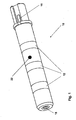
- fitting 10 has three annular contacts 12, which on one of in FIG. 1 not further recognizable spacers 14 formed carrier are arranged.
- the annular contacts 12 are each provided with leads 16 proximate a distal end of the fitting 10 (in FIG. 1 the right end of the fitting 10) ends.
- a key surface 18 At the proximal end of the fitting 10 is a key surface 18, which is part of a key segment 20 (see FIG. 2 ).
- the connecting piece 10 is encapsulated with insulating plastic, the insulating surfaces 22 between bare, electrically conductive outer surfaces of the annular contacts 12 forms.
- FIG. 2 the components of the connector 10 are shown individually in an exploded view.
- three annular contacts 12 are provided with connection lines 16 attached to them. Since the annular contacts 12, like FIG. 1 can be seen, are offset in the longitudinal direction of the connecting piece 10 to each other, the connecting lines 16 of the individual annular contacts 12 have different lengths and thus have at their respective distal end the same distance from the distal end of the connector 10th
- Each of the annular contact elements 12 is supported by a respective intermediate piece 14.
- three intermediate pieces 14 are provided, which are identical to each other.
- Each of the intermediate pieces 14 has a proximal longitudinal portion 24 and a distal longitudinal portion 26 and a transitional region 28 therebetween.
- a portion of the proximal longitudinal portion 24 of a respective intermediate piece 14 serves as a seat 30 for a respective annular contact 12.
- the respective distal longitudinal sections 26 of a respective intermediate piece 14 have a smaller diameter than the proximal longitudinal sections 24, which is dimensioned such that a respective distal longitudinal section 26 can be snugly inserted into a central opening in the proximal longitudinal section 24 of an identical intermediate section 14.
- several intermediate pieces 14 can be connected to each other in the longitudinal direction. In the transition region 26 between the two longitudinal sections of a respective intermediate piece 14, the outer diameter of the intermediate piece is reduced.
- recesses 34, 36 and 38 On the outside of the longitudinal sections 24 and 26 of the intermediate pieces 14 are provided in the longitudinal direction extending recesses 34, 36 and 38. These recesses 34, 36 and 38 serve to receive a respective connection line 16 of an annular contact 12.
- the recesses 34, 36 and 38 are arranged so that a connection line 16 of a respective contact 12 from the outside of a respective proximal longitudinal portion of the corresponding intermediate piece 14th in a recess (in this case in each case the recess 38) is guided to the outside of the distal longitudinal portion 26 of the respective intermediate piece 14.
- the remaining recesses 36 are arranged on a respective distal longitudinal section 26 of an intermediate piece 14 in extension of an opening 40 in the transitional area 28 of a respective intermediate piece 14.
- the apertures 40 allow a respective recess 38 to continue in a straight direction in correspondingly aligned recesses 36 of one or more intermediate pieces 14 arranged more distally.
- a termination piece 42 having a proximal end portion 44 and a distal end portion 46.
- the proximal end portion 44 is configured similar to the proximal longitudinal portions 24 of the intermediate pieces 14, but has no seat for a further annular electrode.
- the distal end portion 46 of the end piece 42 has approximately the same outer diameter as the proximal end portion 44 of the end piece 42 and also has longitudinal recesses 48. As FIG. 1 it can be seen, terminate the connecting lines 16 in a respective one of these wells 48 when the connector 10 is fully assembled. The ends of the connecting lines 16 are accessible in the recesses 48 from the outside.
- FIG. 3 shows a plugged spacer 10 before encapsulation with insulating plastic.
- FIG. 4 In order to connect the finished connector 10 with a remaining electrode line, more parts are required in FIG. 4 are shown. These are a silicone sleeve 50, a closing ring 52, a plug pin 54 and a marking tape 56.
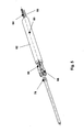
- the end piece 10 can be connected to a proximal end of an as far as preconfigured electrode line 60, as shown in FIG FIG. 5 is shown.
- FIG. 5 shows only the proximal end of such preconfigured electrode lead 60.
- the electrode line 60 has a flexurally soft shell 62, which has a central lumen for a central, helically coiled feed line 64 and further outwardly arranged lumens for electrical leads 66.
- the electrical supply lines 66 are equipped at their respective proximal end with a respective crimping sleeve 68, which serves to connect the electrical supply lines 66 to the connection lines 16 of the annular electrodes 12.
- a sleeve 70 which extends through a continuous central lumen of the fitting 10 enclosed by the endpiece 42 and the spacers 14 when the fitting 10 is secured to the electrode lead 60.
- a proximal end of the sleeve 70 is then connected to the male pin 54.
- the plug pin 54 then forms a central contact for the helically coiled line 64th
- the crimp sleeves 68 are attached by crimping at the ends of the leads 66.
- the sleeve 70 is connected by laser welding to the proximal end of the helically coiled line 64.
- the prepared, in FIG. 5 The illustrated proximal end of the electrode lead 60 is then inserted into the fitting 10 and fixed to the plug pin 54.
- the silicone sleeve 50 and the end ring 52 are then brought over the transition points as connecting elements.
- the marker band 56 covers a Abschmelzkante for the laser weld between the connector pin 54 and the sleeve 70 from.
Description
Die Erfindung betrifft eine Elektrodenleitung zum Anschluss an einen implantierbaren Herzstimulator wie beispielsweise einen Herzschrittmacher oder einen Cardioverter/Defibrillator. Insbesondere betrifft die Erfindung ein Anschlussstück für eine solche Elektrodenleitung.The invention relates to an electrode lead for connection to an implantable cardiac stimulator such as a pacemaker or a cardioverter / defibrillator. In particular, the invention relates to a connector for such an electrode line.
Implantierbare Herzstimulatoren der genannten Art sind in verschiedenen Ausführungen grundsätzlich bekannt. Derartige Herzstimulatoren weisen üblicherweise ein dichtes Gehäuse auf, welches eine Stromversorgung und weitere elektronische und elektrische Bauteile umfasst, um Stimulationsimpulse oder Defibrillationsschocks zu erzeugen und über eine Elektrodenleitung an eine oder mehrere Kammern eines Herzens abzugeben oder um elektronische Potentiale im Herzen zu erfassen und zu verarbeiten. Zu diesem Zweck sind solche implantierbaren Herzstimulatoren üblicherweise mit Elektrodenleitungen verbunden, die mit einem Anschlussstück am proximalen Ende der Elektrodenleitung in eine Buchse in einem sogenannten Header des jeweiligen Herzstimulators eingesteckt sind. Sowohl das Anschlussstück als auch die Buchse im Header des Herzstimulators weisen miteinander korrespondierende elektrische Kontakte auf, um eine elektrisch leitende Verbindung zwischen dem Herzstimulator und der Elektrodenleitung herzustellen.Implantable cardiac stimulators of the type mentioned are basically known in various designs. Such cardiac stimulators usually have a sealed housing which includes a power supply and other electronic and electrical components to generate stimulation pulses or defibrillation shocks and deliver via an electrode lead to one or more chambers of a heart or to detect and process electronic potentials in the heart. For this purpose, such implantable cardiac stimulators are usually connected to electrode leads, which are inserted with a connector at the proximal end of the electrode lead into a socket in a so-called header of the respective cardiac stimulator. Both the connector and the socket in the header of the cardiac stimulator have electrical contacts corresponding to each other to establish an electrically conductive connection between the cardiac stimulator and the electrode lead.
Dementsprechend weist das Anschlussstück am proximalen Ende der Elektrodenleitung elektrische Kontakte auf, die mit Anschlussleitungen verbunden sind, welche wenigstens den Teil einer elektrischen Verbindung zu Stimulations- und/oder Abfühlelektroden im Bereich des distalen Endes einer solchen Elektrodenleitung herstellen. Solche Elektrodenleitungen sind üblicherweise flexibel (also biegeweich) und in mannigfacher Ausführung bekannt.Accordingly, the connector at the proximal end of the electrode lead has electrical contacts connected to leads which provide at least the portion of an electrical connection to stimulation and / or sense electrodes in the region of the distal end of such an electrode lead. Such electrode lines are usually flexible (ie bend soft) and known in manifold design.
Die vorliegende Erfindung gilt dem Anschlussstück am proximalen Ende der Elektrodenleitung und dessen Verbindung zu übrigen Elektrodenleitungen.The present invention applies to the fitting at the proximal end of the electrode lead and its connection to other electrode leads.
Das hier betroffene Anschlussstück ist dabei von der Art, die mehrere, ringförmige Kontakte gleichen Außendurchmessers aufweist und der zukünftigen Norm IS-4 entspricht. Eine Variante eines derartigen Anschlussstücks ist beispielsweise in
Das Dokument
Aufgabe der Erfindung ist es, ein Anschlussstück und eine Elektrodenleitung mit einem solchen Anschlussstück zu schaffen, die unabhängig von der Art und Zahl der Kontakte der Elektrodenleitung sind, mit vertretbaren Aufwand herzustellen sind und eine hohe Zuverlässigkeit besitzen.The object of the invention is to provide a connection piece and an electrode line with such a connection piece, which are independent of the type and number of contacts of the electrode line, are to produce with reasonable effort and have a high reliability.
Erfindungsgemäß wird diese Aufgabe durch ein Anschlussstück sowie durch eine Elektrodenleitung mit einem Anschlussstück gelöst, das mehrere ringförmige, elektrisch leitende Kontakte gleichen Außendurchmesser mit in Längsrichtung dazwischen angeordneten Isolationsabschnitten desselben Außendurchmesser aufweist, von denen die elektrisch leitenden Kontakte mit jeweils einer elektrisch leitenden Anschlussleitung elektrisch leitend verbunden sind. Das erfindungsgemäße Anschlussstück ist von mehreren isolierenden Zwischenstücken und von von diesen gehaltenen elektrischen Kontakten mit daran befestigten Anschlussleitungen gebildet, in Längsrichtung des Anschlussstücks zusammengesteckt und nach dem Zusammenstecken mit isolierenden Kunststoff umspritzt. Dabei ragen die Anschlussleitungen entweder gar nicht oder höchstens um ein Maß über ein distales des Anschlussstücks hinaus, welches geringer ist, als die übrige Länge des AnschlussstücksAccording to the invention this object is achieved by a connector and by an electrode line with a connector having a plurality of annular, electrically conductive contacts same outer diameter with longitudinally disposed therebetween insulation portions of the same outer diameter, of which the electrically conductive contacts each electrically connected to an electrically conductive connection line are. The connecting piece according to the invention is formed by a plurality of insulating intermediate pieces and held by these electrical contacts with connecting leads attached thereto, plugged together in the longitudinal direction of the connecting piece and encapsulated after being plugged together with insulating plastic. In this case, the connection lines either do not protrude at all or at most extend beyond the distal end of the connection piece, which is smaller than the remaining length of the connection piece
Die Zwischenstücke sind vorzugsweise als Vorspritzlinge mittels Spritzguss hergestellt.The intermediate pieces are preferably produced as pre-molded parts by means of injection molding.
Im Übrigen ist das erfindungsgemäße Anschlussstück so ausgebildet, dass es als eigenständige Einheit mit einer übrigen Elektrodenleitung zu verbinden ist.Incidentally, the connector according to the invention is designed so that it is to be connected as a separate unit with a remaining electrode line.
Dies erlaubt es, dass vollständige Anschlussstück vorzufertigen und zu prüfen, bevor es mit der übrigen Elektrodenleitung verbunden wird. Damit kann ein fehlerhaftes Anschlussstück schon identifiziert werden, bevor es mit der übrigen Elektrodenleitung verbunden wird. Im Falle eines Fehlers am Anschlussstück produzierter Ausschuss betrifft somit nicht die gesamte Elektrodenleitung.This allows the complete connector to be prefabricated and tested before it is connected to the remainder of the electrode lead. Thus, a faulty connector can already be identified before it is connected to the rest of the electrode line. In the case of a fault produced on the connector committee thus does not affect the entire electrode line.
Für das Umspritzen erforderliche Angüsse und zwingend notwendige Trennebenen von Spritzgussformen sind so gelegt, dass eine äußere Oberfläche des isolierenden Kunststoffes im Bereich zwischen den einzelnen elektrischen Kontakten und proximal des am weitesten proximal angeordneten Kontaktes keine Werkzeugmarken aufweisen. Aus praktischen Erwägungen wie beispielsweise aus Anforderungen, die sich aus der Biokompatibilität ergeben, kann das Umspritzen auch aus mehreren Schritten mit differierenden Materialien geschehen, so dass sich eine heterogene Außenstruktur ergibt, die die Zwischenstücke zumindest teilweise umschließt.For overmolding required sprues and absolutely necessary parting lines of injection molds are placed so that an outer surface of the insulating plastic in the region between the individual electrical contacts and proximal of the most proximal contact arranged have no tool marks. For practical reasons, such as requirements resulting from biocompatibility, overmolding can also be done in several steps with different materials, resulting in a heterogeneous external structure that at least partially encloses the intermediate pieces.
Alternativ hierzu können die Zwischenstücke so ausgebildet und in Längsrichtung zusammengesteckt sein, dass sie zusammen mit den elektrischen Kontakten die Außenkontur des Anschlussstücks bilden und ein von den Zwischenstücken umschlossener Innenraum des Anschlussstücks mit isolierendem Kunststoff ausgespritzt ist.Alternatively, the intermediate pieces may be formed and plugged together in the longitudinal direction that they form together with the electrical contacts, the outer contour of the connector and an enclosed by the intermediate pieces interior of the connector with insulating plastic is injected.
In beiden Fällen dienen die Zwischenstücke sowohl der axialen als auch radialen Lagesicherung der elektrisch leitenden Kontakte.In both cases, the intermediate pieces serve both the axial and radial position assurance of the electrically conductive contacts.
Um eine rationelle Fertigung zu gewährleisten und die Zuverlässigkeit des Anschlussstücks zu erhöhen, ist es vorgesehen, dass wenigstens zwei der isolierenden Zwischenstücke einander identisch sind. Dies bringt den weiteren Vorteil mit sich, dass das Anschlussstück ohne weiteres mit einer, zwei oder drei ringförmigen Kontakten aufgebaut werden kann, ohne dass hierzu andere Bauteile nötig wären.In order to ensure a rational production and to increase the reliability of the connection piece, it is provided that at least two of the insulating intermediate pieces are identical to one another. This has the further advantage that the connecting piece can be readily constructed with one, two or three annular contacts, without the need for other components.
Vorzugsweise besitzen die identischen Zwischenstücke jeweils einen passgenauen Sitz für einen jeweiligen ringförmigen Kontakt. Dies bedeutet, dass das jeweilige Zwischenstück wenigstens in einem Längsabschnitt eine äußere Abmessung besitzt, die dem Innendurchmesser der ringförmigen Kontakte entspricht.Preferably, the identical intermediate pieces each have a snug fit for a respective annular contact. This means that the respective intermediate piece, at least in a longitudinal section, has an outer dimension which corresponds to the inner diameter of the annular contacts.
Im Zusammenhang mit der zuletzt genannten Ausführungsvariante ist es vorteilhaft, wenn die einander identischen Zwischenstücke in einem jeweiligen proximalen Längsabschnitt einen Längsanschlag besitzen, der ein Aufschieben eines jeweiligen ringförmigen Kontaktes in proximale Richtung begrenzt. Dabei hat der Längsabschnitt vorzugsweise einen Längsabstand zu einem proximalen Ende eines jeweiligen Zwischenstücks, der dem Längsabstand zwischen den ringförmigen Kontakten entspricht und damit die Isolationslänge zwischen den ringförmigen Kontakten definiert.In connection with the last-mentioned embodiment variant, it is advantageous if the identical intermediate pieces in a respective proximal longitudinal section have a longitudinal stop which limits a sliding of a respective annular contact in the proximal direction. In this case, the longitudinal section preferably has a longitudinal distance to a proximal end of a respective intermediate piece, the Longitudinal distance between the annular contacts corresponds and thus defines the insulation length between the annular contacts.
In einem distalen Längsabschnitt weisen die einander identischen Zwischenstücke einen geringeren Außendurchmesser auf als in ihrem proximalen Längsabschnitt. Dabei ist der Außendurchmesser des distalen Längsabschnitts so bemessen, dass ein jeweiliger distaler Längsabschnitt genau in eine zentrale Öffnung im proximalen Längsabschnitt eines identischen Zwischenstücks passt, so dass die Zwischenstücke auf diese Weise ineinander zu stecken sind. Durch Ineinanderstecken der aufeinander folgenden Zwischenstücke entsteht somit ein zusammenhängender Träger für die ringförmigen Kontakte der keines weiteren Trägerelementes bedarf und die ringförmigen Kontakte sowohl radial als auch axial fixiert. Somit erlauben es die Zwischenstücke auf einfache Art und Weise einen Träger für die Kontakte herzustellen, der hinsichtlich seiner Länge und der Anzahl der Kontakte flexibel ist.In a distal longitudinal section, the identical intermediate pieces have a smaller outer diameter than in their proximal longitudinal section. In this case, the outer diameter of the distal longitudinal section is dimensioned such that a respective distal longitudinal section fits exactly into a central opening in the proximal longitudinal section of an identical intermediate piece, so that the intermediate sections are to be inserted into one another in this way. By nesting the successive intermediate pieces thus creates a contiguous support for the annular contacts which requires no further support member and fixes the annular contacts both radially and axially. Thus, the spacers allow a simple way to produce a support for the contacts, which is flexible in terms of its length and the number of contacts.
Hierbei bildet jeweils ein Abschnitt des jeweiligen proximalen Längsabschnitts eines jeweiligen Zwischenstückes mit seinem relativ größeren Außendurchmesser den Sitz für einen jeweiligen ringförmigen Kontakt.In this case, in each case a section of the respective proximal longitudinal section of a respective intermediate piece with its relatively larger outer diameter forms the seat for a respective annular contact.
Vorzugsweise weisen die Zwischenstücke auf ihrer Außenseite wenigstens eine in Längsrichtung verlaufende Vertiefung auf, die der Aufnahme einer jeweiligen Anschlussleitung eines ringförmigen Kontaktes dient.Preferably, the intermediate pieces have on their outer side at least one recess extending in the longitudinal direction, which serves to receive a respective connecting line of an annular contact.
Neben den Zwischenstücken besitzt das Anschlussstück vorzugsweise ein distales Abschlussstück, welches einen proximalen Endabschnitt und einen distalen Endabschnitt besitzt. Beide Endabschnitte weisen vorzugsweise annähernd den gleichen Außendurchmesser auf. Der proximale Endabschnitt des distalen Abschlussstücks entspricht vorzugsweise einem jeweiligen proximalen Längsabschnitt der Zwischenstücke zwischen dem proximalen Ende des jeweiligen Zwischenstücks und dem Längsanschlag, d. h. die proximalen Endabschnitte aller Zwischenstücke und des distalen Abschlussstücks gleichen sich.In addition to the intermediate pieces, the connecting piece preferably has a distal end piece, which has a proximal end portion and a distal end portion. Both end portions preferably have approximately the same outer diameter. The proximal end portion of the distal end piece preferably corresponds to a respective proximal longitudinal portion of the intermediate pieces between the proximal end of the respective intermediate piece and the longitudinal stop, i. H. the proximal end portions of all intermediate pieces and the distal end piece are equal.
Auch das distale Abschlussstück weist in seinem proximalen Endabschnitt vorzugsweise wenigstens eine in Längsrichtung verlaufende Vertiefung zur Aufnahme einer Anschlussleitung eines ringförmigen Kontaktes auf. Dabei ist das distale Abschlussstück im Übrigen nicht zur Aufnahme eines weiteren ringförmigen Kontaktes ausgebildet, sondern vielmehr dazu, mit der übrigen Elektrodenleitung verbunden zu werden.Also, the distal end piece has in its proximal end portion preferably at least one longitudinally extending recess for receiving a connecting lead of an annular contact. Incidentally, the distal end piece is not formed for receiving a further annular contact, but rather to be connected to the other electrode line.
Die zusammengesteckten Zwischenstücke und das Abschlussstück sind vorzugsweise so zueinander ausgerichtet, dass die jeweiligen Vertiefungen auf der Außenseite der Zwischenstücke und des Abschlussstücks miteinander fluchten und es erlauben, dass eine jeweilige Anschlussleitung gestreckt und parallel zur Längsachse des Anschlussstücks in den Vertiefungen geführt ist. Dazu sind in einem Übergangsbereich der Zwischenstücke zwischen deren proximalem Längsabschnitt mit größerem Außendurchmesser und deren distalem Längsabschnitt mit geringerem Außendurchmesser Durchbrüche in Verlängerung einer jeweiligen Vertiefung vorgesehen, die es erlauben, dass eine jeweilige Anschlussleitung diesen Übergangsbereich eines jeweiligen Zwischenstücks durchdringt.The mated intermediate pieces and the end piece are preferably aligned with each other such that the respective recesses on the outside of the intermediate pieces and the end piece are aligned with each other and allow a respective lead to be stretched and guided parallel to the longitudinal axis of the fitting in the recesses. For this purpose, in a transition region of the intermediate pieces between their proximal longitudinal portion with a larger outer diameter and its distal longitudinal portion with a smaller outer diameter openings provided in extension of a respective recess, which allow a respective connecting line penetrates this transition region of a respective intermediate piece.
Vorzugsweise sind in jedem Zwischenstück und im distalen Abschlussstück zwei oder drei der Vertiefungen gleichmäßig über den Umfang verteilt vorgesehen. Dabei sind die Vertiefungen in den proximalen Längsabschnitten größeren Durchmessers der Zwischenstücke gegenüber den Vertiefungen in den distalen Längsabschnitten in Umfangsrichtung versetzt.Preferably, in each intermediate piece and in the distal end piece, two or three of the recesses are provided uniformly distributed over the circumference. The recesses in the proximal longitudinal sections of larger diameter of the intermediate pieces are offset relative to the recesses in the distal longitudinal sections in the circumferential direction.
Ein weiteres vorteilhaftes Merkmal eines bevorzugten Anschlussstücks ist ein zentrales Lumen, das sich zentral durch alle identischen Zwischenstücke sowie auch durch das Abschlussstück hindurch erstreckt und ein proximales Ende einer beispielsweise wendelförmigen elektrischen Leitung zentral aufnehmen kann.Another advantageous feature of a preferred fitting is a central lumen that extends centrally through all of the identical spacers as well as through the end cap and can centrally receive a proximal end of, for example, a helical electrical lead.
Darüber hinaus ist am proximalen Ende des Anschlussstücks ein Segment vorgesehen, welches in die Öffnung am proximalen Ende desjenigen der identischen Zwischenstücke passgenau eingesetzt ist, welches sich am proximalen Ende des Anschlussstücks befindet. Über das Segment können verschiedenartige Elektrodenleitungskonfigurationen mit feststehender bzw. drehbarer Elektrodenleitung an das fertig gestellte Anschlussstück angebracht werden, ohne dass das Anschlussstück verändert werden muss.In addition, a segment is provided at the proximal end of the connecting piece, which is inserted in the opening at the proximal end of that of the identical intermediate pieces, which is located at the proximal end of the connecting piece. Different electrode line configurations with a fixed or rotatable electrode cable can be attached to the finished connection piece via the segment without having to change the connection piece.
Das Anschlussstück der zuvor beschriebenen Art ist vorzugsweise Bestandteil einer Elektrodenleitung, die in ihrem distalen Ende wenigstens eine Elektrode und darüber hinaus wenigstens eine elektrische Zuleitung aufweist, mit ihrem distalen Ende mit dieser Elektrode elektrisch verbunden ist und mit ihrem proximalen Ende mit einer Anschlussleistung eines ringförmigen Kontaktes des Anschlussstücks über eine Crimp-, Schweiß- oder Lötverbindung elektrisch leitend verbunden ist.The connector of the type described above is preferably part of an electrode line having in its distal end at least one electrode and moreover at least one electrical lead, with its distal end electrically connected to this electrode and with its proximal end with a connected load an annular contact of the connection piece is electrically conductively connected via a crimping, welding or soldering connection.
Die Crimp-, Schweiß- oder Lötverbindung befindet sich dabei vorzugsweise jeweils in einer der in Längsrichtung verlaufenden Vertiefungen des distalen Abschlussstücks des Anschlussstücks. Da das distale Abschlussstück selbst aus isolierendem Kunststoff besteht und die einzelnen elektrischen Zuleitungen und Anschlussleitungen durch die verschiedenen Vertiefungen in dem Abschlussstück voneinander elektrisch isoliert sind, ist auch nach dem Verbinden der jeweiligen Anschlussleitung mit der zugehörigen elektrischen Zuleitung keine weitere Isolierung der Verbindungsstelle erforderlich.The crimping, welding or soldering connection is preferably located in each case in one of the longitudinally extending recesses of the distal end piece of the connection piece. Since the distal end piece itself is made of insulating plastic and the individual electrical leads and connecting lines are electrically insulated from each other by the various recesses in the end piece, no further isolation of the connection point is required even after connecting the respective connecting line with the associated electrical supply line.
Wie zuvor schon angedeutet, weist die Elektrodenleitung darüber hinaus vorzugsweise eine helixartig gewendelte (wendelförmige) Leitung auf, die sich zwischen dem distalen und dem proximalen Ende der Elektrodenleitung erstreckt und sich mit einem proximalen Leitungsendabschnitt in dem Lumen des Anschlussstücks erstreckt.In addition, as previously indicated, the electrode lead preferably includes a helically coiled (helical) lead extending between the distal and proximal ends of the electrode lead and extending with a proximal lead end portion in the lumen of the fitting.
Es versteht sich, dass verschiedene der vorgenannten und der in den abhängigen Ansprüchen genannten bevorzugten Merkmale des Anschlussstücks beziehungsweise der Elektrodenleitung miteinander kombiniert werden können.It is understood that various of the aforementioned and the preferred features of the connection piece or of the electrode line mentioned in the dependent claims can be combined with one another.
Eine dem Vorstehenden entsprechende Elektrodenleitung soll nun anhand eines Ausführungsbeispiels mit Bezug auf die Figuren näher erläutert werden. Von den Figuren zeigen:
- Fig. 1:
- ein als separate Einheit fertiggestelltes Anschlussstück in einer perspektivischen Außenansicht;
- Fig. 2:
- eine Explosionszeichnung des Anschlussstücks aus
Fig. 1 mit einer Darstellung der einzelnen Bestandteile; - Fig. 3:
- die zusammengesteckten Bestandteile des Anschlussstücks aus
Fig. 1 vor dem Umspritzen. - Fig. 4:
- das Anschlussstück aus
Fig. 1 nebst weiteren Bestandteilen zur Verbindung des Anschlussstücks einer übrigen Elektrodenleitung; und - Fig. 5:
- eine übrige Elektrodenleitung, die zur Verbindung mit dem Anschlussstück aus
Figuren 1 bis 4 vorkonfiguriert ist.
- Fig. 1:
- a completed as a separate unit fitting in a perspective exterior view;
- Fig. 2:
- an exploded view of the connector
Fig. 1 with a representation of the individual components; - 3:
- the assembled components of the connector off
Fig. 1 before overmolding. - 4:
- the connector off
Fig. 1 together with further components for connecting the connection piece of a remaining electrode line; and - Fig. 5:
- a remaining electrode line, which for connection to the connector off
FIGS. 1 to 4 is preconfigured.
Das in
In
Jedes der ringförmigen Kontaktelemente 12 wird von einem jeweiligen Zwischenstück 14 getragen. Insgesamt sind drei Zwischenstücke 14 vorgesehen, die einander identisch sind. Jedes der Zwischenstücke 14 besitzt einen proximalen Längsabschnitt 24 und einen distalen Längsabschnitt 26 und einen dazwischen angeordneten Übergangsbereich 28. Ein Teil des proximalen Längsabschnitts 24 eines jeweiligen Zwischenstücks 14 dient als Sitz 30 für einen jeweiligen ringförmigen Kontakt 12. Ein Längsanschlag 22, der einen gewissen Abstand zu einem distalen Ende eines jeweiligen Zwischenstücks 12 hat, definiert den Sitz 30 für die ringförmigen Elektroden 12 in Längsrichtung des jeweiligen proximalen Längsabschnitts 24 eines jeweiligen Zwischenstücks 12.Each of the
Die jeweiligen distalen Längsabschnitte 26 eines jeweiligen Zwischenstücks 14 besitzen einen geringeren Durchmesser als die proximalen Längsabschnitte 24, der so bemessen ist, dass ein jeweiliger distaler Längsabschnitt 26 in eine zentrale Öffnung im proximalen Längsabschnitt 24 eines identischen Zwischenstücks 14 passgenau einzustecken ist. Auf diese Weise können mehrere Zwischenstücke 14 in Längsrichtung miteinander verbunden werden. Im Übergangsbereich 26 zwischen den beiden Längsabschnitten eines jeweiligen Zwischenstücks 14 verringert sich der Außendurchmesser des Zwischenstücks.The respective distal
Auf der Außenseite der Längsabschnitte 24 und 26 der Zwischenstücke 14 sind in Längsrichtung verlaufende Vertiefungen 34, 36 und 38 vorgesehen. Diese Vertiefungen 34, 36 und 38 dienen der Aufnahme einer jeweiligen Anschlussleitung 16 eines ringförmigen Kontaktes 12. Dabei sind die Vertiefungen 34, 36 und 38 so angeordnet, dass eine Anschlussleitung 16 eines jeweiligen Kontaktes 12 von der Außenseite eines jeweiligen proximalen Längsabschnitts des entsprechenden Zwischenstücks 14 in einer Vertiefung (in diesem Falle jeweils die Vertiefung 38) zur Außenseite des distalen Längsabschnitts 26 des jeweiligen Zwischenstücks 14 geführt ist. Um die Anschlussleitungen 16 jeweils bis in die Nähe des distalen Endes des Anschlussstücks 10 führen zu können, sind die übrigen Vertiefungen 36 auf einem jeweiligen distalen Längsabschnitt 26 eines Zwischenstücks 14 in Verlängerung eines Durchbruchs 40 im Übergangsbereich 28 eines jeweiligen Zwischenstücks 14 angeordnet. Die Durchbrüche 40 erlauben es, dass eine jeweilige Vertiefung 38 sich in gerader Richtung in entsprechend fluchtenden Vertiefungen 36 eines oder mehrerer weiter distal angeordneter Zwischenstücke 14 fortsetzt.On the outside of the
Am distalen Ende des Anschlussstücks 10 ist ein Abschlussstück 42 angeordnet, das einen proximalen Endabschnitt 44 und einen distalen Endabschnitt 46 besitzt. Der proximale Endabschnitt 44 ist ähnlich gestaltet wie die proximalen Längsabschnitte 24 der Zwischenstücke 14, weist jedoch keinen Sitz für eine weitere ringförmige Elektrode auf. Der distale Endabschnitt 46 des Abschlussstücks 42 besitzt in etwa den gleichen Außendurchmesser wie der proximale Endabschnitt 44 des Abschlussstücks 42 und weist ebenfalls in Längsrichtung verlaufende Vertiefungen 48 auf. Wie
Wie bereits erwähnt, können die Zwischenstücke 14 sowie das Abschlussstück 42 in Längsrichtung ineinander gesteckt werden und bilden auf diese Weise einen Kontaktträger für die elektrischen Kontakte 12.
Um das fertiggestellte Anschlussstück 10 mit einer übrigen Elektrodenleitung verbinden zu können, sind weitere Teile erforderlich, die in
Mit Hilfe der letztgenannten Bestandteile kann das Abschlussstück 10 mit einem proximalen Ende einer insoweit vorkonfigurierten Elektrodenleitung 60 verbunden werden, wie es in
Um das fertiggestellte Anschlussstück 10 mit der Elektrodenleitung 60 zu verbinden, sind somit die folgenden Montageschritte erforderlich. Zunächst werden an den Enden der Zuleitungen 66 die Crimphülsen 68 durch Crimpen befestigt. Anschließend wird die Hülse 70 durch Laserschweißen mit dem proximalen Ende der helixartig gewendelten Leitung 64 verbunden. Das vorbereitete, in
Diese Beschreibung eines bevorzugten Ausführungsbeispiels macht deutlich, dass das Abschlussstück 10 bereits vor seiner Verbindung mit einer Elektrodenleitung 60 weitestgehend fertiggestellt und geprüft werden kann, so dass sichergestellt ist, dass das Abschlussstück 10 fehlerfrei ist, wenn es mit der Elektrodenleitung 60 verbunden wird. Dies senkt die Ausschlussquote und erhöht die Qualität der fertigen Elektrodenleitung.This description of a preferred embodiment makes it clear that the
Claims (22)
- A terminal piece for an electrode lead for connecting to an implantable cardiac stimulator and/or implantable defibrillator, the terminal piece having multiple annular, electrically conductive contacts (12) of identical outside diameters having insulation sections of the same outside diameters disposed between them in the longitudinal direction, each of the electrically conductive contacts being connected in an electrically conductive manner to an electrically conductive connecting line, the terminal piece being formed by multiple insulating intermediate pieces (14), of which at least some are identical to each other, and by electrical contacts held thereby having connecting lines fastened thereto, which are plugged together and are connected by way of a thermoplastic injection molding compound after being plugged together, the terminal piece otherwise being designed so that it is to be connected to a remaining electrode lead as an independent unit, characterized in that the intermediate pieces that are identical to each other have a smaller outside diameter in a respective distal longitudinal section than in the proximal longitudinal sections thereof, the outside diameter in the distal longitudinal section being dimensioned so that a respective distal longitudinal section fits exactly into a central opening in the proximal longitudinal section of an identical intermediate piece, so that the intermediate pieces are in this way plugged into each other and are thus connected to each other.
- The terminal piece according to claim 1, characterized in that the insulating intermediate pieces are disposed in the interior of the terminal piece, and the outside contour of the terminal piece is formed by the injection molding compound together with the electrically conductive contacts by encapsulating the intermediate pieces with the injection molding compound after the intermediate pieces and the electrical contacts have been joined.
- The terminal piece according to claim 1, characterized in that the insulating intermediate pieces together with the electrically conductive contacts form the outside contour of the terminal piece and enclose an inner space into which the injection molding compound is introduced by injection molding after the intermediate pieces and the electrical contacts have been joined.
- A terminal piece according to any one of claims 1 to 3, characterized in that the connecting lines end proximally from the distal end of the terminal piece.
- A terminal piece according to any one of claims 1 to 4, characterized in that the injection molding compound is made of a single material.
- The terminal piece according to claim 5, characterized in that the injection molding compound comprises PEEK.
- A terminal piece according to any one of claims 1 to 4, characterized in that the injection molding compound comprises at least two materials.
- The terminal piece according to claim 7, characterized in that the injection molding compound comprises PEEK and polyurethane.
- A terminal piece according to any one of claims 1 to 8, characterized in that each of the intermediate pieces that are identical to each other has a precisely fitting seat for a respective annular contact.
- The terminal piece according to claim 9, characterized in that the intermediate pieces that are identical to each other have a longitudinal stop in a respective proximal longitudinal section, the stop delimiting pushing of an annular contact in the proximal direction.
- The terminal piece according to claim 10, characterized in that the longitudinal stop has a longitudinal distance from the proximal end of each of the identical intermediate pieces, this longitudinal distance defining the longitudinal distance and thus also an insulation length between the annular contacts.
- A terminal piece according to any one of claims 1 to 11, characterized in that the relatively larger outside diameter of the proximal longitudinal section of a respective intermediate piece forms the seat for a respective annular contact.
- A terminal piece according to any one of claims 1 to 12, characterized in that the outsides of the intermediate pieces that are identical to each other each have at least one depression extending in the longitudinal direction for receiving a connecting line of an annular contact.
- The terminal piece according to claim 13, characterized in that the intermediate pieces that are identical to each other each have a transition region between the respective proximal longitudinal section and the respective distal longitudinal section, the outside diameter decreasing in this transition region and this region in extension of a respective depression having an aperture, which leads from the outside of the distal longitudinal section into the inside of the proximal longitudinal section.
- A terminal piece according to any one of claims 1 to 14, characterized in that the terminal piece comprises a distal end piece, which has a proximal end section and a distal end section, which both have approximately the same outside diameters and of which the proximal end section of the distal end piece corresponds to a respective proximal longitudinal section of the intermediate pieces that are identical to each other between the proximal end of the respective intermediate piece and the longitudinal stop of the same intermediate piece.
- The terminal piece according to claim 15, characterized in that the outside of the proximal end section of the distal end piece has at least one depression extending in the longitudinal direction for receiving a connecting line of an annular contact.
- A terminal piece according to claims 13 and 16, characterized in that, over the circumference of the longitudinal sections or of the distal end section, each of the intermediate pieces and the distal end piece have three depressions distributed evenly over the respective circumference for receiving a total of three connecting lines of likewise three annular contacts, which are oriented with respect to each other in such a way that they are each aligned in the longitudinal direction.
- A terminal piece according to any one of claims 1 to 17, characterized in that the terminal piece has a central, free lumen extending over the entire length of the terminal piece.
- A terminal piece according to any one of claims 1 to 18, characterized in that the terminal piece has a positively fitting segment, which is inserted with precise fit into the opening at the proximal end of that piece of the identical intermediate pieces which is located at the proximal end of the terminal piece.
- An electrode lead, comprising at the distal end thereof at least one electrode and at least one electrical supply line, which is electrically connected to this electrode, characterized in that the electrical supply line is connected in an electrically conductive manner to a connecting line of an annular contact by way of a crimp, weld, or solder joint, the electrode lead comprising a terminal piece according to any one of claims 1 to 19.
- The electrode lead according to claim 20, characterized in that the crimp, weld, or solder joint is located in each case in one of the depressions extending in the longitudinal direction on the outside of the distal end section of the distal end piece.
- An electrode lead according to claim 18 and claim 20, characterized in that the electrode lead comprises a helical line which extends between the distal end and the proximal end of the electrode lead and the proximal lead end section of which extends into the lumen of the terminal piece.
Applications Claiming Priority (1)
| Application Number | Priority Date | Filing Date | Title |
|---|---|---|---|
| DE102007006089A DE102007006089A1 (en) | 2007-02-07 | 2007-02-07 | Electrode lead and connector for an implantable cardiac stimulator |
Publications (3)
| Publication Number | Publication Date |
|---|---|
| EP1955729A2 EP1955729A2 (en) | 2008-08-13 |
| EP1955729A3 EP1955729A3 (en) | 2012-10-03 |
| EP1955729B1 true EP1955729B1 (en) | 2014-01-15 |
Family
ID=39033808
Family Applications (1)
| Application Number | Title | Priority Date | Filing Date |
|---|---|---|---|
| EP07023315.0A Not-in-force EP1955729B1 (en) | 2007-02-07 | 2007-12-01 | Electrode wire and connector piece for an implantable heart stimulator |
Country Status (3)
| Country | Link |
|---|---|
| US (1) | US7822476B2 (en) |
| EP (1) | EP1955729B1 (en) |
| DE (1) | DE102007006089A1 (en) |
Families Citing this family (5)
| Publication number | Priority date | Publication date | Assignee | Title |
|---|---|---|---|---|
| DE102008008927A1 (en) | 2008-02-13 | 2009-08-20 | Biotronik Crm Patent Ag | Electrode lead and fitting for electromedical implants |
| US9421362B2 (en) | 2011-10-28 | 2016-08-23 | Medtronic, Inc. | Modular lead end |
| US9101776B2 (en) | 2013-12-18 | 2015-08-11 | Medtronic, Inc. | Implantable medical electrical lead connector assemblies and methods of manufacture |
| US9072909B1 (en) | 2013-12-18 | 2015-07-07 | Medtronic, Inc. | Implantable medical electrical lead connectors, assemblies thereof, and methods of manufacture |
| EP3673951B1 (en) | 2018-12-28 | 2022-05-04 | Heraeus Medical Components, LLC | Overmolded segmented electrode |
Family Cites Families (5)
| Publication number | Priority date | Publication date | Assignee | Title |
|---|---|---|---|---|
| US5267564A (en) * | 1991-06-14 | 1993-12-07 | Siemens Pacesetter, Inc. | Pacemaker lead for sensing a physiologic parameter of the body |
| JP3569658B2 (en) * | 2000-02-18 | 2004-09-22 | 英朗 茂治 | Assembly method of coaxial multipolar plug and coaxial multipolar plug |
| US7108549B2 (en) | 2004-03-30 | 2006-09-19 | Medtronic, Inc. | Medical electrical connector |
| US20070027517A1 (en) * | 2005-07-29 | 2007-02-01 | Bischoff Thomas C | Medical electrical lead connector ring |
| US7326083B2 (en) * | 2005-12-29 | 2008-02-05 | Medtronic, Inc. | Modular assembly of medical electrical leads |
-
2007
- 2007-02-07 DE DE102007006089A patent/DE102007006089A1/en not_active Withdrawn
- 2007-12-01 EP EP07023315.0A patent/EP1955729B1/en not_active Not-in-force
-
2008
- 2008-01-30 US US12/022,706 patent/US7822476B2/en not_active Expired - Fee Related
Also Published As
| Publication number | Publication date |
|---|---|
| DE102007006089A1 (en) | 2008-08-14 |
| US20080188919A1 (en) | 2008-08-07 |
| US7822476B2 (en) | 2010-10-26 |
| EP1955729A3 (en) | 2012-10-03 |
| EP1955729A2 (en) | 2008-08-13 |
Similar Documents
| Publication | Publication Date | Title |
|---|---|---|
| EP2111895B1 (en) | Connection housing for an electromedical implant | |
| EP3725366B1 (en) | Electrical contact component | |
| EP1062970B1 (en) | Electrode assembly | |
| DE69824425T2 (en) | CONNECTION SYSTEM FOR PACING PIPES | |
| DE2902440C2 (en) | Socket for electrical plug-in contact connection and method for producing such a socket | |
| EP2823856B1 (en) | Spring contact component, plug contact socket, and contact socket component | |
| DE69931269T2 (en) | DEVICE IN CONNECTION WITH PACEMAKERS | |
| DE3140075C2 (en) | ||
| DE102007012124A1 (en) | Compression connector for coaxial cable, has connector body defining bore, and compression unit including two ends and external surface that includes channel, where channel includes inclined, perpendicular or radiussed side walls | |
| DE102008008927A1 (en) | Electrode lead and fitting for electromedical implants | |
| EP1955729B1 (en) | Electrode wire and connector piece for an implantable heart stimulator | |
| WO2011117773A1 (en) | Endotracheal tube | |
| DE3334550A1 (en) | ELECTRICAL CONNECTOR | |
| DE2228846A1 (en) | Cable termination | |
| DE69934138T2 (en) | CASE WITH CYLINDER CONNECTING PIECE FOR A PACEMAKER | |
| DE3914677A1 (en) | ELECTRICAL CONNECTING DEVICE FOR PRODUCING MECHANICAL AND ELECTRICAL CONNECTIONS BETWEEN AN IMPLANTABLE MEDICAL DEVICE AND A DELIVERY SYSTEM | |
| DE102006037122B3 (en) | Medical electrode with at least two poles and a plug and their use | |
| EP2604312B1 (en) | Conductive coil arrangement and electrode catheter arrangement, in particular for cardiac therapy | |
| DE102018124307A1 (en) | Plug with an overmolded, non-rotatable plug connection and four connections, in particular IS4 / DF4 plug | |
| EP1936758A2 (en) | Connector with contacts for transmitting signal data | |
| EP1974768A1 (en) | Sealing element and contact header for a medical implant | |
| EP3630266B1 (en) | Electromedical adapter, electromedical electrode and electromedical pulse generator | |
| EP2110156B1 (en) | Field decoupling element for use with an implantable lead and implantable medical device | |
| EP2422839B1 (en) | Electrode catheter, in particular for cardiac therapy | |
| DE202007019606U1 (en) | Sealing element and contact socket for medical implant |
Legal Events
| Date | Code | Title | Description |
|---|---|---|---|
| PUAI | Public reference made under article 153(3) epc to a published international application that has entered the european phase |
Free format text: ORIGINAL CODE: 0009012 |
|
| AK | Designated contracting states |
Kind code of ref document: A2 Designated state(s): AT BE BG CH CY CZ DE DK EE ES FI FR GB GR HU IE IS IT LI LT LU LV MC MT NL PL PT RO SE SI SK TR |
|
| AX | Request for extension of the european patent |
Extension state: AL BA HR MK RS |
|
| PUAL | Search report despatched |
Free format text: ORIGINAL CODE: 0009013 |
|
| AK | Designated contracting states |
Kind code of ref document: A3 Designated state(s): AT BE BG CH CY CZ DE DK EE ES FI FR GB GR HU IE IS IT LI LT LU LV MC MT NL PL PT RO SE SI SK TR |
|
| AX | Request for extension of the european patent |
Extension state: AL BA HR MK RS |
|
| RIC1 | Information provided on ipc code assigned before grant |
Ipc: H01R 13/52 20060101ALI20120829BHEP Ipc: A61N 1/05 20060101AFI20120829BHEP Ipc: H01R 107/00 20060101ALI20120829BHEP |
|
| 17P | Request for examination filed |
Effective date: 20130321 |
|
| 17Q | First examination report despatched |
Effective date: 20130425 |
|
| AKX | Designation fees paid |
Designated state(s): CH DE IE LI |
|
| GRAP | Despatch of communication of intention to grant a patent |
Free format text: ORIGINAL CODE: EPIDOSNIGR1 |
|
| INTG | Intention to grant announced |
Effective date: 20130924 |
|
| GRAS | Grant fee paid |
Free format text: ORIGINAL CODE: EPIDOSNIGR3 |
|
| GRAA | (expected) grant |
Free format text: ORIGINAL CODE: 0009210 |
|
| AK | Designated contracting states |
Kind code of ref document: B1 Designated state(s): CH DE IE LI |
|
| REG | Reference to a national code |
Ref country code: CH Ref legal event code: EP |
|
| REG | Reference to a national code |
Ref country code: IE Ref legal event code: FG4D Free format text: LANGUAGE OF EP DOCUMENT: GERMAN |
|
| REG | Reference to a national code |
Ref country code: DE Ref legal event code: R096 Ref document number: 502007012700 Country of ref document: DE Effective date: 20140227 |
|
| REG | Reference to a national code |
Ref country code: DE Ref legal event code: R097 Ref document number: 502007012700 Country of ref document: DE |
|
| PLBE | No opposition filed within time limit |
Free format text: ORIGINAL CODE: 0009261 |
|
| STAA | Information on the status of an ep patent application or granted ep patent |
Free format text: STATUS: NO OPPOSITION FILED WITHIN TIME LIMIT |
|
| 26N | No opposition filed |
Effective date: 20141016 |
|
| REG | Reference to a national code |
Ref country code: DE Ref legal event code: R097 Ref document number: 502007012700 Country of ref document: DE Effective date: 20141016 |
|
| REG | Reference to a national code |
Ref country code: DE Ref legal event code: R082 Ref document number: 502007012700 Country of ref document: DE Representative=s name: RANDOLL, SOEREN, DIPL.-CHEM. UNIV. DR. RER. NA, DE |
|
| PGFP | Annual fee paid to national office [announced via postgrant information from national office to epo] |
Ref country code: IE Payment date: 20161223 Year of fee payment: 10 Ref country code: DE Payment date: 20161212 Year of fee payment: 10 Ref country code: CH Payment date: 20161222 Year of fee payment: 10 |
|
| REG | Reference to a national code |
Ref country code: DE Ref legal event code: R119 Ref document number: 502007012700 Country of ref document: DE |
|
| REG | Reference to a national code |
Ref country code: CH Ref legal event code: PL |
|
| REG | Reference to a national code |
Ref country code: IE Ref legal event code: MM4A |
|
| PG25 | Lapsed in a contracting state [announced via postgrant information from national office to epo] |
Ref country code: IE Free format text: LAPSE BECAUSE OF NON-PAYMENT OF DUE FEES Effective date: 20171201 Ref country code: DE Free format text: LAPSE BECAUSE OF NON-PAYMENT OF DUE FEES Effective date: 20180703 |
|
| PG25 | Lapsed in a contracting state [announced via postgrant information from national office to epo] |
Ref country code: CH Free format text: LAPSE BECAUSE OF NON-PAYMENT OF DUE FEES Effective date: 20171231 Ref country code: LI Free format text: LAPSE BECAUSE OF NON-PAYMENT OF DUE FEES Effective date: 20171231 |