EP1953802A2 - Semiconductor process chamber - Google Patents
Semiconductor process chamber Download PDFInfo
- Publication number
- EP1953802A2 EP1953802A2 EP08250379A EP08250379A EP1953802A2 EP 1953802 A2 EP1953802 A2 EP 1953802A2 EP 08250379 A EP08250379 A EP 08250379A EP 08250379 A EP08250379 A EP 08250379A EP 1953802 A2 EP1953802 A2 EP 1953802A2
- Authority
- EP
- European Patent Office
- Prior art keywords
- lid
- container
- seal
- processing space
- metallic element
- Prior art date
- Legal status (The legal status is an assumption and is not a legal conclusion. Google has not performed a legal analysis and makes no representation as to the accuracy of the status listed.)
- Withdrawn
Links
Images



Classifications
-
- H—ELECTRICITY
- H10—SEMICONDUCTOR DEVICES; ELECTRIC SOLID-STATE DEVICES NOT OTHERWISE PROVIDED FOR
- H10P—GENERIC PROCESSES OR APPARATUS FOR THE MANUFACTURE OR TREATMENT OF DEVICES COVERED BY CLASS H10
- H10P72/00—Handling or holding of wafers, substrates or devices during manufacture or treatment thereof
- H10P72/04—Apparatus for manufacture or treatment
- H10P72/0441—Apparatus for sealing, encapsulating, glassing, decapsulating or the like
-
- Y—GENERAL TAGGING OF NEW TECHNOLOGICAL DEVELOPMENTS; GENERAL TAGGING OF CROSS-SECTIONAL TECHNOLOGIES SPANNING OVER SEVERAL SECTIONS OF THE IPC; TECHNICAL SUBJECTS COVERED BY FORMER USPC CROSS-REFERENCE ART COLLECTIONS [XRACs] AND DIGESTS
- Y10—TECHNICAL SUBJECTS COVERED BY FORMER USPC
- Y10S—TECHNICAL SUBJECTS COVERED BY FORMER USPC CROSS-REFERENCE ART COLLECTIONS [XRACs] AND DIGESTS
- Y10S277/00—Seal for a joint or juncture
- Y10S277/913—Seal for fluid pressure below atmospheric, e.g. vacuum
-
- Y—GENERAL TAGGING OF NEW TECHNOLOGICAL DEVELOPMENTS; GENERAL TAGGING OF CROSS-SECTIONAL TECHNOLOGIES SPANNING OVER SEVERAL SECTIONS OF THE IPC; TECHNICAL SUBJECTS COVERED BY FORMER USPC CROSS-REFERENCE ART COLLECTIONS [XRACs] AND DIGESTS
- Y10—TECHNICAL SUBJECTS COVERED BY FORMER USPC
- Y10S—TECHNICAL SUBJECTS COVERED BY FORMER USPC CROSS-REFERENCE ART COLLECTIONS [XRACs] AND DIGESTS
- Y10S277/00—Seal for a joint or juncture
- Y10S277/935—Seal made of a particular material
- Y10S277/939—Containing metal
-
- Y—GENERAL TAGGING OF NEW TECHNOLOGICAL DEVELOPMENTS; GENERAL TAGGING OF CROSS-SECTIONAL TECHNOLOGIES SPANNING OVER SEVERAL SECTIONS OF THE IPC; TECHNICAL SUBJECTS COVERED BY FORMER USPC CROSS-REFERENCE ART COLLECTIONS [XRACs] AND DIGESTS
- Y10—TECHNICAL SUBJECTS COVERED BY FORMER USPC
- Y10S—TECHNICAL SUBJECTS COVERED BY FORMER USPC CROSS-REFERENCE ART COLLECTIONS [XRACs] AND DIGESTS
- Y10S277/00—Seal for a joint or juncture
- Y10S277/935—Seal made of a particular material
- Y10S277/944—Elastomer or plastic
-
- Y—GENERAL TAGGING OF NEW TECHNOLOGICAL DEVELOPMENTS; GENERAL TAGGING OF CROSS-SECTIONAL TECHNOLOGIES SPANNING OVER SEVERAL SECTIONS OF THE IPC; TECHNICAL SUBJECTS COVERED BY FORMER USPC CROSS-REFERENCE ART COLLECTIONS [XRACs] AND DIGESTS
- Y10—TECHNICAL SUBJECTS COVERED BY FORMER USPC
- Y10S—TECHNICAL SUBJECTS COVERED BY FORMER USPC CROSS-REFERENCE ART COLLECTIONS [XRACs] AND DIGESTS
- Y10S414/00—Material or article handling
- Y10S414/135—Associated with semiconductor wafer handling
- Y10S414/139—Associated with semiconductor wafer handling including wafer charging or discharging means for vacuum chamber
-
- Y—GENERAL TAGGING OF NEW TECHNOLOGICAL DEVELOPMENTS; GENERAL TAGGING OF CROSS-SECTIONAL TECHNOLOGIES SPANNING OVER SEVERAL SECTIONS OF THE IPC; TECHNICAL SUBJECTS COVERED BY FORMER USPC CROSS-REFERENCE ART COLLECTIONS [XRACs] AND DIGESTS
- Y10—TECHNICAL SUBJECTS COVERED BY FORMER USPC
- Y10T—TECHNICAL SUBJECTS COVERED BY FORMER US CLASSIFICATION
- Y10T29/00—Metal working
- Y10T29/49—Method of mechanical manufacture
- Y10T29/49718—Repairing
- Y10T29/49719—Seal or element thereof
Definitions
- a semiconductor process chamber commonly comprises a container, a lid, and a seal that seals the interface therebetween.
- the lid is usually convertible between a condition whereat it seals the access opening into the processing space, and a condition whereat the access opening is uncovered for loading/unloading of the processing space.
- the container's interface surface and/or the lid's interface surface can include a circumferential groove in which the seal is situated.
- ultra-high-vacuum UHV - pressures lower than about 10 -7 pascal and/or 10 -9 torr
- ultra-high-purity UHP - total maximum contaminant level of 10 ppm
- Slow production rates e.g., caused by long pump-down times
- significant equipment downtime e.g., for seal replacement or interface cleaning
- substandard yields e.g., due to particle generation
- a seal comprises an elastomeric element and a metallic element that can seal the container-lid interface of a process chamber.
- the seal can be constructed to achieve ultra high vacuum levels without compromising on cleanliness, and still allow a clamped (rather than bolted) container-lid interface.
- the seal can efficiently be used in UHV and/or UHP processing chambers with unbolted and/or dynamic interfaces.
- the elastomeric element and the metallic element can be arranged and adapted to seal the chamber's interface sequentially during its conversion to a sealed condition.
- the elastomeric element creates a seal during early evacuation stages, with the help of a clamping device. This maintains the chamber's vacuum, so that pressure differential can continue to rise, and provide the sealing load necessary for the metallic element to create a seal.
- the composite seal capitalizes on the low-seating-load ability of elastomeric element, while still providing a metallic seal during high pressure differential periods.
- the elastomeric element and the metallic element can be arranged and adapted to seal the chamber's interface in series when processing chamber is in its sealed condition.
- the metallic element can be positioned upstream of the elastomeric element relative to the processing chamber. (In cylindrical processing chambers, for example, the metallic element can be positioned radially inward of the elastomeric element.) In this manner, the metallic element shields the elastomeric element from gas permeation, thermal exposure, and reactive plasmas, and/or ion-impingement.
- the metallic element can also shield the processing chamber from particles generated by the elastomeric element.
- a process chamber 10 comprises a container 12, a lid 14, and an interface 16 therebetween.
- the container 12 defines a processing space 20 (and an access opening 22 thereinto).
- the lid 14 is convertible between a sealed condition ( Figure 1A ), whereat it seals the access opening 22 into the processing space 20, and a loading/unloading condition ( Figure 1 B) , whereat the access opening 22 is uncovered.
- the process chamber 10 can be an ultra-high-vacuum (UHV) and/or ultra-high-purity (UHP) chamber which is part of a semiconductor manufacturing process.
- UHV ultra-high-vacuum
- UHP ultra-high-purity
- the substrate 24 e.g., a wafer
- the interface 16 is sealed, the substrate 24 can be processed within the container 12.
- the processing can comprise photo-masking, deposition, oxidation, nitridation, ion implantation, diffusion, and/or etching.
- the vacuum can be released within the processing space 20, and the lid can be converted from its sealed condition to its load-unload condition.
- the substrate 24 can be withdrawn from the processing space 20 (through the access opening 22) and the steps repeated for the next substrate (e.g., the next wafer in the processing line).
- the container 12 includes an interface surface 30 surrounding the access opening 22 and the lid 14 includes an interface surface 32 seated against the container's interface surface 30 when in its sealed condition. These surfaces 30/32 together define the interface 16 between the container 12 and the lid 14.
- a clamp 34 (or other suitable means) can be provided to brace, lock, or otherwise hold the lid 14 against the container 12.
- the container's interface surface 30 and/or the lid's interface surface 32 includes at least one groove 36.
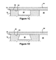
- the grooves 36 have a rectangular cross-sectional shapes. But, the groove 36 can have such a rectangular cross-section shape ( Figure 1 C) , a trapezoidal cross-section shape ( Figure 1 D) , or any other suitable cross-section shape.
- the groove 36 is continuous around the rim (e.g, perimeter, circumference) surrounding the processing chamber 20 and/or the access opening 22.
- a seal 40 is situated in the groove 36.
- the seal 40 has a generally ring-like shape, so as to be seated in the continuous groove 36.
- the seal 40 can generally comprises an elastomeric element 40 and a metallic element 50.
- the elastomeric element 40 can be made from polymeric materials including nylon, polytetrafluoroethylene, fluorinated ethylene-propylene, chlorotrifluoroethylene, perfluoroalkoxy polymer, polyvinyls, polyethylene, polypropylene, polystyrene, polysulfone and the like.
- the metallic element can be made from aluminum, steel, stainless steel, copper, brass, titanium, nickel, and alloys thereof.
- the elastomeric element 50 and the metallic element 60 can be arranged and adapted to seal the chamber's interface 16 sequentially during conversion to the sealed condition.
- the seal 40 can be designed so that the uncompressed height h 1 of the elastomeric element 40 is greater than the uncompressed height h 2 of the metallic element 50. (See A figures in 2 nd - 7 th drawing sets.) This height difference can result in the elastomeric element 50 being contacted and compressed prior to contact-compression of the metallic element 60.
- the elastomeric element When converting the lid 14 to the sealed condition, the elastomeric element is first contacted by the lid 14 (See B figures in 2 nd - 7 th drawing sets). Thereafter, possibly with the help of the clamp 34, the elastomeric element 50 is compressed. (See C figures in 2 nd - 7 th drawing sets.)
- the clamp 34 need only be sufficient to compress the elastomeric element 50 (not the metallic element 60), whereby an easily removable, and/or manually operable, clamping arrangement can be used.
- the elastomeric element 50 creates a seal during early evacuation stages, thereby allowing the vacuum to continue to build in the processing chamber 20. As the pressure differential rises, it creates a sealing load sufficient to compress the metallic element 60. (See D figures in 2 nd - 7 th drawing sets.)
- the elastomeric element 60 and the metallic element 60 can be arranged and adapted to seal the chamber's interface 16 in series when processing chamber 20 is in a sealed condition.
- the metallic element 50 can be situated to encounter processing activity upstream of the elastomeric element 40. In the illustrated embodiment, this upstream-orientation results in the metallic element 50 being positioned radially inward from the elastomeric element 40.
- the metallic element 50 (which can be made of a material impervious to gas within the processing space 20) functions as a shield to protect the elastomeric element 40 from gas permeation.
- the metallic element 50 also shields the elastomeric element 40 from direct impingement of high energy or ions. In some cases, the metallic element 50 can also function to energize the elastomeric element 40.
- the elastomeric member 50 can have a roughly rectangular cross-section shape with its groove-ceiling side and/or its groove-floor side having a snubbed profile.
- the metallic element 60 can have a W-like cross-section shape, with ceiling-floor arms which reach towards the elastomeric element 40 and middle arms which extend the opposite direction.
- the middle arms form a central compression cavity 70 opening towards the processing space 20.
- the metal-contacting portion of the elastomeric element 40 can have a recess for receiving the central curve of the W.
- the seal's elastomeric member 50 and its metallic element 60 can each be in an uncompressed condition.
- the height h e of the elastomeric member will 50 will represent its uncompressed height h 1 and the height h m of the metallic member 60 will represent its uncompressed height h 2 . If h 1 and h 2 are greater than the groove's height h g , they will project beyond the groove's ceiling plane. (See Figure 2A .) As the lid 14 is moved towards its sealed condition, the container-lid gap decreases.
- the lid's interfacing surface 32 will first contact the elastomeric member 50.
- the process chamber 10 can (or cannot) be designed so that this first-seal-contact condition is accomplishable manually with the clamp 34. In any event, this allows a vacuum to build within the processing chamber 20 thereby further pulling the lid 14 towards the container's interfacing surface 30.
- the elastomeric member 50 is compressed and the metallic element 60 is contacted.
- the elastomeric element 50 is further compressed until its height he corresponds to the groove's height h g .
- the now-contacted metallic member 60 is also compressed until its height h m corresponds to the groove's height he. (See Figure 2D .)
- the metallic element 60 forms a radial shield around the inner circumference of the elastomeric element 50.
- the seal 40 can comprise two elastomeric elements 50 which, for example, each have a circular cross-section.
- the metallic element 60 has a flanged-omega cross-sectional shape with a central compression cavity opening and a pair of ceiling-floor arms.
- the central compression cavity 70 opens towards the processing space 20 and the elastomeric elements 50 are positioned on either side thereof.
- the metallic element 60 forms a radially inward shield for the elastomeric elements 50.
- the elastomeric elements 50 are compressed before the metallic element 60 and, when the lid 14 is in its sealed condition ( Figure 3D ), the metallic element 60 forms a shield in front of the elastomeric elements 50.
- the height h e is measured from the bottom of the lower elastomeric member 50 to the top of the upper elastomeric member 50.
- the seal 40 can comprise two elastomeric elements 50, a W-shape metallic element 60, and a retainer element 70.
- the elastomeric elements 50 can each have, for example, a circular cross-section shape in non-compressed state, and the retainer element 70 can have a T cross-section shape.
- the elastomeric elements 50 are positioned on the groove-ceiling side and the groove-floor side of the retainer element 70, on either side of the T's stem.
- the metallic element 60 is positioned adjacent the T's head, with the central curve of the W seating on the retainer member 70.
- the retainer element 70 (which can be made of aluminum or any other suitable material) does not necessarily compress during the sealing steps, but rather retains the other components during their compression. In this embodiment, both the metallic element 60 and the retainer element 70 shield the elastomeric elements 50 from processing effects.
- the elastomeric element 50 and the metallic element 60 can have similar cross-sectional shapes, such as the illustrated cutoff-tear-drop cross-sectional shape.
- the elastomeric element 50 can straddle downstream side of the metallic element 60 and it can be bonded thereto (or a completely separate piece).
- the metallic element 60 can have a central compression cavity opening towards the processing space. The elastomeric element 50 will compress prior to the metallic element 60 during sealing steps. And although upstream ceiling-floor portions of the elastomeric element 50 may be exposed to processing steps, the metallic element 60 will shield the rest of the element 50 therefrom.
- the seal 40 can further include an energizing element 70 such as a coiled spring ( Figure 7E ) or a cut tube ( Figure 7F ). If the energizing element 70 occupies a radially inward portion of the seal 40, it can also be made of a metallic or other gas impervious material. A radially-inward element 70 can aid the metallic element 60 in shielding the elastomeric element 50.
- an energizing element 70 such as a coiled spring ( Figure 7E ) or a cut tube ( Figure 7F ). If the energizing element 70 occupies a radially inward portion of the seal 40, it can also be made of a metallic or other gas impervious material. A radially-inward element 70 can aid the metallic element 60 in shielding the elastomeric element 50.
- the elastomeric element 50 and the metallic element 60 were shown positioned within the same groove 36.
- Figures 8A - 8D separate groove-situating is also possible.
- the container's interface surface 30 and/or the lid's interface surface 32 can have two grooves 36 and 38 concentrically arranged relative to the processing space 20.
- the elastomeric element 50 (which can have a circular cross-section shape) is positioned in the groove most remote from the processing space 20 and the metallic element 60 (which can have a W cross-section shape) is positioned in the closer groove.
- the container 12 can further comprise an evacuation conduit 37 between the two grooves 36 and 38, which is sealed upon
- the metallic element 60 can function as a shield to protect the elastomeric element 50 from gas permeation, ion impingement, chemically corrosive vapors, and other life-shortening enemies. That being said, the elastomeric member 50 may need replacement before, and/or more often, than the metallic element 60. In many designs (see e.g., the seal 40 in the 2 nd - 5 th and 8 th drawing sets) the elastomeric element 50 can be replaced, with or without replacement of the metallic member 60.
- the seal 40 can be designed by optimizing parameters including the stiffness value of the elastomeric element, the stiffness value of the metallic element, the uncompressed height h 1 of the elastomeric element, the uncompressed height h 2 of the metallic element, and the initial gap distance g between the interfacing surfaces.
- the optimizing step can comprise, for example, finite element analysis (FEA).
Landscapes
- Gasket Seals (AREA)
- Closures For Containers (AREA)
Abstract
Description
- This application is related to
U.S. Provisional Patent Application No. 60/887,630 filed on February 1, 2007 U.S. Provisional Patent Application No. 60/908,217 filed on March 27, 2007 U.S. Provisional Patent Application No. 60/949,657 filed on July 13, 2007 - A semiconductor process chamber commonly comprises a container, a lid, and a seal that seals the interface therebetween. The lid is usually convertible between a condition whereat it seals the access opening into the processing space, and a condition whereat the access opening is uncovered for loading/unloading of the processing space. The container's interface surface and/or the lid's interface surface can include a circumferential groove in which the seal is situated.
- Many semiconductor manufacturing methods now require processing chambers to create ultra-high-vacuum (UHV - pressures lower than about 10-7 pascal and/or 10-9 torr) and/or ultra-high-purity (UHP - total maximum contaminant level of 10 ppm) environments. And these manufacturing methods can involve repeated opening and sealing process chambers so that substrates (e.g., wafers) can be continuously loaded, processed, and then unloaded therefrom. Slow production rates (e.g., caused by long pump-down times), significant equipment downtime (e.g., for seal replacement or interface cleaning) and/or substandard yields (e.g., due to particle generation) are generally used as undesirable by semiconductor manufacturers.
- A seal comprises an elastomeric element and a metallic element that can seal the container-lid interface of a process chamber. The seal can be constructed to achieve ultra high vacuum levels without compromising on cleanliness, and still allow a clamped (rather than bolted) container-lid interface. Thus, the seal can efficiently be used in UHV and/or UHP processing chambers with unbolted and/or dynamic interfaces.
- The elastomeric element and the metallic element can be arranged and adapted to seal the chamber's interface sequentially during its conversion to a sealed condition. The elastomeric element creates a seal during early evacuation stages, with the help of a clamping device. This maintains the chamber's vacuum, so that pressure differential can continue to rise, and provide the sealing load necessary for the metallic element to create a seal. In this manner, the composite seal capitalizes on the low-seating-load ability of elastomeric element, while still providing a metallic seal during high pressure differential periods.
- The elastomeric element and the metallic element can be arranged and adapted to seal the chamber's interface in series when processing chamber is in its sealed condition. The metallic element can be positioned upstream of the elastomeric element relative to the processing chamber. (In cylindrical processing chambers, for example, the metallic element can be positioned radially inward of the elastomeric element.) In this manner, the metallic element shields the elastomeric element from gas permeation, thermal exposure, and reactive plasmas, and/or ion-impingement. The metallic element can also shield the processing chamber from particles generated by the elastomeric element. In this manner, the disadvantages often associated with elastomeric seals (e.g., gas-permeation bulk, reactive degrade, thermal-exposure deterioration, shortened life span, impure-particle generation, electrical-discontinuity causation, etc.) are eliminated or at least minimized.
-
-
Figure 1A is a schematic view of a process chamber comprising a container and a lid, the lid being shown in its sealed condition. -
Figure 1B is a schematic view of a process chamber comprising a container and a lid, the lid being shown in its load/unload condition. -
Figure 1C is a close-up of a groove in the container-lid interface, the groove having a rectangular cross-section shape. -
Figure 1D is a close-up of a groove in the container-lid interface, the groove, having a trapezoidal cross-section shape. -
Figures 2A - 2D ,3A - 3D ,4A -4D ,5A - 5D ,6A - 6D ,7A - 7D , and8A - 8D are 2nd-8th drawing sets showing the seal's contact with, and compression by, interfacing surfaces of the lid and container. -
Figures 7E and 7F show two possible forms a spring which can be used with the seal shown inFigures 7A - 7D . - Referring now to the drawings, and initially to
Figures 1 A and 1 B , aprocess chamber 10 comprises acontainer 12, alid 14, and aninterface 16 therebetween. Thecontainer 12 defines a processing space 20 (and an access opening 22 thereinto). Thelid 14 is convertible between a sealed condition (Figure 1A ), whereat it seals the access opening 22 into theprocessing space 20, and a loading/unloading condition (Figure 1 B) , whereat the access opening 22 is uncovered. - The
process chamber 10 can be an ultra-high-vacuum (UHV) and/or ultra-high-purity (UHP) chamber which is part of a semiconductor manufacturing process. When thelid 14 is in its load-unload condition, the substrate 24 (e.g., a wafer) can be inserted through the access opening 22 into theprocessing space 20 and staged on thepedestal 26. Once thelid 14 is converted to its sealed condition, theinterface 16 is sealed, thesubstrate 24 can be processed within thecontainer 12. The processing can comprise photo-masking, deposition, oxidation, nitridation, ion implantation, diffusion, and/or etching. After the wafer-processing step, the vacuum can be released within theprocessing space 20, and the lid can be converted from its sealed condition to its load-unload condition. Thesubstrate 24 can be withdrawn from the processing space 20 (through the access opening 22) and the steps repeated for the next substrate (e.g., the next wafer in the processing line). - The
container 12 includes aninterface surface 30 surrounding the access opening 22 and thelid 14 includes aninterface surface 32 seated against the container'sinterface surface 30 when in its sealed condition. Thesesurfaces 30/32 together define theinterface 16 between thecontainer 12 and thelid 14. A clamp 34 (or other suitable means) can be provided to brace, lock, or otherwise hold thelid 14 against thecontainer 12. - The container's
interface surface 30 and/or the lid'sinterface surface 32 includes at least onegroove 36. In many of the illustrated embodiments, thegrooves 36 have a rectangular cross-sectional shapes. But, thegroove 36 can have such a rectangular cross-section shape (Figure 1 C) , a trapezoidal cross-section shape (Figure 1 D) , or any other suitable cross-section shape. Thegroove 36 is continuous around the rim (e.g, perimeter, circumference) surrounding theprocessing chamber 20 and/or the access opening 22. - As is best seen by referring additionally to the 2nd - 7th drawing sets, a
seal 40 is situated in thegroove 36. Theseal 40 has a generally ring-like shape, so as to be seated in thecontinuous groove 36. - The
seal 40 can generally comprises anelastomeric element 40 and ametallic element 50. Theelastomeric element 40 can be made from polymeric materials including nylon, polytetrafluoroethylene, fluorinated ethylene-propylene, chlorotrifluoroethylene, perfluoroalkoxy polymer, polyvinyls, polyethylene, polypropylene, polystyrene, polysulfone and the like. The metallic element can be made from aluminum, steel, stainless steel, copper, brass, titanium, nickel, and alloys thereof. - The
elastomeric element 50 and themetallic element 60 can be arranged and adapted to seal the chamber'sinterface 16 sequentially during conversion to the sealed condition. Specifically, for example, theseal 40 can be designed so that the uncompressed height h1 of theelastomeric element 40 is greater than the uncompressed height h2 of themetallic element 50. (See A figures in 2nd - 7th drawing sets.) This height difference can result in theelastomeric element 50 being contacted and compressed prior to contact-compression of themetallic element 60. - When converting the
lid 14 to the sealed condition, the elastomeric element is first contacted by the lid 14 (See B figures in 2nd - 7th drawing sets). Thereafter, possibly with the help of theclamp 34, theelastomeric element 50 is compressed. (See C figures in 2nd - 7th drawing sets.) Theclamp 34 need only be sufficient to compress the elastomeric element 50 (not the metallic element 60), whereby an easily removable, and/or manually operable, clamping arrangement can be used. Theelastomeric element 50 creates a seal during early evacuation stages, thereby allowing the vacuum to continue to build in theprocessing chamber 20. As the pressure differential rises, it creates a sealing load sufficient to compress themetallic element 60. (See D figures in 2nd - 7th drawing sets.) - The
elastomeric element 60 and themetallic element 60 can be arranged and adapted to seal the chamber'sinterface 16 in series whenprocessing chamber 20 is in a sealed condition. And themetallic element 50 can be situated to encounter processing activity upstream of theelastomeric element 40. In the illustrated embodiment, this upstream-orientation results in themetallic element 50 being positioned radially inward from theelastomeric element 40. In any event, the metallic element 50 (which can be made of a material impervious to gas within the processing space 20) functions as a shield to protect theelastomeric element 40 from gas permeation. Themetallic element 50 also shields theelastomeric element 40 from direct impingement of high energy or ions. In some cases, themetallic element 50 can also function to energize theelastomeric element 40. - Referring particularly to
Figures 2A - 2D , theelastomeric member 50 can have a roughly rectangular cross-section shape with its groove-ceiling side and/or its groove-floor side having a snubbed profile. Themetallic element 60 can have a W-like cross-section shape, with ceiling-floor arms which reach towards theelastomeric element 40 and middle arms which extend the opposite direction. The middle arms form acentral compression cavity 70 opening towards the processingspace 20. The metal-contacting portion of theelastomeric element 40 can have a recess for receiving the central curve of the W. - When the
lid 14 is in its loading/unloading condition, the seal'selastomeric member 50 and itsmetallic element 60 can each be in an uncompressed condition. The height he of the elastomeric member will 50 will represent its uncompressed height h1 and the height hm of themetallic member 60 will represent its uncompressed height h2. If h1 and h2 are greater than the groove's height hg , they will project beyond the groove's ceiling plane. (SeeFigure 2A .) As thelid 14 is moved towards its sealed condition, the container-lid gap decreases. - The lid's
interfacing surface 32 will first contact theelastomeric member 50. (SeeFigure 2B .) Theprocess chamber 10 can (or cannot) be designed so that this first-seal-contact condition is accomplishable manually with theclamp 34. In any event, this allows a vacuum to build within theprocessing chamber 20 thereby further pulling thelid 14 towards the container'sinterfacing surface 30. As the container-lid gap decreases, theelastomeric member 50 is compressed and themetallic element 60 is contacted. (SeeFigure 2C .) As the evacuation of theprocessing space 20 continues, and the container-lid gap closes, theelastomeric element 50 is further compressed until its height he corresponds to the groove's height hg . The now-contactedmetallic member 60 is also compressed until its height hm corresponds to the groove's height he. (SeeFigure 2D .) When thelid 14 is in its sealed condition (Figure 2D ), themetallic element 60 forms a radial shield around the inner circumference of theelastomeric element 50. - As shown in
Figures 3A - 3D , theseal 40 can comprise twoelastomeric elements 50 which, for example, each have a circular cross-section. Themetallic element 60 has a flanged-omega cross-sectional shape with a central compression cavity opening and a pair of ceiling-floor arms. Thecentral compression cavity 70 opens towards the processingspace 20 and theelastomeric elements 50 are positioned on either side thereof. In the completely compressed state (Figure 3D ), themetallic element 60 forms a radially inward shield for theelastomeric elements 50. - As shown in
Figures 4A - 4D , theelastomeric elements 50 are compressed before themetallic element 60 and, when thelid 14 is in its sealed condition (Figure 3D ), themetallic element 60 forms a shield in front of theelastomeric elements 50. (in this embodiment, the height he is measured from the bottom of the lowerelastomeric member 50 to the top of the upperelastomeric member 50.) - As shown in
Figures 5A - 5D , theseal 40 can comprise twoelastomeric elements 50, a W-shapemetallic element 60, and aretainer element 70. Theelastomeric elements 50 can each have, for example, a circular cross-section shape in non-compressed state, and theretainer element 70 can have a T cross-section shape. Theelastomeric elements 50 are positioned on the groove-ceiling side and the groove-floor side of theretainer element 70, on either side of the T's stem. Themetallic element 60 is positioned adjacent the T's head, with the central curve of the W seating on theretainer member 70. The retainer element 70 (which can be made of aluminum or any other suitable material) does not necessarily compress during the sealing steps, but rather retains the other components during their compression. In this embodiment, both themetallic element 60 and theretainer element 70 shield theelastomeric elements 50 from processing effects. - As shown in
Figures 6A - 6D , theelastomeric element 50 and themetallic element 60 can have similar cross-sectional shapes, such as the illustrated cutoff-tear-drop cross-sectional shape. Theelastomeric element 50 can straddle downstream side of themetallic element 60 and it can be bonded thereto (or a completely separate piece). Themetallic element 60 can have a central compression cavity opening towards the processing space. Theelastomeric element 50 will compress prior to themetallic element 60 during sealing steps. And although upstream ceiling-floor portions of theelastomeric element 50 may be exposed to processing steps, themetallic element 60 will shield the rest of theelement 50 therefrom. - As shown in
Figures 7A - 7D , theseal 40 can further include an energizingelement 70 such as a coiled spring (Figure 7E ) or a cut tube (Figure 7F ). If the energizingelement 70 occupies a radially inward portion of theseal 40, it can also be made of a metallic or other gas impervious material. A radially-inward element 70 can aid themetallic element 60 in shielding theelastomeric element 50. - In the 2nd through 7th drawing sets, the
elastomeric element 50 and themetallic element 60 were shown positioned within thesame groove 36. As shown inFigures 8A - 8D , separate groove-situating is also possible. For example, the container'sinterface surface 30 and/or the lid'sinterface surface 32 can have twogrooves processing space 20. In this case, the elastomeric element 50 (which can have a circular cross-section shape) is positioned in the groove most remote from theprocessing space 20 and the metallic element 60 (which can have a W cross-section shape) is positioned in the closer groove. - In the two-groove design shown in the 8th drawing set, the
container 12 can further comprise anevacuation conduit 37 between the twogrooves - As was indicated above, the
metallic element 60 can function as a shield to protect theelastomeric element 50 from gas permeation, ion impingement, chemically corrosive vapors, and other life-shortening enemies. That being said, theelastomeric member 50 may need replacement before, and/or more often, than themetallic element 60. In many designs (see e.g., theseal 40 in the 2nd - 5th and 8th drawing sets) theelastomeric element 50 can be replaced, with or without replacement of themetallic member 60. - The
seal 40 can be designed by optimizing parameters including the stiffness value of the elastomeric element, the stiffness value of the metallic element, the uncompressed height h1 of the elastomeric element, the uncompressed height h2 of the metallic element, and the initial gap distance g between the interfacing surfaces. The optimizing step can comprise, for example, finite element analysis (FEA). - Although the
processing chamber 20, theseal 10, theelastomeric element 40, themetallic element 50, and/or associated methods have been shown and described with respect to certain embodiments, it is obvious that equivalent alterations and modifications will occur to others skilled in the art. In regard to the various functions performed by the above described elements (e.g., components, assemblies, systems, devices, compositions, etc.), the terms (including a reference to a "means") used to describe such elements are intended to correspond, unless otherwise indicated, to any element which performs the specified function of the described element (i.e., that is functionally equivalent), even though not structurally equivalent to the disclosed structure which performs the function. In addition, while a particular feature of the invention may have been described above with respect to only one or more of several illustrated embodiments, such feature may be combined with one or more other features of the other embodiments, as may be desired and advantageous for any given or particular application.
Claims (9)
- A process chamber (10) comprising a container (12), a lid (14), and a seal (40) which seals an interface (16) between the container (12) and the lid (14); wherein:the container (12) defines a processing space (20) and an access opening (22) into this processing space (20);the lid (14) is convertible between a sealed condition, whereat it seals the access opening (22) into the processing space (20), and a loading/unloading condition, whereat the access opening (22) is uncovered for insertion/withdrawal of a substrate;the container (12) includes an interface surface (30) surrounding the access opening (22) and the lid (14) includes an interface surface (32) seated against the container's interface surface (30) when in its seated condition; andthe container's interface surface (30) and/or the lid's interface surface (32) includes at least one groove (36) in which the seal (40) is situated;characterized by:the seal (40) comprising an elastomeric element (50) and a metallic element (60) arranged to seal the interface (16) in series, the metallic element (60) being situated to encounter processing activity upstream of the elastomeric element (50).
- A process chamber (10) as set forth in claim 1, wherein the elastomeric element (50) has an uncompressed height h1 and the metallic element (60) has an uncompressed height h2 and wherein h1 is greater than h2.
- A process chamber (10) comprising a container (12), a lid (14), and a seal (40) which seals an interface (16) between the container (12) and the lid (14); wherein:the container (12) defines a processing space (20) and an access opening (22) into this processing space (20);the lid (14) is convertible between a sealed condition, whereat it seals the access opening (22) into the processing space (20), and an opened condition, whereat the access opening (22) is uncovered for the insertion/withdrawal of a substrate;the container (12) includes an interface surface (30) surrounding the access opening (22) and the lid (14) includes an interface surface (32) seated against the container's interface surface (30) when in its sealed condition; andthe container's interface surface (30) and/or the lid's interface surface (32) includes at least one groove (36) in which the seal is situated;characterized by:the seal (40) comprises an elastomeric element (50) having an uncompressed height h1 and a metallic element (60) having an uncompressed height h2 that is less than h1.
- A process chamber (10) as set forth in the preceding claim,
wherein the elastomeric element (50) and the metallic element (60) are arranged to seal the interface (16) in series, the metallic element (60) being situated to encounter processing activity upstream of the elastomeric element (50). - A process chamber (10) as set forth in any of claims 1 - 4, wherein the metallic element (60) is positioned radially inward from the elastomeric element (50).
- A process chamber (10) as set forth in any of claims 1 - 4, wherein the elastomeric element (50) is unbonded to the metallic element (60) and can be replaced independently therefrom.
- A process chamber (10) as set forth in any of claims 1 - 4, wherein the container's interface surface (30) and/or the lid's interface surface (32) includes two grooves (36, 38) concentrically arranged relative to the processing space (20);
wherein the metallic element (60) is situated in the groove (38) closest to the processing space (20) and the elastomeric element (50) is situated in the groove (36) remote from the processing space (20). - A method of designing the seal (40) for sealing the interface (16) of the process chamber (10) set forth in any of claims 1 - 4, said method comprising the step of optimizing design parameters including the stiffness value of the elastomeric element (50), the stiffness value of the metallic element (60), the uncompressed height h1 of the elastomeric element (50), the uncompressed height h2 of the metallic element (60), and the initial gap distance between the interfacing surfaces.
- A method of processing a substrate (24) in the process chamber (10) set forth in any of claims 1 - 4, said method comprising the steps of:inserting the substrate (24) through the access opening (22) into the processing space (20) when the lid (14) is in its loading/unloading condition;converting the lid (14) to its sealed condition, wherein said converting step comprises evacuating the processing space (20) and wherein the elastomeric element (50) forms a seal prior to the lid (14) reaching its sealed condition;processing the substrate within the processing space (20) after the lid (14) is in its sealed condition;converting the lid (14) from its sealed condition to loading/unloading condition and withdrawing the substrate from the processing space (20).
Applications Claiming Priority (3)
| Application Number | Priority Date | Filing Date | Title |
|---|---|---|---|
| US88763007P | 2007-02-01 | 2007-02-01 | |
| US90821707P | 2007-03-27 | 2007-03-27 | |
| US94965707P | 2007-07-13 | 2007-07-13 |
Publications (2)
| Publication Number | Publication Date |
|---|---|
| EP1953802A2 true EP1953802A2 (en) | 2008-08-06 |
| EP1953802A3 EP1953802A3 (en) | 2012-05-23 |
Family
ID=39472609
Family Applications (1)
| Application Number | Title | Priority Date | Filing Date |
|---|---|---|---|
| EP08250379A Withdrawn EP1953802A3 (en) | 2007-02-01 | 2008-02-01 | Semiconductor process chamber |
Country Status (2)
| Country | Link |
|---|---|
| US (1) | US8104770B2 (en) |
| EP (1) | EP1953802A3 (en) |
Families Citing this family (17)
| Publication number | Priority date | Publication date | Assignee | Title |
|---|---|---|---|---|
| JP2010199569A (en) * | 2009-02-02 | 2010-09-09 | Sumco Corp | Method of manufacturing simox wafer |
| US20110076848A1 (en) * | 2009-06-30 | 2011-03-31 | Amitava Datta | Semiconductor process chamber and seal |
| JP5708506B2 (en) * | 2011-04-20 | 2015-04-30 | 東京エレクトロン株式会社 | Processing equipment |
| US9859142B2 (en) | 2011-10-20 | 2018-01-02 | Lam Research Corporation | Edge seal for lower electrode assembly |
| US9869392B2 (en) | 2011-10-20 | 2018-01-16 | Lam Research Corporation | Edge seal for lower electrode assembly |
| KR102193030B1 (en) * | 2013-12-03 | 2020-12-18 | 세메스 주식회사 | Sealing assembly and substrate treating apparatus and substrate treating method |
| US10090211B2 (en) | 2013-12-26 | 2018-10-02 | Lam Research Corporation | Edge seal for lower electrode assembly |
| KR102157837B1 (en) * | 2013-12-31 | 2020-09-18 | 세메스 주식회사 | Substrate treating apparatus and substrate treating method |
| US10830357B2 (en) * | 2015-04-24 | 2020-11-10 | Raytheon Technologies Corporation | Single crystal grain structure seals and method of forming |
| JP7250311B2 (en) * | 2016-04-01 | 2023-04-03 | モ カン,ジューン | Carrier head for chemical-mechanical polishing apparatus with substrate receiving member |
| JP6821704B2 (en) * | 2016-05-06 | 2021-01-27 | プレシジョン ポリマー エンジニアリング リミテッドPrecision Polymer Engineering Limited | Elastomer seal |
| US10487943B2 (en) * | 2016-07-12 | 2019-11-26 | United Technologies Corporation | Multi-ply seal ring |
| KR102041308B1 (en) | 2017-09-27 | 2019-11-27 | 세메스 주식회사 | Apparatus and Method for treating substrate |
| KR102673983B1 (en) * | 2019-03-15 | 2024-06-12 | 주식회사 케이씨텍 | Apparatus for Treating Substrate |
| KR102277809B1 (en) * | 2019-07-15 | 2021-07-14 | 세메스 주식회사 | Unit for supporting substrate and system for treating substrate with the unit |
| US20210254716A1 (en) * | 2020-02-19 | 2021-08-19 | Saint-Gobain Performance Plastics Corporation | Flexible cryogenic seal |
| US20250379067A1 (en) * | 2024-06-06 | 2025-12-11 | Applied Materials, Inc. | Sealing structures for processing chambers |
Family Cites Families (34)
| Publication number | Priority date | Publication date | Assignee | Title |
|---|---|---|---|---|
| BE653074A (en) * | 1963-09-19 | |||
| US3375016A (en) * | 1964-03-09 | 1968-03-26 | Navy Usa | Two-stage seal arrangement |
| US3765647A (en) * | 1972-01-21 | 1973-10-16 | M & J Valve Co | Valve construction and method |
| US4029294A (en) * | 1974-10-04 | 1977-06-14 | Mcevoy Oilfield Equipment Co. | High pressure valve |
| US4053085A (en) * | 1975-10-10 | 1977-10-11 | Block Engineering, Inc. | Dissimilar materials seal for high pressure, high temperature and chemically reactive environments |
| FR2349771A1 (en) * | 1976-04-28 | 1977-11-25 | Commissariat Energie Atomique | SEALING DEVICE FOR VACUUM ENCLOSURES |
| US4163544A (en) * | 1977-11-10 | 1979-08-07 | Acf Industries, Incorporated | Two piece composite valve seal ring construction |
| JPS5730733A (en) * | 1980-07-30 | 1982-02-19 | Shin Etsu Chem Co Ltd | Device for continuous plasma treatment |
| US4831212A (en) | 1986-05-09 | 1989-05-16 | Nissin Electric Company, Limited | Package for packing semiconductor devices and process for producing the same |
| JP3106172B2 (en) * | 1991-02-26 | 2000-11-06 | 東京エレクトロン株式会社 | Sealing structure of heat treatment equipment |
| JPH05315261A (en) * | 1992-05-07 | 1993-11-26 | Hitachi Ltd | Equipment of semiconductor processing |
| US5538262A (en) * | 1993-11-08 | 1996-07-23 | Matsumura; Keizo | Ultra-high vacuum gasket and vacuum apparatus using the same |
| US5722668A (en) * | 1994-04-29 | 1998-03-03 | Applied Materials, Inc. | Protective collar for vacuum seal in a plasma etch reactor |
| US5641713A (en) | 1995-03-23 | 1997-06-24 | Texas Instruments Incorporated | Process for forming a room temperature seal between a base cavity and a lid using an organic sealant and a metal seal ring |
| US5805408A (en) | 1995-12-22 | 1998-09-08 | Lam Research Corporation | Electrostatic clamp with lip seal for clamping substrates |
| US5746434A (en) * | 1996-07-09 | 1998-05-05 | Lam Research Corporation | Chamber interfacing O-rings and method for implementing same |
| US6089543A (en) | 1997-07-11 | 2000-07-18 | Applied Materials, Inc. | Two-piece slit valve door with molded-in-place seal for a vacuum processing system |
| US6135460A (en) * | 1997-07-31 | 2000-10-24 | Texas Instruments Incorporated | Method of and apparatus for purifying reduced pressure process chambers |
| JPH11131052A (en) * | 1997-10-31 | 1999-05-18 | Mitsubishi Cable Ind Ltd | Seal |
| US6073576A (en) | 1997-11-25 | 2000-06-13 | Cvc Products, Inc. | Substrate edge seal and clamp for low-pressure processing equipment |
| JPH11201288A (en) * | 1998-01-14 | 1999-07-27 | Purovakku:Kk | Gasket |
| US6056267A (en) * | 1998-05-19 | 2000-05-02 | Applied Materials, Inc. | Isolation valve with extended seal life |
| US6083566A (en) * | 1998-05-26 | 2000-07-04 | Whitesell; Andrew B. | Substrate handling and processing system and method |
| KR100268432B1 (en) * | 1998-09-05 | 2000-11-01 | 윤종용 | Device for Plasma Etching |
| JP3226511B2 (en) * | 1999-06-23 | 2001-11-05 | ティーディーケイ株式会社 | Container and container sealing method |
| US7121402B2 (en) | 2003-04-09 | 2006-10-17 | Reactive Nano Technologies, Inc | Container hermetically sealed with crushable material and reactive multilayer material |
| US6475336B1 (en) | 2000-10-06 | 2002-11-05 | Lam Research Corporation | Electrostatically clamped edge ring for plasma processing |
| US20030047881A1 (en) * | 2001-09-13 | 2003-03-13 | Worm Steven Lee | Sealing system and pressure chamber assembly including the same |
| US6764265B2 (en) * | 2002-01-07 | 2004-07-20 | Applied Materials Inc. | Erosion resistant slit valve |
| US6764386B2 (en) | 2002-01-11 | 2004-07-20 | Applied Materials, Inc. | Air bearing-sealed micro-processing chamber |
| JP4149931B2 (en) | 2002-01-31 | 2008-09-17 | デュポン パフォーマンス エラストマーズ エルエルシー | Gate valve seal assembly |
| JP4601993B2 (en) * | 2004-05-18 | 2010-12-22 | 三菱電線工業株式会社 | Sealing material |
| US7576427B2 (en) | 2004-05-28 | 2009-08-18 | Stellar Micro Devices | Cold weld hermetic MEMS package and method of manufacture |
| JP4754621B2 (en) | 2006-02-14 | 2011-08-24 | 日本バルカー工業株式会社 | Composite sealing material |
-
2008
- 2008-02-01 EP EP08250379A patent/EP1953802A3/en not_active Withdrawn
- 2008-02-01 US US12/024,187 patent/US8104770B2/en not_active Expired - Fee Related
Also Published As
| Publication number | Publication date |
|---|---|
| US8104770B2 (en) | 2012-01-31 |
| EP1953802A3 (en) | 2012-05-23 |
| US20080187430A1 (en) | 2008-08-07 |
Similar Documents
| Publication | Publication Date | Title |
|---|---|---|
| US8104770B2 (en) | Semiconductor process chamber | |
| US8623145B2 (en) | Substrate processing apparatus with composite seal | |
| KR100662129B1 (en) | Vacuum processing unit and valve doors used in the vacuum processing unit | |
| US20110076848A1 (en) | Semiconductor process chamber and seal | |
| US5988233A (en) | Evacuation-driven SMIF pod purge system | |
| US5898727A (en) | High-temperature high-pressure gas processing apparatus | |
| JP4556205B2 (en) | Metal gasket | |
| KR100257104B1 (en) | Decompression container | |
| CN101842514B (en) | Method and apparatus for sealing an opening of a processing chamber | |
| CN101384842B (en) | Composite seal | |
| US6764265B2 (en) | Erosion resistant slit valve | |
| JP2011181930A (en) | Method of purging wafer container | |
| TW200933055A (en) | Bonded slit valve door seal with thin non-metallic film gap control bumper | |
| KR20070104515A (en) | Low Leak O-Ring Seal | |
| CN102138033A (en) | Slotted TSSL valve with mobile fit for O-ring coupling | |
| US20070026772A1 (en) | Apparatus for use in processing a semiconductor workpiece | |
| TWI874579B (en) | Diaphragm valve and valve seat replacement method thereof | |
| JP2009141108A (en) | Storage container | |
| US6165313A (en) | Downstream plasma reactor system with an improved plasma tube sealing configuration | |
| JP4326931B2 (en) | Airtight container with internal atmosphere switching mechanism | |
| WO2008046048A2 (en) | Slit valve door assembly | |
| JP5233082B2 (en) | Plasma processing equipment | |
| US20250147410A1 (en) | Reticle pod with air flow management feature | |
| EP1120813B1 (en) | Reactor for manufacturing of a semiconductor device | |
| KR100915156B1 (en) | Flat panel display manufacturing machine |
Legal Events
| Date | Code | Title | Description |
|---|---|---|---|
| PUAI | Public reference made under article 153(3) epc to a published international application that has entered the european phase |
Free format text: ORIGINAL CODE: 0009012 |
|
| AK | Designated contracting states |
Kind code of ref document: A2 Designated state(s): AT BE BG CH CY CZ DE DK EE ES FI FR GB GR HR HU IE IS IT LI LT LU LV MC MT NL NO PL PT RO SE SI SK TR |
|
| AX | Request for extension of the european patent |
Extension state: AL BA MK RS |
|
| PUAL | Search report despatched |
Free format text: ORIGINAL CODE: 0009013 |
|
| AK | Designated contracting states |
Kind code of ref document: A3 Designated state(s): AT BE BG CH CY CZ DE DK EE ES FI FR GB GR HR HU IE IS IT LI LT LU LV MC MT NL NO PL PT RO SE SI SK TR |
|
| AX | Request for extension of the european patent |
Extension state: AL BA MK RS |
|
| RIC1 | Information provided on ipc code assigned before grant |
Ipc: H01L 21/67 20060101AFI20120416BHEP |
|
| AKY | No designation fees paid | ||
| REG | Reference to a national code |
Ref country code: DE Ref legal event code: R108 |
|
| REG | Reference to a national code |
Ref country code: DE Ref legal event code: R108 Effective date: 20130130 |
|
| STAA | Information on the status of an ep patent application or granted ep patent |
Free format text: STATUS: THE APPLICATION IS DEEMED TO BE WITHDRAWN |
|
| 18D | Application deemed to be withdrawn |
Effective date: 20121124 |