EP1953436A2 - Valve seal - Google Patents
Valve seal Download PDFInfo
- Publication number
- EP1953436A2 EP1953436A2 EP08150093A EP08150093A EP1953436A2 EP 1953436 A2 EP1953436 A2 EP 1953436A2 EP 08150093 A EP08150093 A EP 08150093A EP 08150093 A EP08150093 A EP 08150093A EP 1953436 A2 EP1953436 A2 EP 1953436A2
- Authority
- EP
- European Patent Office
- Prior art keywords
- closure element
- valve housing
- sealing portion
- valve
- abutment means
- Prior art date
- Legal status (The legal status is an assumption and is not a legal conclusion. Google has not performed a legal analysis and makes no representation as to the accuracy of the status listed.)
- Granted
Links
- 238000007789 sealing Methods 0.000 claims abstract description 68
- 239000012530 fluid Substances 0.000 claims abstract description 45
- 230000008878 coupling Effects 0.000 claims description 36
- 238000010168 coupling process Methods 0.000 claims description 36
- 238000005859 coupling reaction Methods 0.000 claims description 36
- 230000000295 complement effect Effects 0.000 claims description 5
- 230000009471 action Effects 0.000 claims description 4
- 238000005452 bending Methods 0.000 claims description 2
- 230000006835 compression Effects 0.000 description 11
- 238000007906 compression Methods 0.000 description 11
- 239000000463 material Substances 0.000 description 10
- 230000008901 benefit Effects 0.000 description 4
- 229920001971 elastomer Polymers 0.000 description 4
- 239000002184 metal Substances 0.000 description 3
- 229910052751 metal Inorganic materials 0.000 description 3
- 229920001343 polytetrafluoroethylene Polymers 0.000 description 3
- 239000004810 polytetrafluoroethylene Substances 0.000 description 3
- 239000007779 soft material Substances 0.000 description 3
- 239000000126 substance Substances 0.000 description 3
- 239000013013 elastic material Substances 0.000 description 2
- 238000005516 engineering process Methods 0.000 description 2
- 239000007789 gas Substances 0.000 description 2
- 239000007788 liquid Substances 0.000 description 2
- 238000000034 method Methods 0.000 description 2
- 238000012856 packing Methods 0.000 description 2
- 230000002093 peripheral effect Effects 0.000 description 2
- 239000004033 plastic Substances 0.000 description 2
- 229910000906 Bronze Inorganic materials 0.000 description 1
- 229920002943 EPDM rubber Polymers 0.000 description 1
- 229920000181 Ethylene propylene rubber Polymers 0.000 description 1
- 229920002449 FKM Polymers 0.000 description 1
- 239000004809 Teflon Substances 0.000 description 1
- 229920006362 Teflon® Polymers 0.000 description 1
- 239000004411 aluminium Substances 0.000 description 1
- 229910052782 aluminium Inorganic materials 0.000 description 1
- XAGFODPZIPBFFR-UHFFFAOYSA-N aluminium Chemical compound [Al] XAGFODPZIPBFFR-UHFFFAOYSA-N 0.000 description 1
- 238000010420 art technique Methods 0.000 description 1
- 230000000712 assembly Effects 0.000 description 1
- 238000000429 assembly Methods 0.000 description 1
- 239000010974 bronze Substances 0.000 description 1
- 230000008859 change Effects 0.000 description 1
- 239000002131 composite material Substances 0.000 description 1
- 239000000356 contaminant Substances 0.000 description 1
- 238000011109 contamination Methods 0.000 description 1
- KUNSUQLRTQLHQQ-UHFFFAOYSA-N copper tin Chemical compound [Cu].[Sn] KUNSUQLRTQLHQQ-UHFFFAOYSA-N 0.000 description 1
- 239000006185 dispersion Substances 0.000 description 1
- 229920005570 flexible polymer Polymers 0.000 description 1
- 238000007667 floating Methods 0.000 description 1
- 235000013305 food Nutrition 0.000 description 1
- 239000003292 glue Substances 0.000 description 1
- 230000005484 gravity Effects 0.000 description 1
- 238000007373 indentation Methods 0.000 description 1
- 230000001788 irregular Effects 0.000 description 1
- 239000006193 liquid solution Substances 0.000 description 1
- 238000012423 maintenance Methods 0.000 description 1
- 238000004643 material aging Methods 0.000 description 1
- 235000013372 meat Nutrition 0.000 description 1
- 239000000203 mixture Substances 0.000 description 1
- 229920001296 polysiloxane Polymers 0.000 description 1
- -1 polytetrafluoroethylene Polymers 0.000 description 1
- 230000008569 process Effects 0.000 description 1
- 230000000717 retained effect Effects 0.000 description 1
- 229910001220 stainless steel Inorganic materials 0.000 description 1
- 239000010935 stainless steel Substances 0.000 description 1
- 230000035882 stress Effects 0.000 description 1
- 239000000725 suspension Substances 0.000 description 1
Images


Classifications
-
- F—MECHANICAL ENGINEERING; LIGHTING; HEATING; WEAPONS; BLASTING
- F16—ENGINEERING ELEMENTS AND UNITS; GENERAL MEASURES FOR PRODUCING AND MAINTAINING EFFECTIVE FUNCTIONING OF MACHINES OR INSTALLATIONS; THERMAL INSULATION IN GENERAL
- F16K—VALVES; TAPS; COCKS; ACTUATING-FLOATS; DEVICES FOR VENTING OR AERATING
- F16K1/00—Lift valves or globe valves, i.e. cut-off apparatus with closure members having at least a component of their opening and closing motion perpendicular to the closing faces
- F16K1/32—Details
- F16K1/34—Cutting-off parts, e.g. valve members, seats
- F16K1/42—Valve seats
-
- F—MECHANICAL ENGINEERING; LIGHTING; HEATING; WEAPONS; BLASTING
- F16—ENGINEERING ELEMENTS AND UNITS; GENERAL MEASURES FOR PRODUCING AND MAINTAINING EFFECTIVE FUNCTIONING OF MACHINES OR INSTALLATIONS; THERMAL INSULATION IN GENERAL
- F16K—VALVES; TAPS; COCKS; ACTUATING-FLOATS; DEVICES FOR VENTING OR AERATING
- F16K41/00—Spindle sealings
- F16K41/10—Spindle sealings with diaphragm, e.g. shaped as bellows or tube
- F16K41/103—Spindle sealings with diaphragm, e.g. shaped as bellows or tube the diaphragm and the closure member being integrated in one member
-
- F—MECHANICAL ENGINEERING; LIGHTING; HEATING; WEAPONS; BLASTING
- F16—ENGINEERING ELEMENTS AND UNITS; GENERAL MEASURES FOR PRODUCING AND MAINTAINING EFFECTIVE FUNCTIONING OF MACHINES OR INSTALLATIONS; THERMAL INSULATION IN GENERAL
- F16K—VALVES; TAPS; COCKS; ACTUATING-FLOATS; DEVICES FOR VENTING OR AERATING
- F16K41/00—Spindle sealings
- F16K41/10—Spindle sealings with diaphragm, e.g. shaped as bellows or tube
- F16K41/12—Spindle sealings with diaphragm, e.g. shaped as bellows or tube with approximately flat diaphragm
-
- F—MECHANICAL ENGINEERING; LIGHTING; HEATING; WEAPONS; BLASTING
- F16—ENGINEERING ELEMENTS AND UNITS; GENERAL MEASURES FOR PRODUCING AND MAINTAINING EFFECTIVE FUNCTIONING OF MACHINES OR INSTALLATIONS; THERMAL INSULATION IN GENERAL
- F16K—VALVES; TAPS; COCKS; ACTUATING-FLOATS; DEVICES FOR VENTING OR AERATING
- F16K7/00—Diaphragm valves or cut-off apparatus, e.g. with a member deformed, but not moved bodily, to close the passage ; Pinch valves
- F16K7/12—Diaphragm valves or cut-off apparatus, e.g. with a member deformed, but not moved bodily, to close the passage ; Pinch valves with flat, dished, or bowl-shaped diaphragm
- F16K7/14—Diaphragm valves or cut-off apparatus, e.g. with a member deformed, but not moved bodily, to close the passage ; Pinch valves with flat, dished, or bowl-shaped diaphragm arranged to be deformed against a flat seat
- F16K7/16—Diaphragm valves or cut-off apparatus, e.g. with a member deformed, but not moved bodily, to close the passage ; Pinch valves with flat, dished, or bowl-shaped diaphragm arranged to be deformed against a flat seat the diaphragm being mechanically actuated, e.g. by screw-spindle or cam
Landscapes
- Engineering & Computer Science (AREA)
- General Engineering & Computer Science (AREA)
- Mechanical Engineering (AREA)
- Lift Valve (AREA)
- Sealing Devices (AREA)
- Details Of Valves (AREA)
- Sealing With Elastic Sealing Lips (AREA)
Abstract
Description
- The present invention relates to a device in a valve comprising a valve housing with at least a first and a second fluid port. A closure element is arranged in the valve housing, which closure element has a sealing portion and comprises a diaphragm. The sealing portion is movable along an axis of the closure element by said diaphragm between an open position and a closed position of at lease one of the fluid ports of the valve housing. The closure element together with the valve housing forms a flow passage in the valve housing which communicates with said fluid ports when the sealing portion leaves said closed position. A second sealing portion of the closure element, which is an enclosing portion spaced from said axis, is arranged in contact with a support portion of the valve housing. An abutment means is arranged in contact along the periphery of said second sealing portion in such a manner that said second sealing portion is arranged between the support portion and the abutment means. The abutment means is arranged to transmit a force via said second sealing portion toward the support portion to provide a seal.
- Valves of the above type are well known. Such valves are used in the first place in applications where high cleanness is required. Such applications can be various fluid engineering processes or process steps, for example for pharmaceutical and food technology purposes or other types of chemical purposes. Many fluid products are expensive and/or susceptible to contamination or dangerous in case of leakage, which means that leakage can result in an unhealthy environment for the user of a product or an environment. Tightness of a valve of the type stated above thus is crucial.
- In valves of this type, a diaphragm element is operated between an open and a closed position. Fluid flowing in the valve housing can thus be easily and safely handled in an adjustable manner. The operation of the valve can take place in various ways, for example using manual or pneumatic control.
- Furthermore, valves of this type should in their open position have good flow capacity without the valve being a substantial obstacle, thereby reducing the risk of the valve accumulating contaminants, such as dirt and deposits. The valve should also be absolutely tight. This condition may sometimes be difficult to achieve, for instance when using aggressive chemicals. In such cases, the sealing surfaces of the valve can be subjected to wear which results in, for instance, the material aging, becoming brittle and losing its elasticity, which may cause cracks and/or yielding and, later on, leakage.
- There are thus many requirements that should be met by this type of valve, for instance good operability, good flow capacity, good tightness, sufficient cleanness.
- In addition to these requirements, there are a number of ranges that should also be improved. These ranges of problems involve the following points
- ■ that the valve ensures good sealing in spite of great variations in pressure and temperature of the fluid,
- ■ that the valve ensures good sealing in spite of any plastic deformation,
- ■ that the valve has good repeatability of sealing pressure when mounting the closure element.
- In sealing, an elastic packing is usually compressed by prestressing a bolt. However, problems may arise after a while when the elastic material ages or is plastically deformed, which may result in leakage.
- An object of the present invention therefore is to provide a device in a valve, which satisfies one or more of the above-mentioned points.
- A further object is to provide a device which has a tightness adapted to the purpose.
- This is achieved by the device in a valve stated by way of introduction comprising a valve housing with at least a first and a second fluid port, a closure element being arranged in the valve housing, said closure element having a sealing portion and comprising a diaphragm, the sealing portion being movable along an axis of the closure element by said diaphragm between an open position and a closed position of at least one of the fluid ports of the valve housing, the closure element together with the valve housing forming a flow passage in the valve housing which communicates with said fluid ports when the sealing portion leaves said closed position, a second sealing portion of the closure element, which is an enclosing portion spaced from said axis, being arranged in contact with a support portion of the valve housing, an abutment means being arranged in contact along the periphery of said second sealing portion in such a manner that said second sealing portion is arranged between the support portion and the abutment means, the abutment means being arranged to transmit a force via said second sealing portion toward the support portion to provide a seal, wherein said force is, at least partly, a force exerted by a spring means arranged in the device.
- By fluid is meant in the first place liquids, liquid solutions, dispersions, suspensions etc. In the second place, fluid relates to gases, gas-liquid mixtures or gases in combination with one of the above. By spring means is meant spring assemblies with "mechanical resilience" and not compression of, for example, a packing made of an elastic material such as rubber, or the resilience which is provided with only one prestressed bolt.
- Preferably, said spring means is selected from the group consisting of torsion springs and springs with a bending action.
- A great advantage of a device according to the invention thus is that a certain pressure or sealing is continuously maintained independently of movements of the parts included in the valve due to temperature changes or cold flow/plastic deformation.
- Preferably, said second sealing portion of the closure element has a sealing region and the valve housing has a complementary seat portion for mutual sealing.
- Furthermore the sealing portion of the closure element is suitably operably connected by an actuator, the device having a coupling device, which has a locking means adapted to be arranged to the valve housing and an actuating device adapted to be connected to the coupling device to operate the actuator.
- Further the actuator is preferably elongated and arranged in such a manner that its longitudinal axis coincides with said axis of the closure element and further arranged in an actuating hole through a hole in the coupling device.
- In one embodiment, the abutment means is adjustably arranged in the coupling device by a thread bushing.
- The thread bushing is suitably externally threaded and connected to the hole in the coupling device.
- In one embodiment, a compression spring is arranged in such a manner as to generate a compressive force parallel to said axis.
- In an alternative embodiment, a spring washer is arranged in such a manner as to generate a compressive force parallel to said axis.
- In yet another alternative embodiment, the actual abutment means is a compression spring.
- When the device is positioned as intended in an assembled valve, the abutment means will preferably abut against the closure element. Above all due to temperature changes, the various components included in the device change in size, which means that sealing over a long period can be improved by said spring force.
- In one embodiment, the coupling device can be connected to the valve housing by a locking means. The coupling device has a connectable actuating device. The actuating device is in turn connected to the actuator to operate the valve.
- The actuator is preferably centrally arranged in an actuating hole through a hole in the coupling device. As a result, the closure element can be operated in an easy and reliable manner.
- The actuator is suitably a centrally arranged spindle, which at one end is connectable to the actuating device and, at its other end, is connectable to the closure element. This results in the advantage that the closure element can be operated in an easy and reliable manner.
- The abutment means is preferably centrally axially adjustably arranged relative to the coupling device for applying the abutment means and toward the closure element. Furthermore the abutment means is suitably adjustably arranged in the coupling device by a thread bushing. The thread bushing is advantageously externally threaded and connected to the hole in the coupling device. Thus the valve obtains a good adjustable and controllable capability between the abutment means and the closure element.
- The closure element preferably is made of an at least partly flexible and rigid material. This means that the closure element obtains the desired sealing properties that are required in the application concerned.
- By flexible material is in the first place meant a bendable and bulgeable material having a resistance adapted to function and application.
- The closure element can be made of, for example, a resilient soft material. The closure element will thus have the sealing properties that are required in the application concerned.
- The closure element is suitably curved radially inward adjacent a passage portion which together with the inside of the valve housing forms a cavity when the closure element is closed. Thus, the valve obtains good flow capacity when the closure element leaves the closed position.
- The abutment means can be made of, for example, a soft material. In addition, the abutment means can be exchanged if required by the valve application.
- An upper end of the closure element is preferably radially spaced from the inner wall of the valve housing in the mounted state. This results in the advantages that the upper end of the closure element, in this case, does not abut against the side walls of the valve housing, which in that case would cause a risk of resistance in mounting and operation.
- The closure element is preferably adapted to be applied to a support portion, which at least partly extends peripherally in the valve housing. The closure element flexes, for example about a seat portion in operation. Consequently, the valve obtains both the intended sealing function and the required operating function for the valve to work as desired.
- The closure element can, for example, maintain the open position when no actuating forces act on the closure element. The closure element can in this way be retained in the open position without being subjected to any great stress that could result in wear.
- The invention will in the following be described with reference to the accompanying drawings, which by way of example illustrate preferred embodiments of the invention.
-
Fig. 1 is a schematic exploded view of a device in a valve according to a first embodiment of the invention. -
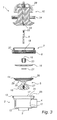
Fig. 2 is a schematic exploded view, seen in perspective from below, of the device inFig. 1 . -
Fig. 3 is a schematic exploded view of a longitudinal section of the device according toFig. 1 or alternativelyFig. 2 . -
Fig. 4a shows a part of a device in a valve, according toFig. 1 , in the mounted state, illustrating a mounting position. -
Fig. 4b shows a part of a device in a valve, according toFig. 1 , in the mounted state, which illustrates a press-fit position. -
Fig. 5a is a longitudinal section of a device in a valve according toFig. 1 , in the mounted state, illustrating an open position. -
Fig. 5b is a longitudinal section of a device in a valve according toFig. 1 , in the mounted state, illustrating a closed position. -
Figs 6a-6c illustrate an alternative embodiment of the device according to the present invention. -
Figs 7a and 7b illustrate another embodiment of the device according to the present invention. -
Figs 8a and8b illustrate another alternative embodiment of the device according to the present invention. -
Fig. 9 shows yet another embodiment of the device according to the present invention. -
Fig. 10 shows a further embodiment of the device according to the present invention. -
Fig. 1 illustrates avalve 1 with a device according to a first preferred embodiment of the invention. Thevalve 1 comprises avalve housing 2 of prior art type, which has an internal, preferably cylindrical cavity. The valve housing has at least a firstfluid port 3 and a secondfluid port 4. The firstfluid port 3 is preferably arranged in alower portion 13 of the valve housing and suitably forms an inlet port, seeFig. 1 . The second fluid port is preferably arranged in the side wall of thevalve housing 2 and suitably forms an outlet port. - A preferably
movable closure element 5 is adapted to be arranged in the cavity of thevalve housing 2. The closure element is preferably rotationally symmetrical with an upper end, a sealingportion 14, adapted to anupper portion 12 of thevalve housing 2. Theclosure element 5 has another sealingportion 15, in this embodiment a lower end, which is adapted to alower portion 13 of thevalve housing 2 to be mutually sealable adjacent the firstfluid port 3 in use. With reference toFig. 2 , the central portion of theclosure element 5 between said ends has a preferably waist-like shape which is adapted to apassage portion 11 adjacent the secondfluid port 4. - With reference to
Fig. 3 , theclosure element 5 has asecond sealing portion 14, in this embodiment an upper end, suitably ahole 27 which extends in the axial direction, downward, into theclosure element 5. Thehole 27 in the closure element is, for instance, internally threaded, which is intended for aconnectable actuator 6. The closure element also has at its upper end 14 a sealingregion 29 which extends circumferentially with an edge inward toward thevalve housing 2. Theclosure element 5 also has aflexible portion 30 which is radially inside said sealingregion 29. - Referring once more to
Fig. 2 , thevalve housing 2 has in its upper portion 12 aconnection opening 17. Theupper portion 12 of thevalve housing 2 is adapted to be connected to acoupling device 7. Thecoupling device 7 is preferably connectable to thevalve housing 2 by a locking means 8. The locking means 8 is suitably provided with an internal thread, which is adapted to a complementary external thread of thevalve housing 2 for mutual locking. - With reference to
Fig. 3 , thecoupling device 7 also suitably has a centrally arrangedhole 19 which is provided with an internal thread. Thehole 19 is adapted to receive athread bushing 20 provided with an external thread. The upper end of thethread bushing 20 is preferably connectable to the hole, (seeFig. 2 ). - The lower end of the
thread bushing 20 is suitably provided with an abutment means 16 which is fastened to be rotatable on the thread bushing. The abutment means 16, which is to be seen inFig. 2 , is arranged inward toward the valve housing. Thethread bushing 20 has preferably at its lower free end a lockingwasher 21 for retaining the abutment means in the intended position. - With reference to
Fig. 3 , thethread bushing 20 has ahexagonal actuating hole 18 intended for an Allen key. Thethread bushing 20 with the rotatably connected abutment means 16 thus is axially adjustable relative to thecoupling device 7 in its threadedhole 19. - Referring once more to
Fig. 3 , it is to be seen that theelongated actuator 6 in its lower end preferably is provided with an external thread to be connected to thehole 27 of theclosure element 5. Furthermore theactuator 6 is in its upper end suitably provided with an internal thread to be connected to and receive anactuating device 10 with an externally threadedpin 23. Theactuator 6 is to be inserted through thehexagonal actuating hole 18 in thethread bushing 20 for the intended connection of the actuator at both ends. The upper end of the actuator can also be provided with adiametrical groove 22 which is used to allow a complementary tool (not shown) to adjust the connection of theactuator 6 to theclosure element 5. - The
actuating device 10 is preferably connectable to thecoupling device 7 by an annular fastening means 24. The fastening means 24 is suitably provided with an internal thread which is adapted to a complementary external thread of thecoupling device 7 for interconnection. - The actuating device can be actuated by manual or pneumatic, hydraulic or electrical control or alternatively a combination thereof.
- The
valve housing 2, thecoupling device 7, the abutment means 16 and theactuator 6 are preferably made of metal, such as stainless steel or aluminium, but may, of course, be made of other materials or combinations of materials that meet the requirements and wishes according to the intentions of the invention. Thethread bushing 20 is suitably made of metal, such as bronze, in order to ensure easy operation of the same and, for instance, allow low friction. - The
closure element 5 according to the first embodiment is preferably made of a flexible polymer, such as Teflon, polytetrafluoroethylene (PTFE). - The
closure element 5 may, of course, be made of other materials that meat the requirements and wishes of the invention, such as rubber or a combination of PTFE and rubber. - The requirements and wishes as to materials that can be placed on the invention may, for example, be chemical resistance, temperature and pressure resistance. These materials and material needs may, of course, be varied in view of the application concerned.
- Components such as the interior of the
valve housing 2, thefluid ports closure element 5, theactuator 6, thecoupling device 7, the abutment means 16 and theconnection opening 17 are substantially circular in cross-section, but may of course have a different shape as long as the objects and requirements of the invention are met. Other conceivable shapes can be oval, square or some kind of regular or irregular polygonal shape. - The mounting of the
valve 1 and the other components will now be described in the following with reference toFigs 3 ,4a and 4b . - As mentioned above, the
valve housing 2 has aconnection opening 17 in theupper portion 12 of the valve housing, seeFig. 3 . In its upper inside, thevalve housing 2 preferably has asupport portion 25 and aseat portion 31. Theclosure element 5 is insertable through theconnection opening 17, an outer radial portion at theupper end 14 of the closure element abutting against thesupport portion 25. - With reference once more to
Fig. 3 , the closure element has preferably at its upper end anedge portion 26 where theclosure element 5 has an indentation with a peripheral edge. It is to be noted that the upper end, the sealingportion 14, of theclosure element 5 in its mounted state preferably is arranged, suitably in a floating manner, at a small radial distance from the inner wall of thevalve housing 2. - The abutment means 16 is connected to the lower end of the
thread bushing 20 suitably by means of the lockingwasher 21. The upper end of the thread bushing is screwed from below into the internally threadedhole 19 of thecoupling device 7. Thus the abutment means 16 is adjustably connected to thecoupling device 7 on the underside thereof by thethread bushing 20. During mounting, the abutment means is in its upper position so as to abut against the underside of the coupling device, which is seen inFig. 4a . - As shown in
Fig. 3 , thecoupling device 7, with the integrated components stated above, is connected to theupper portion 12 of thevalve housing 2 by the locking means 8. - The locking means 8 is preferably an annular nut means. An appropriate tool (not shown) thus suitably performs the connection so that the locking means 8 and the upper
valve housing portion 12 abut against each other in a reliable manner. - With reference to
Figs 4a and 4b , it is to be seen that thethread bushing 20 can be adjusted with thehexagonal actuating hole 18 by means of an Allen key so that the abutment means is adjusted to abut with a press- fit against theclosure element 5. - The Allen key can advantageously be what is referred to as a torque wrench, which ensures that a similar adjusted torque is applied in each press-fit operation which, for example, takes place in connection with maintenance.
- With reference to
Fig. 3 , theactuator 6 is inserted into theactuating hole 18 and screwed into theclosure element 5 by means of an appropriate tool (not shown) which engages in thediametrical groove 22 of theactuator 6. - After that, the actuating device is arranged over the coupling device and rotated so that the
pin 23 is threaded into the upper portion of theactuator 6. The fastening means 24 of theactuating device 10 is then attached by screwing and tightened with an appropriate tool (not shown). - In addition to this description of mounting, the respective fluid ports are of course connected to fluid lines, but since this takes place according to prior art technique and is not a direct part of the invention, this operation is left out of the description.
- The function of the
valve 1 and the other components will now be described in the following with reference toFigs 4a, 4b and5a, 5b respectively. When a mounted device in thevalve 2 according to the present invention is arranged in the intended position, for instance, adjacent a fluid tank for directing the fluid flow, for example the firstfluid port 3 of the valve is connected to the lower portion of the fluid tank as an inlet of the valve. The secondfluid port 4 of the valve is connected to a fluid line as an outlet of the valve. - When a user intends to open the
valve 2 provided with amanual actuating device 10, he turns ahandle 28, seeFigs 5a, 5b . With the handle, thepin 23 is moved in the axial direction from the tank connection of the valve (below referred to as off direction). Thepin 23 actuates theactuator 6 through theactuating hole 18 in the same off direction. - Due to the movement of the
actuator 6, theclosure element 5 moves in the same off direction, seeFig. 5a . The end, the sealingportion 15, of the closure element thus leaves the abutment surfaces of the first fluid port. Any fluid in the tank may thus, for instance due to gravity, flow through the valve. The end, the sealingportion 15, of the closure element, and its waist portions together with the inner walls of thevalve housing 2 between the first 3 and the secondfluid port 4 form theflow passage 11. The fluid can now flow from the firstfluid port 3 through theflow passage 11 to thefluid port 4. - Correspondingly, but in the opposite direction, the closing process of the valve takes place when the handle of the actuating device is turned to the closing position, whereby the first
fluid port 3 is again closed, seeFig. 5b . It is to be noted that in the first embodiment the preferablyrigid closure element 5 suitably flexes about the sealingportion 31 when operating the positions of the valve. - In operation, the
coupling device 7 ensures that the sealingregion 29, together with theseat portion 31 of the valve housing, under the action of the abutment means 16 has the required sealing function. In order to demonstrate leakage in this seal, anindication passage 32 is arranged in thecoupling device 7, seeFig. 3 . - With reference to
Figs 4a, 4b and the above description of mounting, the following occurs when thethread bushing 20 is, for example, adjusted by an Allen key in thehexagonal actuating hole 18. This can preferably occur without the actuator being mounted. - When the abutment means 16 is moved toward the
closure element 5, a preferably uniformly distributed force is peripherally applied between the above components for mutual sealing. This force is suitably transmitted centrally by thethread bushing 20 as force- transmitting means. This single adjusting means results in adjustment being achieved in a simple and uniform manner. In thevalve housing 2, thesupport portion 25 and theseat portion 31 act as an abutment for the closure element so that the abutment means 16 obtains the desired function. In the opposite direction, thecoupling device 7 together with thethread bushing 20 acts as an abutment for the press-fit force exerted by the abutment means 16. - The abutment means 16 preferably exerts a pressure, at a suitable radial distance from its centre, on the
closure element 5 adjacent theedge portion 26. This distance is adjusted so that theclosure element 5 can flex adjacent theflexible portion 30 for actuating thevalve 1. In other words, the closure element has adjacent saidportion 30 at the end, the sealingportion 14, some freedom of movement so that the closure element can move in the intended vertical direction. - The abutment means 16 preferably abuts on both sides of the
edge portion 26 of theclosure element 5 to ensure adequate abutment. This press-fit abutment force results in the desired sealing function between the sealingregion 29 and theseat portion 31. The invention according to the second embodiment will now be described. Theclosure element 5 has a shape which is preferably adapted to the abutment means 16. Theclosure element 5 according to the second embodiment is suitably made of a resilient soft material, such as silicone, ethylene-propylene rubber (EPDM), fluorinated rubber (FPM; viton).
Theclosure element 5 can, of course, be made of another material which has the properties that are required according to the intentions of the invention. - The
above closure element 5 can have, for example, a metal core which is directly or indirectly connectable to theactuating device 10. Theclosure element 5 preferably has good sealing properties independently of pressure and temperature changes, the abutment means 16 being pressed directly against theclosure element 5, whereby sealing occurs between the sealingregion 29 and theseat portion 31. - In
Figs 1-5 , the abutment means 16 is a resilient
washer. The subsequent figures illustrate alternative spring means in the different embodiment of the valve. -
Figs 6a-6c illustrate an alternative embodiment of the device according to the present invention. The abutment means 16 is pressed against theclosure element 5 by acompression spring 35, which ensures that a pressure is exerted by the abutment means 16 on theclosure element 5 in changes of the size of the parts included in the device.Fig. 6a shows the valve in the closed position, andFigs 6b and 6c in the open position. InFigs 6c , thespring 35 is slightly more tensioned than inFig. 6b . The compression of thespring 35 is in this embodiment performed by an adjustingscrew 6, aworm gear 33, anut 34 and thethread bushing 20. An advantage of this embodiment is that thespring 35 can be tensioned without necessitating dismounting of any part of the valve. - In
Figs 7a and 7b , which illustrate a further embodiment of the device according to the present invention, the abutment means comprises aspring washer 36 which just like thecompression spring 35 inFig. 6a-6c ensures that a pressure is exerted by the abutment means 16 on theclosure element 5 in changes of the size of the parts included in the device.Fig. 7a shows the device in one position with a large expansion gap, andFig. 7b in another position with a small expansion gap. - Yet another alternative embodiment of the device according to the invention is shown in
Figs 8a (open valve) and 8b (closed valve). In this embodiment, the abutment means is acompression spring 35, which is to be tensioned by thethread bushing 20. In this embodiment, the "cone" is shown as a separate part which is arranged by means of a bolt with the diaphragm part of theclosure element 5. - Another embodiment of the device according to the present invention is shown is
Fig. 9 , where theclosure element 5 largely consists of a diaphragm which is pressed down against aridge 37 belonging to thevalve housing 2 in order to close the valve. Thediaphragm 5 is sealed against thevalve housing 2 by a number ofbolts 38 holding an abutment means 16 against the peripheral portions of the diaphragm. In addition, aspring 35 is arranged adjacent each bolt to maintain a minimum sealing force independently of the movements of the components due to temperature.Fig. 10 shows the same valve as inFig. 9 but with an alternative spring action involving an abutment means which at the same time is acompression spring 35. Thecompression spring 35 is pressed down against thediaphragm 35 by an adjustable means (not shown) close to the centre of thecompression spring 35. - It will be appreciated that the above described embodiments of the present invention can be modified and varied by as person skilled in the art, without departing from the inventive concept defined in the claims. For instance, the valve and its components according to the present invention with the various fastening means, locking means, thread bushings can, of course, be provided in various ways such as detachable joints (for instance screw, spline, key, clamp, press and shrink joints) or alternative other elastic joints or power joints, but also in some applications, permanent joints (weld, glue and rivet joints). It goes without saying that it is also possible to combine the various spring alternatives. For example, the valve with its components may consist of several parts both as separate or composite components, such as several fluid ports, valve housings, closure elements, abutment means, coupling devices, thread bushings. The above-mentioned components can also be integrated when convenient and when allowed by the application.
-
- 1.
- valve
- 2.
- valve housing
- 3.
- first fluid port, fluid opening
- 4.
- second fluid port, fluid side opening
- 5.
- closure element
- 6.
- actuator
- 7.
- coupling device
- 8.
- locking means (coupling device)
- 9.
- adjusting screw
- 10.
- actuating device
- 11.
- flow passage, passage portion
- 12.
- upper portion valve housing
- 13.
- lower portion valve housing
- 14.
- sealing portion
- 15.
- sealing portion
- 16.
- abutment means; abutment portion
- 17.
- connection opening
- 18.
- actuating hole
- 19.
- hole coupling device
- 20.
- thread bushing
- 21.
- locking washer
- 22.
- groove in actuator
- 23.
- pin actuating device
- 24.
- fastening means (actuating device)
- 25.
- support portion (valve housing)
- 26.
- edge portion
- 27.
- hole in closure element
- 28.
- handle (actuating device)
- 29.
- sealing region
- 30.
- flexible portion
- 31.
- seat portion
- 32.
- indication passage
- 33.
- worm gear
- 34.
- nut
- 35.
- compression spring
- 36.
- spring washer
- 37.
- ridge
- 38.
- bolt
Claims (10)
- A device in a valve (1) comprising a valve housing (2) with at least a first (3) and a second (4) fluid port, a closure element (5) being arranged in the valve housing (2), which closure element (5) has a sealing portion (15) and comprises a diaphragm (30), the sealing portion (15) being movable along an axis of the closure element (5) by means of said diaphragm (30) between an open position and a closed position of at least one of the fluid ports of the valve housing, the closure element (5) together with the valve housing (2) forming a flow passage (11) in the valve housing (2) which communicates with said fluid ports when the sealing portion (15) leaves said closed position, a second sealing portion (14) of the closure element, which is an enclosing portion spaced-apart from said axis, being arranged in contact with a support portion (25) of the valve housing (2), an abutment means (16) being arranged in contact along the periphery of said second sealing portion (14) in such manner that said second sealing portion (14) is arranged between the support portion (25) and the abutment means (16), the abutment means (16) being arranged to transmit a force via said second sealing portion (14) towards the support portion (25) to provide a seal, characterised in that said abutment means (16) is a spring means.
- A device as claimed in claim 1, wherein said spring means is chosen from the group of torsions springs and resilient springs with bending action.
- A device as claimed in any one of claims 1 and 2, in which a pressure spring (35) is arranged so as to provide a compressive force parallel with said axis.
- A device as claimed in any one of claims 1 to 3, in which a spring washer (36) is arranged so as to provide a compressive force parallel with said axis.
- A device as claimed in any one of claims 1 to 4, in which the abutment means is a spring washer (35).
- A device as claimed in any one of claims 1 to 5, in which said second sealing portion (15) of the closure element (5) has a sealing region (29) and the valve housing (2) has a complementary seat portion (31) for mutual sealing.
- A device as claimed in any one of claims 1 to 6, in which the sealing portion (15) of the closure element (5) is operably connected by an actuator (6), the device having a coupling device (7) which has a locking means (8) adapted to be arranged to the valve housing (2) and an actuating device (10) adapted to be connected to the coupling device (7) to operate the actuator (6).
- A device as claimed in any one of claims 6 and 7, in which the actuator (6) is elongate and arranged so that its longitudinal axis coincides with said axis of the closure element (5) and further arranged in an actuator recess (18) through a recess (19) in the coupling device (7).
- A device as claimed in any one of claims 7 and 8, in which the abutment means (16) is adjustably arranged in the coupling device (7) by means of a thread bushing (20).
- A device as claimed in claim 9, in which the thread bushing (20) is externally threaded and connected to the recess (19) in the coupling device (7).
Applications Claiming Priority (1)
| Application Number | Priority Date | Filing Date | Title |
|---|---|---|---|
| SE0700265A SE532056C2 (en) | 2007-02-02 | 2007-02-02 | valve seal |
Publications (3)
| Publication Number | Publication Date |
|---|---|
| EP1953436A2 true EP1953436A2 (en) | 2008-08-06 |
| EP1953436A3 EP1953436A3 (en) | 2010-07-07 |
| EP1953436B1 EP1953436B1 (en) | 2012-11-07 |
Family
ID=39367558
Family Applications (1)
| Application Number | Title | Priority Date | Filing Date |
|---|---|---|---|
| EP08150093A Active EP1953436B1 (en) | 2007-02-02 | 2008-01-08 | Valve seal |
Country Status (7)
| Country | Link |
|---|---|
| US (4) | US7980531B2 (en) |
| EP (1) | EP1953436B1 (en) |
| JP (2) | JP5003962B2 (en) |
| CN (1) | CN101240854B (en) |
| ES (1) | ES2396990T3 (en) |
| SE (1) | SE532056C2 (en) |
| SG (2) | SG178739A1 (en) |
Cited By (2)
| Publication number | Priority date | Publication date | Assignee | Title |
|---|---|---|---|---|
| WO2013170931A1 (en) * | 2012-05-15 | 2013-11-21 | Gea Tuchenhagen Gmbh | Valve and diaphragm for a valve |
| DE102016115638A1 (en) | 2016-08-23 | 2018-03-01 | Gemü Gebr. Müller Apparatebau Gmbh & Co. Kommanditgesellschaft | diaphragm valve |
Families Citing this family (16)
| Publication number | Priority date | Publication date | Assignee | Title |
|---|---|---|---|---|
| EP2292297B1 (en) | 2002-04-26 | 2020-06-03 | EMD Millipore Corporation | Disposable steam sterilisable medical valve |
| US7293477B2 (en) | 2003-12-23 | 2007-11-13 | Millipore Corporation | Disposable, pre-sterilized fluid receptacle sampling device |
| SG153002A1 (en) | 2007-11-16 | 2009-06-29 | Millipore Corp | Fluid transfer device |
| FR2940439B1 (en) | 2008-12-18 | 2011-02-11 | Millipore Corp | DEVICE FOR TRANSFERRING A MEDIUM |
| FR2940440B1 (en) | 2008-12-18 | 2010-12-24 | Millipore Corp | DEVICE FOR TRANSFERRING A MEDIUM |
| US8544497B2 (en) | 2009-10-30 | 2013-10-01 | Emd Millipore Corporation | Fluid transfer device and system |
| DK177973B1 (en) * | 2013-09-09 | 2015-02-09 | Broen As | Method of manufacturing a valve housing with spindle and valve housing |
| CN103672019A (en) * | 2013-12-02 | 2014-03-26 | 东正科技有限公司 | Sterile diaphragm valve |
| US20170050777A1 (en) * | 2014-05-09 | 2017-02-23 | Davy Zide Qian | Diaphragm Valve Soda Dispenser |
| EP3215438B1 (en) | 2014-11-04 | 2019-06-19 | Klean Kanteen, Inc. | Container sealing assembly |
| DE102015005692A1 (en) * | 2015-05-06 | 2016-11-10 | Mann + Hummel Gmbh | Pressure control valve |
| CN106783380A (en) * | 2016-12-19 | 2017-05-31 | 上海上芃电气有限公司 | A kind of SF6Density monitor |
| KR102561519B1 (en) * | 2018-12-18 | 2023-08-01 | 엔테그리스, 아이엔씨. | Valves and valve elements for controlling fluid flow |
| CN109611579B (en) * | 2019-02-20 | 2024-03-29 | 九牧厨卫股份有限公司 | Flow valve |
| SG11202108694VA (en) * | 2019-02-20 | 2021-09-29 | Itt Mfg Enterprises Llc | Keying structure |
| CA3231495A1 (en) | 2021-09-15 | 2023-03-23 | Sanisure, Inc. | Low volume magnetic mixing system |
Family Cites Families (39)
| Publication number | Priority date | Publication date | Assignee | Title |
|---|---|---|---|---|
| US2665105A (en) * | 1946-09-07 | 1954-01-05 | Crane Co | Diaphragm sealed valve |
| US2638307A (en) * | 1947-11-22 | 1953-05-12 | Fortune Ronald | Diaphragm valve |
| US2679378A (en) * | 1949-10-27 | 1954-05-25 | White S Dental Mfg Co | High-pressure valve |
| US2895497A (en) * | 1956-04-18 | 1959-07-21 | Henry Valve Company Inc | Packless valve |
| US3192942A (en) * | 1961-08-15 | 1965-07-06 | Rockwell Mfg Co | Plug valve assembly |
| US3371676A (en) * | 1965-06-18 | 1968-03-05 | Grinnell Corp | Lubricated plug valve with adjustable uniform sealing pressure gland |
| FR1468804A (en) * | 1965-09-15 | 1967-02-10 | Ferodo Sa | Improvements to automatically controlled valves, in particular for regulating the heating of motor vehicles |
| DE2341858C2 (en) * | 1973-08-18 | 1975-09-11 | Danfoss A/S, Nordborg (Daenemark) | Valve with a diaphragm actuated locking mechanism |
| JPS5055628U (en) * | 1973-09-18 | 1975-05-26 | ||
| JPS5079933A (en) * | 1973-11-16 | 1975-06-28 | ||
| US4228816A (en) * | 1978-01-04 | 1980-10-21 | Jamesbury Corporation | Fire safe butterfly valve |
| US4354666A (en) * | 1980-06-12 | 1982-10-19 | Kerotest Manufacturing Corp. | High pressure packless metal diaphragm valve |
| US4635683A (en) * | 1985-10-03 | 1987-01-13 | Ford Motor Company | Variable force solenoid |
| DE3808671A1 (en) * | 1987-03-13 | 1988-09-22 | Orbital Eng Pty | DEVICE AND METHOD FOR INJECTING FUEL |
| JPH0193674A (en) * | 1987-10-02 | 1989-04-12 | Koganei Seisakusho:Kk | Valve |
| JPH0615184Y2 (en) * | 1988-11-29 | 1994-04-20 | マルヤス工業株式会社 | Diaphragm valve |
| US5024453A (en) * | 1988-12-20 | 1991-06-18 | Pressure Services, Inc. | Liveload assembly for rotary or reciprocating shaft packing |
| CH683364A5 (en) * | 1991-06-07 | 1994-02-28 | Fischer Georg Rohrleitung | Diaphragm valve. |
| US5192049A (en) * | 1992-06-12 | 1993-03-09 | Cashco, Inc. | Dual rated live loaded packing system for a valve stem |
| GB2271163B (en) * | 1992-10-02 | 1996-09-04 | Latty International Ltd | Valve assembly and spring assembly for use therein |
| US5326074A (en) * | 1992-11-06 | 1994-07-05 | Xomox Corporation | Enhanced sealing arrangement for a rotary valve shaft |
| JPH084918A (en) * | 1994-06-17 | 1996-01-12 | Hitachi Metals Ltd | Diaphragm seal valve and metallic diaphragm thereof |
| US5449142A (en) * | 1994-12-12 | 1995-09-12 | Automatic Switch Company | Two-way cartridge valve for aggresive media |
| ATE253699T1 (en) * | 1999-06-08 | 2003-11-15 | Tuchenhagen Gmbh | SHOOTING ELEMENT UNIT FOR AN ASEPTIC DOUBLE SEAT VALVE |
| WO2001033126A1 (en) | 1999-11-03 | 2001-05-10 | Tuchenhagen Gmbh | Device for the torque-free operation of a closing member for a lift valve |
| DE29919298U1 (en) * | 1999-11-03 | 2000-01-13 | Tuchenhagen Gmbh | Device for the torque-free actuation of a closing element for a lift valve |
| JP2001263508A (en) | 2000-03-17 | 2001-09-26 | Neriki:Kk | Diaphragm type valve |
| DE60223345T2 (en) * | 2001-02-20 | 2008-08-28 | Nl Technologies, Ltd. | DIAPHRAGM VALVE WITH COMPRESSIVE SEAL |
| JP2002295693A (en) * | 2001-03-28 | 2002-10-09 | Fujikura Rubber Ltd | Control valve, and manufacturing method of valve element for the control valve |
| US7232106B2 (en) * | 2001-04-04 | 2007-06-19 | Kah Jr Carl | Tilted and stepped diaphragm for control valves |
| PT1440265E (en) * | 2001-10-29 | 2008-08-26 | Bermad Ltd Partnership | Roll diaphragm control valve |
| EP1527296B1 (en) * | 2002-08-06 | 2010-10-06 | Fedegari Autoclavi Spa | Sanitary diaphragm valve |
| US6994319B2 (en) * | 2003-01-29 | 2006-02-07 | Applied Materials, Inc. | Membrane gas valve for pulsing a gas |
| CN100381732C (en) | 2003-07-11 | 2008-04-16 | 安堤格里斯公司 | Extended stroke valve and diaphragm |
| US7063304B2 (en) | 2003-07-11 | 2006-06-20 | Entegris, Inc. | Extended stroke valve and diaphragm |
| JP2008190546A (en) * | 2007-01-31 | 2008-08-21 | Iwai Kikai Kogyo Co Ltd | Diaphragm fixing structure of diaphragm valve |
| US8602052B2 (en) * | 2010-06-22 | 2013-12-10 | Swagelok Company | Clamp ring for welded diaphragms |
| US8714517B2 (en) * | 2010-09-20 | 2014-05-06 | Fisher Controls International, Llc | Bonnet apparatus to provide live-loading to a seal |
| US9494237B2 (en) * | 2013-05-20 | 2016-11-15 | Teadit N.A., Inc. | Compressible packing live loading apparatus |
-
2007
- 2007-02-02 SE SE0700265A patent/SE532056C2/en unknown
-
2008
- 2008-01-08 ES ES08150093T patent/ES2396990T3/en active Active
- 2008-01-08 EP EP08150093A patent/EP1953436B1/en active Active
- 2008-01-16 SG SG2012007282A patent/SG178739A1/en unknown
- 2008-01-16 SG SG200800235-4A patent/SG144829A1/en unknown
- 2008-01-31 JP JP2008020455A patent/JP5003962B2/en active Active
- 2008-01-31 CN CN2008100092402A patent/CN101240854B/en active Active
- 2008-02-01 US US12/068,096 patent/US7980531B2/en active Active
-
2011
- 2011-04-14 US US13/087,201 patent/US8919733B2/en active Active
-
2012
- 2012-04-06 JP JP2012087439A patent/JP5354228B2/en active Active
-
2014
- 2014-11-26 US US14/554,855 patent/US9709176B2/en active Active
-
2017
- 2017-01-18 US US15/408,819 patent/US20170122442A1/en not_active Abandoned
Non-Patent Citations (1)
| Title |
|---|
| None |
Cited By (5)
| Publication number | Priority date | Publication date | Assignee | Title |
|---|---|---|---|---|
| WO2013170931A1 (en) * | 2012-05-15 | 2013-11-21 | Gea Tuchenhagen Gmbh | Valve and diaphragm for a valve |
| US9347568B2 (en) | 2012-05-15 | 2016-05-24 | Gea Tuchenhagen Gmbh | Valve and diaphragm for a valve |
| DE102016115638A1 (en) | 2016-08-23 | 2018-03-01 | Gemü Gebr. Müller Apparatebau Gmbh & Co. Kommanditgesellschaft | diaphragm valve |
| CN107763244A (en) * | 2016-08-23 | 2018-03-06 | 盖米工业设备有限两合公司 | Diaphragm valve |
| US10337632B2 (en) | 2016-08-23 | 2019-07-02 | Gemue Gebr. Mueller Apparatebau Gmbh & Co. Kommanditgesellschaft | Diaphragm valve |
Also Published As
| Publication number | Publication date |
|---|---|
| US8919733B2 (en) | 2014-12-30 |
| US20150198256A1 (en) | 2015-07-16 |
| US20170122442A1 (en) | 2017-05-04 |
| SG178739A1 (en) | 2012-03-29 |
| SG144829A1 (en) | 2008-08-28 |
| EP1953436A3 (en) | 2010-07-07 |
| SE0700265L (en) | 2008-08-03 |
| JP2008190716A (en) | 2008-08-21 |
| US9709176B2 (en) | 2017-07-18 |
| JP5003962B2 (en) | 2012-08-22 |
| SE532056C2 (en) | 2009-10-13 |
| US7980531B2 (en) | 2011-07-19 |
| CN101240854A (en) | 2008-08-13 |
| US20110186766A1 (en) | 2011-08-04 |
| JP5354228B2 (en) | 2013-11-27 |
| JP2012163210A (en) | 2012-08-30 |
| EP1953436B1 (en) | 2012-11-07 |
| US20080185552A1 (en) | 2008-08-07 |
| CN101240854B (en) | 2011-11-02 |
| ES2396990T3 (en) | 2013-03-01 |
Similar Documents
| Publication | Publication Date | Title |
|---|---|---|
| US9709176B2 (en) | Device for a valve having first and second fluid ports, including a closure element | |
| US6145810A (en) | Aseptic valve construction with diaphragm having straight neck | |
| US5592965A (en) | Valve stop changer | |
| US20100230963A1 (en) | Retaining ring for pressure vessel connection | |
| JPS62288786A (en) | Diaphragm valve | |
| KR20190016038A (en) | Valves with self-aligned stem tips | |
| EP1610044B1 (en) | A fluid cutoff device | |
| US4630629A (en) | Valve with compressible valve stem and valve body seals | |
| US7971854B2 (en) | Replaceable valve shaft sealing system | |
| US20060096908A1 (en) | Device for filtering fluids that are conveyed under a high presure | |
| JP2740864B2 (en) | Drain valve | |
| US6976664B2 (en) | Free flow valve and element | |
| US7717136B2 (en) | Pipeline closing apparatus | |
| JP5528046B2 (en) | Ball valve | |
| US4276899A (en) | Faucets | |
| JP2559130Y2 (en) | Packing holding jig | |
| KR100300925B1 (en) | Ball valve for opening and shutting of high voltage fluid | |
| KR0181709B1 (en) | Screw valve | |
| AU2004286001B2 (en) | Adjustable sealing means | |
| CA1096844A (en) | Faucets | |
| US20100054641A1 (en) | Actuator mount assembly | |
| CA1096841A (en) | Faucets | |
| EP0046041A1 (en) | Fluid control valve | |
| GB2081424A (en) | Fluid control valve | |
| DE10204722A1 (en) | Membrane valve for pipeline systems for high purity applications, e.g. the semiconducting industry, has screw connections with spring screws with spring and threaded regions |
Legal Events
| Date | Code | Title | Description |
|---|---|---|---|
| PUAI | Public reference made under article 153(3) epc to a published international application that has entered the european phase |
Free format text: ORIGINAL CODE: 0009012 |
|
| AK | Designated contracting states |
Kind code of ref document: A2 Designated state(s): AT BE BG CH CY CZ DE DK EE ES FI FR GB GR HR HU IE IS IT LI LT LU LV MC MT NL NO PL PT RO SE SI SK TR |
|
| AX | Request for extension of the european patent |
Extension state: AL BA MK RS |
|
| PUAL | Search report despatched |
Free format text: ORIGINAL CODE: 0009013 |
|
| AK | Designated contracting states |
Kind code of ref document: A3 Designated state(s): AT BE BG CH CY CZ DE DK EE ES FI FR GB GR HR HU IE IS IT LI LT LU LV MC MT NL NO PL PT RO SE SI SK TR |
|
| AX | Request for extension of the european patent |
Extension state: AL BA MK RS |
|
| 17P | Request for examination filed |
Effective date: 20101215 |
|
| AKX | Designation fees paid |
Designated state(s): AT BE BG CH CY CZ DE DK EE ES FI FR GB GR HR HU IE IS IT LI LT LU LV MC MT NL NO PL PT RO SE SI SK TR |
|
| RIC1 | Information provided on ipc code assigned before grant |
Ipc: F16K 41/12 20060101ALI20110331BHEP Ipc: F16K 41/10 20060101AFI20110331BHEP |
|
| 17Q | First examination report despatched |
Effective date: 20110609 |
|
| GRAP | Despatch of communication of intention to grant a patent |
Free format text: ORIGINAL CODE: EPIDOSNIGR1 |
|
| GRAS | Grant fee paid |
Free format text: ORIGINAL CODE: EPIDOSNIGR3 |
|
| GRAA | (expected) grant |
Free format text: ORIGINAL CODE: 0009210 |
|
| AK | Designated contracting states |
Kind code of ref document: B1 Designated state(s): AT BE BG CH CY CZ DE DK EE ES FI FR GB GR HR HU IE IS IT LI LT LU LV MC MT NL NO PL PT RO SE SI SK TR |
|
| RAP1 | Party data changed (applicant data changed or rights of an application transferred) |
Owner name: MILLIPORE AB |
|
| REG | Reference to a national code |
Ref country code: GB Ref legal event code: FG4D |
|
| REG | Reference to a national code |
Ref country code: CH Ref legal event code: EP Ref country code: AT Ref legal event code: REF Ref document number: 583150 Country of ref document: AT Kind code of ref document: T Effective date: 20121115 |
|
| REG | Reference to a national code |
Ref country code: IE Ref legal event code: FG4D |
|
| REG | Reference to a national code |
Ref country code: DE Ref legal event code: R096 Ref document number: 602008019915 Country of ref document: DE Effective date: 20130103 |
|
| REG | Reference to a national code |
Ref country code: CH Ref legal event code: NV Representative=s name: OFFICE ERNEST T. FREYLINGER S.A., CH |
|
| REG | Reference to a national code |
Ref country code: CH Ref legal event code: NV Representative=s name: OFFICE ERNEST T. FREYLINGER S.A., CH |
|
| REG | Reference to a national code |
Ref country code: ES Ref legal event code: FG2A Ref document number: 2396990 Country of ref document: ES Kind code of ref document: T3 Effective date: 20130301 |
|
| REG | Reference to a national code |
Ref country code: NL Ref legal event code: T3 |
|
| REG | Reference to a national code |
Ref country code: AT Ref legal event code: MK05 Ref document number: 583150 Country of ref document: AT Kind code of ref document: T Effective date: 20121107 |
|
| REG | Reference to a national code |
Ref country code: LT Ref legal event code: MG4D |
|
| PG25 | Lapsed in a contracting state [announced via postgrant information from national office to epo] |
Ref country code: FI Free format text: LAPSE BECAUSE OF FAILURE TO SUBMIT A TRANSLATION OF THE DESCRIPTION OR TO PAY THE FEE WITHIN THE PRESCRIBED TIME-LIMIT Effective date: 20121107 Ref country code: LT Free format text: LAPSE BECAUSE OF FAILURE TO SUBMIT A TRANSLATION OF THE DESCRIPTION OR TO PAY THE FEE WITHIN THE PRESCRIBED TIME-LIMIT Effective date: 20121107 Ref country code: NO Free format text: LAPSE BECAUSE OF FAILURE TO SUBMIT A TRANSLATION OF THE DESCRIPTION OR TO PAY THE FEE WITHIN THE PRESCRIBED TIME-LIMIT Effective date: 20130207 Ref country code: SE Free format text: LAPSE BECAUSE OF FAILURE TO SUBMIT A TRANSLATION OF THE DESCRIPTION OR TO PAY THE FEE WITHIN THE PRESCRIBED TIME-LIMIT Effective date: 20121107 Ref country code: HR Free format text: LAPSE BECAUSE OF FAILURE TO SUBMIT A TRANSLATION OF THE DESCRIPTION OR TO PAY THE FEE WITHIN THE PRESCRIBED TIME-LIMIT Effective date: 20121107 Ref country code: IS Free format text: LAPSE BECAUSE OF FAILURE TO SUBMIT A TRANSLATION OF THE DESCRIPTION OR TO PAY THE FEE WITHIN THE PRESCRIBED TIME-LIMIT Effective date: 20130307 |
|
| PG25 | Lapsed in a contracting state [announced via postgrant information from national office to epo] |
Ref country code: LV Free format text: LAPSE BECAUSE OF FAILURE TO SUBMIT A TRANSLATION OF THE DESCRIPTION OR TO PAY THE FEE WITHIN THE PRESCRIBED TIME-LIMIT Effective date: 20121107 Ref country code: CY Free format text: LAPSE BECAUSE OF FAILURE TO SUBMIT A TRANSLATION OF THE DESCRIPTION OR TO PAY THE FEE WITHIN THE PRESCRIBED TIME-LIMIT Effective date: 20121107 Ref country code: GR Free format text: LAPSE BECAUSE OF FAILURE TO SUBMIT A TRANSLATION OF THE DESCRIPTION OR TO PAY THE FEE WITHIN THE PRESCRIBED TIME-LIMIT Effective date: 20130208 Ref country code: PL Free format text: LAPSE BECAUSE OF FAILURE TO SUBMIT A TRANSLATION OF THE DESCRIPTION OR TO PAY THE FEE WITHIN THE PRESCRIBED TIME-LIMIT Effective date: 20121107 Ref country code: PT Free format text: LAPSE BECAUSE OF FAILURE TO SUBMIT A TRANSLATION OF THE DESCRIPTION OR TO PAY THE FEE WITHIN THE PRESCRIBED TIME-LIMIT Effective date: 20130307 Ref country code: SI Free format text: LAPSE BECAUSE OF FAILURE TO SUBMIT A TRANSLATION OF THE DESCRIPTION OR TO PAY THE FEE WITHIN THE PRESCRIBED TIME-LIMIT Effective date: 20121107 |
|
| PG25 | Lapsed in a contracting state [announced via postgrant information from national office to epo] |
Ref country code: AT Free format text: LAPSE BECAUSE OF FAILURE TO SUBMIT A TRANSLATION OF THE DESCRIPTION OR TO PAY THE FEE WITHIN THE PRESCRIBED TIME-LIMIT Effective date: 20121107 |
|
| PG25 | Lapsed in a contracting state [announced via postgrant information from national office to epo] |
Ref country code: DK Free format text: LAPSE BECAUSE OF FAILURE TO SUBMIT A TRANSLATION OF THE DESCRIPTION OR TO PAY THE FEE WITHIN THE PRESCRIBED TIME-LIMIT Effective date: 20121107 Ref country code: BG Free format text: LAPSE BECAUSE OF FAILURE TO SUBMIT A TRANSLATION OF THE DESCRIPTION OR TO PAY THE FEE WITHIN THE PRESCRIBED TIME-LIMIT Effective date: 20130207 Ref country code: EE Free format text: LAPSE BECAUSE OF FAILURE TO SUBMIT A TRANSLATION OF THE DESCRIPTION OR TO PAY THE FEE WITHIN THE PRESCRIBED TIME-LIMIT Effective date: 20121107 Ref country code: SK Free format text: LAPSE BECAUSE OF FAILURE TO SUBMIT A TRANSLATION OF THE DESCRIPTION OR TO PAY THE FEE WITHIN THE PRESCRIBED TIME-LIMIT Effective date: 20121107 Ref country code: CZ Free format text: LAPSE BECAUSE OF FAILURE TO SUBMIT A TRANSLATION OF THE DESCRIPTION OR TO PAY THE FEE WITHIN THE PRESCRIBED TIME-LIMIT Effective date: 20121107 |
|
| PG25 | Lapsed in a contracting state [announced via postgrant information from national office to epo] |
Ref country code: MC Free format text: LAPSE BECAUSE OF NON-PAYMENT OF DUE FEES Effective date: 20130131 Ref country code: RO Free format text: LAPSE BECAUSE OF FAILURE TO SUBMIT A TRANSLATION OF THE DESCRIPTION OR TO PAY THE FEE WITHIN THE PRESCRIBED TIME-LIMIT Effective date: 20121107 |
|
| PLBE | No opposition filed within time limit |
Free format text: ORIGINAL CODE: 0009261 |
|
| STAA | Information on the status of an ep patent application or granted ep patent |
Free format text: STATUS: NO OPPOSITION FILED WITHIN TIME LIMIT |
|
| 26N | No opposition filed |
Effective date: 20130808 |
|
| REG | Reference to a national code |
Ref country code: IE Ref legal event code: MM4A |
|
| REG | Reference to a national code |
Ref country code: DE Ref legal event code: R097 Ref document number: 602008019915 Country of ref document: DE Effective date: 20130808 |
|
| PG25 | Lapsed in a contracting state [announced via postgrant information from national office to epo] |
Ref country code: IE Free format text: LAPSE BECAUSE OF NON-PAYMENT OF DUE FEES Effective date: 20130108 |
|
| PG25 | Lapsed in a contracting state [announced via postgrant information from national office to epo] |
Ref country code: MT Free format text: LAPSE BECAUSE OF FAILURE TO SUBMIT A TRANSLATION OF THE DESCRIPTION OR TO PAY THE FEE WITHIN THE PRESCRIBED TIME-LIMIT Effective date: 20121107 |
|
| REG | Reference to a national code |
Ref country code: CH Ref legal event code: NV Representative=s name: NOVAGRAAF INTERNATIONAL SA, CH Ref country code: CH Ref legal event code: PFA Owner name: MERCK CHEMICALS AND LIFE SCIENCE AB, SE Free format text: FORMER OWNER: MILLIPORE AB, SE |
|
| PG25 | Lapsed in a contracting state [announced via postgrant information from national office to epo] |
Ref country code: TR Free format text: LAPSE BECAUSE OF FAILURE TO SUBMIT A TRANSLATION OF THE DESCRIPTION OR TO PAY THE FEE WITHIN THE PRESCRIBED TIME-LIMIT Effective date: 20121107 |
|
| REG | Reference to a national code |
Ref country code: ES Ref legal event code: PC2A Owner name: MERCK CHEMICALS AND LIFE SCIENCE AB Effective date: 20150630 |
|
| REG | Reference to a national code |
Ref country code: DE Ref legal event code: R081 Ref document number: 602008019915 Country of ref document: DE Owner name: MERCK CHEMICALS AND LIFE SCIENCE AB, SE Free format text: FORMER OWNER: MILLIPORE AB, SOLNA, SE |
|
| PG25 | Lapsed in a contracting state [announced via postgrant information from national office to epo] |
Ref country code: HU Free format text: LAPSE BECAUSE OF FAILURE TO SUBMIT A TRANSLATION OF THE DESCRIPTION OR TO PAY THE FEE WITHIN THE PRESCRIBED TIME-LIMIT; INVALID AB INITIO Effective date: 20080108 Ref country code: LU Free format text: LAPSE BECAUSE OF NON-PAYMENT OF DUE FEES Effective date: 20130108 |
|
| REG | Reference to a national code |
Ref country code: NL Ref legal event code: TD Effective date: 20150805 |
|
| REG | Reference to a national code |
Ref country code: FR Ref legal event code: CD Owner name: MERCK CHEMICALS AND LIFE SCIENCE AB, SE Effective date: 20150908 Ref country code: FR Ref legal event code: CA Effective date: 20150908 |
|
| REG | Reference to a national code |
Ref country code: FR Ref legal event code: PLFP Year of fee payment: 9 |
|
| REG | Reference to a national code |
Ref country code: FR Ref legal event code: PLFP Year of fee payment: 10 |
|
| REG | Reference to a national code |
Ref country code: FR Ref legal event code: PLFP Year of fee payment: 11 |
|
| REG | Reference to a national code |
Ref country code: ES Ref legal event code: PC2A Owner name: MERCK LIFE SCIENCE AB Effective date: 20220927 |
|
| PGFP | Annual fee paid to national office [announced via postgrant information from national office to epo] |
Ref country code: BE Payment date: 20221216 Year of fee payment: 16 |
|
| PGFP | Annual fee paid to national office [announced via postgrant information from national office to epo] |
Ref country code: ES Payment date: 20230209 Year of fee payment: 16 Ref country code: CH Payment date: 20230106 Year of fee payment: 16 |
|
| PGFP | Annual fee paid to national office [announced via postgrant information from national office to epo] |
Ref country code: IT Payment date: 20221213 Year of fee payment: 16 Ref country code: DE Payment date: 20221207 Year of fee payment: 16 |
|
| P01 | Opt-out of the competence of the unified patent court (upc) registered |
Effective date: 20230602 |
|
| REG | Reference to a national code |
Ref country code: BE Ref legal event code: HC Owner name: MERCK CHEMICALS AND LIFE SCIENCE AB; SE Free format text: DETAILS ASSIGNMENT: CHANGE OF OWNER(S), CHANGE OF OWNER(S) NAME; FORMER OWNER NAME: MILLIPORE AB Effective date: 20230414 |
|
| PGFP | Annual fee paid to national office [announced via postgrant information from national office to epo] |
Ref country code: GB Payment date: 20231207 Year of fee payment: 17 |
|
| PGFP | Annual fee paid to national office [announced via postgrant information from national office to epo] |
Ref country code: NL Payment date: 20231215 Year of fee payment: 17 Ref country code: FR Payment date: 20231212 Year of fee payment: 17 |
|
| REG | Reference to a national code |
Ref country code: BE Ref legal event code: HC Owner name: MERCK LIFE SCIENCE AB; SE Free format text: DETAILS ASSIGNMENT: CHANGE OF OWNER(S), CHANGE OF OWNER(S) NAME; FORMER OWNER NAME: MERCK CHEMICALS AND LIFE SCIENCE AB Effective date: 20240109 |
|
| REG | Reference to a national code |
Ref country code: DE Ref legal event code: R081 Ref document number: 602008019915 Country of ref document: DE Owner name: MERCK LIFE SCIENCE AB, SE Free format text: FORMER OWNER: MERCK CHEMICALS AND LIFE SCIENCE AB, SOLNA, SE |
|
| PGFP | Annual fee paid to national office [announced via postgrant information from national office to epo] |
Ref country code: BE Payment date: 20231219 Year of fee payment: 17 |
|
| REG | Reference to a national code |
Ref country code: NL Ref legal event code: HC Owner name: MERCK LIFE SCIENCE AB; SE Free format text: DETAILS ASSIGNMENT: CHANGE OF OWNER(S), CHANGE OF OWNER(S) NAME; FORMER OWNER NAME: MERCK CHEMICALS AND LIFE SCIENCE AB Effective date: 20240306 |
|
| PGFP | Annual fee paid to national office [announced via postgrant information from national office to epo] |
Ref country code: ES Payment date: 20240202 Year of fee payment: 17 |