EP1952840A1 - Agencement de contact - Google Patents
Agencement de contact Download PDFInfo
- Publication number
- EP1952840A1 EP1952840A1 EP08008087A EP08008087A EP1952840A1 EP 1952840 A1 EP1952840 A1 EP 1952840A1 EP 08008087 A EP08008087 A EP 08008087A EP 08008087 A EP08008087 A EP 08008087A EP 1952840 A1 EP1952840 A1 EP 1952840A1
- Authority
- EP
- European Patent Office
- Prior art keywords
- spring
- contact element
- sleeve
- contact
- element carrier
- Prior art date
- Legal status (The legal status is an assumption and is not a legal conclusion. Google has not performed a legal analysis and makes no representation as to the accuracy of the status listed.)
- Ceased
Links
Images


Classifications
-
- A—HUMAN NECESSITIES
- A61—MEDICAL OR VETERINARY SCIENCE; HYGIENE
- A61N—ELECTROTHERAPY; MAGNETOTHERAPY; RADIATION THERAPY; ULTRASOUND THERAPY
- A61N1/00—Electrotherapy; Circuits therefor
- A61N1/18—Applying electric currents by contact electrodes
- A61N1/32—Applying electric currents by contact electrodes alternating or intermittent currents
- A61N1/36—Applying electric currents by contact electrodes alternating or intermittent currents for stimulation
- A61N1/372—Arrangements in connection with the implantation of stimulators
- A61N1/375—Constructional arrangements, e.g. casings
- A61N1/3752—Details of casing-lead connections
-
- H—ELECTRICITY
- H01—ELECTRIC ELEMENTS
- H01R—ELECTRICALLY-CONDUCTIVE CONNECTIONS; STRUCTURAL ASSOCIATIONS OF A PLURALITY OF MUTUALLY-INSULATED ELECTRICAL CONNECTING ELEMENTS; COUPLING DEVICES; CURRENT COLLECTORS
- H01R2201/00—Connectors or connections adapted for particular applications
- H01R2201/12—Connectors or connections adapted for particular applications for medicine and surgery
Definitions
- the invention relates to a contact arrangement for connecting an electrode lead to an implantable device.
- the contact arrangement has an electrical connection socket with a bushing longitudinal axis and at least one opening for insertion of a plug along the bushing longitudinal axis.
- the contact arrangement also has at least one electrically conductive spring contact element, which is designed and arranged to yield elastically outwardly upon insertion of a plug, thereby being compressed at least in a spring deflection direction extending transversely to the longitudinal axis of the bushing and forming a spring force counteracting the compression.
- Spring contact elements for implantable devices are known from the prior art. From the DE 196 09 367 the applicant is a pacemaker with a round sleeve for receiving an electrode line is known, which has radially inwardly resilient spring-contact elements, which are evenly distributed on the sleeve circumference.
- the spring contact elements are strip-shaped, fixed on one side to the sleeve wall and point into the sleeve space, wherein its free end is hemispherical convex and has the convex side radially inward.
- Such spring-contact elements have the problem that the contact spring pressure force is difficult to adjust, especially when - as is often the case - the spring element punched out of the sleeve wall and the thus obtained leaf spring is bent into the interior.
- the choice of material for the production of the spring one relies on the sleeve material, so that in such a case, a compromise between requirements for a sleeve and the requirements of a contact spring for producing a safe and good electrical contact with an electrode lead is always formed.
- the invention has for its object to provide a contact element, which protects electrical contacts effectively against penetrating moisture, especially against body fluid.
- a contact arrangement for an electrode lead connection socket for an implantable device, wherein the contact arrangement has a sleeve (105) with a sleeve longitudinal axis (114, 214) and a sleeve wall (106, 203). wherein the sleeve wall (106, 203) encloses a sleeve interior (104) which has at least one opening for insertion of an electrode line connector along the sleeve longitudinal axis (114, 214).
- the sleeve (105) has a seal (211) which has a round aperture (213) for inserting an electrode lead plug with a round cross-section and is shaped such that the opening against the sleeve wall (106, 203) and against the opening (213) is sealed.
- the seal with a round opening for receiving an electrode line is shaped such that the opening against the sleeve wall and against the breakthrough - and thus in the application against an electrode line - is sealed.
- the aperture has a circular cross-section.
- a seal is a sealing disc, which has an opening with a breakthrough inner wall, wherein the breakthrough inner wall has at least two longitudinally arranged in the sleeve longitudinal axis sealing lips, which each have radially inward - and thus in the direction of bushing longitudinal axis - and which to the sealing disc are formed.
- the sealing lips effect a particularly good sealing effect, in particular if the sealing effect of a sealing lip, for example due to damage or unevenness of an electrode line inserted into the connection socket, is lost.
- the sealing disk is preferably arranged such that the sleeve longitudinal axis runs perpendicular to the sealing disk plane.
- the sealing disc is integrally formed on the sleeve.
- the sealing disk in the region of the outer sealing disk edge has a circumferential groove, which preferably has the cross-sectional shape of the sleeve wall.
- the groove is a circular ring groove.
- the ring-groove diameter preferably corresponds to the sleeve diameter, so that the end of a sleeve wall with an open end face can be inserted into the annular groove of the sealing washer.
- an arrangement with an electrode line connection socket-without a previously described spring contact element-can have a previously described sleeve with a previously described seal. As a result, located in the socket electrical contacts are effectively protected from moisture penetration.
- a spring contact element arrangement for a contact arrangement has a spring contact element carrier with at least three, preferably four, more preferably six molded, spring contact elements.
- the spring-contact element carrier is designed as a circular flat disc, which has a - preferably centrally arranged - opening for the passage of a plug.
- the spring-contact elements on the spring-contact element carrier are arranged uniformly in the circumferential direction and formed in the region of the outer edge of the spring-contact element carrier.
- the spring-contact elements are each formed from a wavy turned leaf spring tongue, wherein the leaf spring tongue has two turning sections each having opposite Wenderaumssinn and thus has an S-shaped waveform.
- the leaf spring tongues are designed to form, under deflection along a spring deflection axis, a deflection force counteracting the spring deflection and, when inserting a plug, to yield resiliently outwards.
- the spring contact element carrier in the circumferential direction in each case laterally adjacent to the spring contact elements has recessed areas.
- the spring-contact element carrier in the circumferential direction on the inner edge, which adjoins the opening of the spring-contact element carrier, each with respect to each spring contact element arranged recess regions.
- the recesses on the inner edge of the spring-contact element carrier for breakthrough are preferably cut so deep outward in the radial direction, that a still standing area of the spring-contact element carrier between the outer and the inner recesses - seen in the radial direction - forms a torsional spring acting in the tangential direction.
- the torsion spring acts in series with the spring contact elements and advantageously facilitates the insertion of a plug into a socket.
- the spring-contact element carrier is formed with the spring contact elements of a one-piece sheet having radially radially outwardly facing leaf spring strips.
- the spring contact elements are each formed from the radial radially outwardly facing leaf spring strips, wherein the leaf spring strips on the peripheral approach of the spring-contact element carrier - preferably at right angles - angled and formed in the further course to an S-shaped waveform.
- the spring-contact element carrier with the spring contact elements can be punched or laser-cut from a sheet metal.
- the recesses are cut laterally of the spring contact elements so deep in the radial direction that the recesses are cut laterally of the spring contact elements so deep in the radial direction, that after at least right angled a leaf spring strip, a portion of the leaf spring strip starting at the periphery of the springêtelement- Carrier (215) does not exceed an outer circumferential radius of the spring-contact element carrier (215) adjacent to the recesses.
- the arrangement also comprises a sleeve with a sleeve longitudinal axis and a sleeve wall.
- the sleeve wall encloses a sleeve interior, which has at least one opening for insertion of an electrode plug in the direction of the sleeve longitudinal axis.
- the sleeve longitudinal axis and the bushing longitudinal axis of the connection socket are parallel to one another or form a common axis.
- the spring contact element can be arranged at least partially in the sleeve interior.
- the sleeve wall has an opening for receiving a spring contact element, wherein the spring contact element is arranged in the opening such that at least one provided for electrically contacting an electrode line connector portion of the spring contact element is disposed in the sleeve interior.
- the sleeve wall is cylindrical and the sleeve interior has in the direction of the sleeve longitudinal axis two openings for receiving an electrode plug, so that the sleeve is completely broken in the direction of the sleeve longitudinal axis.
- the sleeve wall may also have a semicircular, rectangular or square cross-section.
- the sleeve has at least three, more preferably six spring-contact elements, wherein the spring-contact elements are arranged in a common, perpendicular to the bushing longitudinal axis extending plane.
- a sealing disc with a spring contact element carrier with inwardly projecting spring contact elements, which are arranged one behind the other within a common sleeve in the sleeve longitudinal direction.
- the invention also relates to an implantable device having a previously described contact arrangement.
- the implantable device may be a pacemaker, a cardioverter, a defibrillator, or a combination thereof.
- the electrode lead connection socket is preferably arranged in the header of an implantable device.
- FIG. 1 schematically shows a longitudinal section of an arrangement 101 for an electrode lead terminal of an implantable device.
- the arrangement 101 comprises a sleeve 105 with a centrally extending sleeve longitudinal axis 114, the sleeve 105 enclosing a sleeve interior 104.
- the sleeve 105 can be arranged in an electrode line bushing such that the sleeve longitudinal axis 114 forms a common axis with a bushing longitudinal axis or is parallel to this.
- the sleeve interior 104 is in each case open at the ends of the sleeve 105, so that a connector of an electrode line 112, shown in sections in this figure, can be introduced continuously into the sleeve interior 104 along the sleeve longitudinal axis 114.
- the sleeve 105 comprises a sleeve wall 106, wherein on the inside of the sleeve wall 106, spring contact elements 107 and 108 are arranged pointing inwards in the radial direction.
- the spring contact elements 108 and 107 are arranged in the sleeve interior, in the radial direction of the sleeve longitudinal axis 114 and thus also counteract the introduced illustrated in this figure plug an electrode line 112.
- the spring-contact element 107 is formed from a metallic spring tongue and turned parallel opposite to a spring transverse axis 118 alternately, so that the spring-contact element 107 has two turning sections, each with opposite Wenderaumssinn.
- the spring contact element 107 is designed to form, under deflection, at least along a spring deflection axis 122, a deflection counteracting force.
- the deflection is in this embodiment by the inserted along the sleeve longitudinal axis 114 plug an electrode line 112th along the Federauslenkungsachse 122 radially outward, ie in the direction sleeve wall 106 causes, so that the spring-contact element 107 is compressed.
- the sleeve 105 also includes a spring contact element 108 disposed on the inside of the sleeve wall 106.
- the spring-contact element 108 is just like the spring-contact element 107 formed from a metallic spring tongue and also has two turning sections, each with opposite Wenderaumssinn.
- the spring contact tongue may have a square or round cross-section.
- High-alloy steels according to DIN 17224 X 12 CrNi 17 7; X 7 CrNiAl 17 7; or X 5 CrNiMo 18 10 or other high alloyed metal alloys.
- a spring contact tongue can at least partially advantageously silver plated, gold plated, coated with platinum bromide (PtBr) or have a combination of these coatings.
- a spring contact tongue is copper plated and silvered on top.
- the spring contact element 108 is designed to form, under deflection along a spring deflection axis 120, a deflection force counteracting the deflection force.
- the spring deflection axis 120 and the spring transverse axis 116 are mutually orthogonal; the spring deflection axis 122 and the spring transverse axis 116 are also mutually orthogonal.
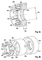
- FIG. 2a 3 shows, schematically illustrated, a longitudinal section of a representation of an arrangement 201 for an electrode line connection bush, which comprises a sleeve 202 with a sleeve wall 203, spring contact elements 230, 231, 232, 233, and a sealing ring 211 with a sealing ring thickness 212.
- the sealing ring 211 has a circular opening 213 for receiving an electrode conduit with a round cross-section and is shaped such that the sleeve wall is sealed against the opening 213.
- the sleeve 202 has an arranged in the sleeve interior partition 204, which divides the sleeve interior along a - not shown in this figure - sleeve longitudinal axis.
- the partition wall 204 has a centrally arranged circular opening for passing through an electrode line plug.
- the diameter of the partition breakthrough corresponds to the diameter of the gasket breakthrough 213.
- the sealing washer 211 has a sealing washer thickness 212 so that the aperture of the sealing washer 211 has a breakthrough inner wall.
- the breakthrough inner wall has two longitudinally arranged in sleeve longitudinal axis sealing lips. The sealing lips each have radially inwardly and are integrally formed on the sealing disc.
- FIG. 2b shows - shown schematically - an exploded view of in FIG. 2a in longitudinal section shown arrangement for an electrode line socket.
- the arrangement for an electrode lead bush comprises a sleeve 202, a sealing washer 211 and a spring-contact element carrier 215 with six molded spring contact elements 230, 231, 232, 233, 234 and 235.
- the sleeve 202 has a sleeve wall 203, which comprises a sleeve interior.
- the sleeve interior is open along the sleeve longitudinal axis 214 to the sleeve ends at least at one end and in the embodiment at both ends (end faces).
- the sleeve 202 has a partition wall 204, which is arranged in the sleeve interior and formed on the sleeve wall 203.
- the partition 204 has a centrally arranged circular opening for the passage of an electrode line plug along the sleeve longitudinal axis 204.
- the partition wall 204 is spaced from the sleeve ends in the direction of the sleeve longitudinal axis 204 in each case.
- the spring-contact element carrier 215 is designed as a circular flat disc, which has a centrally arranged opening for the passage of an electrode line plug.
- the spring contact element carrier 215 has six circumferentially uniformly arranged spring contact elements 230, 231, 232, 233, 234 and 235, which are integrally formed on the outer edge of the spring contact element carrier 215.
- the spring contact elements are each formed from a wavy turned leaf spring, wherein the leaf spring has two turning sections each having opposite Wenderaumssinn and thus has an S-shaped waveform.
- the thus formed spring-contact elements 230, 231, 232, 233, 234 and 235 are formed under deflection along the Federauslenkungsachse form a deflection counteracting spring force and can - in the application - when introducing an electrode line connector resiliently - substantially radially - outward dodge.
- the spring contact element carrier 215 has in the circumferential direction in each case laterally adjacent to the spring contact elements recess areas.
- the spring-contact element carrier also has in the circumferential direction on the inner edge, which adjoins the opening of the spring-contact element carrier, each with respect to each spring contact element arranged recess regions.
- the spring contact element carrier 215 and the spring contact elements are punched from a piece of sheet metal.
- the spring-contact elements are each formed of radially radially outwardly facing leaf spring strips which are bent at right angles to form the waveform on the circumferential extension of the spring-contact element carrier 215 and formed in the further course to an S-shaped waveform.
- the recesses on the side of the spring contact elements are cut so deep in the radial direction that the right angle bent spring contact element does not exceed the outer diameter of the spring-contact element carrier.
- the recesses on the inner edge of the spring-contact element carrier 215 for breakthrough are cut so deep outward in the radial direction that a still standing portion of the spring-contact element carrier 215 between the outer and the inner recesses - seen in the radial direction - forms a torsion spring acting in the tangential direction.
- the torsion spring thus formed supports the spring action of the spring contact element such that the torsion spring acts in series with the spring contact element.
- the resulting total spring stiffness, formed from the spring stiffness of the torsion spring and the spring stiffness of the spring contact element, is smaller than the spring stiffness of the spring contact element without the series-acting torsion spring.
- the spring-contact element carrier 215 is dimensioned in its outer peripheral diameter such that it can be inserted along the sleeve longitudinal axis in the sleeve interior.
- the arrangement also includes a - in FIG. 2a already described sealing washer 211, which has a ring groove spaced from the outer sealing disc edge. The diameter of the ring groove corresponds to the diameter of the sleeve 202, so that one end of the sleeve wall 203 can be inserted in the direction of the sleeve longitudinal axis in the annular groove of the sealing washer 212.
- FIGS. 3a and 3b differs from the previously described by the design of the spring contact elements. These each have only one turning section and are C-shaped.
Landscapes
- Health & Medical Sciences (AREA)
- Engineering & Computer Science (AREA)
- Biomedical Technology (AREA)
- Nuclear Medicine, Radiotherapy & Molecular Imaging (AREA)
- Radiology & Medical Imaging (AREA)
- Life Sciences & Earth Sciences (AREA)
- Animal Behavior & Ethology (AREA)
- General Health & Medical Sciences (AREA)
- Public Health (AREA)
- Veterinary Medicine (AREA)
- Electrotherapy Devices (AREA)
- Coupling Device And Connection With Printed Circuit (AREA)
- Details Of Connecting Devices For Male And Female Coupling (AREA)
- Measuring Leads Or Probes (AREA)
Applications Claiming Priority (2)
| Application Number | Priority Date | Filing Date | Title |
|---|---|---|---|
| DE102004017659A DE102004017659A1 (de) | 2004-04-05 | 2004-04-05 | Federkontaktelement |
| EP05102602A EP1584350B1 (fr) | 2004-04-05 | 2005-04-01 | Elément de contact de ressort |
Related Parent Applications (1)
| Application Number | Title | Priority Date | Filing Date |
|---|---|---|---|
| EP05102602A Division EP1584350B1 (fr) | 2004-04-05 | 2005-04-01 | Elément de contact de ressort |
Publications (1)
| Publication Number | Publication Date |
|---|---|
| EP1952840A1 true EP1952840A1 (fr) | 2008-08-06 |
Family
ID=34895557
Family Applications (2)
| Application Number | Title | Priority Date | Filing Date |
|---|---|---|---|
| EP08008087A Ceased EP1952840A1 (fr) | 2004-04-05 | 2005-04-01 | Agencement de contact |
| EP05102602A Not-in-force EP1584350B1 (fr) | 2004-04-05 | 2005-04-01 | Elément de contact de ressort |
Family Applications After (1)
| Application Number | Title | Priority Date | Filing Date |
|---|---|---|---|
| EP05102602A Not-in-force EP1584350B1 (fr) | 2004-04-05 | 2005-04-01 | Elément de contact de ressort |
Country Status (4)
| Country | Link |
|---|---|
| US (1) | US7587244B2 (fr) |
| EP (2) | EP1952840A1 (fr) |
| AT (1) | ATE539798T1 (fr) |
| DE (1) | DE102004017659A1 (fr) |
Families Citing this family (41)
| Publication number | Priority date | Publication date | Assignee | Title |
|---|---|---|---|---|
| DE102005042369A1 (de) * | 2005-09-07 | 2007-03-15 | Biotronik Crm Patent Ag | Einschraubelektrodensonde zur kardiologischen Anwendung |
| DE102006053729A1 (de) | 2006-11-15 | 2008-05-21 | Biotronik Crm Patent Ag | Kontaktanordnung, Kontaktbaugruppe, implantierbare Vorrichtung und Elektrodenleitung |
| DE102007039554B4 (de) * | 2007-08-22 | 2010-07-29 | Osypka, Peter, Dr.- Ing. | Herzschrittmacher-Elektrode mit Schraubwendel und Zuleitungswendel |
| US9095728B2 (en) | 2008-09-05 | 2015-08-04 | Medtronic, Inc. | Electrical contact for implantable medical device |
| US8062063B2 (en) | 2008-09-30 | 2011-11-22 | Belden Inc. | Cable connector having a biasing element |
| DE102009001573B3 (de) * | 2009-03-16 | 2010-08-05 | Tyco Electronics Amp Gmbh | Elektrisch leitendes Federelement, Kontaktelement und Steckverbinder |
| JP2013515224A (ja) * | 2009-12-29 | 2013-05-02 | サン−ゴバン パフォーマンス プラスティックス コーポレイション | ばねおよびその製造方法 |
| US8731670B2 (en) * | 2010-04-27 | 2014-05-20 | Oscor Inc. | Passive electrical connector |
| WO2011139632A2 (fr) * | 2010-04-29 | 2011-11-10 | Donatelle Plastics, Inc. | Embase pour générateur d'impulsions implantable et procédé de fabrication de celui-ci |
| NL2005480C2 (nl) | 2010-10-07 | 2012-04-11 | Meco Equip Eng | Inrichting voor het eenzijdig elektrolytisch behandelen van een vlak substraat. |
| US20120089203A1 (en) * | 2010-10-12 | 2012-04-12 | Advanced Neuromodulation Systems, Inc. | Electrical connections for use in implantable medical devices |
| BR112013010925B1 (pt) | 2010-11-01 | 2021-03-23 | Ppc Broadband, Inc. | Conector elétrico com membro de aterramento |
| US8376769B2 (en) | 2010-11-18 | 2013-02-19 | Holland Electronics, Llc | Coaxial connector with enhanced shielding |
| US9252499B2 (en) | 2010-12-23 | 2016-02-02 | Mediatek Inc. | Antenna unit |
| DE102011101856A1 (de) * | 2011-01-21 | 2012-07-26 | Abb Technology Ag | Kontaktsystem für Stromleiter |
| US8157588B1 (en) | 2011-02-08 | 2012-04-17 | Belden Inc. | Cable connector with biasing element |
| US8428724B2 (en) * | 2011-03-11 | 2013-04-23 | Greatbatch Ltd. | Low insertion force electrical connector for implantable medical devices |
| US8369951B2 (en) | 2011-03-29 | 2013-02-05 | Greatbatch Ltd. | Feed-through connector assembly for implantable pulse generator and method of use |
| US9931513B2 (en) | 2011-03-29 | 2018-04-03 | Nuvectra Corporation | Feed-through connector assembly for implantable pulse generator and method of use |
| US8738141B2 (en) | 2011-04-07 | 2014-05-27 | Greatbatch, Ltd. | Contact assembly for implantable pulse generator and method of use |
| US8579652B2 (en) * | 2011-06-16 | 2013-11-12 | Leoni Studer Ag | Fastening device for an electric cable |
| WO2013090201A1 (fr) * | 2011-12-12 | 2013-06-20 | Michael Holland | Connecteur à continuité de signal |
| JP5873933B2 (ja) | 2011-12-28 | 2016-03-01 | カーディアック ペースメイカーズ, インコーポレイテッド | スイッチバックパターンを含む環状圧縮性要素 |
| US9138586B2 (en) | 2012-01-27 | 2015-09-22 | Greatbatch Ltd. | Contact block using spherical electrical contacts for electrically contacting implantable leads |
| US9662506B2 (en) * | 2013-07-18 | 2017-05-30 | Boston Scientific Neuromodulation Corporation | Systems and methods for making and using improved operating-room cables for electrical stimulation systems |
| US9362666B2 (en) * | 2014-09-12 | 2016-06-07 | Cooper Technologies Company | Anti-decoupling spring |
| US9278224B1 (en) | 2014-11-03 | 2016-03-08 | Donatelle Plastics, Inc. | Electrical connector ring for implantable medical device |
| EP3187224B1 (fr) | 2016-01-04 | 2021-06-02 | Donatelle Plastics, Inc. | Anneau de connecteur électrique pour dispositif médical implantable |
| US10199766B2 (en) * | 2016-04-22 | 2019-02-05 | Westinghouse Air Brake Technologies Corporation | Breakaway railcar power connector |
| USD833978S1 (en) | 2016-04-22 | 2018-11-20 | Westinghouse Air Brake Technologies Corporation | Rail car power connector |
| US9666973B1 (en) * | 2016-06-10 | 2017-05-30 | Amphenol Corporation | Self-locking connector coupling |
| DE102017110696A1 (de) | 2017-05-17 | 2018-11-22 | Hanon Systems | Stromschiene und Verfahren zur Kontaktierung eines elektrischen Motors |
| US11139603B2 (en) | 2017-10-03 | 2021-10-05 | Boston Scientific Neuromodulation Corporation | Connectors with spring contacts for electrical stimulation systems and methods of making and using same |
| DE102017218133A1 (de) * | 2017-10-11 | 2019-04-11 | Bayerische Motoren Werke Aktiengesellschaft | Schirmübergabe für eine Steckverbindung |
| DE102017124775A1 (de) * | 2017-10-24 | 2019-04-25 | Karl Storz Se & Co. Kg | Handhabungseinrichtung für ein mikroinvasives medizinisches Instrument |
| US11545796B2 (en) * | 2018-04-25 | 2023-01-03 | Ppc Broadband, Inc. | Coaxial cable connectors having port grounding |
| DE102020200976A1 (de) | 2020-01-28 | 2021-07-29 | Te Connectivity Germany Gmbh | Abschirmfederhülse für Hochstromsteckverbindungen |
| DE102020210534B4 (de) * | 2020-04-30 | 2023-03-23 | Te Connectivity Germany Gmbh | Kontaktsystem |
| DE102021102864B3 (de) * | 2021-02-08 | 2022-01-20 | Heraeus Deutschland GmbH & Co. KG | Federkontaktring |
| US20220331580A1 (en) * | 2021-04-15 | 2022-10-20 | Tc1 Llc | Systems and methods for medical device connectors |
| TWI819791B (zh) * | 2022-09-13 | 2023-10-21 | 晝思有限公司 | 探針頭、探針組件及所組成的彈簧式探針結構 |
Citations (7)
| Publication number | Priority date | Publication date | Assignee | Title |
|---|---|---|---|---|
| US5275620A (en) | 1990-05-21 | 1994-01-04 | Telectronics, N.V. | Implantable lead connectors and remote lead assembly |
| EP0590756A2 (fr) | 1992-09-30 | 1994-04-06 | Telectronics N.V. | Connecteur autobloquant pour conducteur de stimulateur implantable |
| DE19609367A1 (de) | 1996-03-04 | 1997-09-11 | Biotronik Mess & Therapieg | Herzschrittmacher |
| US5730628A (en) * | 1996-09-25 | 1998-03-24 | Pacesetter, Inc. | Multi-contact connector for an implantable medical device |
| EP0840400A2 (fr) | 1996-11-05 | 1998-05-06 | Vlt Corporation | Contact à douille |
| EP0848584A1 (fr) * | 1996-12-13 | 1998-06-17 | Molex Incorporated | Dispositif tridimensionnel de connexion électrique |
| US20040167582A1 (en) * | 2003-02-25 | 2004-08-26 | Cardiac Pacemakers, Inc. | Ring connector for implantable medical devices |
Family Cites Families (7)
| Publication number | Priority date | Publication date | Assignee | Title |
|---|---|---|---|---|
| US3678445A (en) * | 1970-07-31 | 1972-07-18 | Itt | Electrical connector shield |
| CA1070792A (fr) * | 1976-07-26 | 1980-01-29 | Earl A. Cooper | Connecteur electrique, dispositif antiparasite et methode de fabrication |
| US4426127A (en) * | 1981-11-23 | 1984-01-17 | Omni Spectra, Inc. | Coaxial connector assembly |
| US4423919A (en) * | 1982-04-05 | 1984-01-03 | The Bendix Corporation | Electrical connector |
| US6332815B1 (en) * | 1999-12-10 | 2001-12-25 | Litton Systems, Inc. | Clip ring for an electrical connector |
| US7164951B2 (en) * | 2003-07-31 | 2007-01-16 | Medtronic, Inc. | Electrical connector assembly having integrated conductive element and elastomeric seal for coupling medical leads to implantable medical devices |
| US20050107859A1 (en) * | 2003-11-14 | 2005-05-19 | Terry Daglow | System and method of establishing an electrical connection between an implanted lead and an electrical contact |
-
2004
- 2004-04-05 DE DE102004017659A patent/DE102004017659A1/de not_active Withdrawn
-
2005
- 2005-04-01 EP EP08008087A patent/EP1952840A1/fr not_active Ceased
- 2005-04-01 EP EP05102602A patent/EP1584350B1/fr not_active Not-in-force
- 2005-04-01 AT AT05102602T patent/ATE539798T1/de active
- 2005-04-05 US US11/099,064 patent/US7587244B2/en not_active Expired - Fee Related
Patent Citations (7)
| Publication number | Priority date | Publication date | Assignee | Title |
|---|---|---|---|---|
| US5275620A (en) | 1990-05-21 | 1994-01-04 | Telectronics, N.V. | Implantable lead connectors and remote lead assembly |
| EP0590756A2 (fr) | 1992-09-30 | 1994-04-06 | Telectronics N.V. | Connecteur autobloquant pour conducteur de stimulateur implantable |
| DE19609367A1 (de) | 1996-03-04 | 1997-09-11 | Biotronik Mess & Therapieg | Herzschrittmacher |
| US5730628A (en) * | 1996-09-25 | 1998-03-24 | Pacesetter, Inc. | Multi-contact connector for an implantable medical device |
| EP0840400A2 (fr) | 1996-11-05 | 1998-05-06 | Vlt Corporation | Contact à douille |
| EP0848584A1 (fr) * | 1996-12-13 | 1998-06-17 | Molex Incorporated | Dispositif tridimensionnel de connexion électrique |
| US20040167582A1 (en) * | 2003-02-25 | 2004-08-26 | Cardiac Pacemakers, Inc. | Ring connector for implantable medical devices |
Also Published As
| Publication number | Publication date |
|---|---|
| ATE539798T1 (de) | 2012-01-15 |
| DE102004017659A1 (de) | 2005-10-27 |
| US20060004419A1 (en) | 2006-01-05 |
| US7587244B2 (en) | 2009-09-08 |
| EP1584350A3 (fr) | 2005-12-28 |
| EP1584350B1 (fr) | 2012-01-04 |
| EP1584350A2 (fr) | 2005-10-12 |
Similar Documents
| Publication | Publication Date | Title |
|---|---|---|
| EP1584350B1 (fr) | Elément de contact de ressort | |
| EP0598261B1 (fr) | Presse-etoupe pour câble de mise à la masse ou de blindage | |
| EP1275173B1 (fr) | Connecteur comportant une douille | |
| EP0803953B1 (fr) | Presse-étoupe pour câble | |
| DE69815744T2 (de) | Rotierende Erdungskupplung zum äusseren Erden von Gehäusen | |
| EP0308784B1 (fr) | Bride de serrage pour la fixation de roulements à contact lisse articulés | |
| DE102009030463A1 (de) | Elektrischer Steckverbinder | |
| DE1615718B1 (de) | Kontaktbuchse fuer elektrische Buchsen-Stift-Steckverbindungen | |
| DE19804625C2 (de) | Gummipfropfen für wasserdichte Verbinder | |
| DE102012105258A1 (de) | Schirmhülse und Abschirmendelement umfassend eine Schirmhülse | |
| EP1459411B1 (fr) | Connecteur monte sur un cable | |
| WO2007019918A1 (fr) | Connecteur comprenant un ressort de retenue destine a une borne de mise a la terre | |
| DE3912189C2 (fr) | ||
| EP3574559B1 (fr) | Passage de câbles doté de propriétés de blindage et d'étanchéité | |
| DE4316903C2 (de) | Kontaktierungsvorrichtung für den Metallgeflechtmantel geschirmter Leitungen | |
| EP2104188B1 (fr) | Joint haute fréquence de raccords enfichables haute fréquence | |
| DE102018105770B4 (de) | Steckverbinder mit einer Verbindungsanordnung für einen Schutzleiterkontakt | |
| DE102004002403B3 (de) | Federelement, insbesondere für eine Kontaktbuchse | |
| EP0342385B1 (fr) | Lamelle de blindage | |
| EP2262071B1 (fr) | Traversée de câble | |
| DE102004007357B4 (de) | HF-Steckkontakt mit einer Crimphülse und Crimphülse für einen HF-Steckkontakt | |
| DE4037712C2 (de) | Fahrzeugantenne | |
| DE4031167C2 (de) | Elektrische Leuchte | |
| DE10339958B4 (de) | Elektrischer Steckkontakt | |
| DE202004007160U1 (de) | Vorrichtung zum Befestigen einer Antenne auf einem Fahrzeug |
Legal Events
| Date | Code | Title | Description |
|---|---|---|---|
| PUAI | Public reference made under article 153(3) epc to a published international application that has entered the european phase |
Free format text: ORIGINAL CODE: 0009012 |
|
| AC | Divisional application: reference to earlier application |
Ref document number: 1584350 Country of ref document: EP Kind code of ref document: P |
|
| AK | Designated contracting states |
Kind code of ref document: A1 Designated state(s): AT BE BG CH CY CZ DE DK EE ES FI FR GB GR HU IE IS IT LI LT LU MC NL PL PT RO SE SI SK TR |
|
| 17P | Request for examination filed |
Effective date: 20090112 |
|
| 17Q | First examination report despatched |
Effective date: 20090219 |
|
| AKX | Designation fees paid |
Designated state(s): AT BE BG CH CY CZ DE DK EE ES FI FR GB GR HU IE IS IT LI LT LU MC NL PL PT RO SE SI SK TR |
|
| STAA | Information on the status of an ep patent application or granted ep patent |
Free format text: STATUS: THE APPLICATION HAS BEEN REFUSED |
|
| 18R | Application refused |
Effective date: 20120101 |