EP1952039B1 - Ausrücklagersystem - Google Patents
Ausrücklagersystem Download PDFInfo
- Publication number
- EP1952039B1 EP1952039B1 EP06819239A EP06819239A EP1952039B1 EP 1952039 B1 EP1952039 B1 EP 1952039B1 EP 06819239 A EP06819239 A EP 06819239A EP 06819239 A EP06819239 A EP 06819239A EP 1952039 B1 EP1952039 B1 EP 1952039B1
- Authority
- EP
- European Patent Office
- Prior art keywords
- guide
- release bearing
- sleeve
- tube
- bearing system
- Prior art date
- Legal status (The legal status is an assumption and is not a legal conclusion. Google has not performed a legal analysis and makes no representation as to the accuracy of the status listed.)
- Not-in-force
Links
- 229910052751 metal Inorganic materials 0.000 description 23
- 239000002184 metal Substances 0.000 description 23
- 239000000463 material Substances 0.000 description 5
- 230000008878 coupling Effects 0.000 description 3
- 238000010168 coupling process Methods 0.000 description 3
- 238000005859 coupling reaction Methods 0.000 description 3
- 238000005096 rolling process Methods 0.000 description 3
- CWYNVVGOOAEACU-UHFFFAOYSA-N Fe2+ Chemical compound [Fe+2] CWYNVVGOOAEACU-UHFFFAOYSA-N 0.000 description 2
- 238000004026 adhesive bonding Methods 0.000 description 2
- 239000000956 alloy Substances 0.000 description 2
- 229910045601 alloy Inorganic materials 0.000 description 2
- 230000005540 biological transmission Effects 0.000 description 2
- 230000015572 biosynthetic process Effects 0.000 description 2
- 238000005755 formation reaction Methods 0.000 description 2
- 238000004519 manufacturing process Methods 0.000 description 2
- 238000003825 pressing Methods 0.000 description 2
- 229910000831 Steel Inorganic materials 0.000 description 1
- 238000000576 coating method Methods 0.000 description 1
- 238000010276 construction Methods 0.000 description 1
- 230000001419 dependent effect Effects 0.000 description 1
- 230000007613 environmental effect Effects 0.000 description 1
- -1 ferrous metals Chemical class 0.000 description 1
- 150000002739 metals Chemical class 0.000 description 1
- 238000000034 method Methods 0.000 description 1
- 230000002093 peripheral effect Effects 0.000 description 1
- 238000005476 soldering Methods 0.000 description 1
- 238000005507 spraying Methods 0.000 description 1
- 239000010959 steel Substances 0.000 description 1
- 238000003466 welding Methods 0.000 description 1
Images


Classifications
-
- F—MECHANICAL ENGINEERING; LIGHTING; HEATING; WEAPONS; BLASTING
- F16—ENGINEERING ELEMENTS AND UNITS; GENERAL MEASURES FOR PRODUCING AND MAINTAINING EFFECTIVE FUNCTIONING OF MACHINES OR INSTALLATIONS; THERMAL INSULATION IN GENERAL
- F16D—COUPLINGS FOR TRANSMITTING ROTATION; CLUTCHES; BRAKES
- F16D21/00—Systems comprising a plurality of actuated clutches
-
- F—MECHANICAL ENGINEERING; LIGHTING; HEATING; WEAPONS; BLASTING
- F16—ENGINEERING ELEMENTS AND UNITS; GENERAL MEASURES FOR PRODUCING AND MAINTAINING EFFECTIVE FUNCTIONING OF MACHINES OR INSTALLATIONS; THERMAL INSULATION IN GENERAL
- F16D—COUPLINGS FOR TRANSMITTING ROTATION; CLUTCHES; BRAKES
- F16D23/00—Details of mechanically-actuated clutches not specific for one distinct type
- F16D23/12—Mechanical clutch-actuating mechanisms arranged outside the clutch as such
- F16D23/14—Clutch-actuating sleeves or bearings; Actuating members directly connected to clutch-actuating sleeves or bearings
Definitions
- the invention relates to a release bearing system with at least one release bearing, with at least one guide sleeve and at least one stationary guide tube, wherein the longitudinally displaceable guide sleeve is guided on the guide tube along the longitudinal central axis of the release bearing system and thereby abuts a displaceable by the guide sleeve bearing ring of the release bearing so that the release bearing is axially movable by means of the bearing ring.
- release bearing system is in DE 103 56 236 A1 described in more detail.
- Mechanical clutches and their actuators in modern drive units need as little space as possible to claim for themselves.
- Extremely short axial construction of such couplings is required especially for actuators of parallel shift transmissions.
- the release bearings should only take up as little axial space as possible.
- the guide sleeves are guided in the guide tube / housing with radial clearance to be axially movable. Due to the short axial design and relatively large guide diameter, the guide sleeve tends during disengagement and engagement for tilting and thus jamming in the guide.
- the tilting can be restricted by reducing the radial play. However, this measure can not be achieved in every case and also not sufficiently.
- the possible deviations from the ideal desired dimension caused by production and assembly and, on the other hand, the environmental influences such as temperature and their consequences must be taken into account.
- pairings of plastic with metals are used in such guides.
- the guide sleeve or the guide tube / housing is often made of plastic and the partner, the guide tube or the guide sleeve made of metal, so that when choosing the radial clearance and the different thermal expansion coefficients of the materials and the resulting different thermal expansion are observed. If there are too small clearance fits in the sliding seat, the sliding fit between the guide sleeve and the guide tube is jammed due to different thermal expansions.
- Out DE 197 00 930 A1 is a release device is known, which achieves by means of movement limiting means on the one hand a simple assembly of the device and on the other hand does not affect the mobility of the release device.
- the object of the invention is therefore to improve the management conditions in release bearing systems of the generic type.
- the release bearing system has at least one longitudinal guide.
- the longitudinal guide is between the guide sleeve and the guide tube of at least one longitudinally extending and therefore aligned parallel to the longitudinal central axis guide groove and a radially engaging the guide groove Guide projection formed.
- the guide projection in the guide groove and the guide groove are axially displaceable relative to each other.
- the guide is of the sliding seat, with which the guide sleeve and the guide tube are arranged one inside the other, so far separated that the longitudinal guide is not affected by the radial play in the longitudinal guide.
- the guide of the guide sleeve to the guide tube is, similar to multi-waves, formed by a combination of radially inwardly or outwardly-recessed guide grooves and projections / wedges. These interlocking profiles are arranged outside the actual original guide diameter of the guide sleeve and the guide tube.
- the actual guidance of the guide sleeve to the guide tube is made by the inventive longitudinal guide and not on the original guide diameters.
- a jam-free guidance is achieved by the tangentially narrow running and related to the longitudinal center axis guide.
- Under guide tube are all suitable types of housings or fixed to the housing of the clutch or the vehicle and thus relative to the release bearing axially displaceable tubular receptacles with cylindrical or otherwise shaped cross section to understand that are suitable, in the shape of the guide tube corresponding guide sleeve inside or outside.
- the guide tube or the guide sleeve having the guide projections.
- the guide projections are then selectively directed radially inwards or outwards and engage in correspondingly corresponding guide grooves on the guide sleeve or on the guide tube.
- An embodiment of the invention provides that one or more guide grooves are formed on the guide tube or on the guide sleeve, and that the guide sleeve or the guide tube has one or more guide projections.
- guide groove is open radially inwardly toward the longitudinal center axis of the release bearing system.
- the guide groove is open radially outward.
- the guide projections are selectively directed away from the guide sleeve / guide tube radially inwardly or outwardly, distributed around the circumference and / or axially juxtaposed or offset from one another in the longitudinal direction and engage in correspondingly corresponding guide grooves on the guide tube or on the guide sleeve.
- the guide sleeve is arranged in one case in the guide tube - in other cases, the guide tube is arranged in the guide sleeve.
- a further embodiment of the invention provides that the guide sleeve and the guide tube are arranged concentrically with each other to a sliding seat.
- a radial play is formed between the guide tube and the guide sleeve.
- the radial play is greater than a tangentially directed guide play in the longitudinal guide between the guide and the guide projection.
- the guide tube is guided closer to the guide protrusions in the guide groove than the guide tube at its inner diameter on the shaft or at its outer diameter to the guide tube. Jamming in the sliding seat by tilting or by differential thermal expansion of the mutually displaceable sleeves / tubes is thus prevented
- a further embodiment of the invention provides that the guide projections have parallel aligned guide flanks. Each of these guide flanks is parallel to one of the inner flanks on the guide groove.
- the guide play in the longitudinal guide is formed in the guide groove between the flanks. Between the radially outwardly facing free end of the guide projection and the radially inwardly directed groove bottom of the guide groove, a relatively large radial clearance is formed. The radial clearance is at least so great that different thermal expansion coefficients of the materials of the paired components are taken into account. Unhindered expansion or shrinkage is especially in an arrangement with the aforementioned parallel flanks possible. The tilting and possibly resulting tilting is prevented.
- the sliding behavior of the guide projections can be improved if at least one of the elements of the pairing in sliding contact areas, in particular in the longitudinal guide, is provided with suitable sliding coatings.
- FIG. 1 The outer ring 4 of the release bearing 2 is in contact with a guide sleeve 5.
- the guide sleeve 5 is longitudinally along the longitudinal central axis 6 displaceable in a housing fixed guide tube 7.
- the guide sleeve 5 made of plastic is relative to the Diameters of the release bearing formed long and therefore sufficiently guided in the guide tube 7. The displaceability is ensured by a radial clearance in the sliding seat between the guide tube 7 and the guide sleeve 5.
- the guide sleeve 5 acts on the outer ring 4, that the release bearing 2 is axially displaceable about the actuation path in the coupling not shown axially along the longitudinal central axis 6.
- the disengaging forces for disengaging the clutch are transmitted via the rolling elements 33 to the inner ring 34 and from the end face 35 of the inner ring 34 to the spring plate, not shown, of the clutch.
- the front side of the guide sleeve 5, a support member 31 is formed, via which the outer ring 4 is supported on the plastic part and over which the release bearing 2 is taken axially with the guide sleeve 5.
- the support member is, for example, a ring made of sheet metal with a profile which is crimped hook-shaped viewed in longitudinal section.
- the guide sleeve acts on the inner ring of the release bearing and the disengaging forces on the rolling elements on the outer ring and from there to the spring be transferred to the coupling.
- the release bearing 3 is associated with a guide sleeve 5a.
- the guide sleeve is in this case made of plastic, but may also be made of non-ferrous metal or sheet metal.
- Between the guide tube 7 and the guide sleeve 5a at least three longitudinal guides 32 are formed, one of which in the longitudinal section to FIG. 1 is shown.
- the other longitudinal guides 32 are arranged at other positions of the circumference not detected with the longitudinal section.
- the guide sleeve 5a has longitudinally extending and therefore parallel to the longitudinal central axis 6 aligned guide grooves 8.
- the guide grooves 8 are recessed radially from the inside to the outside.
- the guide tube 7 has radially outwardly projecting guide projections 9. Each guide projection 9 engages in one of the guide grooves 8.
- FIG. 2 is the guide tube 7 made of sheet metal with guide projections 9 which protrude radially as tabs 10.
- the tabs 10 are bent radially outwardly from a corresponding recessed portion of the sheet of the guide tube 7.
- Each of the guide projections 9 engages radially in one of the guide grooves 8. Since the guide projections 9 are aligned along the same with the guide grooves 8, the guide tube 7 with the guide projections 9 in the guide sleeve 5a at least by the actuation path of the release bearing 2 along (in the illustration FIG. 2 perpendicular to the plane of representation).
- FIG. 2a shows the detail Z FIG. 2 in enlarged and not to scale representation.
- the inner edges 13 of the guide grooves 9 are aligned parallel to each other and are tangent to each other tangentially to the imaginary outer peripheral line 14 of the guide sleeve 5a.
- the tangential guide clearance S between the respective inner flanks 13 and the guide flanks 23 on the guide projections 9 is very small and smaller than the radial clearance of the sliding seat between guide sleeve 5a and guide tube 7.
- a tangential and longitudinally aligned planar guide surface 22 is radial either Also, the guide game S formed or the game is much larger than S, so that the elements can freely expand radially at different coefficients of thermal expansion.
- FIG. 3 shows an alternative design of a guide tube 15 at a cutout.
- the guide tube 15 is composed of several parts of the guide tube itself and from longitudinal ribs 11.
- the longitudinal ribs 11 made of plastic are snapped into the guide tube made of sheet metal, pressed or injected.
- the guide tube 15 is outside and / or inside over the flanks 16 and / or 17 and not over the radially outwardly directed, tangentially and longitudinally extending surface 24, for example, in the guide grooves 8 of a guide sleeve 5a.
- FIG. 4 shows a detail of a guide sleeve 18, which is made in two parts from a metal tube 19 and a plastic sleeve 20.
- the plastic sleeve 20 is fixed by overmolding of the metal tube 19 or by pressing or snapping onto the metal tube 19 on the metal tube 19.
- materials for the metal pipe 19 are non-ferrous metals or steel and their alloys are provided.
- the guide sleeve 18 on radially projecting guide projections 9, which engage, for example, in guide grooves 8 of a corresponding guide tube 36.
- the plastic sleeve 20 has the guide projections 9 with the parallel guide flanks 21.
- the guide sleeve 18 is guided over the guide projections 9 in a correspondingly provided with guide grooves guide tube 36.
- FIG. 5 shows a detail of a guide sleeve 25, which is composed as a profile 26 made of metal in conjunction with a sleeve 27 made of plastic.
- the tubular profile 26 is for example a precision drawing part and has radial formations 28, which are formed locally as a single guide projections 9 or as over the entire length extending guide projections 9 from the sheet of the profile 26.
- the profile 26 and the sleeve 27 are joined together by spraying, vulcanizing, gluing, pressing and snapping.
- the guide sleeve 25 is guided over the guide projections 9 outside, for example, in the guide grooves 8 of a guide tube 36. It is also conceivable to use a guide sleeve, which is exclusively formed only by the profile 26 without further sleeve made of plastic.
- FIG. 6 shows a detail of a guide tube 29, in which the guide projections 9 are individually attached as an angular items made of plastic or sheet metal on a hollow cylindrical sleeve made of metal or plastic and secured thereto by gluing, welding, riveting, soldering or the like.
- the guide tube 29 is guided over the guide projections 9 outside, for example, in the guide grooves 8 of a guide sleeve 5a.
- FIG. 7 shows a detail of a guide sleeve 30 which is integrally formed with the guide projections 9 made of plastic or metal, such as non-ferrous metal and their alloys.
- the guide sleeve 30 is guided over the guide projections 9 outside, for example, in the guide grooves 8 of a guide tube 7.
- FIG. 8 shows a detail of a guide sleeve 37 made of plastic.
- the guide sleeve 37 at least one of the guide projections 9 is integrally formed.
- the guide projections 9 protrude radially inwards from the guide sleeve 37 and engage in a guide groove 8 on a guide tube 38 which is solidly formed of plastic or metal.
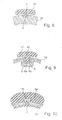
- FIG. 9 shows a detail of a guide tube 39 made of sheet metal.
- the sheet of the guide tube 39 at least one of the guide projections 9 is formed.
- the guide projections 9 project radially inward from the guide tube 39 and engage in a guide groove 8 opening radially outward in a guide sleeve 40.
- the guide sleeve 40 is one piece with the guide groove 8 cold formed from sheet metal.
- the outer guide sleeve is provided in applications in disengagement systems for parallel shift transmissions with a guide projection which engages inwardly into the guide groove 8a.
- FIG. 10 shows a detail of a guide tube 43 made of sheet metal.
- the profile of the guide tube 43 has radially outwardly facing guide projections 9a.
- the guide projections engage in the guide grooves 8b.
- the inner guide sleeve has outwardly facing guide projections 9b, which engage in the inner contour of the guide projections 9a.
Landscapes
- Engineering & Computer Science (AREA)
- General Engineering & Computer Science (AREA)
- Mechanical Engineering (AREA)
- Mechanical Operated Clutches (AREA)
Description
- Die Erfindung betrifft ein Ausrücklagersystem mit wenigstens einem Ausrücklager, mit zumindest einer Führungshülse und mit mindestens einem ortsfesten Führungsrohr, wobei die längsverschiebbare Führungshülse an dem Führungsrohr entlang der Längsmittelachse des Ausrücklagersystems geführt ist und dabei an einem durch die Führungshülse verschiebbaren Lagerring des Ausrücklagers so anliegt, dass das Ausrücklager mittels des Lagerringes axial beweglich ist.
- Eine derartiges Ausrücklagersystem ist in
DE 103 56 236 A1 näher beschrieben. Mechanische Schaltkupplungen und deren Betätigungseinrichtungen in modernen Antriebseinheiten müssen so wenig wie möglich Bauraum für sich beanspruchen. Extrem axial kurze Bauweise von derartigen Kupplungen ist insbesondere bei Betätigungseinrichtungen von Parallelschaltgetrieben gefordert. Demzufolge dürfen auch die Ausrücklager nur so wenig wie möglich axial Bauraum für sich beanspruchen. Die Führungshülsen sind in dem Führungsrohr/Gehäuse mit Radialspiel geführt um axial beweglich zu sein. Aufgrund der kurzen axialen Bauweise und relativ großer Führungsdurchmesser neigt die Führungshülse bei Aus- und Einrücken zum Verkippen und somit zum Verklemmen in der Führung. - Das Verkippen kann durch Verringerung des Radialspiels eingeschränkt werden. Diese Maßnahme lässt sich jedoch nicht in jedem Fall und auch nicht in ausreichendem Maße verwirklichten. Im Radialspiel sind einerseits die möglichen durch Fertigung und Montage bedingten Maßabweichungen vom idealen sollmaß und andererseits die Umgebungseinflüsse wie Temperatur und deren Folgen zu berücksichtigen. Häufig werden in derartigen Führungen Paarungen aus Kunststoff mit Metallen eingesetzt. So ist die Führungshülse oder das Führungsrohr/Gehäuse oft aus Kunststoff und der Partner, das Führungsrohr oder die Führungshülse aus Metall, so dass bei der Wahl des Radialspiels auch die unterschiedlichen Wärmedehnungskoeffizienten der Werkstoffe und die daraus resultierenden unterschiedlichen Wärmedehnungen zu beachten sind. Bei zu kleinen Spielpassungen im Schiebesitz klemmt derSchiebesitz zwischen Führungshülse und Führungsrohr aufgrund unterschiedlichen Wärmedehnungen.
- Aus
DE 197 00 930 A1 ist eine Ausrückvorrichtung bekannt, die mittels Bewegungsbegrenzungsmitteln einerseits eine leichte Montage der Vorrichtung erzielt und andererseits die Beweglichkeit der Ausrückvorrichtung nicht beeinträchtigt. Dazu wird vorgeschlagen eine axiale Fixierung des Führungsrohres im Lagerträger im Sinne eines Bajonettverschlusses oder einer Rastvorrichtung umzusetzen. - Die Aufgabe der Erfindung ist es daher, die Führungsverhältnisse in Ausrücklagersystemen der gattungsbildenden Art zu verbessern.
- Diese Aufgabe ist nach dem Gegenstand des Anspruches 1 und weiterer abhängiger Ansprüche gelöst.
- Das Ausrücklagersystem weist wenigstens eine Längsführung auf. Die Längsführung ist zwischen der Führungshülse und dem Führungsrohr aus zumindest einer längs gerichtet verlaufenden und deshalb zu der Längsmittelachse parallel ausgerichteten Führungsnut und aus einem radial die Führungsnut eingreifenden Führungsvorsprung gebildet. Der Führungsvorsprung in der Führungsnut und die Führungsnut sind relativ zueinander axial verschiebbar. Die Führung ist von dem Verschiebesitz, mit dem die Führungshülse und das Führungsrohr ineinander angeordnet sind, soweit getrennt, dass die Längsführung von den Radialspielen in der Längsführung nicht beeinflusst ist.
- Die Führung der Führungshülse zum Führungsrohr ist, ähnlich wie bei Vielwellen, über eine Kombination von radial nach innen oder nach außen gerichtet-vertieften Führungsnuten und Vorsprüngen/Keilen gebildet. Diese ineinander greifenden Profile sind außerhalb der eigentlichen ursprünglichen Führungsdurchmesser der Führungshülse und des Führungsrohrs angeordnet. Die eigentliche Führung der Führungshülse zum Führungsrohr wird durch die erfindungsgemäße Längsführung und nicht mehr an den ursprünglichen Führungsdurchmessern vorgenommen. Eine klemmfreie Führung ist durch die tangential schmal ausgeführte und auf die Längsmittelachse bezogene Führung erreicht.
- Unter Führungsrohr sind alle geeigneten Arten von Gehäusen oder zum Gehäuse der Kupplung oder des Fahrzeugs ortsfesten und somit relativ zum Ausrücklager nicht axial verschiebbaren rohrförmigen Aufnahmen mit zylindrischem oder anders gestaltetem Querschnitt zu verstehen, die geeigneten sind, die in der Gestalt mit dem Führungsrohr korrespondierende Führungshülse innen oder außen aufzunehmen. Dabei kann das Führungsrohr oder die Führungshülse die Führungsvorsprünge aufweisen. Die Führungsvorsprünge sind dann wahlweise radial nach innen oder nach außen gerichtet und greifen in entsprechend korrespondierende Führungsnuten an der Führungshülse oder an dem Führungsrohr ein.
- Eine Ausgestaltung der Erfindung sieht vor, dass eine oder mehrere Führungsnuten an dem Führungsrohr oder an der Führungshülse ausgebildet sind, und dass die Führungshülse oder das Führungsrohr einen oder mehrere Führungsvorsprünge aufweist. Wenn die Führungsvorsprünge radial nach außen gerichtet sind ist Führungsnut radial nach innen zur Längsmittelachse des Ausrücklagersystems hin offen. Wenn die Führungsvorsprünge radial nach innen gerichtet sind ist die Führungsnut radial nach außen hin offen.
- Die Führungsvorsprünge sind wahlweise von der Führungshülse/Führungsrohr weg radial nach innen oder nach außen gerichtet, am Umfang verteilt und/oder in Längsrichtung axial nebeneinander oder versetzt zueinander angeordnet und greifen in entsprechend korrespondierende Führungsnuten an dem Führungsrohr bzw. an der Führungshülse ein.
- Die Führungshülse ist in einem Fall in dem Führungsrohr angeordnet - in anderen Fällen ist das Führungsrohr in der Führungshülse angeordnet..
- Weitere Ausgestaltungen der Erfindung sehen vor, dass die Führungshülse oder das Führungsrohr und der Führungsvorsprung einteilig miteinander ausgebildet sind oder dass die Führungsvorsprünge an der Führungshülse oder dem Führungsrohr befestigt sind. So ergeben sich vielfältige und kostengünstige Möglichkeiten hinsichtlich der Wahl des Materials und der Paarung von Material, Hinsichtlich der Herstellungsmethoden und der Methoden zur Montage.
- Eine weitere Ausgestaltung der Erfindung sieht vor, dass die Führungshülse und das Führungsrohr konzentrisch ineinander zu einem Schiebesitz angeordnet sind. Dabei ist zwischen dem Führungsrohr und der Führungshülse ein Radialspiel ausgebildet. Das Radialspiel ist größer als ein tangential gerichtetes Führungsspiel in der Längsführung zwischen der Führungsnut und dem Führungsvorsprung. Das Führungsrohr ist an den Führungsvorsprüngen enger in der Führungsnut geführt, als das Führungsrohr an seinem Innendurchmesser auf der Welle oder an seinem Außendurchmesser zu dem Führungsrohr. Ein Verklemmen im Schiebesitz durch Verkippen oder durch unterschiedliche Wärmedehnung der gegeneinander verschiebbaren Hülsen/Rohre ist somit verhindert
- Eine weitere Ausgestaltung der Erfindung sieht vor, dass die Führungsvorsprünge parallel zueinander ausgerichtete Führungsflanken aufweisen. Jede dieser Führungsflanken liegt einer der Innenflanken an der Führungsnut parallel gegenüber. Das Führungsspiel in der Längsführung ist in der Führungsnut zwischen den Flanken ausgebildet. Zwischen dem radial nach außen gewandten freien Ende des Führungsvorsprungs und dem radial nach innen gerichteten Nutgrund der Führungsnut ist ein relativ großes Radialspiel ausgebildet. Das Radialspiel ist mindestens so groß, dass unterschiedliche Wärmeausdehnungskoeffizienten der Werkstoffe der miteinander gepaarten Bauelemente berücksichtigt sind. Ein ungehindertes Ausdehnen bzw. Schrumpfen ist insbesondere in einer Anordnung mit den zuvor erwähnten parallelen Flanken möglich. Das Verkippen und eventuell daraus entstehendes Verkippen ist verhindert.
- Das Gleitverhalten der Führungsvorsprünge kann verbessert werden, wenn mindestens eines der Elemente der Paarung in Gleitkontaktbereichen, insbesondere in der Längsführung, mit geeigneten Gleitbeschichtungen versehen ist.
- Die Erfindung wird nachfolgend anhand von Ausführungsbeispielen näher erläutert.
-
Figur 1 zeigt ein Ausrücklagersystem 1 mit zwei Ausrücklagern 2 und 3. Der Außenring 4 des Ausrücklagers 2 ist im Kontakt mit einer Führungshülse 5. Die Führungshülse 5 sitzt längs entlang der Längsmittelachse 6 verschiebbar in einem gehäusefesten Führungsrohr 7. Die Führungshülse 5 aus Kunststoff ist relativ zu dem Durchmessern des Ausrücklagers lang ausgebildet und deshalb ausreichend in dem Führungsrohr 7 geführt. Die Verschiebbarkeit ist durch ein Radialspiel in dem Schiebesitz zwischen Führungsrohr 7 und der Führungshülse 5 gewährleistet. - Die Führungshülse 5 wirkt so auf den Außenring 4, dass das Ausrücklager 2 um den Betätigungsweg in der nicht weiter dargestellten Kupplung axial entlang der Längsmittelachse 6 verschiebbar ist. Die Ausrückkräfte zum Ausrücken der Kupplung werden über die Wälzkörper 33 auf den Innenring 34 und von der Stirnseite 35 des Innenrings 34 auf die nicht dargestellte Federteller der Kupplung übertragen. Stirnseitig der Führungshülse 5 ist ein Stützelement 31 ausgebildet, über das sich der Außenring 4 an dem Kunststoffteil abstützt und über welches das Ausrücklager 2 axial mit der Führungshülse 5 mitgenommen wird. Das Stützelement ist zum Beispiel ein Ring aus Blech mit einem Profil, das im Längsschnitt betrachtet hakenförmig gebördelt ist. Es gibt auch Anordnungen, bei denen die Führungshülse auf den Innenring des Ausrücklagers wirkt und die Ausrückkräfte über die Wälzkörper auf den Außenring und von dort auf die Feder der Kupplung übertragen werden.
- Dem Ausrücklager 3 ist eine Führungshülse 5a zugeordnet. Die Führungshülse ist in diesem Fall aus Kunststoff, kann aber auch aus Nichteisenmetall oder Blech sein. Zwischen dem Führungsrohr 7 und der Führungshülse 5a sind mindestens drei Längsführungen 32 ausgebildet, von denen eine in dem Längsschnitt nach
Figur 1 dargestellt ist. Die anderen Längsführungen 32 sind an anderen nicht mit dem Längsschnitt erfassten Positionen des Umfangs angeordnet. AusFigur 1 undFigur 2 ist ersichtlich, dass die Führungshülse 5a längs gerichtet verlaufende und deshalb zu der Längsmittelachse 6 parallel ausgerichtete Führungsnuten 8 aufweist. Die Führungsnuten 8 sind radial von innen nach außen vertieft. Die Führungsrohr 7 weist radial nach außen abstehende Führungsvorsprünge 9 auf. Jeder Führungsvorsprung 9 greift in eine der Führungsnuten 8 ein. - In dem Beispiel nach
Figur 2 ist das Führungsrohr 7 aus Blech mit Führungsvorsprüngen 9, die als Laschen 10 radial hervorstehen. Die Laschen 10 sind aus einem entsprechend ausgesparten Abschnitt des Bleches des Führungsrohrs 7 radial nach außen gebogen. Jeder der Führungsvorsprünge 9 greift radial in eine der Führungsnuten 8 ein. Da die Führungsvorsprünge 9 längs gleich mit den Führungsnuten 8 ausgerichtet sind, ist das Führungsrohr 7 mit den Führungsvorsprüngen 9 in der Führungshülse 5a mindestens um den Betätigungsweg des Ausrücklagers 2 längs (in der Darstellung nachFigur 2 senkrecht zur Darstellungsebene) verschiebbar. -
Figur 2a zeigt das Detail Z ausFigur 2 in vergrößerter und nicht maßstäblich Darstellung. Die Innenflanken 13 der Führungsnuten 9 sind parallel zueinander ausgerichtet und liegen einander tangential zur gedachten Außenumfangslinie 14 der Führungshülse 5a gegenüber. Das tangentiale Führungsspiel S zwischen den jeweiligen Innenflanken 13 und den Führungsflanken 23 an den Führungsvorsprüngen 9 ist sehr gering und kleiner als das Radialspiel des Schiebesitzes zwischen Führungshülse 5a und Führungsrohr 7. Zwischen einer tangential und längs ausgerichteten ebenen Führungsfläche 22 ist radial entweder ebenfalls das Führungsspiel S ausgebildet oder das Spiel ist wesentlich größer als S, so dass sich die Elemente bei unterschiedlichen Wärmeausdehnungskoeffizienten ungehindert radial ausdehnen können. - Es ist auch denkbar, dass derartige Führungsflanken 23 oder Führungsflächen 22 in den nach
Figur 2 und der folgenden Figuren betrachteten Querschnitten innen ballig oder außen ballig ausgebildet sind oder ebenflächig aber geneigt zueinander sind. -
Figur 3 zeigt eine alternative Gestaltung eines Führungsrohrs 15 an einem Ausschnitt. Das Führungsrohr 15 ist mehrteilig aus dem Führungsrohr an sich und aus Längsrippen 11 zusammengesetzt. Die Längsrippen 11 aus Kunststoff sind in das Führungsrohr aus Blech eingeschnappt, eingepresst oder eingespritzt. Das Führungsrohr 15 ist außen- oder/und innen über die Flanken 16 oder/und 17 und nicht über die radial nach außen gerichtete, sich tangential und sich längs erstreckende Fläche 24 beispielsweise in den Führungsnuten 8 einer Führungshülse 5a geführt. -
Figur 4 zeigt ein Detail einer Führungshülse 18, die zweiteilig aus einem Metallrohr 19 und aus einer Kunststoffhülse 20 hergestellt ist. Die Kunststoffhülse 20 ist durch Umspritzen des Metallrohres 19 oder durch Aufpressen bzw. Aufschnappen auf das Metallrohr 19 auf dem Metallrohr 19 befestigt. Als Werkstoffe für das Metallrohr 19 sind Nichteisenmetalle oder Stahl und deren Legierungen vorgesehen. In diesem Fall weist die Führungshülse 18 radial hervorstehende Führungsvorsprünge 9 auf, die beispielsweise in Führungsnuten 8 eines entsprechendes Führungsrohrs 36 eingreifen. Die Kunststoffhülse 20 weist die Führungsvorsprünge 9 mit den parallelen Führungsflanken 21 auf. Die Führungshülse 18 ist über die Führungsvorsprünge 9 in einem entsprechend mit Führungsnuten versehenen Führungsrohr 36 geführt. -
Figur 5 zeigt ein Detail einer Führungshülse 25, die als ein Profil 26 aus Metall im Verbund mit einer Hülse 27 aus Kunststoff zusammengesetzt ist. Das rohrförmige Profil 26 ist beispielsweise ein Präzisionsziehteil und weist radiale Ausformungen 28 auf, die örtlich als einzelne Führungsvorsprünge 9 oder als sich über die gesamte Länge erstreckende Führungsvorsprünge 9 aus dem Blech des Profils 26 geformt sind. Das Profil 26 und die Hülse 27 sind durch Spritzen, Vulkanisieren, Kleben, Aufpressen und Einschnappen miteinander verbunden. Die Führungshülse 25 ist über die Führungsvorsprünge 9 außen beispielsweise in den Führungsnuten 8 eines Führungsrohrs 36 geführt. Es ist auch denkbar eine Führungshülse einzusetzen, die ausschließlich nur durch das Profil 26 ohne weiter Hülse aus Kunststoff gebildet ist. -
Figur 6 zeigt ein Detail eines Führungsrohrs 29, bei dem die Führungsvorsprünge 9 einzeln als winkelförmige Einzelteile aus Kunststoff oder aus Blech auf einer hohlzylindrischen Hülse aus Metall oder aus Kunststoff aufgesetzt und auf dieser durch Kleben, Schweißen, Nieten, Löten oder ähnliches befestigt sind. Das Führungsrohr 29 ist über die Führungsvorsprünge 9 außen beispielsweise in den Führungsnuten 8 einer Führungshülse 5a geführt. -
Figur 7 zeigt ein Detail einer Führungshülse 30 die einteilig mit den Führungsvorsprüngen 9 aus Kunststoff oder aus Metall, wie Nichteisenmetall und deren Legierungen, geformt ist. Die Führungshülse 30 ist über die Führungsvorsprünge 9 außen beispielsweise in den Führungsnuten 8 eines Führungsrohrs 7 geführt. -
Figur 8 zeigt ein Detail einer Führungshülse 37 aus Kunststoff. Mit der Führungshülse 37 ist wenigstens einer der Führungsvorsprünge 9 einteilig ausgebildet. Die Führungsvorsprünge 9 stehen von der Führungshülse 37 aus radial nach innen hervor und greifen in eine Führungsnut 8 an einem massiv aus Kunststoff oder Metall gebildeten Führungsrohr 38 ein. -
Figur 9 zeigt ein Detail eines Führungsrohrs 39 aus Blech. In das Blech des Führungsrohrs 39 ist wenigstens einer der Führungsvorsprünge 9 eingeformt. Die Führungsvorsprünge 9 stehen von dem Führungsrohr 39radial nach innen ab und greifen in eine radial nach außen öffnende Führungsnut 8 in einer Führungshülse 40 ein. Die Führungshülse 40 ist einteilig mit der Führungsnut 8 kalt aus Blech geformt. - Die äußere Führungshülse ist bei Anwendungen in Ausrücksystemen für Parallelschaltgetrieben mit einem Führungsvorsprung versehen, welcher nach innen gerichtet in die Führungsnut 8a eingreift.
-
Figur 10 zeigt ein Detail eines Führungsrohrs 43 aus Blech. Das Profil des Führungsrohrs 43 weist radial nach außen weisende Führungsvorsprünge 9a auf. Die Führungsvorsprünge greifen in die Führungsnuten 8b ein. Die innere Führungshülse weist nach außen weisende Führungsvorsprünge 9b auf, die in die Innenkontur der Führungsvorsprünge 9a eingreifen. -
- 1
- Ausrücklagersystem
- 2
- Ausrücklager
- 3
- Ausrücklager
- 4
- Außenring
- 5
- Führungshülse
- 5a
- Führungshülse
- 6
- Längsmittelachse
- 7
- Führungsrohr
- 8, 8a, 8b
- Führungsnut
- 9, 9a, 9b
- Führungsvorsprung
- 10
- Lasche
- 11
- Längsrippe
- 12
- Steg
- 13
- Innenflanken
- 14
- Außenumfangslinie
- 15
- Führungsrohr
- 16
- Flanke
- 17
- Flanke
- 18
- Führungshülse
- 19
- Metallrohr
- 20
- Kunststoffhülse
- 21
- Führungsflanke
- 22
- Führungsfläche
- 23
- Führungsflanke
- 24
- Fläche
- 25
- Führungshülse
- 26
- Profil
- 27
- Hülse
- 28
- Ausformungen
- 29
- Führungsrohr
- 30
- Führungshülse
- 31
- Stützelement
- 32
- Längsführung
- 33
- Wälzkörper
- 34
- Innenring
- 35
- Stirnseite
- 36
- Führungsrohr
- 37
- Führungshülse
- 38
- Führungsrohr
- 39
- Führungsrohr
- 40
- Führungshülse
- 41
- Führungshülse
- 42
- Führungsvorsprung
- 43
- Führungsrohr
Claims (11)
- Ausrücklagersystem (1) mit wenigstens einem Ausrücklager (2, 3), mit zumindest einer Führungshülse (5a, 18, 25, 30, 37, 40, 41) und mit mindestens einem ortsfesten Führungsrohr (7, 15, 29, 38, 39, 43), wobei die längsverschiebbare Führungshülse (5a, 18, 25, 30, 37, 40, 41) an dem Führungsrohr (7, 15, 29, 38, 39, 43) entlang der Längsmittelachse (6) des Ausrücklagersystems (1) geführt ist und dabei an einem durch die Führungshülse (5a, 25, 30, 37, 40, 41) verschiebbaren Lagerring (4) des Ausrücklagers (2) so anliegt, dass das Ausrücklager (2) mittels des Lagerringes (4) axial beweglich ist, wobei das Ausrücklagersystem (1) wenigstens eine Längsführung (32) zwischen der Führungshülse (5a, 18, 25, 30, 37, 40, 41) und dem Führungsrohr (7, 15, 29, 38, 39, 43) aus zumindest einer längs gerichtet verlaufenden und deshalb zu der Längsmittelachse (6) parallel ausgerichteten Führungsnut (8) und aus einem radial die Führungsnut (8) eingreifenden Führungsvorsprung (9) aufweist, wobei der Führungsvorsprung (9) in der Führungsnut (8) und die Führungsnut (8) relativ zueinander axial verschiebbar sind, dadurch gekennzeichnet, dass das Führungsrohr (7, 15, 29, 38, 39, 43) über Flanken (16,17,21,23) des Führungsvorsprungs (9) führbar ist.
- Ausrücklagersystem nach Anspruch 1, dadurch gekennzeichnet, dass der Führungsvorsprung (9) radial nach außen absteht und in eine radial nach innen geöffnete Führungsnut (8) eingreift.
- Ausrücklagersystem nach Anspruch 1, dadurch gekennzeichnet, dass der Führungsvorsprung (9) radial nach innen gerichtet absteht und in eine radial nach außen offene Führungsnut (8) eingreift.
- Ausrücklagersystem nach Anspruch 1, dadurch gekennzeichnet, dass die Führungsnut (8) an der Führungshülse (5a, 40) ausgebildet ist und dass das Führungsrohr (7, 39, 43) den Führungsvorsprung (9) aufweist.
- Ausrücklagersystem nach Anspruch 4, dadurch gekennzeichnet, dass Führungsrohr (7, 39) und der Führungsvorsprung (9) einteilig miteinander ausgebildet sind.
- Ausrücklagersystem nach Anspruch 4, dadurch gekennzeichnet, dass der Führungsvorsprung (9) an dem Führungsrohr (15) befestigt ist.
- Ausrücklagersystem nach Anspruch 1, dadurch gekennzeichnet, dass die Führungsnut (8) an dem Führungsrohr (36, 38) ausgebildet ist und dass die Führungshülse (18, 25, 30, 37) den Führungsvorsprung (9) aufweist.
- Ausrücklagersystem nach Anspruch 7, dadurch gekennzeichnet, dass die Führungshülse (30, 37) und der Führungsvorsprung (9) einteilig ausgebildet miteinander ausgebildet sind.
- Ausrücklagersystem nach Anspruch 6, dadurch gekennzeichnet, dass der Führungsvorsprung (9) an der Führungshülse (18, 25) befestigt ist.
- Ausrücklagersystem nach Anspruch 1, dadurch gekennzeichnet, dass die Längsführung (32) wenigstens drei der Führungsnuten (8) und wenigsten drei der Führungsvorsprünge (9) aufweist, wobei jeweils einer der Führungsvorsprünge (9) mit jeweils einer Führungsnut (8) korrespondiert.
- Ausrücklagersystem nach Anspruch 1, dadurch gekennzeichnet, dass die Führungshülse (5a, 18, 25, 30, 37, 40) und das Führungsrohr (7, 15, 29, 38, 39) konzentrisch ineinander zu einem Schiebesitz angeordnet sind, wobei zwischen dem Führungsrohr (7, 15, 29, 38, 39) und der Führungshülse (5a, 18, 25, 30, 37, 40) ein Radialspiel ausgebildet ist, welches größer ist als ein tangential gerichtetes Führungsspiel in der Längsführung (32) zwischen der Führungsnut (8) und dem Führungsvorsprung (9).
Applications Claiming Priority (2)
| Application Number | Priority Date | Filing Date | Title |
|---|---|---|---|
| DE200510054748 DE102005054748A1 (de) | 2005-11-17 | 2005-11-17 | Ausrücklagersystem |
| PCT/EP2006/068068 WO2007057307A1 (de) | 2005-11-17 | 2006-11-03 | Ausrücklagersystem |
Publications (2)
| Publication Number | Publication Date |
|---|---|
| EP1952039A1 EP1952039A1 (de) | 2008-08-06 |
| EP1952039B1 true EP1952039B1 (de) | 2010-01-27 |
Family
ID=37726809
Family Applications (1)
| Application Number | Title | Priority Date | Filing Date |
|---|---|---|---|
| EP06819239A Not-in-force EP1952039B1 (de) | 2005-11-17 | 2006-11-03 | Ausrücklagersystem |
Country Status (4)
| Country | Link |
|---|---|
| EP (1) | EP1952039B1 (de) |
| BR (1) | BRPI0618741A2 (de) |
| DE (2) | DE102005054748A1 (de) |
| WO (1) | WO2007057307A1 (de) |
Family Cites Families (5)
| Publication number | Priority date | Publication date | Assignee | Title |
|---|---|---|---|---|
| FR2384990A1 (fr) * | 1977-03-25 | 1978-10-20 | Skf Cie Applic Mecanique | Butee d'embrayage a auto-alignement elastique comportant des moyens de guidage |
| FR2452633A1 (fr) * | 1979-03-29 | 1980-10-24 | Skf Cie Applic Mecanique | Butee d'embrayage a auto-alignement elastique comportant une douille de guidage composite |
| DE29700508U1 (de) * | 1996-03-21 | 1997-03-27 | Fichtel & Sachs Ag, 97424 Schweinfurt | Ausrückvorrichtung für eine Reibungskupplung |
| FR2851023B1 (fr) * | 2003-02-11 | 2006-03-10 | Peugeot Citroen Automobiles Sa | Dispositif de commande d'un embrayage et embrayage muni d'un tel dispositif |
| DE10356236A1 (de) * | 2003-12-02 | 2005-06-30 | Ina-Schaeffler Kg | Gehäuse für ein Ausrücklager |
-
2005
- 2005-11-17 DE DE200510054748 patent/DE102005054748A1/de not_active Withdrawn
-
2006
- 2006-11-03 BR BRPI0618741-2A patent/BRPI0618741A2/pt not_active Application Discontinuation
- 2006-11-03 WO PCT/EP2006/068068 patent/WO2007057307A1/de not_active Ceased
- 2006-11-03 DE DE502006006060T patent/DE502006006060D1/de active Active
- 2006-11-03 EP EP06819239A patent/EP1952039B1/de not_active Not-in-force
Also Published As
| Publication number | Publication date |
|---|---|
| WO2007057307A1 (de) | 2007-05-24 |
| EP1952039A1 (de) | 2008-08-06 |
| DE102005054748A1 (de) | 2007-05-24 |
| BRPI0618741A2 (pt) | 2011-09-13 |
| DE502006006060D1 (de) | 2010-03-18 |
Similar Documents
| Publication | Publication Date | Title |
|---|---|---|
| EP2201258B2 (de) | Kupplungsbetätigungssystem | |
| EP2478242B1 (de) | Baugruppe mit zwei synchronringen | |
| DE102006048678B4 (de) | Kupplungsvorrichtung | |
| DE102007031300A1 (de) | Arretierung | |
| EP3030802B1 (de) | Reibungskupplung mit betätigungseinrichtung | |
| DE102010060890A1 (de) | Synchronisiervorrichtung für ein Getriebe | |
| DE19713304B4 (de) | Spanlos hergestellter Synchronring | |
| DE102016205977A1 (de) | Baugruppe für eine Synchronisationsvorrichtung sowie Synchronisationsvorrichtung mit der Baugruppe | |
| EP0280180B1 (de) | Lösbare Steckverbindung für Rohrleitungen | |
| EP3809010A1 (de) | Reibungsdämpfer | |
| DE102014205064B4 (de) | Kupplung aufweisend einen Druckring mit Bajonettverschluss | |
| EP1808612B1 (de) | Ausrückvorrichtung für eine Fahrzeugkupplung | |
| EP1910698B1 (de) | Hülsen-/ rollenfreilauf mit massivem aussenring | |
| DE102010045792B4 (de) | Kupplungsaggregat | |
| DE19846988B4 (de) | Betätigungsvorrichtung für eine Reibungskupplung | |
| DE10356236A1 (de) | Gehäuse für ein Ausrücklager | |
| EP1870610A2 (de) | Hebelsystem sowie Verfahren zu dessen Montage | |
| WO2007057307A1 (de) | Ausrücklagersystem | |
| EP2841787B1 (de) | Synchronringpaket für ein getriebe | |
| EP3645372A1 (de) | Lenkwelle für ein kraftfahrzeug und verfahren zum herstellen | |
| DE102012204548A1 (de) | Betätigungsvorrichtung zur Betätigung von Kupplungseinrichtungen | |
| EP2238366B1 (de) | Reibring | |
| DE102007023121B4 (de) | Ventil zum Einsetzen in ein Gehäuse, insbesondere eines Verbrennungsmotors | |
| DE102007063250A1 (de) | Synchronisiervorrichtung | |
| DE102004061679A1 (de) | Ausrückvorrichtung |
Legal Events
| Date | Code | Title | Description |
|---|---|---|---|
| PUAI | Public reference made under article 153(3) epc to a published international application that has entered the european phase |
Free format text: ORIGINAL CODE: 0009012 |
|
| 17P | Request for examination filed |
Effective date: 20080617 |
|
| AK | Designated contracting states |
Kind code of ref document: A1 Designated state(s): DE FR IT |
|
| 17Q | First examination report despatched |
Effective date: 20080923 |
|
| RBV | Designated contracting states (corrected) |
Designated state(s): DE FR IT |
|
| GRAP | Despatch of communication of intention to grant a patent |
Free format text: ORIGINAL CODE: EPIDOSNIGR1 |
|
| GRAS | Grant fee paid |
Free format text: ORIGINAL CODE: EPIDOSNIGR3 |
|
| GRAA | (expected) grant |
Free format text: ORIGINAL CODE: 0009210 |
|
| AK | Designated contracting states |
Kind code of ref document: B1 Designated state(s): DE FR IT |
|
| REF | Corresponds to: |
Ref document number: 502006006060 Country of ref document: DE Date of ref document: 20100318 Kind code of ref document: P |
|
| RAP2 | Party data changed (patent owner data changed or rights of a patent transferred) |
Owner name: SCHAEFFLER TECHNOLOGIES GMBH & CO. KG |
|
| PLBE | No opposition filed within time limit |
Free format text: ORIGINAL CODE: 0009261 |
|
| STAA | Information on the status of an ep patent application or granted ep patent |
Free format text: STATUS: NO OPPOSITION FILED WITHIN TIME LIMIT |
|
| 26N | No opposition filed |
Effective date: 20101028 |
|
| PGFP | Annual fee paid to national office [announced via postgrant information from national office to epo] |
Ref country code: IT Payment date: 20101127 Year of fee payment: 5 |
|
| PGFP | Annual fee paid to national office [announced via postgrant information from national office to epo] |
Ref country code: FR Payment date: 20111214 Year of fee payment: 6 |
|
| REG | Reference to a national code |
Ref country code: DE Ref legal event code: R081 Ref document number: 502006006060 Country of ref document: DE Owner name: SCHAEFFLER TECHNOLOGIES AG & CO. KG, DE Free format text: FORMER OWNER: SCHAEFFLER TECHNOLOGIES GMBH & CO. KG, 91074 HERZOGENAURACH, DE Effective date: 20120828 Ref country code: DE Ref legal event code: R081 Ref document number: 502006006060 Country of ref document: DE Owner name: SCHAEFFLER TECHNOLOGIES GMBH & CO. KG, DE Free format text: FORMER OWNER: SCHAEFFLER TECHNOLOGIES GMBH & CO. KG, 91074 HERZOGENAURACH, DE Effective date: 20120828 |
|
| REG | Reference to a national code |
Ref country code: FR Ref legal event code: ST Effective date: 20130731 |
|
| PG25 | Lapsed in a contracting state [announced via postgrant information from national office to epo] |
Ref country code: IT Free format text: LAPSE BECAUSE OF NON-PAYMENT OF DUE FEES Effective date: 20121103 |
|
| PG25 | Lapsed in a contracting state [announced via postgrant information from national office to epo] |
Ref country code: FR Free format text: LAPSE BECAUSE OF NON-PAYMENT OF DUE FEES Effective date: 20121130 |
|
| REG | Reference to a national code |
Ref country code: DE Ref legal event code: R081 Ref document number: 502006006060 Country of ref document: DE Owner name: SCHAEFFLER TECHNOLOGIES AG CO. KG, DE Free format text: FORMER OWNER: SCHAEFFLER TECHNOLOGIES AG CO. KG, 91074 HERZOGENAURACH, DE Effective date: 20140217 Ref country code: DE Ref legal event code: R081 Ref document number: 502006006060 Country of ref document: DE Owner name: SCHAEFFLER TECHNOLOGIES AG & CO. KG, DE Free format text: FORMER OWNER: SCHAEFFLER TECHNOLOGIES AG & CO. KG, 91074 HERZOGENAURACH, DE Effective date: 20140217 Ref country code: DE Ref legal event code: R081 Ref document number: 502006006060 Country of ref document: DE Owner name: SCHAEFFLER TECHNOLOGIES GMBH & CO. KG, DE Free format text: FORMER OWNER: SCHAEFFLER TECHNOLOGIES AG & CO. KG, 91074 HERZOGENAURACH, DE Effective date: 20140217 |
|
| REG | Reference to a national code |
Ref country code: DE Ref legal event code: R081 Ref document number: 502006006060 Country of ref document: DE Owner name: SCHAEFFLER TECHNOLOGIES AG & CO. KG, DE Free format text: FORMER OWNER: SCHAEFFLER TECHNOLOGIES GMBH & CO. KG, 91074 HERZOGENAURACH, DE Effective date: 20150223 |
|
| PGFP | Annual fee paid to national office [announced via postgrant information from national office to epo] |
Ref country code: DE Payment date: 20170131 Year of fee payment: 11 |
|
| REG | Reference to a national code |
Ref country code: DE Ref legal event code: R119 Ref document number: 502006006060 Country of ref document: DE |
|
| PG25 | Lapsed in a contracting state [announced via postgrant information from national office to epo] |
Ref country code: DE Free format text: LAPSE BECAUSE OF NON-PAYMENT OF DUE FEES Effective date: 20180602 |
|
| P01 | Opt-out of the competence of the unified patent court (upc) registered |
Effective date: 20230523 |