EP1952007B1 - Verfahren und anordnung zur behandlung von einlassluft und abgasen eines verbrennungsmotors - Google Patents
Verfahren und anordnung zur behandlung von einlassluft und abgasen eines verbrennungsmotors Download PDFInfo
- Publication number
- EP1952007B1 EP1952007B1 EP06794152A EP06794152A EP1952007B1 EP 1952007 B1 EP1952007 B1 EP 1952007B1 EP 06794152 A EP06794152 A EP 06794152A EP 06794152 A EP06794152 A EP 06794152A EP 1952007 B1 EP1952007 B1 EP 1952007B1
- Authority
- EP
- European Patent Office
- Prior art keywords
- water
- exhaust gases
- exhaust gas
- inlet air
- gas scrubber
- Prior art date
- Legal status (The legal status is an assumption and is not a legal conclusion. Google has not performed a legal analysis and makes no representation as to the accuracy of the status listed.)
- Not-in-force
Links
Images
Classifications
-
- F—MECHANICAL ENGINEERING; LIGHTING; HEATING; WEAPONS; BLASTING
- F02—COMBUSTION ENGINES; HOT-GAS OR COMBUSTION-PRODUCT ENGINE PLANTS
- F02B—INTERNAL-COMBUSTION PISTON ENGINES; COMBUSTION ENGINES IN GENERAL
- F02B47/00—Methods of operating engines involving adding non-fuel substances or anti-knock agents to combustion air, fuel, or fuel-air mixtures of engines
- F02B47/02—Methods of operating engines involving adding non-fuel substances or anti-knock agents to combustion air, fuel, or fuel-air mixtures of engines the substances being water or steam
-
- B—PERFORMING OPERATIONS; TRANSPORTING
- B01—PHYSICAL OR CHEMICAL PROCESSES OR APPARATUS IN GENERAL
- B01D—SEPARATION
- B01D53/00—Separation of gases or vapours; Recovering vapours of volatile solvents from gases; Chemical or biological purification of waste gases, e.g. engine exhaust gases, smoke, fumes, flue gases, aerosols
- B01D53/34—Chemical or biological purification of waste gases
- B01D53/92—Chemical or biological purification of waste gases of engine exhaust gases
-
- F—MECHANICAL ENGINEERING; LIGHTING; HEATING; WEAPONS; BLASTING
- F01—MACHINES OR ENGINES IN GENERAL; ENGINE PLANTS IN GENERAL; STEAM ENGINES
- F01N—GAS-FLOW SILENCERS OR EXHAUST APPARATUS FOR MACHINES OR ENGINES IN GENERAL; GAS-FLOW SILENCERS OR EXHAUST APPARATUS FOR INTERNAL-COMBUSTION ENGINES
- F01N3/00—Exhaust or silencing apparatus having means for purifying, rendering innocuous, or otherwise treating exhaust
- F01N3/02—Exhaust or silencing apparatus having means for purifying, rendering innocuous, or otherwise treating exhaust for cooling, or for removing solid constituents of, exhaust
- F01N3/04—Exhaust or silencing apparatus having means for purifying, rendering innocuous, or otherwise treating exhaust for cooling, or for removing solid constituents of, exhaust using liquids
-
- F—MECHANICAL ENGINEERING; LIGHTING; HEATING; WEAPONS; BLASTING
- F02—COMBUSTION ENGINES; HOT-GAS OR COMBUSTION-PRODUCT ENGINE PLANTS
- F02M—SUPPLYING COMBUSTION ENGINES IN GENERAL WITH COMBUSTIBLE MIXTURES OR CONSTITUENTS THEREOF
- F02M25/00—Engine-pertinent apparatus for adding non-fuel substances or small quantities of secondary fuel to combustion-air, main fuel or fuel-air mixture
- F02M25/022—Adding fuel and water emulsion, water or steam
- F02M25/0221—Details of the water supply system, e.g. pumps or arrangement of valves
- F02M25/0222—Water recovery or storage
-
- F—MECHANICAL ENGINEERING; LIGHTING; HEATING; WEAPONS; BLASTING
- F02—COMBUSTION ENGINES; HOT-GAS OR COMBUSTION-PRODUCT ENGINE PLANTS
- F02M—SUPPLYING COMBUSTION ENGINES IN GENERAL WITH COMBUSTIBLE MIXTURES OR CONSTITUENTS THEREOF
- F02M25/00—Engine-pertinent apparatus for adding non-fuel substances or small quantities of secondary fuel to combustion-air, main fuel or fuel-air mixture
- F02M25/022—Adding fuel and water emulsion, water or steam
- F02M25/025—Adding water
- F02M25/028—Adding water into the charge intakes
-
- B—PERFORMING OPERATIONS; TRANSPORTING
- B01—PHYSICAL OR CHEMICAL PROCESSES OR APPARATUS IN GENERAL
- B01D—SEPARATION
- B01D2252/00—Absorbents, i.e. solvents and liquid materials for gas absorption
- B01D2252/10—Inorganic absorbents
- B01D2252/103—Water
- B01D2252/1035—Sea water
-
- F—MECHANICAL ENGINEERING; LIGHTING; HEATING; WEAPONS; BLASTING
- F02—COMBUSTION ENGINES; HOT-GAS OR COMBUSTION-PRODUCT ENGINE PLANTS
- F02B—INTERNAL-COMBUSTION PISTON ENGINES; COMBUSTION ENGINES IN GENERAL
- F02B37/00—Engines characterised by provision of pumps driven at least for part of the time by exhaust
-
- Y—GENERAL TAGGING OF NEW TECHNOLOGICAL DEVELOPMENTS; GENERAL TAGGING OF CROSS-SECTIONAL TECHNOLOGIES SPANNING OVER SEVERAL SECTIONS OF THE IPC; TECHNICAL SUBJECTS COVERED BY FORMER USPC CROSS-REFERENCE ART COLLECTIONS [XRACs] AND DIGESTS
- Y02—TECHNOLOGIES OR APPLICATIONS FOR MITIGATION OR ADAPTATION AGAINST CLIMATE CHANGE
- Y02T—CLIMATE CHANGE MITIGATION TECHNOLOGIES RELATED TO TRANSPORTATION
- Y02T10/00—Road transport of goods or passengers
- Y02T10/10—Internal combustion engine [ICE] based vehicles
- Y02T10/12—Improving ICE efficiencies
Definitions
- the invention relates to a method according to the preamble of claim 1 for treating the inlet air and exhaust gases of a large supercharged internal combustion engine, especially a diesel engine, in a system, in which water in a suitable form, for instance as water vapour or water mist, is supplied after the compressor to the inlet air of the engine for cooling and saturating the Inlet air, and in which the exhaust gases from the engine are conducted to an exhaust gas scrubber to be washed and cooled at least mainly by water.
- the invention also relates to an arrangement according to claim 7 for applying the method.
- Internal combustion engines refer here to such engines that are suitably used e.g. as main or auxiliary engines of ships, or for heat and/or electricity production at power plants.
- This process consumes a lot of energy, a part of which is typically consumed by the production of fresh water by evaporation, since the process sets very strict quality standards, in terms of allowed minerals, for the water used therein.
- the process also consumes a lot of water, for instance in comparison with the amount of fuel, the water consumption is double.
- the equipment required by the process may as such be fairly simple and affordable.
- the costs of the process application are primarily brought about by the production of fresh water and the related equipment.
- US 6301890B1 shows a gas mixture system of an internal combustion engine with a scrubber for cleaning the exhaust gases from the engine and several generators arranged on a common shaft to provide mechanical energy.
- the engine has an inlet manifold into which water and heat in the form of steam and moistured gases are fed via different routes.
- An object of the invention is to provide a method and an arrangement for applying the method, by which the above-mentioned processes can be performed more cost-effectively than before, considering the overall economy of the system, and the equipment required by the application of which is as simple as possible.
- the exhaust gases are cooled in the exhaust gas scrubber
- the thus recovered water is conducted to the inlet air of the engine so that said cooling and saturating of the inlet air are at least mainly performed by the water recovered from the exhaust gas scrubber.
- the invention is thus based on the idea that since the hot exhaust gases contain water vapour as a combustion product of fuel, a lot of water vapour as a result of the humidification of the engine inlet air as well as water vapour produced by the cooling of the hot exhaust gases in the scrubber, the water vapour heated by the waste heat of the exhaust gases may preferably be taken into use by cooling down the exhaust gases, whereby the water, which is required by the humidification of the engine inlet air in the CASS-process and which otherwise would require a system of its own for the production of fresh water, may preferably be produced in conjunction with the exhaust gas scrubber itself.
- the water which is required by the humidification of the engine inlet air in the CASS-process and which otherwise would require a system of its own for the production of fresh water
- the cooling of the exhaust gases is accomplished in at least two stages, which are preferably arranged successively in vertical direction.
- the recovery of water to be supplied to the engine is thus carried out in the upper part of the exhaust gas scrubber or at the latter stage.
- the water recovered in this manner does no longer contain, at least to an essential extent, cleaning agents and is therefore as clean as possible so as to be supplied to the engine inlet air.
- the water may, if necessary, be even led through a filter before the introduction thereof.
- a part of the water vapour in the exhaust gases is recovered in the lower part of the exhaust gas scrubber and is used for washing the exhaust gases in the lower part of the exhaust gas scrubber.
- the actual primary washing of the exhaust gases may be adapted to form a cycle of its own, to which additional water, which as such does not have too strict standards of purity, is introduced, as required. From time to time, washing refuse is discharged from this cycle.
- the additional heat may advantageously be supplied by means of the steam produced by the exhaust gases, which requires a separate water circulation.
- the additional heat may advantageously be provided also by conducting at least a part of the exhaust gases via a heat exchanger arranged in the Inlet air passage of the engine. Naturally, no separate fluid circulation is required for transferring heat energy In this case.
- Additional heat may advantageously be delivered also to the washing section of the exhaust gas scrubber. Then, the amount of evaporating wash water is increased and the temperature of the dew point of the exhaust gases will rise to some extent. In this manner, the production of clean water provided by cooling the exhaust gases may be increased.
- the additional heat suitable for this purpose is preferably heat recovered by the cooling of the engine, specifically the cylinder liners and cylinder head, so-called HT heat, which is transferred to the water circulation in the washing section of the exhaust gas scrubber.
- the evaporated wash water may advantageously be replaced by water, which is not suitable for cooling charge air and is much more contaminated than that, whereby the method may be applied for a fairly long time even without any external source of cooling.
- the invention also related to an arrangement for applying the method, which arrangement is characterised in what is disclosed in claim 7.
- the method and the arrangement applying it may preferably be utilised on a water craft or another structure placed in water. Then, the cooling of the exhaust gases in the exhaust gas scrubber may be accomplished at least partially by seawater, as the temperature of seawater is usually suitably low and its sufficiency is normally not a problem.
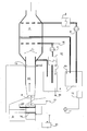
- the drawing shows schematically an internal combustion engine 9, which may be especially a large diesel engine, to which inlet air 21 is conducted and from which exhaust gases 22 are discharged as a result of the combustion process.
- the engine is also provided with a turbocompressor 8.
- the exhaust gases 22 are conducted to an exhaust gas scrubber 1, in which they are washed, in order to remove sulphur dioxides SOx in particular, before being discharged to the environment.
- an exhaust gas scrubber 1 In the drawing only one actual washing cycle is shown, but the washing may, if so required, be performed in one or several stages, and it is carried out mainly by using water.
- the exhaust gases In the scrubber the exhaust gases also cool in conjunction with the washing itself.
- the scrubber is placed vertically and it illustrates only one actual washing stage in the lower part of the scrubber.
- the flow circulation of the wash water comprises a wash water tank 6, from which the wash water is pumped by a pump 3 to the lower part of the scrubber.
- the cycle also includes a heat exchanger 12, by which additional heat is delivered to the scrubber for increasing the amount of evaporating wash water to be recovered, or the wash water may be cooled down in order to partially condensate the steam already at the washing stage.
- make-up water 17 may be added to the tank 6.
- the exhaust gas flow saturated by water vapour is taken further to be cooled in a cooling section 2, which may in practise consist of the upper part of the scrubber 1, or of the latter end thereof, if the scrubber is arranged in horizontal position.
- a cooling section 2 which may in practise consist of the upper part of the scrubber 1, or of the latter end thereof, if the scrubber is arranged in horizontal position.
- the exhaust gases and the water vapour therein is already clean, whereby water vapour is recovered into a tank 7 to be further introduced to the inlet air 21 of the engine 9 after the compressor 8, as is explained in more detail further below.
- the cooling of the exhaust gases may occur in various ways.
- clean water is pumped from the tank 7 by a pump 4 via a heat exchanger 5 to the cooling unit 2, whereby the cooling of the exhaust gases saturated by water vapour is carried out by means of water drops.
- Both the water used for the cooling and the clean water condensated by means of it from water vapour into water are recovered and conducted to the tank 7.
- Make-up water 19 is introduced into the tank 7, as required. After the cooling unit 2 the exhaust gases are discharged to the atmosphere.
- seawater may advantageously be used as a cooling liquid of the heat exchanger 5 in both above-mentioned cases.
- seawater may be used in the tank 6 to be pumped to the scrubber and as make-up water 17. If the seawater is sufficiently saline, additives 18 are required in this case only to a minor extent or not at all.
- the clean water collected in the tank 7 is led through a filter 10 for clean water by means of a pump 11 to be introduced to the inlet air 21 of the engine after the compressor 8.
- the introduction may preferably be performed in two stages so that additional heating of the flow is provided between the stages. The purpose of this is to get more water evaporated and supplied to the inlet air after the compressor 8, whereby also the reduction of NOx-emissions in the combustion process of the engine is more efficient.
- the additional heat may advantageously be delivered by using the steam produced by means of the exhaust gases 22 in a heat exchanger 13, which requires a separate water circulation with a feed water tank 15.
- the additional heat may advantageously be provided also by conducting at least a part of the exhaust gases 22 via an exhaust gas heat exchanger 20 arranged in the inlet air passage of the engine. Naturally, no separate fluid circulation is required for transferring heat energy in this case.
Landscapes
- Engineering & Computer Science (AREA)
- Chemical & Material Sciences (AREA)
- Combustion & Propulsion (AREA)
- Mechanical Engineering (AREA)
- General Engineering & Computer Science (AREA)
- Water Supply & Treatment (AREA)
- Health & Medical Sciences (AREA)
- Public Health (AREA)
- Biomedical Technology (AREA)
- Environmental & Geological Engineering (AREA)
- Analytical Chemistry (AREA)
- General Chemical & Material Sciences (AREA)
- Oil, Petroleum & Natural Gas (AREA)
- Chemical Kinetics & Catalysis (AREA)
- Treating Waste Gases (AREA)
- Exhaust Gas After Treatment (AREA)
Claims (12)
- Verfahren zum Behandeln der Ansaugluft (21) und der Abgase (22) eines großen aufgeladenen Verbrennungsmotors (9), insbesondere eines Dieselmotors, in einem System, in dem Wasser in einer geeigneten Form, zum Beispiel als Wasserdampf oder Wassernebel, nach dem Kompressor (8) zur Ansaugluft des Motors geliefert wird, um die Ansaugluft (21) zu kühlen und zu sättigen, und wobei die Abgase (22) vom Motor zu einem Abgasreiniger (1, 2) geführt werden, um zumindest hauptsächlich durch Wasser gewaschen und gekühlt zu werden, dadurch gekennzeichnet, dass die Abgase (22) im Abgasreiniger (1, 2) in zumindest zwei aufeinanderfolgenden Stufen abgekühlt werden, die vorzugsweise in der senkrechten Richtung angeordnet sind, um den Wasserdampf in den Abgasen zu kondensieren, um sauberes Wasser rückzugewinnen, dass das saubere Wasser, das im oberen Teil (2) des Abgasreinigers oder in der letzteren Stufe rückgewonnen wurde, in zwei aufeinanderfolgenden Stufen in der Strömungsrichtung zur Ansaugluft (21) des Motors geführt wird, und dass der Ansaugluft (21) über einen Wärmeaustauscher (14, 20), der zwischen diesen aufeinanderfolgenden Stufen angeordnet ist, zusätzliche Wärme geliefert wird, damit das Kühlen und Sättigen der Ansaugluft (21) hauptsächlich durch das Wasser, das vom Abgasreiniger rückgewonnen wurde, durchgeführt wird.
- Verfahren nach Anspruch 1, dadurch gekennzeichnet, dass ein Teil des Wasserdampfs in den Abgasen im unteren Teil (1) des Abgasreinigers (1, 2) rückgewonnen wird und zum Waschen der Abgase im unteren Teil (1) des Abgasreinigers (1, 2) verwendet wird.
- Verfahren nach Anspruch 1 oder 2, dadurch gekennzeichnet, dass die zusätzliche Wärme durch Verwenden des Dampfs, der mittels der Abgase (22) erzeugt wird, geliefert wird.
- Verfahren nach Anspruch 1 oder 2, dadurch gekennzeichnet, dass die zusätzliche Wärme durch Führen zumindest eines Teils der Abgase über einen Wärmeaustauscher (20), der im Ansaugluftdurchgang des Motors angeordnet ist, bereitgestellt wird.
- Verfahren nach einem der vorhergehenden Ansprüche, dadurch gekennzeichnet, dass zusätzliche Wärme zum Waschabschnitt (1) des Abgasreinigers (1, 2) geliefert wird, und dass die zusätzliche Wärme insbesondere durch Kühlen des Motors rückgewonnene Wärme, sogenannte HT-Wärme, ist, die zum Wasserkreislauf im Waschabschnitt (1) des Abgasreinigers (1, 2) übertragen wird.
- Verfahren nach einem der vorhergehenden Ansprüche, dadurch gekennzeichnet, dass das Verfahren auf ein Wasserfahrzeug oder einen anderen im Wasser angeordneten Aufbau angewendet wird, und dass das Kühlen der Abgase im Abgasreiniger (1, 2) zumindest teilweise durch Meerwasser bereitgestellt wird.
- Anordnung zum Behandeln der Ansaugluft (21) und der Abgase (22) eines großen aufgeladenen Verbrennungsmotors (9), insbesondere eines Dieselmotors, in einem System, in dem Wasser in einer geeigneten Form, zum Beispiel als Wasserdampf oder Wassernebel, nach dem Kompressor (8) zur Ansaugluft des Motors geliefert wird, um die Ansaugluft (21) zu kühlen und zu sättigen, und wobei die Abgase (22) vom Motor zu einem Abgasreiniger (1, 2) geführt werden, um zumindest hauptsächlich durch Wasser gewaschen und gekühlt zu werden, dadurch gekennzeichnet, dass veranlasst wird, dass die Abgase (22) im Abgasreiniger (1, 2) in zumindest zwei aufeinanderfolgenden Stufen, die vorzugsweise in der senkrechten Richtung angeordnet sind, gekühlt werden, um den Wasserdampf in den Abgasen zu kondensieren, um reines Wasser rückzugewinnen, dass veranlasst wird, dass das kondensierte reine Wasser, das im oberen Teil (2) des Abgasreinigers oder in der letzteren Stufe rückgewonnen wurde, in zwei aufeinanderfolgenden Stufen in der Strömungsrichtung zur Ansaugluft (21) des Motors geliefert wird, und dass veranlasst wird (14, 20), dass zusätzliche Wärme mittels eines Wärmeaustauschers (14, 20), der zwischen diesen beiden aufeinanderfolgenden Wasserlieferstufen angeordnet ist, direkt zur Ansaugluft geliefert wird, so dass das Kühlen und Sättigen der Ansaugluft (21) zumindest hauptsächlich durch das Wasser, das vom Abgasreiniger (1, 2) rückgewonnen wurde, bereitgestellt wird.
- Anordnung nach Anspruch 7, dadurch gekennzeichnet, dass veranlasst wird, dass ein Teil des Wasserdampfs in den Abgasen im unteren Teil des Abgasreinigers (1, 2) rückgewonnen und zum Waschen und Kühlen der Abgase im unteren Teil des Abgasreinigers (1, 2) verwendet wird.
- Anordnung nach Anspruch 7 oder 8, dadurch gekennzeichnet, dass veranlasst wird, dass die zusätzliche Wärme durch einen Dampfwärmeaustauscher (13), der im heißen Abgasstrom (22) angeordnet ist, bereitgestellt wird.
- Anordnung nach Anspruch 7 oder 8, dadurch gekennzeichnet, dass zur Bereitstellung von zusätzlicher Wärme veranlasst wird, dass zumindest ein Teil der Abgase über einen Wärmeaustauscher (20), der im Ansaugluftdurchgang des Motors angeordnet ist, geführt wird.
- Anordnung nach einem der vorhergehenden Ansprüche 7 bis 10, dadurch gekennzeichnet, dass veranlasst wird, dass zusätzliche Wärme zum Waschabschnitt des Abgasreinigers (1, 2) geliefert wird, und dass die zusätzliche Wärme insbesondere durch Kühlen des Motors rückgewonnene Wärme, sogenannte HT-Wärme, ist, deren Übertragung (12) zum Wasserkreislauf im Waschabschnitt des Abgasreinigers (1, 2) veranlasst wird.
- Anordnung nach einem der vorhergehenden Ansprüche 7 bis 11, dadurch gekennzeichnet, dass die Anordnung auf ein Wasserfahrzeug oder einen anderen im Wasser angeordneten Aufbau angewendet wird, und dass veranlasst wird, dass das Kühlen der Abgase des Abgasreinigers (1, 2) zumindest zum Teil durch Meerwasser bereitgestellt wird.
Priority Applications (1)
| Application Number | Priority Date | Filing Date | Title |
|---|---|---|---|
| PL06794152T PL1952007T3 (pl) | 2005-10-21 | 2006-10-10 | Sposób i układ do obróbki powietrza dolotowego i gazów spalinowych silnika spalinowego wewnętrznego spalania |
Applications Claiming Priority (2)
| Application Number | Priority Date | Filing Date | Title |
|---|---|---|---|
| FI20055567A FI120213B (fi) | 2005-10-21 | 2005-10-21 | Menetelmä ja järjestely polttomoottorin syöttöilman ja pakokaasujen käsittelemiseksi |
| PCT/FI2006/050435 WO2007045721A1 (en) | 2005-10-21 | 2006-10-10 | Method and arrangement for treating the inlet air and exhaust gases of an internal combustion engine |
Publications (2)
| Publication Number | Publication Date |
|---|---|
| EP1952007A1 EP1952007A1 (de) | 2008-08-06 |
| EP1952007B1 true EP1952007B1 (de) | 2011-07-27 |
Family
ID=35185273
Family Applications (1)
| Application Number | Title | Priority Date | Filing Date |
|---|---|---|---|
| EP06794152A Not-in-force EP1952007B1 (de) | 2005-10-21 | 2006-10-10 | Verfahren und anordnung zur behandlung von einlassluft und abgasen eines verbrennungsmotors |
Country Status (7)
| Country | Link |
|---|---|
| EP (1) | EP1952007B1 (de) |
| AT (1) | ATE518055T1 (de) |
| DK (1) | DK1952007T3 (de) |
| FI (1) | FI120213B (de) |
| NO (1) | NO20082274L (de) |
| PL (1) | PL1952007T3 (de) |
| WO (1) | WO2007045721A1 (de) |
Cited By (1)
| Publication number | Priority date | Publication date | Assignee | Title |
|---|---|---|---|---|
| US9982582B2 (en) | 2013-03-08 | 2018-05-29 | Alfa Laval Corporate Ab | Cleaning system and method for reduction of SOx in exhaust gases |
Families Citing this family (11)
| Publication number | Priority date | Publication date | Assignee | Title |
|---|---|---|---|---|
| DE102009017936A1 (de) * | 2009-04-17 | 2010-10-21 | Man Diesel Se | Luftführung für eine aufgeladene Brennkraftmaschine |
| FI124473B (fi) | 2009-12-15 | 2014-09-15 | Wärtsilä Finland Oy | Pesuriyksikköjärjestely ja menetelmä pakokaasun puhdistamiseksi pesuriyksikköjärjestelyssä |
| EP3461795A1 (de) | 2010-02-25 | 2019-04-03 | Alfa Laval Corporate AB | Verfahren zum entlüften einer wäscherflüssigkeit und verwendung eines entlüftungszentrifugalabscheiders |
| GB2481980A (en) * | 2010-07-12 | 2012-01-18 | Matthew P Wood | I.c. engine in which water is recovered from the exhaust and re-used |
| FI124749B (fi) | 2011-02-23 | 2015-01-15 | Wärtsilä Finland Oy | Pesurisysteemi pakokaasujen käsittelemiseksi vesialuksessa ja menetelmä pakokaasujen käsittelemiseksi vesialuksen pesurisysteemisessä |
| FI124227B (fi) | 2011-08-17 | 2014-05-15 | Wärtsilä Finland Oy | Menetelmä polttomoottorin käyttämiseksi ja polttomoottorijärjestely |
| FI123737B (fi) | 2012-02-13 | 2013-10-15 | Oy Langh Ship Ab | Menetelmä laivojen pakokaasuissa olevien epäpuhtauksien käsittelemiseksi, ja laiva, jossa pakokaasupesuri |
| DE102012009318B4 (de) | 2012-05-10 | 2021-05-06 | MAN Energy Solutions, branch of MAN Energy Solutions SE, Germany | Dieselmotor und Verfahren zur Leistungssteigerung eines bestehenden Dieselmotors |
| EP2703063A1 (de) * | 2012-09-04 | 2014-03-05 | Alstom Technology Ltd | Entschwefelung und Kühlung von Prozessgas |
| KR101945648B1 (ko) | 2014-12-08 | 2019-02-07 | 바르실라 핀랜드 오이 | 선박의 내연 피스톤 엔진의 배기 가스를 처리하는 장치 및 배기 가스를 처리하는 장치를 작동시키는 방법 |
| EP3455473B1 (de) | 2018-04-09 | 2020-08-05 | Wärtsilä Finland Oy | Wasserdurchführungsmodul und verfahren zur anordnung einer wasserdurchführung zu einem rumpf eines schiffes |
Family Cites Families (4)
| Publication number | Priority date | Publication date | Assignee | Title |
|---|---|---|---|---|
| DE4231681A1 (de) * | 1992-07-29 | 1994-03-24 | Helmut Dallinga | Verfahren und Vorrichtung zur Durchführung des Verfahrens zum Klimatisieren der den Brennkammern von Brennkraftmaschinen zuzuführenden Frischluft bzw. des Frischluft-Kraftstoffgemisches durch direkten und/oder indirekten Austausch von Wärme und Feuchte |
| DK170218B1 (da) * | 1993-06-04 | 1995-06-26 | Man B & W Diesel Gmbh | Stor trykladet dieselmotor |
| DE19918591A1 (de) * | 1999-04-23 | 2000-10-26 | Fev Motorentech Gmbh | Verfahren zur Optimierung des Betriebsprozesses einer Kolbenbrennkraftmaschine durch Wassereindüsung |
| DE19939289C1 (de) * | 1999-08-19 | 2000-10-05 | Mak Motoren Gmbh & Co Kg | Verfahren und Einrichtung zur Aufbereitung von Gasgemischen |
-
2005
- 2005-10-21 FI FI20055567A patent/FI120213B/fi not_active IP Right Cessation
-
2006
- 2006-10-10 AT AT06794152T patent/ATE518055T1/de not_active IP Right Cessation
- 2006-10-10 WO PCT/FI2006/050435 patent/WO2007045721A1/en not_active Ceased
- 2006-10-10 DK DK06794152.6T patent/DK1952007T3/da active
- 2006-10-10 EP EP06794152A patent/EP1952007B1/de not_active Not-in-force
- 2006-10-10 PL PL06794152T patent/PL1952007T3/pl unknown
-
2008
- 2008-05-21 NO NO20082274A patent/NO20082274L/no not_active Application Discontinuation
Cited By (1)
| Publication number | Priority date | Publication date | Assignee | Title |
|---|---|---|---|---|
| US9982582B2 (en) | 2013-03-08 | 2018-05-29 | Alfa Laval Corporate Ab | Cleaning system and method for reduction of SOx in exhaust gases |
Also Published As
| Publication number | Publication date |
|---|---|
| WO2007045721A1 (en) | 2007-04-26 |
| PL1952007T3 (pl) | 2011-12-30 |
| FI120213B (fi) | 2009-07-31 |
| EP1952007A1 (de) | 2008-08-06 |
| FI20055567L (fi) | 2007-04-22 |
| FI20055567A0 (fi) | 2005-10-21 |
| NO20082274L (no) | 2008-05-21 |
| ATE518055T1 (de) | 2011-08-15 |
| DK1952007T3 (da) | 2011-09-26 |
Similar Documents
| Publication | Publication Date | Title |
|---|---|---|
| JP4997336B2 (ja) | 排ガス再循環システムを備える大型2サイクルディーゼル機関 | |
| EP1952007B1 (de) | Verfahren und anordnung zur behandlung von einlassluft und abgasen eines verbrennungsmotors | |
| US7861511B2 (en) | System for recirculating the exhaust of a turbomachine | |
| US7976809B2 (en) | Method and an equipment for reducing the sulphur dioxide emissions of a marine engine | |
| US8056318B2 (en) | System for reducing the sulfur oxides emissions generated by a turbomachine | |
| US20100230506A1 (en) | Machinery arrangement of a marine vessel | |
| NL8001472A (nl) | Installatie voor warmteterugwinning bij verbrandingsmachine met compressor. | |
| CA2988069C (en) | Turbine system and method | |
| EP2636870A1 (de) | Herstellung von Abgas aus einer Gasturbine für die Abgasrückführung | |
| EP1957181B1 (de) | Verfahren und anordnung zur reinigung der abgase einer brennkraftmaschine | |
| EP2404653A1 (de) | Integrierte Rauchgasentfeuchtung und Nasskühlturmsystem | |
| CN104712382B (zh) | 实现船舶低速柴油机超低排放及废热回收的联合循环系统 | |
| Mirolli | Ammonia-water based thermal conversion technology: Applications in waste heat recovery for the cement industry | |
| US20120042779A1 (en) | Integrated flue gas dehumidification and wet cooling tower system | |
| US12528041B2 (en) | Carbon capture system and method with exhaust gas recirculation | |
| KR20180006059A (ko) | 엔진의 배기가스 재순환 시스템 및 방법 | |
| CN107486016B (zh) | 一种适用于高硫燃油的船用低速柴油机的低温脱硫脱硝技术 | |
| JP2008018372A (ja) | ディーゼル機関における掃気空気冷却器を利用した造水装置および清水の噴霧、噴射装置 | |
| Radchenko et al. | Improving energy efficiency of marine diesel engines by utilizing the recirculation gas heat in absorption chiller | |
| Behrendt et al. | The effect of selected methods of waste heat utilization on waste heat boiler steam production | |
| Park et al. | NOx Reduction of a Medium Speed Diesel Engine Using a Charge Air Moisturizer System | |
| KR20180095808A (ko) | 응축 열 회수 스팀 발생기 |
Legal Events
| Date | Code | Title | Description |
|---|---|---|---|
| PUAI | Public reference made under article 153(3) epc to a published international application that has entered the european phase |
Free format text: ORIGINAL CODE: 0009012 |
|
| 17P | Request for examination filed |
Effective date: 20080508 |
|
| AK | Designated contracting states |
Kind code of ref document: A1 Designated state(s): AT BE BG CH CY CZ DE DK EE ES FI FR GB GR HU IE IS IT LI LT LU LV MC NL PL PT RO SE SI SK TR |
|
| RAP1 | Party data changed (applicant data changed or rights of an application transferred) |
Owner name: STX FINLAND CRUISE OY |
|
| RAP1 | Party data changed (applicant data changed or rights of an application transferred) |
Owner name: STX FINLAND OY |
|
| 17Q | First examination report despatched |
Effective date: 20100803 |
|
| GRAP | Despatch of communication of intention to grant a patent |
Free format text: ORIGINAL CODE: EPIDOSNIGR1 |
|
| DAX | Request for extension of the european patent (deleted) | ||
| GRAS | Grant fee paid |
Free format text: ORIGINAL CODE: EPIDOSNIGR3 |
|
| GRAA | (expected) grant |
Free format text: ORIGINAL CODE: 0009210 |
|
| AK | Designated contracting states |
Kind code of ref document: B1 Designated state(s): AT BE BG CH CY CZ DE DK EE ES FI FR GB GR HU IE IS IT LI LT LU LV MC NL PL PT RO SE SI SK TR |
|
| REG | Reference to a national code |
Ref country code: GB Ref legal event code: FG4D |
|
| REG | Reference to a national code |
Ref country code: CH Ref legal event code: EP |
|
| REG | Reference to a national code |
Ref country code: DE Ref legal event code: R096 Ref document number: 602006023391 Country of ref document: DE Effective date: 20110915 |
|
| REG | Reference to a national code |
Ref country code: NL Ref legal event code: T3 |
|
| REG | Reference to a national code |
Ref country code: DK Ref legal event code: T3 |
|
| PGFP | Annual fee paid to national office [announced via postgrant information from national office to epo] |
Ref country code: NL Payment date: 20110927 Year of fee payment: 6 |
|
| REG | Reference to a national code |
Ref country code: PL Ref legal event code: T3 |
|
| REG | Reference to a national code |
Ref country code: AT Ref legal event code: MK05 Ref document number: 518055 Country of ref document: AT Kind code of ref document: T Effective date: 20110727 |
|
| PG25 | Lapsed in a contracting state [announced via postgrant information from national office to epo] |
Ref country code: PT Free format text: LAPSE BECAUSE OF FAILURE TO SUBMIT A TRANSLATION OF THE DESCRIPTION OR TO PAY THE FEE WITHIN THE PRESCRIBED TIME-LIMIT Effective date: 20111128 Ref country code: LT Free format text: LAPSE BECAUSE OF FAILURE TO SUBMIT A TRANSLATION OF THE DESCRIPTION OR TO PAY THE FEE WITHIN THE PRESCRIBED TIME-LIMIT Effective date: 20110727 Ref country code: FI Free format text: LAPSE BECAUSE OF FAILURE TO SUBMIT A TRANSLATION OF THE DESCRIPTION OR TO PAY THE FEE WITHIN THE PRESCRIBED TIME-LIMIT Effective date: 20110727 Ref country code: BE Free format text: LAPSE BECAUSE OF FAILURE TO SUBMIT A TRANSLATION OF THE DESCRIPTION OR TO PAY THE FEE WITHIN THE PRESCRIBED TIME-LIMIT Effective date: 20110727 Ref country code: SE Free format text: LAPSE BECAUSE OF FAILURE TO SUBMIT A TRANSLATION OF THE DESCRIPTION OR TO PAY THE FEE WITHIN THE PRESCRIBED TIME-LIMIT Effective date: 20110727 Ref country code: IS Free format text: LAPSE BECAUSE OF FAILURE TO SUBMIT A TRANSLATION OF THE DESCRIPTION OR TO PAY THE FEE WITHIN THE PRESCRIBED TIME-LIMIT Effective date: 20111127 |
|
| PGFP | Annual fee paid to national office [announced via postgrant information from national office to epo] |
Ref country code: DK Payment date: 20111014 Year of fee payment: 6 Ref country code: FR Payment date: 20111103 Year of fee payment: 6 |
|
| PG25 | Lapsed in a contracting state [announced via postgrant information from national office to epo] |
Ref country code: SI Free format text: LAPSE BECAUSE OF FAILURE TO SUBMIT A TRANSLATION OF THE DESCRIPTION OR TO PAY THE FEE WITHIN THE PRESCRIBED TIME-LIMIT Effective date: 20110727 Ref country code: AT Free format text: LAPSE BECAUSE OF FAILURE TO SUBMIT A TRANSLATION OF THE DESCRIPTION OR TO PAY THE FEE WITHIN THE PRESCRIBED TIME-LIMIT Effective date: 20110727 Ref country code: GR Free format text: LAPSE BECAUSE OF FAILURE TO SUBMIT A TRANSLATION OF THE DESCRIPTION OR TO PAY THE FEE WITHIN THE PRESCRIBED TIME-LIMIT Effective date: 20111028 Ref country code: LV Free format text: LAPSE BECAUSE OF FAILURE TO SUBMIT A TRANSLATION OF THE DESCRIPTION OR TO PAY THE FEE WITHIN THE PRESCRIBED TIME-LIMIT Effective date: 20110727 Ref country code: CY Free format text: LAPSE BECAUSE OF FAILURE TO SUBMIT A TRANSLATION OF THE DESCRIPTION OR TO PAY THE FEE WITHIN THE PRESCRIBED TIME-LIMIT Effective date: 20110727 |
|
| PG25 | Lapsed in a contracting state [announced via postgrant information from national office to epo] |
Ref country code: SK Free format text: LAPSE BECAUSE OF FAILURE TO SUBMIT A TRANSLATION OF THE DESCRIPTION OR TO PAY THE FEE WITHIN THE PRESCRIBED TIME-LIMIT Effective date: 20110727 Ref country code: CZ Free format text: LAPSE BECAUSE OF FAILURE TO SUBMIT A TRANSLATION OF THE DESCRIPTION OR TO PAY THE FEE WITHIN THE PRESCRIBED TIME-LIMIT Effective date: 20110727 |
|
| PG25 | Lapsed in a contracting state [announced via postgrant information from national office to epo] |
Ref country code: EE Free format text: LAPSE BECAUSE OF FAILURE TO SUBMIT A TRANSLATION OF THE DESCRIPTION OR TO PAY THE FEE WITHIN THE PRESCRIBED TIME-LIMIT Effective date: 20110727 Ref country code: RO Free format text: LAPSE BECAUSE OF FAILURE TO SUBMIT A TRANSLATION OF THE DESCRIPTION OR TO PAY THE FEE WITHIN THE PRESCRIBED TIME-LIMIT Effective date: 20110727 Ref country code: MC Free format text: LAPSE BECAUSE OF NON-PAYMENT OF DUE FEES Effective date: 20111031 |
|
| REG | Reference to a national code |
Ref country code: CH Ref legal event code: PL |
|
| PLBE | No opposition filed within time limit |
Free format text: ORIGINAL CODE: 0009261 |
|
| STAA | Information on the status of an ep patent application or granted ep patent |
Free format text: STATUS: NO OPPOSITION FILED WITHIN TIME LIMIT |
|
| GBPC | Gb: european patent ceased through non-payment of renewal fee |
Effective date: 20111027 |
|
| 26N | No opposition filed |
Effective date: 20120502 |
|
| PG25 | Lapsed in a contracting state [announced via postgrant information from national office to epo] |
Ref country code: LI Free format text: LAPSE BECAUSE OF NON-PAYMENT OF DUE FEES Effective date: 20111031 Ref country code: CH Free format text: LAPSE BECAUSE OF NON-PAYMENT OF DUE FEES Effective date: 20111031 |
|
| REG | Reference to a national code |
Ref country code: IE Ref legal event code: MM4A |
|
| REG | Reference to a national code |
Ref country code: DE Ref legal event code: R097 Ref document number: 602006023391 Country of ref document: DE Effective date: 20120502 |
|
| PG25 | Lapsed in a contracting state [announced via postgrant information from national office to epo] |
Ref country code: GB Free format text: LAPSE BECAUSE OF NON-PAYMENT OF DUE FEES Effective date: 20111027 |
|
| PG25 | Lapsed in a contracting state [announced via postgrant information from national office to epo] |
Ref country code: IE Free format text: LAPSE BECAUSE OF NON-PAYMENT OF DUE FEES Effective date: 20111010 |
|
| PG25 | Lapsed in a contracting state [announced via postgrant information from national office to epo] |
Ref country code: ES Free format text: LAPSE BECAUSE OF FAILURE TO SUBMIT A TRANSLATION OF THE DESCRIPTION OR TO PAY THE FEE WITHIN THE PRESCRIBED TIME-LIMIT Effective date: 20111107 |
|
| REG | Reference to a national code |
Ref country code: NL Ref legal event code: V1 Effective date: 20130501 |
|
| PG25 | Lapsed in a contracting state [announced via postgrant information from national office to epo] |
Ref country code: LU Free format text: LAPSE BECAUSE OF NON-PAYMENT OF DUE FEES Effective date: 20111010 |
|
| REG | Reference to a national code |
Ref country code: DK Ref legal event code: EBP |
|
| PG25 | Lapsed in a contracting state [announced via postgrant information from national office to epo] |
Ref country code: BG Free format text: LAPSE BECAUSE OF FAILURE TO SUBMIT A TRANSLATION OF THE DESCRIPTION OR TO PAY THE FEE WITHIN THE PRESCRIBED TIME-LIMIT Effective date: 20111027 |
|
| REG | Reference to a national code |
Ref country code: FR Ref legal event code: ST Effective date: 20130628 |
|
| PG25 | Lapsed in a contracting state [announced via postgrant information from national office to epo] |
Ref country code: DE Free format text: LAPSE BECAUSE OF NON-PAYMENT OF DUE FEES Effective date: 20130501 |
|
| REG | Reference to a national code |
Ref country code: DE Ref legal event code: R119 Ref document number: 602006023391 Country of ref document: DE Effective date: 20130501 |
|
| PG25 | Lapsed in a contracting state [announced via postgrant information from national office to epo] |
Ref country code: FR Free format text: LAPSE BECAUSE OF NON-PAYMENT OF DUE FEES Effective date: 20121031 Ref country code: NL Free format text: LAPSE BECAUSE OF NON-PAYMENT OF DUE FEES Effective date: 20130501 Ref country code: IT Free format text: LAPSE BECAUSE OF NON-PAYMENT OF DUE FEES Effective date: 20121010 |
|
| PG25 | Lapsed in a contracting state [announced via postgrant information from national office to epo] |
Ref country code: TR Free format text: LAPSE BECAUSE OF FAILURE TO SUBMIT A TRANSLATION OF THE DESCRIPTION OR TO PAY THE FEE WITHIN THE PRESCRIBED TIME-LIMIT Effective date: 20110727 |
|
| PG25 | Lapsed in a contracting state [announced via postgrant information from national office to epo] |
Ref country code: HU Free format text: LAPSE BECAUSE OF FAILURE TO SUBMIT A TRANSLATION OF THE DESCRIPTION OR TO PAY THE FEE WITHIN THE PRESCRIBED TIME-LIMIT Effective date: 20110727 Ref country code: DK Free format text: LAPSE BECAUSE OF NON-PAYMENT OF DUE FEES Effective date: 20121031 |
|
| PG25 | Lapsed in a contracting state [announced via postgrant information from national office to epo] |
Ref country code: PL Free format text: LAPSE BECAUSE OF NON-PAYMENT OF DUE FEES Effective date: 20121010 |