EP1951351B1 - Wire guide having distal coupling tip - Google Patents
Wire guide having distal coupling tip Download PDFInfo
- Publication number
- EP1951351B1 EP1951351B1 EP06826986A EP06826986A EP1951351B1 EP 1951351 B1 EP1951351 B1 EP 1951351B1 EP 06826986 A EP06826986 A EP 06826986A EP 06826986 A EP06826986 A EP 06826986A EP 1951351 B1 EP1951351 B1 EP 1951351B1
- Authority
- EP
- European Patent Office
- Prior art keywords
- wire guide
- wire
- coupling
- main body
- loop
- Prior art date
- Legal status (The legal status is an assumption and is not a legal conclusion. Google has not performed a legal analysis and makes no representation as to the accuracy of the status listed.)
- Not-in-force
Links
- 230000008878 coupling Effects 0.000 title claims abstract description 48
- 238000010168 coupling process Methods 0.000 title claims abstract description 48
- 238000005859 coupling reaction Methods 0.000 title claims abstract description 48
- 238000000034 method Methods 0.000 claims description 27
- 238000004804 winding Methods 0.000 claims description 8
- 230000000153 supplemental effect Effects 0.000 description 7
- 210000005166 vasculature Anatomy 0.000 description 7
- 208000027418 Wounds and injury Diseases 0.000 description 4
- 238000013152 interventional procedure Methods 0.000 description 4
- 238000002399 angioplasty Methods 0.000 description 3
- 238000010276 construction Methods 0.000 description 3
- 238000012986 modification Methods 0.000 description 3
- 230000004048 modification Effects 0.000 description 3
- 230000015572 biosynthetic process Effects 0.000 description 2
- 230000003902 lesion Effects 0.000 description 2
- HLXZNVUGXRDIFK-UHFFFAOYSA-N nickel titanium Chemical compound [Ti].[Ti].[Ti].[Ti].[Ti].[Ti].[Ti].[Ti].[Ti].[Ti].[Ti].[Ni].[Ni].[Ni].[Ni].[Ni].[Ni].[Ni].[Ni].[Ni].[Ni].[Ni].[Ni].[Ni].[Ni] HLXZNVUGXRDIFK-UHFFFAOYSA-N 0.000 description 2
- 229910001000 nickel titanium Inorganic materials 0.000 description 2
- 239000007787 solid Substances 0.000 description 2
- 208000012287 Prolapse Diseases 0.000 description 1
- 230000001154 acute effect Effects 0.000 description 1
- 229910045601 alloy Inorganic materials 0.000 description 1
- 239000000956 alloy Substances 0.000 description 1
- 239000011248 coating agent Substances 0.000 description 1
- 238000000576 coating method Methods 0.000 description 1
- 239000007799 cork Substances 0.000 description 1
- 230000006378 damage Effects 0.000 description 1
- 208000014674 injury Diseases 0.000 description 1
- 239000000463 material Substances 0.000 description 1
- 239000002184 metal Substances 0.000 description 1
- 230000037361 pathway Effects 0.000 description 1
- 238000005476 soldering Methods 0.000 description 1
- 239000010935 stainless steel Substances 0.000 description 1
- 229910001220 stainless steel Inorganic materials 0.000 description 1
- 238000003466 welding Methods 0.000 description 1
Images
Classifications
-
- A—HUMAN NECESSITIES
- A61—MEDICAL OR VETERINARY SCIENCE; HYGIENE
- A61M—DEVICES FOR INTRODUCING MEDIA INTO, OR ONTO, THE BODY; DEVICES FOR TRANSDUCING BODY MEDIA OR FOR TAKING MEDIA FROM THE BODY; DEVICES FOR PRODUCING OR ENDING SLEEP OR STUPOR
- A61M25/00—Catheters; Hollow probes
- A61M25/01—Introducing, guiding, advancing, emplacing or holding catheters
- A61M25/09—Guide wires
- A61M25/0905—Guide wires extendable, e.g. mechanisms for extension
-
- A—HUMAN NECESSITIES
- A61—MEDICAL OR VETERINARY SCIENCE; HYGIENE
- A61M—DEVICES FOR INTRODUCING MEDIA INTO, OR ONTO, THE BODY; DEVICES FOR TRANSDUCING BODY MEDIA OR FOR TAKING MEDIA FROM THE BODY; DEVICES FOR PRODUCING OR ENDING SLEEP OR STUPOR
- A61M25/00—Catheters; Hollow probes
- A61M25/01—Introducing, guiding, advancing, emplacing or holding catheters
- A61M25/09—Guide wires
- A61M2025/09058—Basic structures of guide wires
- A61M2025/09083—Basic structures of guide wires having a coil around a core
-
- A—HUMAN NECESSITIES
- A61—MEDICAL OR VETERINARY SCIENCE; HYGIENE
- A61M—DEVICES FOR INTRODUCING MEDIA INTO, OR ONTO, THE BODY; DEVICES FOR TRANSDUCING BODY MEDIA OR FOR TAKING MEDIA FROM THE BODY; DEVICES FOR PRODUCING OR ENDING SLEEP OR STUPOR
- A61M25/00—Catheters; Hollow probes
- A61M25/01—Introducing, guiding, advancing, emplacing or holding catheters
- A61M25/09—Guide wires
- A61M2025/09175—Guide wires having specific characteristics at the distal tip
- A61M2025/09183—Guide wires having specific characteristics at the distal tip having tools at the distal tip
Definitions
- This invention relates generally to a wire guide for use in intracorporeal procedures, and more particularly relates to the construction of a wire guide to be coupled to a previously introduced wire guide for assistance during interventional procedures in vessels with proximal tortuosity, or as a more substantial wire guide for angioplasty procedures, stenting procedures, and other device placement procedures and their related devices.
- Wire guides are therefore typically used to navigate the vasculature of a patient during percutaneous interventional procedures. Once the wire guide has been introduced, it may then be used to introduce one or more medical catheter devices. Thus, most wire guides are typically 0.014 inches in diameter and have a lubricious coating to enhance wire guide introduction movement. Conventional 0.014 inch floppy wire guides must have sufficient flexibility and torque control for navigation through tortuous vessels. At the same - time, the wire guide must have a certain amount of rigidity to pass through lesions, straighten extremely tortuous vessels, and support medical catheter devices that are introduced over the wire guide.
- wire guides are subjected to potentially conflicting requirements.
- Conventional 0.014 inch floppy wire guides are usually sufficient for navigation of moderately tortuous vessels.
- the wire guide tip may prolapse away from the site to which it is guiding the device.
- balloon angioplasty in vessels with proximal tortuosity has been associated with a higher incidence of acute complications and procedural failure due to the inability to cross lesions with a conventional floppy wire guide, and due to the inability of the wire guide to provide adequate support to the balloon catheter.
- Heavy-duty wire guides, on the other,hand are generally not well suited as primary wire guides because of their stiffness and potential for causing injury to the vessel during introduction.
- a supplemental wire guide will straighten out the vessel curves and ease further wire guide movement. Additionally, the supplemental wire guide provides greater support and enhances the tracking of balloons, stents, stent delivery devices, atherectomy devices, and other medical catheter devices as compared to a conventional floppy wire guide. This technique is commonly referred to as the "Buddy Wire" technique, details of which are disclosed in U.S. Patent Application Serial No. 11/081,146, filed March 16, 2005 .
- the navigation of the supplemental wire guide parallel to the first wire guide is an exacting and time consuming process in which additional difficulties are encountered.
- the second wire guide can cork screw or coil around the first wire guide, which may result in immobilization or unintended movement of the first wire guide, which in turn may require the retraction and re-feeding of the supplemental wire guide and/or the primary wire guide.
- either of the wire guides may become contaminated and the entire process may need to be restarted with sterile components.
- the time consumed by this process can be critical to the success of the procedure.
- the larger open space of the heart makes identical placement of the supplemental wire guide somewhat difficult.
- Document EP 0 436 303 A1 further discloses a guidewire for tracking an indwelling device such as a catheter previously positioned within a body lumen.
- the guidewire includes an elongate flexible body shaft having proximal and distal ends, and a tracking member disposed at the region of the distal end.
- the tracking member defines an opening passable over the shaft of the indwelling device.
- the tracking member is slid along the indwelling device toward its distal end to enable the guidewire to track the path of the indwelling device.
- the indwelling device then may be withdrawn from the patient's body lumen and an over-the-wire catheter may be threaded onto and advanced along the guidewire into the patients body lumen.
- the tracking member is retractable within and removable from the guidewire.
- the invention is useful particularly in catheterization procedures where it is desired to exchange an over-the-wire catheter for a catheter having a fixed or integral guidewire.
- the present invention provides a supporting wire guide for intracorporeal procedures that may be easily and reliably traversed through the vasculature to a position proximate a previously introduced wire guide.
- the supporting wire guide is a coupling wire guide that is structured to be slidably coupled to the previously introduced wire guide.
- the coupling wire guide generally includes a main body defined by a first wire and a second wire wound around a safety wire.
- a first loop is defined by an enlarged revolution of the first wire within a distal portion of the main body.
- a second loop is defined by an enlarged revolution of the second wire within the distal portion of the main body.
- the first and second loops are sized to receive the previously introduced wire guide for coupling of the two wire guides.
- the first and second loops are axially spaced apart.
- the first and second loops are spaced apart a distance about equal to the pitch of the coiled first and second wires.
- the coupling wire guide may further include a third wire wound around the safety wire, wherein the first, second and third wires define the main body.
- a third loop is also provided, and is defined by an enlarged revolution of the third wire within the distal portion of the main body.
- the first, second and third loops are axially spaced apart, preferably a distance about equal to the pitch of the coiled first, second and third wires.
- a method of forming the coupling wire guide is also provided in accordance with the teachings of the present invention.
- the method generally comprising the steps of selecting a wire guide formed of a first wire twisted to define a main body portion, backtwisting a portion of the main body, forming an enlarged revolution of the first wire to thereby define a first loop, and twisting the main body to reform the wire guide having the first loop.
- the coupling wire guide may again be backtwisted and twisted to remove the first loop, and thus these steps may be repeated multiple times for multiple formation or removal of the first loop.
- the axial location of the first loop may be shifted by manipulating the respective wire.
- Multiple filar wire guides are preferably employed whereby multiple loops are formed. Accordingly, the coupling wire guide may be returned to its normal configuration having a standard profile, and the formation and position of the loops may be selectively provided according to the needs of the medical professional and patient.
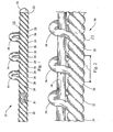
- FIGS. 1 and 2 depict a coupling wire guide 20 constructed in accordance with the teachings of the present invention.
- the coupling wire guide 20 includes a main body 22 having a distal portion 23.
- the main body 22, including the distal portion 23, is defined by a first wire 24, a second wire 26, and a third wire 28.
- the first, second and third wires 24, 26, 28 are disposed over a safety wire 21, which in turn is connected to an end cap 30 defining a distal tip 32 of the coupling wire guide 20.
- the first, second and third wires 24, 26, 28 are wound around the safety wire 21, preferably by coiling the wires in parallel to form three phases or filars. It can be seen in the figures that the wires 24, 26, 28 are immediately adjacent each other in the wind.
- the coupling wire guide 20 is structured for coupling to a previously introduced wire guide 10, depicted as a solid wire in FIG. 2 . While wire guides are often used in percutaneous interventional procedures, it will be recognized by those skilled in the art that the wire guides of the present invention may also be employed in endoscopic or other intracorporeal procedures. It will also be recognized that the previously introduced wire guide 10, as well as the main body 22 of the coupling wire guide 20, may take numerous forms as many types of wire guides are known in the art, including a solid wire, a tubular wire, a coiled wire and combinations thereof. For example, the previously introduced wire guide 10 may simply comprise a mandrel alone, or a combination of mandrel and coiled wire, as is shown in U.S. Patent No. 5,243,996 .
- At least the distal portion 23 preferably has a multiple filar construction, such as the coiled first, second and third wires 24, 26, 28 described above, although a single coiled wire may still employ the teachings of the present invention.
- the coupling wire guide 20 includes a first loop 34, a second loop 36, and a third loop 38.
- the loops 34, 36, 38 are each sized to receive a previously introduced wire guide 10 therein.
- Each loop 34, 36, 38 is formed in a similar manner, namely by way of an enlarged revolution of the respective first, second or third wire 24, 26, 28. That is, for each revolution of one of the wires 24, 26, 28, the wire spans an axial distance P, also referred to herein as the pitch.
- the loops 34, 36, 38 are axially spaced from one another such that the wind is progressed to maintain this pitch (i.e.
- the non-looping wires progress normally) in between each of the loops.
- the friction between the wires 24, 26, 28 assists in maintaining the position of the loops 34, 36, 38.
- the normal winding position of the second and third wires 26, 28 are maintained while the first wire 24 makes an enlarged revolution to define the first loop 34.
- the second wire 26 then makes its enlarged revolution to define the second loop 36, while the first and third wires 24, 28 continue on their normal progression.
- the first, second and third wires 24, 26, 28 may continue on their normal winding progression to define the remainder of the main body 22.
- the wire guides 10, 20 are coupled by placing a proximal end of the previously introduced wire guide 10 through each of the loops 34, 36, 38.
- the coupling wire guide 20 is then traversed through the vasculature in a normal manner, preferably while holding the previously introduced wire guide 10 in place.
- the wire guides 10, 20 are moved relative to one another such that a distal end of the previously introduced wire guide 10 passes proximally through and out of each of the loops 34, 36, 38.
- the main body 22 or at least its distal portion 23 may comprise a winding of only one or two wires, or may comprise a winding of more than three wires. It will also be recognized that a loop does not need to be formed in each of the wires.
- distal portion 23 may comprise a winding of three wires with single or multiple loops formed in only one or two of the wires.
- one set of loops 34, 36, 38 have been depicted, it will be recognized that additional sets of loops may be readily formed.
- a wire guide having a single coiled wire may include one or more loops
- a wire guide having two or more wires may include one or more loops in one or more of the wires.
- the medical professional is provided with flexibility in the manner of coupling two wire guides 10, 20.
- less than all of the loops 34, 36, 38 may be used to couple the wire guides 10, 20, resulting in different levels of coupling support.
- Additional flexibility is provided since the loops 34, 36, 38 may be formed at any axial position along the length of the coupling wire guide 20, although it is preferred that the loops are formed in a distal portion 23 of the wire guide 20 and adjacent the distal tip 32 thereof, thereby facilitating decoupling of the two wire guides 10, 20 inside the vasculature with minimal relative translation of the two wire guides 10, 20.
- the size of the loops 34, 36, 38 may be of any area or diameter, and preferably are sized such that the loops may receive numerous sizes of previously introduced wire guides 10 having a range of sizes (diameters).
- the wires 24, 26, 28 are preferably formed of a metal or alloy such as stainless steel or Nitinol (Ni-Ti) although any known or future developed wire guide materials may be used, and thus the loops 34, 36, 38 are flexible and may bend or fold to a position close to the wire guide 20. In this manner the distal portion 23 is provided with an extremely low profile that is not significantly greater in size than a standard wire guide. An even lower profile, and specifically a normal configuration of the wire guide 20, may also be achieved through a particular construction of the wire guide 20. That is, the loops 34, 36, 38 may be selectively "removed" from the wire guide 20 through simple manipulation of the wire guide 20, as will be described below.
- a metal or alloy such as stainless steel or Nitinol (Ni-Ti) although any known or future developed wire guide materials may be used, and thus the loops 34, 36, 38 are flexible and may bend or fold to a position close to the wire guide 20. In this manner the distal portion 23 is provided with an extremely low profile
- One method of forming the coupling wire guide 20 described above, as well as removing the loops 34, 36, 38, is through the manipulation of a standard mutlifilar wire guide.
- the twisted wire portion of the wire guide may be clamped at a clamping point proximal to the distal end of the wire guide, such as by pinching the wire guide with one's fingers.
- the clamping point may include the proximal end of the wire guide.
- the wire guide is backtwisted (i.e. a portion distal to the clamping point is rotated counter to the winding direction) to loosen the winding of the wires 24, 26, 28.
- Each of the wires 24, 26, 28 are then grasped and pulled to form an enlarged revolution, i.e. a loop 34, 36, 38.
- these loops 34, 36, 38 are positioned and spaced in the manner described above.
- the portion of the wire guide 20 distal to the loops 34, 36, 38 are twisted again in their normal manner to re-form the wire guide 20.
- the method of forming the wire guide 20 described in the preceding paragraph may be reversed once the loops 34, 36, 38 have been formed, whereby the loops 34, 36, 38 may be removed through backtwisting and then proper re-twisting of the wires 24, 26, 28. It will also be recognized that this process may be repeated indefinitely to form more loops, to remove loops, or to shift the position of loops. In fact, the location of the loops 34, 36, 38 may be shifted with little to no backtwisting through simple manipulation of the wires 24, 26, 28 in the area of the loops 34, 36, 38.
- the coupling wire guide by way of formed loops 34, 36, 38, provides a simple and reliable connection to a previously introduced wire guide 10.
- the loops 34, 36, 38 provide an extremely secure interconnection of the wire guides 10, 20, and are sized to provide easy connection between coupling wire guide 20 and various sized wire guides 10.
- the loops 34, 36, 38 are sufficiently flexible to provide a low profile for the coupling wire guide 20, and additionally may be easily removed or shifted in position depending on the needs of the user.
- the atraumatic nature of the distal tip 32 is maintained, as is the preferred balance between flexibility and rigidity of the main body 22. In this manner, the coupling wire guide 20 is increasingly adept at traversing the vasculature, and in particular torturous pathways, while at the same time having sufficient rigidity for straightening out these passageways and passing through occlusions or other obstacles.
Landscapes
- Health & Medical Sciences (AREA)
- Life Sciences & Earth Sciences (AREA)
- Hematology (AREA)
- Animal Behavior & Ethology (AREA)
- Engineering & Computer Science (AREA)
- Anesthesiology (AREA)
- Biomedical Technology (AREA)
- Heart & Thoracic Surgery (AREA)
- Biophysics (AREA)
- Pulmonology (AREA)
- General Health & Medical Sciences (AREA)
- Public Health (AREA)
- Veterinary Medicine (AREA)
- Media Introduction/Drainage Providing Device (AREA)
- Endoscopes (AREA)
- Ropes Or Cables (AREA)
Applications Claiming Priority (2)
| Application Number | Priority Date | Filing Date | Title |
|---|---|---|---|
| US73077605P | 2005-10-27 | 2005-10-27 | |
| PCT/US2006/042184 WO2007050977A2 (en) | 2005-10-27 | 2006-10-26 | Wire guide having distal coupling tip |
Publications (2)
| Publication Number | Publication Date |
|---|---|
| EP1951351A2 EP1951351A2 (en) | 2008-08-06 |
| EP1951351B1 true EP1951351B1 (en) | 2009-09-30 |
Family
ID=37682873
Family Applications (1)
| Application Number | Title | Priority Date | Filing Date |
|---|---|---|---|
| EP06826986A Not-in-force EP1951351B1 (en) | 2005-10-27 | 2006-10-26 | Wire guide having distal coupling tip |
Country Status (6)
| Country | Link |
|---|---|
| US (1) | US8137291B2 (enExample) |
| EP (1) | EP1951351B1 (enExample) |
| JP (1) | JP5022374B2 (enExample) |
| AT (1) | ATE444095T1 (enExample) |
| DE (1) | DE602006009546D1 (enExample) |
| WO (1) | WO2007050977A2 (enExample) |
Families Citing this family (11)
| Publication number | Priority date | Publication date | Assignee | Title |
|---|---|---|---|---|
| US9220523B2 (en) | 2009-09-14 | 2015-12-29 | The Spectranetics Corporation | Snaring systems and methods |
| US9498356B2 (en) | 2012-12-19 | 2016-11-22 | Cook Medical Technologies, LLC | Flexible stent and delivery system |
| CN105307601B (zh) * | 2013-03-14 | 2019-01-29 | 火山公司 | 辅助小血管系统导引线 |
| US9763814B2 (en) | 2014-10-24 | 2017-09-19 | Cook Medical Technologies Llc | Elongate medical device |
| US9884184B2 (en) | 2014-12-30 | 2018-02-06 | The Spectranetics Corporation | Wire hook coupling for lead extension and extraction |
| US10105533B2 (en) | 2014-12-30 | 2018-10-23 | The Spectranetics Corporation | Multi-loop coupling for lead extension and extraction |
| US9731113B2 (en) | 2014-12-30 | 2017-08-15 | The Spectranetics Corporation | Collapsing coil coupling for lead extension and extraction |
| US10576274B2 (en) | 2014-12-30 | 2020-03-03 | Spectranetics Llc | Expanding coil coupling for lead extension and extraction |
| US20200114129A1 (en) * | 2018-02-26 | 2020-04-16 | Horizon Patents, LLC | Guidewire for catheter insertion |
| WO2020019310A1 (zh) * | 2018-07-27 | 2020-01-30 | 尚华 | 一种血管内记忆金属穿刺系统及其应用方法 |
| US12178974B2 (en) | 2021-01-21 | 2024-12-31 | Abbott Cardiovascular Systems Inc. | Guidewire and method of use |
Family Cites Families (122)
| Publication number | Priority date | Publication date | Assignee | Title |
|---|---|---|---|---|
| US892472A (en) * | 1908-02-28 | 1908-07-07 | Sadie M Walker | Gape-worm extractor. |
| US2657691A (en) | 1952-12-01 | 1953-11-03 | Jr Nils Nordstrom | Instrument useful in anesthetizing by intratracheal insufflation |
| US3547103A (en) | 1965-10-29 | 1970-12-15 | William A Cook | Coil spring guide |
| US3521620A (en) * | 1967-10-30 | 1970-07-28 | William A Cook | Vascular coil spring guide with bendable tip |
| US3656680A (en) * | 1970-03-20 | 1972-04-18 | Nippon Kokan Kk | Apparatus for simultaneously welding pairs of reinforcing plates to a base plate |
| US3739784A (en) * | 1971-12-01 | 1973-06-19 | Olympus Optical Co | Surgical instrument |
| DE2210362C3 (de) * | 1972-03-03 | 1980-10-09 | Linde Ag, 6200 Wiesbaden | Selbsttätiges Druckregelventil |
| US3890977A (en) | 1974-03-01 | 1975-06-24 | Bruce C Wilson | Kinetic memory electrodes, catheters and cannulae |
| US4548206A (en) * | 1983-07-21 | 1985-10-22 | Cook, Incorporated | Catheter wire guide with movable mandril |
| CA1232814A (en) * | 1983-09-16 | 1988-02-16 | Hidetoshi Sakamoto | Guide wire for catheter |
| US4665906A (en) * | 1983-10-14 | 1987-05-19 | Raychem Corporation | Medical devices incorporating sim alloy elements |
| US5190546A (en) * | 1983-10-14 | 1993-03-02 | Raychem Corporation | Medical devices incorporating SIM alloy elements |
| US4569347A (en) * | 1984-05-30 | 1986-02-11 | Advanced Cardiovascular Systems, Inc. | Catheter introducing device, assembly and method |
| US4601713A (en) * | 1985-06-11 | 1986-07-22 | Genus Catheter Technologies, Inc. | Variable diameter catheter |
| US4650472A (en) * | 1985-08-30 | 1987-03-17 | Cook, Incorporated | Apparatus and method for effecting percutaneous catheterization of a blood vessel using a small gauge introducer needle |
| US4921483A (en) * | 1985-12-19 | 1990-05-01 | Leocor, Inc. | Angioplasty catheter |
| US5046497A (en) * | 1986-11-14 | 1991-09-10 | Millar Instruments, Inc. | Structure for coupling a guidewire and a catheter |
| US5105818A (en) * | 1987-04-10 | 1992-04-21 | Cardiometric, Inc. | Apparatus, system and method for measuring spatial average velocity and/or volumetric flow of blood in a vessel and screw joint for use therewith |
| US4824435A (en) * | 1987-05-18 | 1989-04-25 | Thomas J. Fogarty | Instrument guidance system |
| US4934380A (en) * | 1987-11-27 | 1990-06-19 | Boston Scientific Corporation | Medical guidewire |
| DE3825631A1 (de) * | 1988-07-28 | 1990-02-08 | Osypka Peter | Vorrichtung zum transvenoesen oder arteriellen einfuehren mittels eines fuehrungsdrahtes |
| US4984581A (en) * | 1988-10-12 | 1991-01-15 | Flexmedics Corporation | Flexible guide having two-way shape memory alloy |
| EP0395098B1 (en) | 1989-04-28 | 1994-04-06 | Tokin Corporation | Readily operable catheter guide wire using shape memory alloy with pseudo elasticity |
| CA2019063E (en) * | 1989-06-29 | 2000-01-04 | Brian L. Bates | Hydrophilically coated flexible wire guide |
| EP0436303A1 (en) | 1989-12-01 | 1991-07-10 | C.R. Bard, Inc. | Guidewire with member for tracking along an indwelling device, and catheter exchange system |
| US5131407A (en) * | 1989-12-01 | 1992-07-21 | C. R. Bard, Inc. | Guidewire with tracking member and catheter exchange system |
| US6682608B2 (en) * | 1990-12-18 | 2004-01-27 | Advanced Cardiovascular Systems, Inc. | Superelastic guiding member |
| US6165292A (en) | 1990-12-18 | 2000-12-26 | Advanced Cardiovascular Systems, Inc. | Superelastic guiding member |
| US5354257A (en) * | 1991-01-29 | 1994-10-11 | Med Institute, Inc. | Minimally invasive medical device for providing a radiation treatment |
| US5242759A (en) * | 1991-05-21 | 1993-09-07 | Cook Incorporated | Joint, a laminate, and a method of preparing a nickel-titanium alloy member surface for bonding to another layer of metal |
| US5344413A (en) * | 1991-06-28 | 1994-09-06 | C. R. Bard, Inc. | Catheter having a tip connector for rapid catheter exchanges |
| US5213111A (en) * | 1991-07-10 | 1993-05-25 | Cook Incorporated | Composite wire guide construction |
| CA2114222A1 (en) * | 1991-08-28 | 1993-03-18 | Kenneth R. Brennen | Steerable stylet and manipulative handle assembly |
| US5159861A (en) | 1991-09-27 | 1992-11-03 | Cook Incorporated | Wire guide control handle |
| US5325746A (en) * | 1991-09-27 | 1994-07-05 | Cook Incorporated | Wire guide control handle |
| US5449362A (en) * | 1991-12-19 | 1995-09-12 | Chaisson; Gary A. | Guiding catheter exchange device |
| US5243996A (en) * | 1992-01-03 | 1993-09-14 | Cook, Incorporated | Small-diameter superelastic wire guide |
| US5234003A (en) * | 1992-02-20 | 1993-08-10 | Cook Incorporated | Flexible tip wire guide |
| US5413560A (en) * | 1992-03-30 | 1995-05-09 | Pameda N.V. | Method of rapid catheter exchange |
| US5267958A (en) | 1992-03-30 | 1993-12-07 | Medtronic, Inc. | Exchange catheter having exterior guide wire loops |
| US5251640A (en) * | 1992-03-31 | 1993-10-12 | Cook, Incorporated | Composite wire guide shaft |
| US5328472A (en) * | 1992-07-27 | 1994-07-12 | Medtronic, Inc. | Catheter with flexible side port entry |
| US5257974A (en) * | 1992-08-19 | 1993-11-02 | Scimed Life Systems, Inc. | Performance enhancement adaptor for intravascular balloon catheter |
| US5328480A (en) * | 1992-10-09 | 1994-07-12 | Cook Incorporated | Vascular wire guiode introducer and method of use |
| US5383853A (en) * | 1992-11-12 | 1995-01-24 | Medtronic, Inc. | Rapid exchange catheter |
| US5318527A (en) * | 1992-12-22 | 1994-06-07 | Advanced Cardiovascular Systems, Inc. | Fixed wire catheter exchange device |
| US5527326A (en) * | 1992-12-29 | 1996-06-18 | Thomas J. Fogarty | Vessel deposit shearing apparatus |
| US5306261A (en) * | 1993-01-22 | 1994-04-26 | Misonix, Inc. | Catheter with collapsible wire guide |
| US5402799A (en) * | 1993-06-29 | 1995-04-04 | Cordis Corporation | Guidewire having flexible floppy tip |
| US5456680A (en) * | 1993-09-14 | 1995-10-10 | Spectranetics Corp | Fiber optic catheter with shortened guide wire lumen |
| JPH0737199U (ja) * | 1993-12-24 | 1995-07-11 | テルモ株式会社 | ガイドワイヤー |
| US5488959A (en) * | 1993-12-27 | 1996-02-06 | Cordis Corporation | Medical guidewire and welding process |
| US6139510A (en) * | 1994-05-11 | 2000-10-31 | Target Therapeutics Inc. | Super elastic alloy guidewire |
| US5882333A (en) * | 1994-05-13 | 1999-03-16 | Cardima, Inc. | Catheter with deflectable distal section |
| WO1996000099A1 (en) * | 1994-06-24 | 1996-01-04 | Advanced Cardiovascular Systems Inc. | Catheters having a reusable proximal body |
| AU3498295A (en) * | 1994-09-26 | 1996-04-19 | Medtronic, Inc. | Cathether flexible distal tip |
| US6348056B1 (en) * | 1999-08-06 | 2002-02-19 | Scimed Life Systems, Inc. | Medical retrieval device with releasable retrieval basket |
| US5762070A (en) * | 1995-04-28 | 1998-06-09 | Olympus Optical Co., Ltd. | Treatment tool for endoscope, having openable and closable treatment members and guide means therefore |
| US5776100A (en) * | 1995-09-27 | 1998-07-07 | Interventional Innovations Corporation | Nickel titanium guide wires for occlusion and drug delivery |
| US5810876A (en) * | 1995-10-03 | 1998-09-22 | Akos Biomedical, Inc. | Flexible forceps device |
| US5891056A (en) * | 1996-03-15 | 1999-04-06 | Advanced Cardiovascular Systems, Inc. | Guidewire replacement device with flexible intermediate section |
| US5997526A (en) | 1996-03-25 | 1999-12-07 | The Uab Research Foundation | Shape memory catheter |
| US6068623A (en) * | 1997-03-06 | 2000-05-30 | Percusurge, Inc. | Hollow medical wires and methods of constructing same |
| US5993424A (en) | 1996-08-05 | 1999-11-30 | Cordis Corporation | Guidewire having a distal tip that can change its shape within a vessel |
| US5776079A (en) * | 1996-08-06 | 1998-07-07 | Cook Incorporated | Retrograde-antegrade catheterization guide wire |
| US6007517A (en) | 1996-08-19 | 1999-12-28 | Anderson; R. David | Rapid exchange/perfusion angioplasty catheter |
| EP0829269A1 (en) | 1996-09-11 | 1998-03-18 | Schneider (Europe) Ag | Catheter system |
| US6606515B1 (en) * | 1996-09-13 | 2003-08-12 | Scimed Life Systems, Inc. | Guide wire insertion and re-insertion tools and methods of use |
| US5893868A (en) * | 1997-03-05 | 1999-04-13 | Scimed Life Systems, Inc. | Catheter with removable balloon protector and stent delivery system with removable stent protector |
| US6309339B1 (en) * | 1997-03-28 | 2001-10-30 | Endosonics Corporation | Intravascular radiation delivery device |
| US5971983A (en) | 1997-05-09 | 1999-10-26 | The Regents Of The University Of California | Tissue ablation device and method of use |
| US6132388A (en) | 1997-10-16 | 2000-10-17 | Scimed Life Systems, Inc. | Guide wire tip |
| JP2002523152A (ja) * | 1998-08-19 | 2002-07-30 | クック インコーポレイティド | 予備成形ワイヤ・ガイド |
| JP3684085B2 (ja) * | 1998-09-02 | 2005-08-17 | ペンタックス株式会社 | 内視鏡用ワイヤループ型処置具 |
| US6221066B1 (en) * | 1999-03-09 | 2001-04-24 | Micrus Corporation | Shape memory segmented detachable coil |
| ATE266442T1 (de) * | 1999-03-29 | 2004-05-15 | Cook William Europ | Ein führungsdraht |
| DK1040843T3 (da) * | 1999-03-29 | 2006-01-30 | William Cook Europe As | En guidewire |
| EP1057500A1 (en) | 1999-06-04 | 2000-12-06 | Radi Medical Technologies AB | Driving unit for intravascular radiation therapy |
| EP1185200B1 (en) * | 1999-06-05 | 2008-01-09 | Wilson-Cook Medical Inc. | Indicia for an endoscopic medical device |
| US6348045B1 (en) * | 1999-07-12 | 2002-02-19 | Impulse Dynamics N.V. | Catheter with distal-end engaging means |
| US6309404B1 (en) * | 1999-10-19 | 2001-10-30 | Jacek Krzyzanowski | Flexible biopsy jaw assembly |
| US6451026B1 (en) * | 1999-12-21 | 2002-09-17 | Advanced Cardiovascular Systems, Inc. | Dock exchange system for composite guidewires |
| US20050075647A1 (en) * | 2000-03-10 | 2005-04-07 | Greg Walters | Tool for facilitating the connecting of a catheter or other tubular member onto a guide-wire without access to the ends of the guide-wire |
| US6517518B2 (en) * | 2000-03-10 | 2003-02-11 | Kensey Nash Corporation | Tool for facilitating the connecting of a catheter or other tubular member onto a guide-wire without access to the ends of the guide-wire |
| US6569151B1 (en) * | 2000-03-10 | 2003-05-27 | Kensey Nash Corporation | Device for connecting a catheter or other tubular member onto a guide-wire without access to the ends of the guide-wire |
| US6530899B1 (en) * | 2000-03-27 | 2003-03-11 | Jomed Inc. | Catheter having a spear shaped tip |
| US20050283122A1 (en) | 2000-04-03 | 2005-12-22 | Greg Nordgren | Slit valves bridging between the tip and distal side wall of catheter tubes and methods |
| AU2001263284A1 (en) * | 2000-05-17 | 2001-11-26 | Cook Vascular Incorporated | Lead removal apparatus |
| ATE287747T1 (de) | 2000-10-03 | 2005-02-15 | Cook William Europ | Führungsdraht |
| WO2002038211A1 (en) * | 2000-11-09 | 2002-05-16 | Kaneka Corporation | Medical balloon catheter |
| US6605049B1 (en) * | 2000-12-21 | 2003-08-12 | Advanced Cardiovascular Systems, Inc. | Marking system and method for medical devices |
| US6500130B2 (en) | 2000-12-21 | 2002-12-31 | Scimed Life Systems, Inc. | Steerable guidewire |
| WO2002083009A1 (fr) * | 2001-04-12 | 2002-10-24 | Olympus Optical Co., Ltd. | Outil de traitement pour endoscope |
| US6942653B2 (en) | 2001-05-11 | 2005-09-13 | Radius International Limited Partnership | Blood vessel catheter |
| US6749628B1 (en) | 2001-05-17 | 2004-06-15 | Advanced Cardiovascular Systems, Inc. | Stent and catheter assembly and method for treating bifurcations |
| US6911016B2 (en) * | 2001-08-06 | 2005-06-28 | Scimed Life Systems, Inc. | Guidewire extension system |
| US6596963B2 (en) * | 2001-08-31 | 2003-07-22 | General Electric Company | Production and use of welding filler metal |
| US6918882B2 (en) * | 2001-10-05 | 2005-07-19 | Scimed Life Systems, Inc. | Guidewire with stiffness blending connection |
| WO2003039626A2 (en) * | 2001-11-08 | 2003-05-15 | Houser Russell A | Rapid exchange catheter with stent deployment, therapeutic infusion, and lesion sampling features |
| WO2003101524A1 (en) * | 2002-05-29 | 2003-12-11 | Wilson-Cook Medical Inc. | Device for directing a wire guide |
| DE60331328D1 (de) | 2002-10-04 | 2010-04-01 | Advanced Cardiovascular System | Strahlungsundurchlässige nitinollegierungen für medizinische geräte |
| US7758592B2 (en) * | 2002-12-02 | 2010-07-20 | Wilson-Cook Medical Inc. | Loop tip wire guide |
| AU2003294467A1 (en) | 2002-12-02 | 2004-06-23 | William Cook Europe Aps | Loop tip wire guide |
| WO2004049970A2 (en) * | 2002-12-04 | 2004-06-17 | Lake Region Manufacturing, Inc. | Marked guidewires |
| US6824543B2 (en) | 2002-12-11 | 2004-11-30 | Cryocor, Inc. | Guidance system for a cryocatheter |
| GB0307715D0 (en) | 2003-04-03 | 2003-05-07 | Ethicon Endo Surgery Inc | Guide wire structure for insertion into an internal space |
| US8211087B2 (en) * | 2003-07-31 | 2012-07-03 | Cook Medical Technologies Llc | Distal wire stop |
| JP4611301B2 (ja) | 2003-07-31 | 2011-01-12 | ウィルソン−クック・メディカル・インコーポレーテッド | 複数の医療装置を導入するためのシステム及び方法 |
| US7951091B2 (en) * | 2003-07-31 | 2011-05-31 | Tyco Healthcare Group Lp | Guide wire with stranded tip |
| WO2005025660A1 (en) | 2003-09-05 | 2005-03-24 | Cook Urological, Incorporated | Double ended wire guide |
| ATE475446T1 (de) * | 2004-03-01 | 2010-08-15 | Terumo Corp | Vorrichtung zur einführung eines länglichen gegenstandes |
| AU2005222642B2 (en) | 2004-03-17 | 2010-11-04 | Cook Medical Technologies Llc | Second wire apparatus and installation procedure |
| WO2005118045A1 (en) * | 2004-05-27 | 2005-12-15 | Abbott Laboratories | Catheter having main body portion with coil-defined guidewire passage |
| US7850675B2 (en) * | 2004-07-20 | 2010-12-14 | Boston Scientific Scimed, Inc. | Reinforced venous access catheter |
| EP1804885B1 (en) * | 2004-09-30 | 2009-01-07 | Wilson-Cook Medical Inc. | Steerable loop tip wire-guide |
| US7705701B2 (en) * | 2005-07-15 | 2010-04-27 | General Electric Company | Thin metal layer vacuum vessels with composite structural support |
| US7938820B2 (en) * | 2005-08-18 | 2011-05-10 | Lumen Biomedical, Inc. | Thrombectomy catheter |
| US9005138B2 (en) * | 2005-08-25 | 2015-04-14 | Cook Medical Technologies Llc | Wire guide having distal coupling tip |
| US20070149946A1 (en) | 2005-12-07 | 2007-06-28 | Viswanathan Raju R | Advancer system for coaxial medical devices |
| US7811238B2 (en) | 2006-01-13 | 2010-10-12 | Cook Incorporated | Wire guide having distal coupling tip |
| US7785275B2 (en) | 2006-01-31 | 2010-08-31 | Cook Incorporated | Wire guide having distal coupling tip |
| US20070191790A1 (en) * | 2006-02-16 | 2007-08-16 | Cook Incorporated | Wire guide having distal coupling tip |
-
2006
- 2006-10-13 US US11/549,466 patent/US8137291B2/en not_active Expired - Fee Related
- 2006-10-26 AT AT06826986T patent/ATE444095T1/de not_active IP Right Cessation
- 2006-10-26 EP EP06826986A patent/EP1951351B1/en not_active Not-in-force
- 2006-10-26 WO PCT/US2006/042184 patent/WO2007050977A2/en not_active Ceased
- 2006-10-26 JP JP2008538052A patent/JP5022374B2/ja not_active Expired - Fee Related
- 2006-10-26 DE DE602006009546T patent/DE602006009546D1/de active Active
Also Published As
| Publication number | Publication date |
|---|---|
| JP2009513271A (ja) | 2009-04-02 |
| US8137291B2 (en) | 2012-03-20 |
| ATE444095T1 (de) | 2009-10-15 |
| WO2007050977A3 (en) | 2007-07-05 |
| JP5022374B2 (ja) | 2012-09-12 |
| DE602006009546D1 (enExample) | 2009-11-12 |
| US20070118052A1 (en) | 2007-05-24 |
| WO2007050977A2 (en) | 2007-05-03 |
| EP1951351A2 (en) | 2008-08-06 |
Similar Documents
| Publication | Publication Date | Title |
|---|---|---|
| EP1979037B1 (en) | Wire guide having distal coupling tip for attachement to a previously introduced wire guide | |
| EP1948283B1 (en) | Coupling wire guide | |
| US7785275B2 (en) | Wire guide having distal coupling tip | |
| US8043232B2 (en) | High performance wire guide | |
| JP4600876B2 (ja) | ガイドワイヤ | |
| US6139540A (en) | Guidewire with disposition to coil | |
| US8696599B2 (en) | Medical systems, devices and methods for coupling wire guides | |
| EP0556316B1 (en) | Guidewire for crossing occlusions in blood vessels | |
| EP0823261B1 (en) | Guidewire having a distal tip that can change its shape within a vessel | |
| EP1976587B1 (en) | Wire guide having distal coupling tip | |
| EP1951351B1 (en) | Wire guide having distal coupling tip | |
| HK1243663A1 (zh) | 血管再进入导管 | |
| US7682365B2 (en) | Catheter device for support of a guidewire in crossing a lesion | |
| US20070191790A1 (en) | Wire guide having distal coupling tip | |
| US20090312670A1 (en) | Wire guide having a rib for coil attachment | |
| US8075497B2 (en) | Wire guide having distal coupling tip | |
| CN114668955A (zh) | 导丝 | |
| WO2021222443A1 (en) | Coil wire for navigation in vascular tortuosity and methods of using the coil wire | |
| WO2008105756A1 (en) | Wire guide having distal coupling tip |
Legal Events
| Date | Code | Title | Description |
|---|---|---|---|
| PUAI | Public reference made under article 153(3) epc to a published international application that has entered the european phase |
Free format text: ORIGINAL CODE: 0009012 |
|
| 17P | Request for examination filed |
Effective date: 20080430 |
|
| AK | Designated contracting states |
Kind code of ref document: A2 Designated state(s): AT BE BG CH CY CZ DE DK EE ES FI FR GB GR HU IE IS IT LI LT LU LV MC NL PL PT RO SE SI SK TR |
|
| GRAP | Despatch of communication of intention to grant a patent |
Free format text: ORIGINAL CODE: EPIDOSNIGR1 |
|
| GRAS | Grant fee paid |
Free format text: ORIGINAL CODE: EPIDOSNIGR3 |
|
| GRAA | (expected) grant |
Free format text: ORIGINAL CODE: 0009210 |
|
| AK | Designated contracting states |
Kind code of ref document: B1 Designated state(s): AT BE BG CH CY CZ DE DK EE ES FI FR GB GR HU IE IS IT LI LT LU LV MC NL PL PT RO SE SI SK TR |
|
| REG | Reference to a national code |
Ref country code: CH Ref legal event code: EP Ref country code: GB Ref legal event code: FG4D |
|
| REG | Reference to a national code |
Ref country code: IE Ref legal event code: FG4D |
|
| REF | Corresponds to: |
Ref document number: 602006009546 Country of ref document: DE Date of ref document: 20091112 Kind code of ref document: P |
|
| PG25 | Lapsed in a contracting state [announced via postgrant information from national office to epo] |
Ref country code: LT Free format text: LAPSE BECAUSE OF FAILURE TO SUBMIT A TRANSLATION OF THE DESCRIPTION OR TO PAY THE FEE WITHIN THE PRESCRIBED TIME-LIMIT Effective date: 20090930 Ref country code: SE Free format text: LAPSE BECAUSE OF FAILURE TO SUBMIT A TRANSLATION OF THE DESCRIPTION OR TO PAY THE FEE WITHIN THE PRESCRIBED TIME-LIMIT Effective date: 20090930 Ref country code: FI Free format text: LAPSE BECAUSE OF FAILURE TO SUBMIT A TRANSLATION OF THE DESCRIPTION OR TO PAY THE FEE WITHIN THE PRESCRIBED TIME-LIMIT Effective date: 20090930 |
|
| LTIE | Lt: invalidation of european patent or patent extension |
Effective date: 20090930 |
|
| PG25 | Lapsed in a contracting state [announced via postgrant information from national office to epo] |
Ref country code: PL Free format text: LAPSE BECAUSE OF FAILURE TO SUBMIT A TRANSLATION OF THE DESCRIPTION OR TO PAY THE FEE WITHIN THE PRESCRIBED TIME-LIMIT Effective date: 20090930 Ref country code: SI Free format text: LAPSE BECAUSE OF FAILURE TO SUBMIT A TRANSLATION OF THE DESCRIPTION OR TO PAY THE FEE WITHIN THE PRESCRIBED TIME-LIMIT Effective date: 20090930 Ref country code: LV Free format text: LAPSE BECAUSE OF FAILURE TO SUBMIT A TRANSLATION OF THE DESCRIPTION OR TO PAY THE FEE WITHIN THE PRESCRIBED TIME-LIMIT Effective date: 20090930 |
|
| NLV1 | Nl: lapsed or annulled due to failure to fulfill the requirements of art. 29p and 29m of the patents act | ||
| PG25 | Lapsed in a contracting state [announced via postgrant information from national office to epo] |
Ref country code: IS Free format text: LAPSE BECAUSE OF FAILURE TO SUBMIT A TRANSLATION OF THE DESCRIPTION OR TO PAY THE FEE WITHIN THE PRESCRIBED TIME-LIMIT Effective date: 20100130 Ref country code: CZ Free format text: LAPSE BECAUSE OF FAILURE TO SUBMIT A TRANSLATION OF THE DESCRIPTION OR TO PAY THE FEE WITHIN THE PRESCRIBED TIME-LIMIT Effective date: 20090930 Ref country code: RO Free format text: LAPSE BECAUSE OF FAILURE TO SUBMIT A TRANSLATION OF THE DESCRIPTION OR TO PAY THE FEE WITHIN THE PRESCRIBED TIME-LIMIT Effective date: 20090930 Ref country code: EE Free format text: LAPSE BECAUSE OF FAILURE TO SUBMIT A TRANSLATION OF THE DESCRIPTION OR TO PAY THE FEE WITHIN THE PRESCRIBED TIME-LIMIT Effective date: 20090930 Ref country code: ES Free format text: LAPSE BECAUSE OF FAILURE TO SUBMIT A TRANSLATION OF THE DESCRIPTION OR TO PAY THE FEE WITHIN THE PRESCRIBED TIME-LIMIT Effective date: 20100110 Ref country code: PT Free format text: LAPSE BECAUSE OF FAILURE TO SUBMIT A TRANSLATION OF THE DESCRIPTION OR TO PAY THE FEE WITHIN THE PRESCRIBED TIME-LIMIT Effective date: 20100201 |
|
| PG25 | Lapsed in a contracting state [announced via postgrant information from national office to epo] |
Ref country code: SK Free format text: LAPSE BECAUSE OF FAILURE TO SUBMIT A TRANSLATION OF THE DESCRIPTION OR TO PAY THE FEE WITHIN THE PRESCRIBED TIME-LIMIT Effective date: 20090930 Ref country code: MC Free format text: LAPSE BECAUSE OF NON-PAYMENT OF DUE FEES Effective date: 20091031 |
|
| PG25 | Lapsed in a contracting state [announced via postgrant information from national office to epo] |
Ref country code: AT Free format text: LAPSE BECAUSE OF FAILURE TO SUBMIT A TRANSLATION OF THE DESCRIPTION OR TO PAY THE FEE WITHIN THE PRESCRIBED TIME-LIMIT Effective date: 20090930 Ref country code: BE Free format text: LAPSE BECAUSE OF FAILURE TO SUBMIT A TRANSLATION OF THE DESCRIPTION OR TO PAY THE FEE WITHIN THE PRESCRIBED TIME-LIMIT Effective date: 20090930 |
|
| PG25 | Lapsed in a contracting state [announced via postgrant information from national office to epo] |
Ref country code: NL Free format text: LAPSE BECAUSE OF FAILURE TO SUBMIT A TRANSLATION OF THE DESCRIPTION OR TO PAY THE FEE WITHIN THE PRESCRIBED TIME-LIMIT Effective date: 20090930 Ref country code: DK Free format text: LAPSE BECAUSE OF FAILURE TO SUBMIT A TRANSLATION OF THE DESCRIPTION OR TO PAY THE FEE WITHIN THE PRESCRIBED TIME-LIMIT Effective date: 20090930 |
|
| PLBE | No opposition filed within time limit |
Free format text: ORIGINAL CODE: 0009261 |
|
| STAA | Information on the status of an ep patent application or granted ep patent |
Free format text: STATUS: NO OPPOSITION FILED WITHIN TIME LIMIT |
|
| 26N | No opposition filed |
Effective date: 20100701 |
|
| PG25 | Lapsed in a contracting state [announced via postgrant information from national office to epo] |
Ref country code: GR Free format text: LAPSE BECAUSE OF FAILURE TO SUBMIT A TRANSLATION OF THE DESCRIPTION OR TO PAY THE FEE WITHIN THE PRESCRIBED TIME-LIMIT Effective date: 20091231 |
|
| PG25 | Lapsed in a contracting state [announced via postgrant information from national office to epo] |
Ref country code: IT Free format text: LAPSE BECAUSE OF FAILURE TO SUBMIT A TRANSLATION OF THE DESCRIPTION OR TO PAY THE FEE WITHIN THE PRESCRIBED TIME-LIMIT Effective date: 20090930 Ref country code: BG Free format text: LAPSE BECAUSE OF FAILURE TO SUBMIT A TRANSLATION OF THE DESCRIPTION OR TO PAY THE FEE WITHIN THE PRESCRIBED TIME-LIMIT Effective date: 20091031 |
|
| PG25 | Lapsed in a contracting state [announced via postgrant information from national office to epo] |
Ref country code: LU Free format text: LAPSE BECAUSE OF NON-PAYMENT OF DUE FEES Effective date: 20091026 |
|
| REG | Reference to a national code |
Ref country code: CH Ref legal event code: PL |
|
| REG | Reference to a national code |
Ref country code: FR Ref legal event code: ST Effective date: 20110502 |
|
| PG25 | Lapsed in a contracting state [announced via postgrant information from national office to epo] |
Ref country code: HU Free format text: LAPSE BECAUSE OF FAILURE TO SUBMIT A TRANSLATION OF THE DESCRIPTION OR TO PAY THE FEE WITHIN THE PRESCRIBED TIME-LIMIT Effective date: 20100401 |
|
| PG25 | Lapsed in a contracting state [announced via postgrant information from national office to epo] |
Ref country code: CH Free format text: LAPSE BECAUSE OF NON-PAYMENT OF DUE FEES Effective date: 20101031 Ref country code: FR Free format text: LAPSE BECAUSE OF NON-PAYMENT OF DUE FEES Effective date: 20091130 Ref country code: LI Free format text: LAPSE BECAUSE OF NON-PAYMENT OF DUE FEES Effective date: 20101031 |
|
| PG25 | Lapsed in a contracting state [announced via postgrant information from national office to epo] |
Ref country code: TR Free format text: LAPSE BECAUSE OF FAILURE TO SUBMIT A TRANSLATION OF THE DESCRIPTION OR TO PAY THE FEE WITHIN THE PRESCRIBED TIME-LIMIT Effective date: 20090930 |
|
| REG | Reference to a national code |
Ref country code: GB Ref legal event code: 732E Free format text: REGISTERED BETWEEN 20110804 AND 20110810 |
|
| PG25 | Lapsed in a contracting state [announced via postgrant information from national office to epo] |
Ref country code: CY Free format text: LAPSE BECAUSE OF FAILURE TO SUBMIT A TRANSLATION OF THE DESCRIPTION OR TO PAY THE FEE WITHIN THE PRESCRIBED TIME-LIMIT Effective date: 20090930 |
|
| PGFP | Annual fee paid to national office [announced via postgrant information from national office to epo] |
Ref country code: IE Payment date: 20220926 Year of fee payment: 17 Ref country code: GB Payment date: 20220914 Year of fee payment: 17 |
|
| PGFP | Annual fee paid to national office [announced via postgrant information from national office to epo] |
Ref country code: DE Payment date: 20220914 Year of fee payment: 17 |
|
| P01 | Opt-out of the competence of the unified patent court (upc) registered |
Effective date: 20230602 |
|
| REG | Reference to a national code |
Ref country code: DE Ref legal event code: R119 Ref document number: 602006009546 Country of ref document: DE |
|
| GBPC | Gb: european patent ceased through non-payment of renewal fee |
Effective date: 20231026 |
|
| PG25 | Lapsed in a contracting state [announced via postgrant information from national office to epo] |
Ref country code: GB Free format text: LAPSE BECAUSE OF NON-PAYMENT OF DUE FEES Effective date: 20231026 |
|
| PG25 | Lapsed in a contracting state [announced via postgrant information from national office to epo] |
Ref country code: GB Free format text: LAPSE BECAUSE OF NON-PAYMENT OF DUE FEES Effective date: 20231026 Ref country code: DE Free format text: LAPSE BECAUSE OF NON-PAYMENT OF DUE FEES Effective date: 20240501 |
|
| PG25 | Lapsed in a contracting state [announced via postgrant information from national office to epo] |
Ref country code: IE Free format text: LAPSE BECAUSE OF NON-PAYMENT OF DUE FEES Effective date: 20231026 |
|
| PG25 | Lapsed in a contracting state [announced via postgrant information from national office to epo] |
Ref country code: IE Free format text: LAPSE BECAUSE OF NON-PAYMENT OF DUE FEES Effective date: 20231026 |