EP1951160B1 - Intervertebral prosthetic device for spinal stabilization - Google Patents
Intervertebral prosthetic device for spinal stabilization Download PDFInfo
- Publication number
- EP1951160B1 EP1951160B1 EP06839589A EP06839589A EP1951160B1 EP 1951160 B1 EP1951160 B1 EP 1951160B1 EP 06839589 A EP06839589 A EP 06839589A EP 06839589 A EP06839589 A EP 06839589A EP 1951160 B1 EP1951160 B1 EP 1951160B1
- Authority
- EP
- European Patent Office
- Prior art keywords
- vertebrae
- spacers
- plates
- spacer
- gear
- Prior art date
- Legal status (The legal status is an assumption and is not a legal conclusion. Google has not performed a legal analysis and makes no representation as to the accuracy of the status listed.)
- Not-in-force
Links
Images


Classifications
-
- A—HUMAN NECESSITIES
- A61—MEDICAL OR VETERINARY SCIENCE; HYGIENE
- A61F—FILTERS IMPLANTABLE INTO BLOOD VESSELS; PROSTHESES; DEVICES PROVIDING PATENCY TO, OR PREVENTING COLLAPSING OF, TUBULAR STRUCTURES OF THE BODY, e.g. STENTS; ORTHOPAEDIC, NURSING OR CONTRACEPTIVE DEVICES; FOMENTATION; TREATMENT OR PROTECTION OF EYES OR EARS; BANDAGES, DRESSINGS OR ABSORBENT PADS; FIRST-AID KITS
- A61F2/00—Filters implantable into blood vessels; Prostheses, i.e. artificial substitutes or replacements for parts of the body; Appliances for connecting them with the body; Devices providing patency to, or preventing collapsing of, tubular structures of the body, e.g. stents
- A61F2/02—Prostheses implantable into the body
- A61F2/30—Joints
- A61F2/44—Joints for the spine, e.g. vertebrae, spinal discs
-
- A—HUMAN NECESSITIES
- A61—MEDICAL OR VETERINARY SCIENCE; HYGIENE
- A61F—FILTERS IMPLANTABLE INTO BLOOD VESSELS; PROSTHESES; DEVICES PROVIDING PATENCY TO, OR PREVENTING COLLAPSING OF, TUBULAR STRUCTURES OF THE BODY, e.g. STENTS; ORTHOPAEDIC, NURSING OR CONTRACEPTIVE DEVICES; FOMENTATION; TREATMENT OR PROTECTION OF EYES OR EARS; BANDAGES, DRESSINGS OR ABSORBENT PADS; FIRST-AID KITS
- A61F2/00—Filters implantable into blood vessels; Prostheses, i.e. artificial substitutes or replacements for parts of the body; Appliances for connecting them with the body; Devices providing patency to, or preventing collapsing of, tubular structures of the body, e.g. stents
- A61F2/02—Prostheses implantable into the body
- A61F2/30—Joints
-
- A—HUMAN NECESSITIES
- A61—MEDICAL OR VETERINARY SCIENCE; HYGIENE
- A61B—DIAGNOSIS; SURGERY; IDENTIFICATION
- A61B17/00—Surgical instruments, devices or methods, e.g. tourniquets
- A61B17/56—Surgical instruments or methods for treatment of bones or joints; Devices specially adapted therefor
- A61B17/58—Surgical instruments or methods for treatment of bones or joints; Devices specially adapted therefor for osteosynthesis, e.g. bone plates, screws, setting implements or the like
- A61B17/68—Internal fixation devices, including fasteners and spinal fixators, even if a part thereof projects from the skin
- A61B17/70—Spinal positioners or stabilisers ; Bone stabilisers comprising fluid filler in an implant
- A61B17/7062—Devices acting on, attached to, or simulating the effect of, vertebral processes, vertebral facets or ribs ; Tools for such devices
- A61B17/7065—Devices with changeable shape, e.g. collapsible or having retractable arms to aid implantation; Tools therefor
-
- A—HUMAN NECESSITIES
- A61—MEDICAL OR VETERINARY SCIENCE; HYGIENE
- A61B—DIAGNOSIS; SURGERY; IDENTIFICATION
- A61B17/00—Surgical instruments, devices or methods, e.g. tourniquets
- A61B17/02—Surgical instruments, devices or methods, e.g. tourniquets for holding wounds open; Tractors
- A61B17/025—Joint distractors
- A61B2017/0256—Joint distractors for the spine
-
- A—HUMAN NECESSITIES
- A61—MEDICAL OR VETERINARY SCIENCE; HYGIENE
- A61F—FILTERS IMPLANTABLE INTO BLOOD VESSELS; PROSTHESES; DEVICES PROVIDING PATENCY TO, OR PREVENTING COLLAPSING OF, TUBULAR STRUCTURES OF THE BODY, e.g. STENTS; ORTHOPAEDIC, NURSING OR CONTRACEPTIVE DEVICES; FOMENTATION; TREATMENT OR PROTECTION OF EYES OR EARS; BANDAGES, DRESSINGS OR ABSORBENT PADS; FIRST-AID KITS
- A61F2/00—Filters implantable into blood vessels; Prostheses, i.e. artificial substitutes or replacements for parts of the body; Appliances for connecting them with the body; Devices providing patency to, or preventing collapsing of, tubular structures of the body, e.g. stents
- A61F2/02—Prostheses implantable into the body
- A61F2/30—Joints
- A61F2/44—Joints for the spine, e.g. vertebrae, spinal discs
- A61F2/4405—Joints for the spine, e.g. vertebrae, spinal discs for apophyseal or facet joints, i.e. between adjacent spinous or transverse processes
-
- A—HUMAN NECESSITIES
- A61—MEDICAL OR VETERINARY SCIENCE; HYGIENE
- A61F—FILTERS IMPLANTABLE INTO BLOOD VESSELS; PROSTHESES; DEVICES PROVIDING PATENCY TO, OR PREVENTING COLLAPSING OF, TUBULAR STRUCTURES OF THE BODY, e.g. STENTS; ORTHOPAEDIC, NURSING OR CONTRACEPTIVE DEVICES; FOMENTATION; TREATMENT OR PROTECTION OF EYES OR EARS; BANDAGES, DRESSINGS OR ABSORBENT PADS; FIRST-AID KITS
- A61F2/00—Filters implantable into blood vessels; Prostheses, i.e. artificial substitutes or replacements for parts of the body; Appliances for connecting them with the body; Devices providing patency to, or preventing collapsing of, tubular structures of the body, e.g. stents
- A61F2/02—Prostheses implantable into the body
- A61F2/30—Joints
- A61F2/44—Joints for the spine, e.g. vertebrae, spinal discs
- A61F2/442—Intervertebral or spinal discs, e.g. resilient
-
- A—HUMAN NECESSITIES
- A61—MEDICAL OR VETERINARY SCIENCE; HYGIENE
- A61F—FILTERS IMPLANTABLE INTO BLOOD VESSELS; PROSTHESES; DEVICES PROVIDING PATENCY TO, OR PREVENTING COLLAPSING OF, TUBULAR STRUCTURES OF THE BODY, e.g. STENTS; ORTHOPAEDIC, NURSING OR CONTRACEPTIVE DEVICES; FOMENTATION; TREATMENT OR PROTECTION OF EYES OR EARS; BANDAGES, DRESSINGS OR ABSORBENT PADS; FIRST-AID KITS
- A61F2/00—Filters implantable into blood vessels; Prostheses, i.e. artificial substitutes or replacements for parts of the body; Appliances for connecting them with the body; Devices providing patency to, or preventing collapsing of, tubular structures of the body, e.g. stents
- A61F2/02—Prostheses implantable into the body
- A61F2/30—Joints
- A61F2002/30001—Additional features of subject-matter classified in A61F2/28, A61F2/30 and subgroups thereof
- A61F2002/30316—The prosthesis having different structural features at different locations within the same prosthesis; Connections between prosthetic parts; Special structural features of bone or joint prostheses not otherwise provided for
- A61F2002/30329—Connections or couplings between prosthetic parts, e.g. between modular parts; Connecting elements
- A61F2002/30331—Connections or couplings between prosthetic parts, e.g. between modular parts; Connecting elements made by longitudinally pushing a protrusion into a complementarily-shaped recess, e.g. held by friction fit
- A61F2002/30362—Connections or couplings between prosthetic parts, e.g. between modular parts; Connecting elements made by longitudinally pushing a protrusion into a complementarily-shaped recess, e.g. held by friction fit with possibility of relative movement between the protrusion and the recess
- A61F2002/30364—Rotation about the common longitudinal axis
- A61F2002/30367—Rotation about the common longitudinal axis with additional means for preventing said rotation
-
- A—HUMAN NECESSITIES
- A61—MEDICAL OR VETERINARY SCIENCE; HYGIENE
- A61F—FILTERS IMPLANTABLE INTO BLOOD VESSELS; PROSTHESES; DEVICES PROVIDING PATENCY TO, OR PREVENTING COLLAPSING OF, TUBULAR STRUCTURES OF THE BODY, e.g. STENTS; ORTHOPAEDIC, NURSING OR CONTRACEPTIVE DEVICES; FOMENTATION; TREATMENT OR PROTECTION OF EYES OR EARS; BANDAGES, DRESSINGS OR ABSORBENT PADS; FIRST-AID KITS
- A61F2/00—Filters implantable into blood vessels; Prostheses, i.e. artificial substitutes or replacements for parts of the body; Appliances for connecting them with the body; Devices providing patency to, or preventing collapsing of, tubular structures of the body, e.g. stents
- A61F2/02—Prostheses implantable into the body
- A61F2/30—Joints
- A61F2002/30001—Additional features of subject-matter classified in A61F2/28, A61F2/30 and subgroups thereof
- A61F2002/30316—The prosthesis having different structural features at different locations within the same prosthesis; Connections between prosthetic parts; Special structural features of bone or joint prostheses not otherwise provided for
- A61F2002/30329—Connections or couplings between prosthetic parts, e.g. between modular parts; Connecting elements
- A61F2002/30331—Connections or couplings between prosthetic parts, e.g. between modular parts; Connecting elements made by longitudinally pushing a protrusion into a complementarily-shaped recess, e.g. held by friction fit
- A61F2002/30362—Connections or couplings between prosthetic parts, e.g. between modular parts; Connecting elements made by longitudinally pushing a protrusion into a complementarily-shaped recess, e.g. held by friction fit with possibility of relative movement between the protrusion and the recess
- A61F2002/3037—Translation along the common longitudinal axis, e.g. piston
- A61F2002/30373—Translation along the common longitudinal axis, e.g. piston with additional means for preventing said translation
-
- A—HUMAN NECESSITIES
- A61—MEDICAL OR VETERINARY SCIENCE; HYGIENE
- A61F—FILTERS IMPLANTABLE INTO BLOOD VESSELS; PROSTHESES; DEVICES PROVIDING PATENCY TO, OR PREVENTING COLLAPSING OF, TUBULAR STRUCTURES OF THE BODY, e.g. STENTS; ORTHOPAEDIC, NURSING OR CONTRACEPTIVE DEVICES; FOMENTATION; TREATMENT OR PROTECTION OF EYES OR EARS; BANDAGES, DRESSINGS OR ABSORBENT PADS; FIRST-AID KITS
- A61F2/00—Filters implantable into blood vessels; Prostheses, i.e. artificial substitutes or replacements for parts of the body; Appliances for connecting them with the body; Devices providing patency to, or preventing collapsing of, tubular structures of the body, e.g. stents
- A61F2/02—Prostheses implantable into the body
- A61F2/30—Joints
- A61F2002/30001—Additional features of subject-matter classified in A61F2/28, A61F2/30 and subgroups thereof
- A61F2002/30316—The prosthesis having different structural features at different locations within the same prosthesis; Connections between prosthetic parts; Special structural features of bone or joint prostheses not otherwise provided for
- A61F2002/30329—Connections or couplings between prosthetic parts, e.g. between modular parts; Connecting elements
- A61F2002/30476—Connections or couplings between prosthetic parts, e.g. between modular parts; Connecting elements locked by an additional locking mechanism
- A61F2002/30492—Connections or couplings between prosthetic parts, e.g. between modular parts; Connecting elements locked by an additional locking mechanism using a locking pin
-
- A—HUMAN NECESSITIES
- A61—MEDICAL OR VETERINARY SCIENCE; HYGIENE
- A61F—FILTERS IMPLANTABLE INTO BLOOD VESSELS; PROSTHESES; DEVICES PROVIDING PATENCY TO, OR PREVENTING COLLAPSING OF, TUBULAR STRUCTURES OF THE BODY, e.g. STENTS; ORTHOPAEDIC, NURSING OR CONTRACEPTIVE DEVICES; FOMENTATION; TREATMENT OR PROTECTION OF EYES OR EARS; BANDAGES, DRESSINGS OR ABSORBENT PADS; FIRST-AID KITS
- A61F2/00—Filters implantable into blood vessels; Prostheses, i.e. artificial substitutes or replacements for parts of the body; Appliances for connecting them with the body; Devices providing patency to, or preventing collapsing of, tubular structures of the body, e.g. stents
- A61F2/02—Prostheses implantable into the body
- A61F2/30—Joints
- A61F2002/30001—Additional features of subject-matter classified in A61F2/28, A61F2/30 and subgroups thereof
- A61F2002/30316—The prosthesis having different structural features at different locations within the same prosthesis; Connections between prosthetic parts; Special structural features of bone or joint prostheses not otherwise provided for
- A61F2002/30329—Connections or couplings between prosthetic parts, e.g. between modular parts; Connecting elements
- A61F2002/30476—Connections or couplings between prosthetic parts, e.g. between modular parts; Connecting elements locked by an additional locking mechanism
- A61F2002/30507—Connections or couplings between prosthetic parts, e.g. between modular parts; Connecting elements locked by an additional locking mechanism using a threaded locking member, e.g. a locking screw or a set screw
-
- A—HUMAN NECESSITIES
- A61—MEDICAL OR VETERINARY SCIENCE; HYGIENE
- A61F—FILTERS IMPLANTABLE INTO BLOOD VESSELS; PROSTHESES; DEVICES PROVIDING PATENCY TO, OR PREVENTING COLLAPSING OF, TUBULAR STRUCTURES OF THE BODY, e.g. STENTS; ORTHOPAEDIC, NURSING OR CONTRACEPTIVE DEVICES; FOMENTATION; TREATMENT OR PROTECTION OF EYES OR EARS; BANDAGES, DRESSINGS OR ABSORBENT PADS; FIRST-AID KITS
- A61F2/00—Filters implantable into blood vessels; Prostheses, i.e. artificial substitutes or replacements for parts of the body; Appliances for connecting them with the body; Devices providing patency to, or preventing collapsing of, tubular structures of the body, e.g. stents
- A61F2/02—Prostheses implantable into the body
- A61F2/30—Joints
- A61F2002/30001—Additional features of subject-matter classified in A61F2/28, A61F2/30 and subgroups thereof
- A61F2002/30316—The prosthesis having different structural features at different locations within the same prosthesis; Connections between prosthetic parts; Special structural features of bone or joint prostheses not otherwise provided for
- A61F2002/30329—Connections or couplings between prosthetic parts, e.g. between modular parts; Connecting elements
- A61F2002/30518—Connections or couplings between prosthetic parts, e.g. between modular parts; Connecting elements with possibility of relative movement between the prosthetic parts
- A61F2002/3052—Connections or couplings between prosthetic parts, e.g. between modular parts; Connecting elements with possibility of relative movement between the prosthetic parts unrestrained in only one direction, e.g. moving unidirectionally
- A61F2002/30522—Connections or couplings between prosthetic parts, e.g. between modular parts; Connecting elements with possibility of relative movement between the prosthetic parts unrestrained in only one direction, e.g. moving unidirectionally releasable, e.g. using a releasable ratchet
-
- A—HUMAN NECESSITIES
- A61—MEDICAL OR VETERINARY SCIENCE; HYGIENE
- A61F—FILTERS IMPLANTABLE INTO BLOOD VESSELS; PROSTHESES; DEVICES PROVIDING PATENCY TO, OR PREVENTING COLLAPSING OF, TUBULAR STRUCTURES OF THE BODY, e.g. STENTS; ORTHOPAEDIC, NURSING OR CONTRACEPTIVE DEVICES; FOMENTATION; TREATMENT OR PROTECTION OF EYES OR EARS; BANDAGES, DRESSINGS OR ABSORBENT PADS; FIRST-AID KITS
- A61F2/00—Filters implantable into blood vessels; Prostheses, i.e. artificial substitutes or replacements for parts of the body; Appliances for connecting them with the body; Devices providing patency to, or preventing collapsing of, tubular structures of the body, e.g. stents
- A61F2/02—Prostheses implantable into the body
- A61F2/30—Joints
- A61F2002/30001—Additional features of subject-matter classified in A61F2/28, A61F2/30 and subgroups thereof
- A61F2002/30316—The prosthesis having different structural features at different locations within the same prosthesis; Connections between prosthetic parts; Special structural features of bone or joint prostheses not otherwise provided for
- A61F2002/30329—Connections or couplings between prosthetic parts, e.g. between modular parts; Connecting elements
- A61F2002/30518—Connections or couplings between prosthetic parts, e.g. between modular parts; Connecting elements with possibility of relative movement between the prosthetic parts
- A61F2002/30523—Connections or couplings between prosthetic parts, e.g. between modular parts; Connecting elements with possibility of relative movement between the prosthetic parts by means of meshing gear teeth
-
- A—HUMAN NECESSITIES
- A61—MEDICAL OR VETERINARY SCIENCE; HYGIENE
- A61F—FILTERS IMPLANTABLE INTO BLOOD VESSELS; PROSTHESES; DEVICES PROVIDING PATENCY TO, OR PREVENTING COLLAPSING OF, TUBULAR STRUCTURES OF THE BODY, e.g. STENTS; ORTHOPAEDIC, NURSING OR CONTRACEPTIVE DEVICES; FOMENTATION; TREATMENT OR PROTECTION OF EYES OR EARS; BANDAGES, DRESSINGS OR ABSORBENT PADS; FIRST-AID KITS
- A61F2/00—Filters implantable into blood vessels; Prostheses, i.e. artificial substitutes or replacements for parts of the body; Appliances for connecting them with the body; Devices providing patency to, or preventing collapsing of, tubular structures of the body, e.g. stents
- A61F2/02—Prostheses implantable into the body
- A61F2/30—Joints
- A61F2002/30001—Additional features of subject-matter classified in A61F2/28, A61F2/30 and subgroups thereof
- A61F2002/30316—The prosthesis having different structural features at different locations within the same prosthesis; Connections between prosthetic parts; Special structural features of bone or joint prostheses not otherwise provided for
- A61F2002/30535—Special structural features of bone or joint prostheses not otherwise provided for
- A61F2002/30537—Special structural features of bone or joint prostheses not otherwise provided for adjustable
- A61F2002/3055—Special structural features of bone or joint prostheses not otherwise provided for adjustable for adjusting length
-
- A—HUMAN NECESSITIES
- A61—MEDICAL OR VETERINARY SCIENCE; HYGIENE
- A61F—FILTERS IMPLANTABLE INTO BLOOD VESSELS; PROSTHESES; DEVICES PROVIDING PATENCY TO, OR PREVENTING COLLAPSING OF, TUBULAR STRUCTURES OF THE BODY, e.g. STENTS; ORTHOPAEDIC, NURSING OR CONTRACEPTIVE DEVICES; FOMENTATION; TREATMENT OR PROTECTION OF EYES OR EARS; BANDAGES, DRESSINGS OR ABSORBENT PADS; FIRST-AID KITS
- A61F2/00—Filters implantable into blood vessels; Prostheses, i.e. artificial substitutes or replacements for parts of the body; Appliances for connecting them with the body; Devices providing patency to, or preventing collapsing of, tubular structures of the body, e.g. stents
- A61F2/02—Prostheses implantable into the body
- A61F2/30—Joints
- A61F2002/30001—Additional features of subject-matter classified in A61F2/28, A61F2/30 and subgroups thereof
- A61F2002/30316—The prosthesis having different structural features at different locations within the same prosthesis; Connections between prosthetic parts; Special structural features of bone or joint prostheses not otherwise provided for
- A61F2002/30535—Special structural features of bone or joint prostheses not otherwise provided for
- A61F2002/30563—Special structural features of bone or joint prostheses not otherwise provided for having elastic means or damping means, different from springs, e.g. including an elastomeric core or shock absorbers
-
- A—HUMAN NECESSITIES
- A61—MEDICAL OR VETERINARY SCIENCE; HYGIENE
- A61F—FILTERS IMPLANTABLE INTO BLOOD VESSELS; PROSTHESES; DEVICES PROVIDING PATENCY TO, OR PREVENTING COLLAPSING OF, TUBULAR STRUCTURES OF THE BODY, e.g. STENTS; ORTHOPAEDIC, NURSING OR CONTRACEPTIVE DEVICES; FOMENTATION; TREATMENT OR PROTECTION OF EYES OR EARS; BANDAGES, DRESSINGS OR ABSORBENT PADS; FIRST-AID KITS
- A61F2/00—Filters implantable into blood vessels; Prostheses, i.e. artificial substitutes or replacements for parts of the body; Appliances for connecting them with the body; Devices providing patency to, or preventing collapsing of, tubular structures of the body, e.g. stents
- A61F2/02—Prostheses implantable into the body
- A61F2/30—Joints
- A61F2002/30001—Additional features of subject-matter classified in A61F2/28, A61F2/30 and subgroups thereof
- A61F2002/30316—The prosthesis having different structural features at different locations within the same prosthesis; Connections between prosthetic parts; Special structural features of bone or joint prostheses not otherwise provided for
- A61F2002/30535—Special structural features of bone or joint prostheses not otherwise provided for
- A61F2002/30579—Special structural features of bone or joint prostheses not otherwise provided for with mechanically expandable devices, e.g. fixation devices
-
- A—HUMAN NECESSITIES
- A61—MEDICAL OR VETERINARY SCIENCE; HYGIENE
- A61F—FILTERS IMPLANTABLE INTO BLOOD VESSELS; PROSTHESES; DEVICES PROVIDING PATENCY TO, OR PREVENTING COLLAPSING OF, TUBULAR STRUCTURES OF THE BODY, e.g. STENTS; ORTHOPAEDIC, NURSING OR CONTRACEPTIVE DEVICES; FOMENTATION; TREATMENT OR PROTECTION OF EYES OR EARS; BANDAGES, DRESSINGS OR ABSORBENT PADS; FIRST-AID KITS
- A61F2/00—Filters implantable into blood vessels; Prostheses, i.e. artificial substitutes or replacements for parts of the body; Appliances for connecting them with the body; Devices providing patency to, or preventing collapsing of, tubular structures of the body, e.g. stents
- A61F2/02—Prostheses implantable into the body
- A61F2/30—Joints
- A61F2002/30001—Additional features of subject-matter classified in A61F2/28, A61F2/30 and subgroups thereof
- A61F2002/30316—The prosthesis having different structural features at different locations within the same prosthesis; Connections between prosthetic parts; Special structural features of bone or joint prostheses not otherwise provided for
- A61F2002/30535—Special structural features of bone or joint prostheses not otherwise provided for
- A61F2002/30601—Special structural features of bone or joint prostheses not otherwise provided for telescopic
-
- A—HUMAN NECESSITIES
- A61—MEDICAL OR VETERINARY SCIENCE; HYGIENE
- A61F—FILTERS IMPLANTABLE INTO BLOOD VESSELS; PROSTHESES; DEVICES PROVIDING PATENCY TO, OR PREVENTING COLLAPSING OF, TUBULAR STRUCTURES OF THE BODY, e.g. STENTS; ORTHOPAEDIC, NURSING OR CONTRACEPTIVE DEVICES; FOMENTATION; TREATMENT OR PROTECTION OF EYES OR EARS; BANDAGES, DRESSINGS OR ABSORBENT PADS; FIRST-AID KITS
- A61F2220/00—Fixations or connections for prostheses classified in groups A61F2/00 - A61F2/26 or A61F2/82 or A61F9/00 or A61F11/00 or subgroups thereof
- A61F2220/0025—Connections or couplings between prosthetic parts, e.g. between modular parts; Connecting elements
- A61F2220/0033—Connections or couplings between prosthetic parts, e.g. between modular parts; Connecting elements made by longitudinally pushing a protrusion into a complementary-shaped recess, e.g. held by friction fit
Definitions
- the present invention relates to an intervertebral prosthetic device for stabilizing the human spine.
- intervertebral prosthetic devices have been designed that can be implanted between the adjacent vertebrae, both anterior and posterior of the column, to prevent the collapse of the intervertebral space between the adjacent vertebrae and thus stabilize the spine.
- US 2005/125061 A1 discloses an artificial replacement disk that is positionable between vertebrae comprising: an upper housing including an upper cavity; a lower housing including a lower cavity; and a first spacer and a second spacer.
- the first and second spacers are mounted on a shaft with a resisting member located between the first and the second spacers, which resisting member can urge the first and second spacers apart.
- the first and second spacers are partially located in the upper cavity and partially located in the lower cavity.
- DE 40 12 622 C1 discloses a metal vertebral implant comprising two mutually adjustable and lockable parts. They are held permanently in the required position by an arrester. The parts are locked by two toothed racks, which are prestressed using a flexible pad between the two implant parts so that the racks can only move in one direction towards one another.
- the permanent arrester may consist of an elongated hole in the leg of the first part to take a screw engaging a hole in the web of the second part.
- WO 92/01428 A1 discloses an artificial vertebra designed to be implanted in place of one or more damaged vertebrae.
- the artifical vertebra has two bracket plates designed to rest against the ends of the neighbouring stable vertebrae.
- the bracket plates have spikes for anchoring them in these neighbouring vertebrae and are connected to each other by a brace whose length can be adjusted.
- the brace is disposed out of the longitudinal axis of the artificial vertebra, as defined by a line joining the mid-points of the two bracket plates.
- the brace has two flat bars with, on the two facing sides, rows of teeth which engage with each other, the bars being joined to each other by a bolt. An empty space is left between the bracket plates to hold an implant made of natural and/or synthetic material.
- WO 98/22050 A1 discloses an intervertebral prosthetic device for replacement of an intervertebral disc.
- the device includes a first fixation member for fixation within a first vertebral body and a second fixation member for fixation within a second vertebral body adjacent the first vertebral body.
- the device also includes a compressible member for positioning between the first and second fixation members.
- the compressible member has at least one spring that can be pre-loaded to place the annulus fibrosis under tension and to reproduce the mechanical properties of a natural disc.
- US 5 653 763 A discloses an orthopaedic cage device having a rectangular cross-section and an intervertebral space shape conforming structure formed of two opposing shell elements being hinged at one end to form an interior volume therebetween.
- the surface of the interior volume is tapered in the axial direction.
- a threaded shaft is axially disposed in the interior volume and is held in place by a retaining ring slideably mounted at the non-hinged axial end of the device.
- a nut being of substantially the same dimension as the maximum cross-section of the interior volume in its initial disposition, is disposed on the threaded shaft such that rotation of the shaft causes the nut to translate axially within the interior volume. This translation causes the nut to engage the tapered surface of the interior volume, which in turn causes the non-hinged end of the device to spread such that the device conforms to the natural space between the vertebral bones and provides for the proper curvature of the spine.
- WO 2004/026188 A2 discloses an intervertebral disc space implant including spaced-apart bone engagement portions that define an intermediate chamber that holds bone growth inducing material into contact with adjacent vertebral bodies.
- the implant is expandable to establish and maintain desired intervertebral spacing during fusion.
- the implant includes a first member and a second member arranged to move relative to each other by action of an expansion member, the first member being engageable with the vertebral body below the disc.
- intravertebral prosthetic device which overcomes the above deficiencies by providing improved biomechanics and increased strength, in addition to being relatively easy to insert, yet provides an improved fit with the anatomy.
- the reference numeral 10 refiners, in general, to a human vertebral column 10.
- the lower portion of the vertebral column 10 is shown and includes the lumbar region 12, the vertebrae V6, and the coccyx 16.
- the lumbar region 12 of the vertebral column 10 includes five vertebrae V1. V2, V3, V4 and V5 separated by intervertebral discs D1, D2, D3, and D4, with the disc D1 extending between the vertebrae V1 and V2 the disc D2 extending between the vertebrae V2 and V3, the disc D3 extending between the vertebrae V3 and V4, and the disc D4 extending between the vertebrae V4 and V5.
- the vertebrae V6 includes five fused vertebrae, one of which is a superior vertebrae V6 separated from the vertebrae V5 by a disc D5.
- the other four fused vertebrae of the sacrum 14 are referred to collectively as V7.
- a disc D6 separates the vertebrae V6 from the coccyx 16 which includes four fused vertebrae (not referenced).
- the vertebrae V4 includes two laminate 20a and 30b extending to either side (as viewed in Fig. 2 ) of a spinous process 22 that extends posteriorly from the juncture of the two laminae.
- Two transverse processes 24a and 24b extend laterally from the laminae 20a. and 20b, respectively.
- Two articular processes 26a and 26b extend superiorly from the laminae 20a and 20b respectively, and two articular processes 28a and 28b extend inferiorly from the laminae 20a and 20b, respectively.
- the interior articular processes 28a and 28b rest in the superior articular process of the vertebra V5 to form a facet joint. Since the other vertebrae V1-V3 and V5 are similar to the vertebrae V4 they will not be described in detail.
- an intervertebral prosthetic device 40 according to an embodiment of the invention is implanted between the spinous processes 22 of the vertebrae V4 and V5.
- the device 40 is shown in detail in Fig. 5 and includes a solid spacer 42 having a substantially rectangular cross-section with the exception that a longitudinal curved slot 42a is formed in one end portion.
- the slot 42a is sized so as to receive a process 22 of any of the vertebrae V1-V7, including the vertebrae V4 shown in Fig. 4 .
- Another solid spacer 44 is provided that has a substantially rectangular cross-section with the exception that a longitudinal curved slot 44a is formed in one end portion.
- the slot 44a receivers the process 22 ( Fig. 4 ) from the vertebrae V5.
- the spacers 42 and 44 are fabricated of a relative soft material.
- An adjustable mechanism 50 connects the spacers 42 and 44 while permitting relative axial movement of the members relative to each other.
- the mechanism 50 consists of a bracket 52 extending from the end 44b of the spacer 44, and connected to the spacer in any conventional manner.
- the bracket 52 has a substantially U-shaped cross-section that includes a base 52a and two spaced, parallel, legs 52b and 52c extending from, and at right angles to, the base.
- An internally threaded opening 52d extends through the base 52a.
- the mechanism 50 also includes a plate 56 extending from the end of the spacer 42 and connected to the spacer in any conventional manner.
- the plate 56 has a rectangular cross section and is sized so as to extend in the bracket 52, that is, in the area of the bracket 52 defined by the base 52a and the two legs 52b and 52c, An elongate slot 56a is formed through the plate 56.
- a set screw 58 is provided that has an externally threaded shank-portion that extends through the slot 56a in the plate 56 and threadedly engages the threaded opening 52d in the bracket 52.
- the screw 58 has a head portion the diameter of which is greater than the with of the slot 56a.
- the plate 56 is positioned in the bracket 52, and the screw 58 is expended through the slot 56a and in threaded engagement with the opening 52d of the bracket 52. Then, the screw 58 is tightened only sufficiency to retain the plate 56 in the bracket 52 while permitting relative axial movement, of the spacers 42 and 44, white the slot 56a defines the limits of the axial movement.
- the device 40 is inserted between the processes 22 of the vertebrae V4 and the vertebrae V5.
- the surgeon can then manually adjust the mechanism 50 ( Fig. 5 ) and therefore the spacing between the spacers 42 and 44 intraoperatively in the manner discussed above, until the spinous processes 22 of the vertebrae V4 and V5 extend in the notches 42a and 44a, of the spacers 42 and 44, respectively, with an optimum fit.
- a conventional distractor 9 shown by the phantom lines in Fig. 5 , can be used to assist in making the above adjustment, with the screw 88 tightened to the extent that it retains the spacers 42' and 44 in an extended position while permitting relative axial movement as necessary.
- the set screw 58 is tightened against the plate 56 to lock the plate to the bracket 52 and thus lock- the spacers 42 and 44 in the desired position.
- the device can respond to various movements of the patent that place stress on the vertebral column 10 ( Fig. 1 ) and accommodate these movements by relative movement between the spacers 42 and 44. For example, if the patient bends backwardly, the spacers 42 and 44 would move closer together, and the set screw 58 permitting the relative axial movement. If the patient bends forwardly, then the axial spacing between the spacers 42 and 44 would increase, with the set screw 58 permitting the relative axial movement. In both of the above cases, when the patient returns to a normal position the set screw 58 would permit the spacers 42 and 44 to move back to their original position.
- the spacers 42 and 44 could reach a position in which their corresponding ends abut. In this position, the end of the spacer 42 that abuts the corresponding end of the spacer 44 would compress slightly since the spacer 42 is fabricated of a relative soft material.
- the device 40 is relatively easy to insert, provides an optimum fit between the processes of two adjacent vertebrae, and is adapted to vary in axial length in response to movement of the patient.
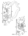
- an embodiment of an intervertabral prosthetic device is referred to, in general, by the reference numeral 60 and, is also adapted to be implanted between the spinous processes 22 of the vertebrae V4 and V5.
- the device includes the same spacers 42 and 44 of the previous embodiment but utilizes a different connecting mechanism, which is referred to, in general, by the reference numeral 62.
- the mechanism 62 includes a plate 64 extending from the end of the spacer 42 and connected to the spacer in any conventional manner, and a plate 66 extending from the end 44b of the spacer 44 and connected to the latter spacer in any conventional manner.
- the inner facing surfaces of the plates 64 and 66 are provided with teeth.
- a retainer 69 extends around the plates 64 and 66 and is partially shown in Fig. 6 in the interest of clarity.
- a spur gear 68 having teeth formed on its outer surface, is mounted between the plates 64 and 66 and between the ends of the bracket.
- the teeth of the gear 68 are in engagement with the teeth of the plates 64 and 68 so that rotation of the gear causes translational movement of the plates relative to each other.
- a conventional torsion spring can be attached to the gear 68 so that rotation of the gear in one direction cause the spring to coil up and tighten so that, when the rotation ceases the spring will uncoil and cause the gear to rotate in the other direction.
- An opening 68a is provided in the gear 68 that receives a tool, such as an Allen wrench, or the like, to permit the gear to be manually rotated.
- a tool such as an Allen wrench, or the like
- an opening would be provided in one of the end plates of the bracket 69 that would register with a corresponding end of the gear 68 to permit access to the opening 68a gear for this purpose.
- the device 60 would be inserted between the processes 22 of the vertebrae V4 and the vertebrae V5 in the same manner as the device 40, as discussed above.
- the surgeon can then rotate the gear 68 to adjust the spacing between the spacers 42 and 44 until the spinous processes 22 of the vertebrae V4 and V5 extend in the notches 42a and 44a, of the spacers 42 and 44, respectively, with an optimum fit.
- the distractor 59 shown in the embodiment of Fig. 5 , can be used to make the above adjustment
- the device can respond to various movements of the patient that place stress on the vertebral column 10 ( Fig. 1 ) and accommodate these movements by relative movement between the spacers 42 and 44. For example, if the patient bends backwardly, the spacers 42 and 44 would move closer together, with the gear 68 and the above spring permitting the relative axial movement. If the patient bends forwardly, then the axial spacing between the spacers 42 and 44 would increase, with the gear 68 and the spring permitting the relative axial movement. In both of the above cases, when the patient returns to a normal position the spring would rotate the gear 68 in the manner discussed above to move the spacers 42 and 44 back to their original position.
- the spacers 42 and 44 could reach a position in which their corresponding ends abut. In this position, the end of the spacer 42 that abuts the corresponding end of the spacer 44 would compress slightly since the spacer 42 is fabricated of a relative soft material.
- the device 40 is relatively easy to insert, provides an optimum fit between the processes of two adjacent vertebrae, and is adapted to vary in axial length in response to movements of the patient.
- the longitudinal, or axial, distance between the spacers 42 and 44 can be adjusted, depending on the distance between the processes 22 of the vertebrae V4 and V5.
- the device 60 is relatively easy to insert and provides an optimum fit between the two vertebrae V4 and V5.
- the above manual rotation of the gear 68 causes relative axial movement between the plates 64 and 66, and therefore the spacers 42 and 44.
- the longitudinal, or axial, distance between the spacers 42 and 44 can be adjusted, depending on the distance between the processes 22 of the vertebrae V4 and V5.
Abstract
Description
- The present invention relates to an intervertebral prosthetic device for stabilizing the human spine.
- Spinal discs that extend between adjacent vertebrae in vertebral columns of the human body provide critical support between the adjacent vertebrae. These discs can rupture, degenerate, and/or protrude by injury, degradation, disease, or the like to such a degree that the intervertebral space between adjacent vertebrae collapses as the disc loses at least a part of its support function, which can cause impingement of the nerve roots and severe pain.
- In these cases, intervertebral prosthetic devices have been designed that can be implanted between the adjacent vertebrae, both anterior and posterior of the column, to prevent the collapse of the intervertebral space between the adjacent vertebrae and thus stabilize the spine.
- However, many of these devices are relatively difficult to insert, and often do not provide an optimum fit with the anatomy.
-
US 2005/125061 A1 discloses an artificial replacement disk that is positionable between vertebrae comprising: an upper housing including an upper cavity; a lower housing including a lower cavity; and a first spacer and a second spacer. The first and second spacers are mounted on a shaft with a resisting member located between the first and the second spacers, which resisting member can urge the first and second spacers apart. The first and second spacers are partially located in the upper cavity and partially located in the lower cavity. -
DE 40 12 622 C1 -
WO 92/01428 A1 -
WO 98/22050 A1 -
US 5 653 763 A discloses an orthopaedic cage device having a rectangular cross-section and an intervertebral space shape conforming structure formed of two opposing shell elements being hinged at one end to form an interior volume therebetween. The surface of the interior volume is tapered in the axial direction. A threaded shaft is axially disposed in the interior volume and is held in place by a retaining ring slideably mounted at the non-hinged axial end of the device. A nut, being of substantially the same dimension as the maximum cross-section of the interior volume in its initial disposition, is disposed on the threaded shaft such that rotation of the shaft causes the nut to translate axially within the interior volume. This translation causes the nut to engage the tapered surface of the interior volume, which in turn causes the non-hinged end of the device to spread such that the device conforms to the natural space between the vertebral bones and provides for the proper curvature of the spine. -
WO 2004/026188 A2 discloses an intervertebral disc space implant including spaced-apart bone engagement portions that define an intermediate chamber that holds bone growth inducing material into contact with adjacent vertebral bodies. The implant is expandable to establish and maintain desired intervertebral spacing during fusion. The implant includes a first member and a second member arranged to move relative to each other by action of an expansion member, the first member being engageable with the vertebral body below the disc. - According to the present invention there is provided the prosthetic device of claim 1.
- There is hereinafter described and illustrated an embodiment of intravertebral prosthetic device which overcomes the above deficiencies by providing improved biomechanics and increased strength, in addition to being relatively easy to insert, yet provides an improved fit with the anatomy.
- An embodiment of prosthetic device will now be described, by way of example only, with reference to the accompanying drawings. It should be noted that the prosthetic device illustrated in
Fig. 5 is not in accordance with the present invention as now claimed, but it represents technical background that may be useful for understanding the prosthetic device of the present invention. -
-
Fig. 1 is a side elevational view of an adult human vertebral column. -
Fig. 2 is a posterior elevational view of the column ofFig. 1 . -
Fig. 3 is an enlarged, front elevational view of one of the vertebrae of the column ofFigs. 1. and 2 . -
Fig. 4 .is an enlarged, partial isometric view of a portion of the column ofFigs, 1 and 2 , depicting an interverbral prosthetic device inserted between two adjacent vertebrae. -
Fig. 5 is an enlarged, isometric, exploded view of the prosthetic device ofFig. 4 . - (
Fig.6 is a view similar to that ofFig. 5 , but depicting an embodiment of prosthetic device. - With reference to
Figs. 1 and 2 , thereference numeral 10 refiners, in general, to a humanvertebral column 10. The lower portion of thevertebral column 10 is shown and includes thelumbar region 12, the vertebrae V6, and thecoccyx 16. The flexible, soft portion of thevertebral column 10, which includes the thoracic region and the cervical region, is not shown. - The
lumbar region 12 of thevertebral column 10 includes five vertebrae V1. V2, V3, V4 and V5 separated by intervertebral discs D1, D2, D3, and D4, with the disc D1 extending between the vertebrae V1 and V2 the disc D2 extending between the vertebrae V2 and V3, the disc D3 extending between the vertebrae V3 and V4, and the disc D4 extending between the vertebrae V4 and V5. - The vertebrae V6 includes five fused vertebrae, one of which is a superior vertebrae V6 separated from the vertebrae V5 by a disc D5. The other four fused vertebrae of the
sacrum 14 are referred to collectively as V7. A disc D6 separates the vertebrae V6 from thecoccyx 16 which includes four fused vertebrae (not referenced). - With reference to
Fig. 3 , the vertebrae V4 includes twolaminate Fig. 2 ) of aspinous process 22 that extends posteriorly from the juncture of the two laminae. Twotransverse processes articular processes laminae articular processes laminae articular processes - Referring to
Fig. 4 , it will be assumed that, for one or more of the reasons set forth above, the vertebrae V4 and V5 are not being adequately supported by the disc D4 and that it is therefore necessary to provide supplemental support and stabilization of these vertebrae. To this end, an intervertebralprosthetic device 40 according to an embodiment of the invention is implanted between thespinous processes 22 of the vertebrae V4 and V5. - The
device 40 is shown in detail inFig. 5 and includes asolid spacer 42 having a substantially rectangular cross-section with the exception that a longitudinalcurved slot 42a is formed in one end portion. Theslot 42a is sized so as to receive aprocess 22 of any of the vertebrae V1-V7, including the vertebrae V4 shown inFig. 4 . Anothersolid spacer 44 is provided that has a substantially rectangular cross-section with the exception that a longitudinalcurved slot 44a is formed in one end portion. Theslot 44a receivers the process 22 (Fig. 4 ) from the vertebrae V5. Preferable, thespacers - An
adjustable mechanism 50 connects thespacers mechanism 50 consists of abracket 52 extending from the end 44b of thespacer 44, and connected to the spacer in any conventional manner. Thebracket 52 has a substantially U-shaped cross-section that includes abase 52a and two spaced, parallel,legs opening 52d extends through thebase 52a. - The
mechanism 50 also includes aplate 56 extending from the end of thespacer 42 and connected to the spacer in any conventional manner. Theplate 56 has a rectangular cross section and is sized so as to extend in thebracket 52, that is, in the area of thebracket 52 defined by thebase 52a and the twolegs elongate slot 56a is formed through theplate 56. - A
set screw 58 is provided that has an externally threaded shank-portion that extends through theslot 56a in theplate 56 and threadedly engages the threadedopening 52d in thebracket 52. Thescrew 58 has a head portion the diameter of which is greater than the with of theslot 56a. - As an initial set-up prior to the surgical procedure, the
plate 56 is positioned in thebracket 52, and thescrew 58 is expended through theslot 56a and in threaded engagement with theopening 52d of thebracket 52. Then, thescrew 58 is tightened only sufficiency to retain theplate 56 in thebracket 52 while permitting relative axial movement, of thespacers slot 56a defines the limits of the axial movement. - Referring to
Fig. 4 , thedevice 40 is inserted between theprocesses 22 of the vertebrae V4 and the vertebrae V5. The surgeon can then manually adjust the mechanism 50 (Fig. 5 ) and therefore the spacing between thespacers notches spacers Fig. 5 , can be used to assist in making the above adjustment, with the screw 88 tightened to the extent that it retains thespacers 42' and 44 in an extended position while permitting relative axial movement as necessary. When the optimum fit is achieved, theset screw 58 is tightened against theplate 56 to lock the plate to thebracket 52 and thus lock- thespacers - It can be appreciated that after the
device 40 has been implanted in the manner discussed above, the device can respond to various movements of the patent that place stress on the vertebral column 10 (Fig. 1 ) and accommodate these movements by relative movement between thespacers spacers set screw 58 permitting the relative axial movement. If the patient bends forwardly, then the axial spacing between thespacers set screw 58 permitting the relative axial movement. In both of the above cases, when the patient returns to a normal position theset screw 58 would permit thespacers - If the above backward movement is extreme, the
spacers spacer 42 that abuts the corresponding end of thespacer 44 would compress slightly since thespacer 42 is fabricated of a relative soft material. - Thus, the
device 40 is relatively easy to insert, provides an optimum fit between the processes of two adjacent vertebrae, and is adapted to vary in axial length in response to movement of the patient. - Referring to
Fig. 6 , an embodiment of an intervertabral prosthetic device is referred to, in general, by thereference numeral 60 and, is also adapted to be implanted between thespinous processes 22 of the vertebrae V4 and V5. - The device includes the
same spacers reference numeral 62. - The
mechanism 62 includes aplate 64 extending from the end of thespacer 42 and connected to the spacer in any conventional manner, and aplate 66 extending from the end 44b of thespacer 44 and connected to the latter spacer in any conventional manner. The inner facing surfaces of theplates retainer 69 extends around theplates Fig. 6 in the interest of clarity. - A
spur gear 68, having teeth formed on its outer surface, is mounted between theplates gear 68 are in engagement with the teeth of theplates gear 68 so that rotation of the gear in one direction cause the spring to coil up and tighten so that, when the rotation ceases the spring will uncoil and cause the gear to rotate in the other direction. - An
opening 68a is provided in thegear 68 that receives a tool, such as an Allen wrench, or the like, to permit the gear to be manually rotated. To this end, and although not shown in the drawings, it is understood that an opening would be provided in one of the end plates of thebracket 69 that would register with a corresponding end of thegear 68 to permit access to theopening 68a gear for this purpose. - Referring to
Fig. 4 , thedevice 60 would be inserted between theprocesses 22 of the vertebrae V4 and the vertebrae V5 in the same manner as thedevice 40, as discussed above. The surgeon can then rotate thegear 68 to adjust the spacing between thespacers notches spacers distractor 59, shown in the embodiment ofFig. 5 , can be used to make the above adjustment - It can be appreciated that after the
device 60 has been implanted in the manner discussed above, the device can respond to various movements of the patient that place stress on the vertebral column 10 (Fig. 1 ) and accommodate these movements by relative movement between thespacers spacers gear 68 and the above spring permitting the relative axial movement. If the patient bends forwardly, then the axial spacing between thespacers gear 68 and the spring permitting the relative axial movement. In both of the above cases, when the patient returns to a normal position the spring would rotate thegear 68 in the manner discussed above to move thespacers - Il the above backward movement is extreme, the
spacers spacer 42 that abuts the corresponding end of thespacer 44 would compress slightly since thespacer 42 is fabricated of a relative soft material. - Thus, the
device 40 is relatively easy to insert, provides an optimum fit between the processes of two adjacent vertebrae, and is adapted to vary in axial length in response to movements of the patient. - As a result, the longitudinal, or axial, distance between the
spacers processes 22 of the vertebrae V4 and V5. Thus, thedevice 60 is relatively easy to insert and provides an optimum fit between the two vertebrae V4 and V5. Thus, the above manual rotation of thegear 68 causes relative axial movement between theplates spacers spacers processes 22 of the vertebrae V4 and V5. - It is understood that variations may be made in the foregoing without departing from the invention and examples of some variations are as follows:
- Any conventional substance that promotes bone growth, such as HA coating, BMP, or the like, can be incorporated in the prosthetic device of one or both of the above embodiments;
- The surfaces of the
spacers notches 42a and 44b can be treated, such as by providing teeth, ridges, knurling, etc., to better grip the spinous processes and the adapters. - The spacer can be fabricated of a permanently deformable material thus providing a clamping action against the spinous process.
- One or both of the
spacers - The
spacers mechanisms - In the device of
Fig. 5 thebracket 52 can be connected to thespacer 42 and theplate 56 can be connected to thespacer 44. - One or both of the
spacers - In the device of
Fig 5 thebracket 52 can be locked to theplate 56 in manners other than by theset screw 58; - The prosthesis of the above embodiments can be placed between two vertebrae in the vertebral column other than the ones described above;
- Bilateral extrusions, or the like, can be provided on one or more of the devices to enable a tethering device to be attached;
- The prostheses can be inserted between two vertebrae following a discectemy in which a disc between the adjacent vertebrae is removed, or a corpectomy in which at least one vertebrae is removed.
- The prostheses can be inserted between the facets of adjacent vertebrae, rather than the spinous processes; and
- The spatial references made above, such as "under", "over", "between", "flexible, soft", "lower", "top", "bottom", etc. are for the purpose of illustration only and do not limit the specific orientation or location of the structure described above.
- The preceding specific embodiments are illustrative of the practice of the invention. It is to be understood, therefore, that other expedients known to those skilled in the art or disclosed herein, may be employed without departing from the invention, the scope of which is defined by the appended claims.
Claims (2)
- A prosthetic device for insertion between two vertebrae of a vertebral column to stabilize the same, the device comprising:a first spacer (42) for engaging one of the vertebrae;a second spacer (44) for engaging the other vertebrae; anda mechanism (62) for connecting the spacers and permitting relative movement between the spacers so that the distance between the spacers can vary to conform with the distance between the vertebrae;characterized in that the connecting mechanism (62) comprises:two plates (64, 66) respectively mounted to the spacers with each plate having teeth formed on one surface thereof;a gear (68) in engagement with the teeth so that rotation of the gear causes relative movement between the plates and therefore between the spacers, the gear extending between the two plates and having teeth mounted on its outer surface in engagement with the teeth on the plates; anda retainer (69) extending around the plates to retain the plates, and therefore the spacers, in different relative axial positions, the retainer having an opening (68a) formed therein to permit access to the gear so that it can be manually rotated.
- The device of claim 1, wherein the connecting mechanism (62) also permits relative movement between the spacers so as to accommodate bending movements of the vertebral column.
Applications Claiming Priority (2)
| Application Number | Priority Date | Filing Date | Title |
|---|---|---|---|
| US11/261,386 US8357181B2 (en) | 2005-10-27 | 2005-10-27 | Intervertebral prosthetic device for spinal stabilization and method of implanting same |
| PCT/US2006/060316 WO2007051172A1 (en) | 2005-10-27 | 2006-10-27 | Intervertebral prosthetic device for spinal stabilization and method of implanting same |
Publications (2)
| Publication Number | Publication Date |
|---|---|
| EP1951160A1 EP1951160A1 (en) | 2008-08-06 |
| EP1951160B1 true EP1951160B1 (en) | 2012-07-11 |
Family
ID=37775269
Family Applications (1)
| Application Number | Title | Priority Date | Filing Date |
|---|---|---|---|
| EP06839589A Not-in-force EP1951160B1 (en) | 2005-10-27 | 2006-10-27 | Intervertebral prosthetic device for spinal stabilization |
Country Status (7)
| Country | Link |
|---|---|
| US (1) | US8357181B2 (en) |
| EP (1) | EP1951160B1 (en) |
| JP (1) | JP2009513287A (en) |
| KR (1) | KR20080056022A (en) |
| AU (1) | AU2006305757A1 (en) |
| CA (1) | CA2624986A1 (en) |
| WO (1) | WO2007051172A1 (en) |
Families Citing this family (163)
| Publication number | Priority date | Publication date | Assignee | Title |
|---|---|---|---|---|
| US20050245937A1 (en) * | 2004-04-28 | 2005-11-03 | St. Francis Medical Technologies, Inc. | System and method for insertion of an interspinous process implant that is rotatable in order to retain the implant relative to the spinous processes |
| US20080039859A1 (en) | 1997-01-02 | 2008-02-14 | Zucherman James F | Spine distraction implant and method |
| US6068630A (en) | 1997-01-02 | 2000-05-30 | St. Francis Medical Technologies, Inc. | Spine distraction implant |
| US20080086212A1 (en) | 1997-01-02 | 2008-04-10 | St. Francis Medical Technologies, Inc. | Spine distraction implant |
| US7201751B2 (en) * | 1997-01-02 | 2007-04-10 | St. Francis Medical Technologies, Inc. | Supplemental spine fixation device |
| US7959652B2 (en) * | 2005-04-18 | 2011-06-14 | Kyphon Sarl | Interspinous process implant having deployable wings and method of implantation |
| US7549999B2 (en) | 2003-05-22 | 2009-06-23 | Kyphon Sarl | Interspinous process distraction implant and method of implantation |
| US8147548B2 (en) | 2005-03-21 | 2012-04-03 | Kyphon Sarl | Interspinous process implant having a thread-shaped wing and method of implantation |
| US8070778B2 (en) | 2003-05-22 | 2011-12-06 | Kyphon Sarl | Interspinous process implant with slide-in distraction piece and method of implantation |
| US8048117B2 (en) | 2003-05-22 | 2011-11-01 | Kyphon Sarl | Interspinous process implant and method of implantation |
| US7909853B2 (en) | 2004-09-23 | 2011-03-22 | Kyphon Sarl | Interspinous process implant including a binder and method of implantation |
| US8221463B2 (en) * | 2002-10-29 | 2012-07-17 | Kyphon Sarl | Interspinous process implants and methods of use |
| US7931674B2 (en) | 2005-03-21 | 2011-04-26 | Kyphon Sarl | Interspinous process implant having deployable wing and method of implantation |
| US7335203B2 (en) * | 2003-02-12 | 2008-02-26 | Kyphon Inc. | System and method for immobilizing adjacent spinous processes |
| US9161783B2 (en) | 2004-10-20 | 2015-10-20 | Vertiflex, Inc. | Interspinous spacer |
| US8409282B2 (en) | 2004-10-20 | 2013-04-02 | Vertiflex, Inc. | Systems and methods for posterior dynamic stabilization of the spine |
| US8123782B2 (en) | 2004-10-20 | 2012-02-28 | Vertiflex, Inc. | Interspinous spacer |
| US8425559B2 (en) | 2004-10-20 | 2013-04-23 | Vertiflex, Inc. | Systems and methods for posterior dynamic stabilization of the spine |
| US8012207B2 (en) | 2004-10-20 | 2011-09-06 | Vertiflex, Inc. | Systems and methods for posterior dynamic stabilization of the spine |
| US8167944B2 (en) | 2004-10-20 | 2012-05-01 | The Board Of Trustees Of The Leland Stanford Junior University | Systems and methods for posterior dynamic stabilization of the spine |
| US8945183B2 (en) | 2004-10-20 | 2015-02-03 | Vertiflex, Inc. | Interspinous process spacer instrument system with deployment indicator |
| US9023084B2 (en) | 2004-10-20 | 2015-05-05 | The Board Of Trustees Of The Leland Stanford Junior University | Systems and methods for stabilizing the motion or adjusting the position of the spine |
| US8128662B2 (en) | 2004-10-20 | 2012-03-06 | Vertiflex, Inc. | Minimally invasive tooling for delivery of interspinous spacer |
| US8152837B2 (en) | 2004-10-20 | 2012-04-10 | The Board Of Trustees Of The Leland Stanford Junior University | Systems and methods for posterior dynamic stabilization of the spine |
| US8317864B2 (en) | 2004-10-20 | 2012-11-27 | The Board Of Trustees Of The Leland Stanford Junior University | Systems and methods for posterior dynamic stabilization of the spine |
| US8123807B2 (en) | 2004-10-20 | 2012-02-28 | Vertiflex, Inc. | Systems and methods for posterior dynamic stabilization of the spine |
| US8273108B2 (en) | 2004-10-20 | 2012-09-25 | Vertiflex, Inc. | Interspinous spacer |
| US9119680B2 (en) | 2004-10-20 | 2015-09-01 | Vertiflex, Inc. | Interspinous spacer |
| US8277488B2 (en) | 2004-10-20 | 2012-10-02 | Vertiflex, Inc. | Interspinous spacer |
| US8613747B2 (en) | 2004-10-20 | 2013-12-24 | Vertiflex, Inc. | Spacer insertion instrument |
| US7763074B2 (en) | 2004-10-20 | 2010-07-27 | The Board Of Trustees Of The Leland Stanford Junior University | Systems and methods for posterior dynamic stabilization of the spine |
| US8241330B2 (en) | 2007-01-11 | 2012-08-14 | Lanx, Inc. | Spinous process implants and associated methods |
| US9055981B2 (en) | 2004-10-25 | 2015-06-16 | Lanx, Inc. | Spinal implants and methods |
| WO2006058221A2 (en) | 2004-11-24 | 2006-06-01 | Abdou Samy M | Devices and methods for inter-vertebral orthopedic device placement |
| CA2701050A1 (en) | 2004-12-06 | 2009-07-09 | Vertiflex, Inc. | Spacer insertion instrument |
| US8038698B2 (en) | 2005-02-17 | 2011-10-18 | Kphon Sarl | Percutaneous spinal implants and methods |
| US8096994B2 (en) | 2005-02-17 | 2012-01-17 | Kyphon Sarl | Percutaneous spinal implants and methods |
| US8029549B2 (en) * | 2005-02-17 | 2011-10-04 | Kyphon Sarl | Percutaneous spinal implants and methods |
| US8057513B2 (en) | 2005-02-17 | 2011-11-15 | Kyphon Sarl | Percutaneous spinal implants and methods |
| US7988709B2 (en) * | 2005-02-17 | 2011-08-02 | Kyphon Sarl | Percutaneous spinal implants and methods |
| US7993342B2 (en) * | 2005-02-17 | 2011-08-09 | Kyphon Sarl | Percutaneous spinal implants and methods |
| US7927354B2 (en) * | 2005-02-17 | 2011-04-19 | Kyphon Sarl | Percutaneous spinal implants and methods |
| US7998174B2 (en) * | 2005-02-17 | 2011-08-16 | Kyphon Sarl | Percutaneous spinal implants and methods |
| US8029567B2 (en) | 2005-02-17 | 2011-10-04 | Kyphon Sarl | Percutaneous spinal implants and methods |
| US8100943B2 (en) * | 2005-02-17 | 2012-01-24 | Kyphon Sarl | Percutaneous spinal implants and methods |
| US8007521B2 (en) | 2005-02-17 | 2011-08-30 | Kyphon Sarl | Percutaneous spinal implants and methods |
| US8034080B2 (en) | 2005-02-17 | 2011-10-11 | Kyphon Sarl | Percutaneous spinal implants and methods |
| US8097018B2 (en) | 2005-02-17 | 2012-01-17 | Kyphon Sarl | Percutaneous spinal implants and methods |
| US20070276493A1 (en) | 2005-02-17 | 2007-11-29 | Malandain Hugues F | Percutaneous spinal implants and methods |
| US8096995B2 (en) * | 2005-02-17 | 2012-01-17 | Kyphon Sarl | Percutaneous spinal implants and methods |
| US8157841B2 (en) | 2005-02-17 | 2012-04-17 | Kyphon Sarl | Percutaneous spinal implants and methods |
| US8066742B2 (en) * | 2005-03-31 | 2011-11-29 | Warsaw Orthopedic, Inc. | Intervertebral prosthetic device for spinal stabilization and method of implanting same |
| US8034079B2 (en) | 2005-04-12 | 2011-10-11 | Warsaw Orthopedic, Inc. | Implants and methods for posterior dynamic stabilization of a spinal motion segment |
| US7727233B2 (en) | 2005-04-29 | 2010-06-01 | Warsaw Orthopedic, Inc. | Spinous process stabilization devices and methods |
| US8357181B2 (en) | 2005-10-27 | 2013-01-22 | Warsaw Orthopedic, Inc. | Intervertebral prosthetic device for spinal stabilization and method of implanting same |
| US7862591B2 (en) * | 2005-11-10 | 2011-01-04 | Warsaw Orthopedic, Inc. | Intervertebral prosthetic device for spinal stabilization and method of implanting same |
| US8083795B2 (en) | 2006-01-18 | 2011-12-27 | Warsaw Orthopedic, Inc. | Intervertebral prosthetic device for spinal stabilization and method of manufacturing same |
| US7837711B2 (en) * | 2006-01-27 | 2010-11-23 | Warsaw Orthopedic, Inc. | Artificial spinous process for the sacrum and methods of use |
| US8262698B2 (en) | 2006-03-16 | 2012-09-11 | Warsaw Orthopedic, Inc. | Expandable device for insertion between anatomical structures and a procedure utilizing same |
| US8361116B2 (en) | 2006-03-24 | 2013-01-29 | U.S. Spine, Inc. | Non-pedicle based interspinous spacer |
| US8118844B2 (en) * | 2006-04-24 | 2012-02-21 | Warsaw Orthopedic, Inc. | Expandable device for insertion between anatomical structures and a procedure utilizing same |
| US8105357B2 (en) | 2006-04-28 | 2012-01-31 | Warsaw Orthopedic, Inc. | Interspinous process brace |
| US20070270823A1 (en) * | 2006-04-28 | 2007-11-22 | Sdgi Holdings, Inc. | Multi-chamber expandable interspinous process brace |
| US8048118B2 (en) | 2006-04-28 | 2011-11-01 | Warsaw Orthopedic, Inc. | Adjustable interspinous process brace |
| US8252031B2 (en) * | 2006-04-28 | 2012-08-28 | Warsaw Orthopedic, Inc. | Molding device for an expandable interspinous process implant |
| US8048119B2 (en) | 2006-07-20 | 2011-11-01 | Warsaw Orthopedic, Inc. | Apparatus for insertion between anatomical structures and a procedure utilizing same |
| FR2907329B1 (en) * | 2006-10-20 | 2009-02-27 | Jean Taylor | INTEREPINEAL VERTEBRAL PROSTHESIS |
| US20080086115A1 (en) | 2006-09-07 | 2008-04-10 | Warsaw Orthopedic, Inc. | Intercostal spacer device and method for use in correcting a spinal deformity |
| US8845726B2 (en) | 2006-10-18 | 2014-09-30 | Vertiflex, Inc. | Dilator |
| US8097019B2 (en) | 2006-10-24 | 2012-01-17 | Kyphon Sarl | Systems and methods for in situ assembly of an interspinous process distraction implant |
| FR2908035B1 (en) | 2006-11-08 | 2009-05-01 | Jean Taylor | INTEREPINE IMPLANT |
| US7879104B2 (en) | 2006-11-15 | 2011-02-01 | Warsaw Orthopedic, Inc. | Spinal implant system |
| US7955392B2 (en) * | 2006-12-14 | 2011-06-07 | Warsaw Orthopedic, Inc. | Interspinous process devices and methods |
| US20080167655A1 (en) * | 2007-01-05 | 2008-07-10 | Jeffrey Chun Wang | Interspinous implant, tools and methods of implanting |
| US9265532B2 (en) | 2007-01-11 | 2016-02-23 | Lanx, Inc. | Interspinous implants and methods |
| US9107702B2 (en) * | 2007-02-06 | 2015-08-18 | Zimmer Gmbh | Central structures spreader for the lumbar spine |
| WO2008106140A2 (en) | 2007-02-26 | 2008-09-04 | Abdou M Samy | Spinal stabilization systems and methods of use |
| CA2684461C (en) | 2007-04-16 | 2015-06-30 | Vertiflex Inc. | Interspinous spacer |
| US8840646B2 (en) * | 2007-05-10 | 2014-09-23 | Warsaw Orthopedic, Inc. | Spinous process implants and methods |
| US20080294200A1 (en) * | 2007-05-25 | 2008-11-27 | Andrew Kohm | Spinous process implants and methods of using the same |
| CN101778603B (en) * | 2007-08-20 | 2012-02-08 | 新特斯有限责任公司 | Ratcheting epiphysiodesis plate |
| US8388663B2 (en) * | 2007-09-13 | 2013-03-05 | Stryker Spine | Dynamic cervical plate |
| EP2244670B1 (en) | 2008-01-15 | 2017-09-13 | Vertiflex, Inc. | Interspinous spacer |
| US20090198338A1 (en) * | 2008-02-04 | 2009-08-06 | Phan Christopher U | Medical implants and methods |
| EP2087857A1 (en) * | 2008-02-07 | 2009-08-12 | K2M, Inc. | Expandable vertebral device with cam lock |
| US8114136B2 (en) | 2008-03-18 | 2012-02-14 | Warsaw Orthopedic, Inc. | Implants and methods for inter-spinous process dynamic stabilization of a spinal motion segment |
| US8343190B1 (en) | 2008-03-26 | 2013-01-01 | Nuvasive, Inc. | Systems and methods for spinous process fixation |
| AU2009228030B2 (en) | 2008-03-28 | 2014-01-16 | K2M, Inc. | Expandable cage with locking device |
| EP2268219B1 (en) * | 2008-03-28 | 2016-11-09 | K2M, Inc. | Expandable cage |
| EP2430995B1 (en) * | 2008-08-08 | 2016-03-30 | Alphatec Spine, Inc. | Spinous process device |
| CN102164552A (en) * | 2008-08-13 | 2011-08-24 | 斯恩蒂斯有限公司 | Interspinous spacer assembly |
| WO2010048396A2 (en) * | 2008-10-23 | 2010-04-29 | Linares Maedical Devices, Llc | Support insert associated with spinal vertebrae |
| US8114131B2 (en) | 2008-11-05 | 2012-02-14 | Kyphon Sarl | Extension limiting devices and methods of use for the spine |
| IT1392200B1 (en) * | 2008-12-17 | 2012-02-22 | N B R New Biotechnology Res | MODULAR VERTEBRAL STABILIZER. |
| US8114135B2 (en) * | 2009-01-16 | 2012-02-14 | Kyphon Sarl | Adjustable surgical cables and methods for treating spinal stenosis |
| EP2413825A4 (en) | 2009-03-31 | 2013-12-11 | Lanx Inc | Spinous process implants and associated methods |
| US20100286701A1 (en) * | 2009-05-08 | 2010-11-11 | Kyphon Sarl | Distraction tool for distracting an interspinous space |
| US8372117B2 (en) | 2009-06-05 | 2013-02-12 | Kyphon Sarl | Multi-level interspinous implants and methods of use |
| US8157842B2 (en) | 2009-06-12 | 2012-04-17 | Kyphon Sarl | Interspinous implant and methods of use |
| IT1399785B1 (en) | 2009-07-17 | 2013-05-03 | Ceccarelli | INTERVERTEBRAL SPACER DEVICE |
| PL217862B1 (en) * | 2009-10-09 | 2014-08-29 | Lfc Spółka Z Ograniczoną Odpowiedzialnością | Off-load-dynamic intervertebral device |
| US8764806B2 (en) | 2009-12-07 | 2014-07-01 | Samy Abdou | Devices and methods for minimally invasive spinal stabilization and instrumentation |
| EP2512357B1 (en) | 2009-12-15 | 2016-07-13 | Vertiflex, Inc. | Spinal spacer for cervical and other vertebra, and associated systems |
| US8114132B2 (en) | 2010-01-13 | 2012-02-14 | Kyphon Sarl | Dynamic interspinous process device |
| US20110172720A1 (en) * | 2010-01-13 | 2011-07-14 | Kyphon Sarl | Articulating interspinous process clamp |
| US8317831B2 (en) | 2010-01-13 | 2012-11-27 | Kyphon Sarl | Interspinous process spacer diagnostic balloon catheter and methods of use |
| US8246656B2 (en) * | 2010-02-25 | 2012-08-21 | Depuy Spine, Inc. | Crossover spinous process implant |
| US8147526B2 (en) | 2010-02-26 | 2012-04-03 | Kyphon Sarl | Interspinous process spacer diagnostic parallel balloon catheter and methods of use |
| CA2787847A1 (en) * | 2010-03-04 | 2011-09-09 | Synthes Usa, Llc | Expandable lamina spinal fusion implant |
| DE102010018379B4 (en) * | 2010-04-26 | 2018-10-18 | Peter Metz-Stavenhagen | Spine implant and tool for this |
| US8814908B2 (en) | 2010-07-26 | 2014-08-26 | Warsaw Orthopedic, Inc. | Injectable flexible interspinous process device system |
| US8480747B2 (en) * | 2010-08-11 | 2013-07-09 | Warsaw Orthopedic, Inc. | Interbody spinal implants with extravertebral support plates |
| CA2811562C (en) * | 2010-09-27 | 2017-11-21 | Apifix Ltd. | Ratcheted spinal device |
| US8636774B2 (en) | 2010-12-17 | 2014-01-28 | Spinal Usa, Inc. | Spinal implant apparatuses and methods of implanting and using same |
| US8740980B2 (en) | 2011-01-27 | 2014-06-03 | Warsaw Orthopedic, Inc. | Expandable medical implant |
| US8496689B2 (en) | 2011-02-23 | 2013-07-30 | Farzad Massoudi | Spinal implant device with fusion cage and fixation plates and method of implanting |
| US8562650B2 (en) | 2011-03-01 | 2013-10-22 | Warsaw Orthopedic, Inc. | Percutaneous spinous process fusion plate assembly and method |
| US8425560B2 (en) | 2011-03-09 | 2013-04-23 | Farzad Massoudi | Spinal implant device with fixation plates and lag screws and method of implanting |
| US8591548B2 (en) | 2011-03-31 | 2013-11-26 | Warsaw Orthopedic, Inc. | Spinous process fusion plate assembly |
| US8591549B2 (en) | 2011-04-08 | 2013-11-26 | Warsaw Orthopedic, Inc. | Variable durometer lumbar-sacral implant |
| DE102011018692B4 (en) | 2011-04-26 | 2016-06-23 | Peter Metz-Stavenhagen | Spinal implant, tool and method of distraction of the spinal implant |
| US20120323276A1 (en) | 2011-06-17 | 2012-12-20 | Bryan Okamoto | Expandable interspinous device |
| USD757943S1 (en) | 2011-07-14 | 2016-05-31 | Nuvasive, Inc. | Spinous process plate |
| US8882805B1 (en) | 2011-08-02 | 2014-11-11 | Lawrence Maccree | Spinal fixation system |
| US8845728B1 (en) | 2011-09-23 | 2014-09-30 | Samy Abdou | Spinal fixation devices and methods of use |
| US11812923B2 (en) | 2011-10-07 | 2023-11-14 | Alan Villavicencio | Spinal fixation device |
| US9675470B2 (en) * | 2011-10-19 | 2017-06-13 | P&H Medical Products, Llc | Laterally expandable spinal prosthesis |
| US10166048B2 (en) | 2011-11-02 | 2019-01-01 | Tenzin Llc | Translational instrumentation for spondylolisthesis and scoliosis reduction |
| WO2013123497A1 (en) * | 2012-02-17 | 2013-08-22 | The Unversity Of Toledo | Hybrid multifunctional posterior interspinous fusion device |
| US20130226240A1 (en) | 2012-02-22 | 2013-08-29 | Samy Abdou | Spinous process fixation devices and methods of use |
| US10448977B1 (en) * | 2012-03-31 | 2019-10-22 | Ali H. MESIWALA | Interspinous device and related methods |
| US8808328B2 (en) * | 2012-04-05 | 2014-08-19 | Tufts Medical Center, Inc. | Spring loaded mechanism for managing scoliosis |
| US8771277B2 (en) | 2012-05-08 | 2014-07-08 | Globus Medical, Inc | Device and a method for implanting a spinous process fixation device |
| US9198767B2 (en) | 2012-08-28 | 2015-12-01 | Samy Abdou | Devices and methods for spinal stabilization and instrumentation |
| US9320617B2 (en) | 2012-10-22 | 2016-04-26 | Cogent Spine, LLC | Devices and methods for spinal stabilization and instrumentation |
| US9198697B2 (en) | 2013-03-13 | 2015-12-01 | Globus Medical, Inc. | Spinous process fixation system and methods thereof |
| US9486251B2 (en) | 2012-12-31 | 2016-11-08 | Globus Medical, Inc. | Spinous process fixation system and methods thereof |
| US9011493B2 (en) | 2012-12-31 | 2015-04-21 | Globus Medical, Inc. | Spinous process fixation system and methods thereof |
| US9456908B2 (en) | 2013-03-12 | 2016-10-04 | Coorstek Medical Llc | Fusion cage |
| US9707096B2 (en) | 2013-03-14 | 2017-07-18 | K2M, Inc. | Spinal fixation device |
| US9028498B2 (en) | 2013-03-14 | 2015-05-12 | Innovasis, Inc. | Modular bone fixation plate assembly |
| US10292832B2 (en) | 2013-03-14 | 2019-05-21 | Ohio State Innovation Foundation | Spinal fixation device |
| US9675303B2 (en) | 2013-03-15 | 2017-06-13 | Vertiflex, Inc. | Visualization systems, instruments and methods of using the same in spinal decompression procedures |
| US9480502B2 (en) * | 2013-05-16 | 2016-11-01 | Smokey Mountain Spine, Llc | Expansion interspinous fixation device and method |
| EP2848222A3 (en) * | 2013-09-14 | 2015-03-25 | Paonan Biotech Co., Ltd | Vertebral fixation apparatus |
| US9962204B2 (en) * | 2014-04-12 | 2018-05-08 | Seyed Alireza Mirghasemi | Modular bone plate |
| US10524772B2 (en) | 2014-05-07 | 2020-01-07 | Vertiflex, Inc. | Spinal nerve decompression systems, dilation systems, and methods of using the same |
| US10130487B2 (en) | 2014-08-22 | 2018-11-20 | Globus Medical, Inc. | Vertebral implants and related methods of use |
| US9931138B2 (en) * | 2014-10-15 | 2018-04-03 | Globus Medical, Inc. | Orthopedic extendable rods |
| US9763707B2 (en) * | 2015-07-21 | 2017-09-19 | Asfora Ip, Llc | Interspinous process device and method |
| EP3349695B1 (en) | 2015-09-18 | 2020-11-18 | K2M, Inc. | Corpectomy device |
| US10857003B1 (en) | 2015-10-14 | 2020-12-08 | Samy Abdou | Devices and methods for vertebral stabilization |
| US10973648B1 (en) | 2016-10-25 | 2021-04-13 | Samy Abdou | Devices and methods for vertebral bone realignment |
| US10744000B1 (en) | 2016-10-25 | 2020-08-18 | Samy Abdou | Devices and methods for vertebral bone realignment |
| US11179248B2 (en) | 2018-10-02 | 2021-11-23 | Samy Abdou | Devices and methods for spinal implantation |
| CN109077835A (en) * | 2018-10-26 | 2018-12-25 | 北京爱康宜诚医疗器材有限公司 | Centrum prosthese |
| US11660205B2 (en) | 2019-08-15 | 2023-05-30 | Adcura, Inc. | Dual-axis adjustable spinal systems and interbody fusion devices with fixation |
| WO2021030644A1 (en) * | 2019-08-15 | 2021-02-18 | Spineex, Inc. | Translating dual axis adjustable interbody fusion spinal system |
| US11627997B1 (en) * | 2020-10-01 | 2023-04-18 | Jason Zook | Lumbar spinous process static and dynamic stabilization device |
| US20230130877A1 (en) * | 2021-10-22 | 2023-04-27 | Linares Spinal Devices, Llc | Expandable spinal jack for installation between upper and lower succeeding superior articular processes |
| US11432937B1 (en) * | 2021-11-02 | 2022-09-06 | Linares Medical Devices, Llc | Expandable spinal jack for installation between upper and lower succeeding superior articular processes |
| US11896268B2 (en) * | 2022-01-24 | 2024-02-13 | Linares Spinal Devices, Llc | Expandable spinal rack gear jack for installation between upper and lower succeeding superior articular processes |
| TWI819504B (en) * | 2022-02-25 | 2023-10-21 | 寶億生技股份有限公司 | Interspinous process device and device for stabilizing thereof |
Family Cites Families (396)
| Publication number | Priority date | Publication date | Assignee | Title |
|---|---|---|---|---|
| US2677369A (en) * | 1952-03-26 | 1954-05-04 | Fred L Knowles | Apparatus for treatment of the spinal column |
| US3648691A (en) * | 1970-02-24 | 1972-03-14 | Univ Colorado State Res Found | Method of applying vertebral appliance |
| GB1519139A (en) | 1974-06-18 | 1978-07-26 | Crock H V And Pericic L | L securing elongate members to structurs more especially in surgical procedures |
| US4011602A (en) * | 1975-10-06 | 1977-03-15 | Battelle Memorial Institute | Porous expandable device for attachment to bone tissue |
| PL114098B1 (en) * | 1978-04-14 | 1981-01-31 | Wyzsza Szkola Inzynierska | Apparatus for correcting spinal curvature |
| CH628803A5 (en) | 1978-05-12 | 1982-03-31 | Sulzer Ag | Implant insertable between adjacent vertebrae |
| SU988281A1 (en) | 1981-06-26 | 1983-01-15 | За витель | Vertical column fixing device |
| US4554914A (en) | 1983-10-04 | 1985-11-26 | Kapp John P | Prosthetic vertebral body |
| FR2553993B1 (en) | 1983-10-28 | 1986-02-07 | Peze William | METHOD AND APPARATUS FOR DYNAMIC CORRECTION OF SPINAL DEFORMATIONS |
| GB8333442D0 (en) | 1983-12-15 | 1984-01-25 | Showell A W Sugicraft Ltd | Devices for spinal fixation |
| US4611582A (en) | 1983-12-27 | 1986-09-16 | Wisconsin Alumni Research Foundation | Vertebral clamp |
| US4604995A (en) | 1984-03-30 | 1986-08-12 | Stephens David C | Spinal stabilizer |
| US4573454A (en) * | 1984-05-17 | 1986-03-04 | Hoffman Gregory A | Spinal fixation apparatus |
| FR2575059B1 (en) * | 1984-12-21 | 1988-11-10 | Daher Youssef | SHORING DEVICE FOR USE IN A VERTEBRAL PROSTHESIS |
| US4743260A (en) | 1985-06-10 | 1988-05-10 | Burton Charles V | Method for a flexible stabilization system for a vertebral column |
| SE458417B (en) * | 1985-08-15 | 1989-04-03 | Sven Olerud | FIXING INSTRUMENTS PROVIDED FOR USE IN SPINE OPERATIONS |
| US4771767A (en) | 1986-02-03 | 1988-09-20 | Acromed Corporation | Apparatus and method for maintaining vertebrae in a desired relationship |
| DE3614101C1 (en) | 1986-04-25 | 1987-10-22 | Juergen Prof Dr Med Harms | Pedicle screw |
| US4931055A (en) * | 1986-05-30 | 1990-06-05 | John Bumpus | Distraction rods |
| GB8620937D0 (en) | 1986-08-29 | 1986-10-08 | Shepperd J A N | Spinal implant |
| GB8622563D0 (en) | 1986-09-19 | 1986-10-22 | Amis A A | Artificial ligaments |
| SU1484348A1 (en) | 1987-03-04 | 1989-06-07 | Белорусский научно-исследовательский институт травматологии и ортопедии | Spinal column fixing device |
| FR2623085B1 (en) * | 1987-11-16 | 1992-08-14 | Breard Francis | SURGICAL IMPLANT TO LIMIT THE RELATIVE MOVEMENT OF VERTEBRES |
| FR2625097B1 (en) | 1987-12-23 | 1990-05-18 | Cote Sarl | INTER-SPINOUS PROSTHESIS COMPOSED OF SEMI-ELASTIC MATERIAL COMPRISING A TRANSFILING EYE AT ITS END AND INTER-SPINOUS PADS |
| US4887596A (en) | 1988-03-02 | 1989-12-19 | Synthes (U.S.A.) | Open backed pedicle screw |
| US5609635A (en) * | 1988-06-28 | 1997-03-11 | Michelson; Gary K. | Lordotic interbody spinal fusion implants |
| GB8825909D0 (en) | 1988-11-04 | 1988-12-07 | Showell A W Sugicraft Ltd | Pedicle engaging means |
| US5201734A (en) * | 1988-12-21 | 1993-04-13 | Zimmer, Inc. | Spinal locking sleeve assembly |
| FR2642645B1 (en) * | 1989-02-03 | 1992-08-14 | Breard Francis | FLEXIBLE INTERVERTEBRAL STABILIZER AND METHOD AND APPARATUS FOR CONTROLLING ITS VOLTAGE BEFORE PLACEMENT ON THE RACHIS |
| USRE36221E (en) | 1989-02-03 | 1999-06-01 | Breard; Francis Henri | Flexible inter-vertebral stabilizer as well as process and apparatus for determining or verifying its tension before installation on the spinal column |
| JPH0620466B2 (en) * | 1989-03-31 | 1994-03-23 | 有限会社田中医科器械製作所 | Spinal column correction device |
| US5098433A (en) * | 1989-04-12 | 1992-03-24 | Yosef Freedland | Winged compression bolt orthopedic fastener |
| DE3922044A1 (en) | 1989-07-05 | 1991-02-07 | Richter Turtur Matthias Dr | Treatment of fractured vertebra - by instrument which avoids any force on intact adjacent to vertebrae |
| DE8912648U1 (en) * | 1989-10-23 | 1990-11-22 | Mecron Medizinische Produkte Gmbh, 1000 Berlin, De | |
| US5002542A (en) | 1989-10-30 | 1991-03-26 | Synthes U.S.A. | Pedicle screw clamp |
| US5059193A (en) | 1989-11-20 | 1991-10-22 | Spine-Tech, Inc. | Expandable spinal implant and surgical method |
| US5345927A (en) * | 1990-03-02 | 1994-09-13 | Bonutti Peter M | Arthroscopic retractors |
| DE4012622C1 (en) | 1990-04-20 | 1991-07-18 | Eska Medical Luebeck Medizintechnik Gmbh & Co, 2400 Luebeck, De | Two-part metal vertebra implant - has parts locked by two toothed racks, pre-stressed by elastic cushion between both implant parts |
| DE9006646U1 (en) | 1990-06-13 | 1990-08-23 | Howmedica Gmbh, 2314 Schoenkirchen, De | |
| AT394307B (en) | 1990-07-24 | 1992-03-10 | Mohamed Ibrahim Dr Rasheed | SPINE PROSTHESIS |
| FR2666981B1 (en) | 1990-09-21 | 1993-06-25 | Commarmond Jacques | SYNTHETIC LIGAMENT VERTEBRAL. |
| US6347240B1 (en) | 1990-10-19 | 2002-02-12 | St. Louis University | System and method for use in displaying images of a body part |
| DE69132412T2 (en) | 1990-10-19 | 2001-03-01 | Univ St Louis | LOCALIZATION SYSTEM FOR A SURGICAL PROBE FOR USE ON THE HEAD |
| US5047055A (en) | 1990-12-21 | 1991-09-10 | Pfizer Hospital Products Group, Inc. | Hydrogel intervertebral disc nucleus |
| FR2672202B1 (en) | 1991-02-05 | 1993-07-30 | Safir | BONE SURGICAL IMPLANT, ESPECIALLY FOR INTERVERTEBRAL STABILIZER. |
| US5171278A (en) | 1991-02-22 | 1992-12-15 | Madhavan Pisharodi | Middle expandable intervertebral disk implants |
| US5390683A (en) * | 1991-02-22 | 1995-02-21 | Pisharodi; Madhavan | Spinal implantation methods utilizing a middle expandable implant |
| FR2676911B1 (en) | 1991-05-30 | 1998-03-06 | Psi Ste Civile Particuliere | INTERVERTEBRAL STABILIZATION DEVICE WITH SHOCK ABSORBERS. |
| FR2681525A1 (en) | 1991-09-19 | 1993-03-26 | Medical Op | Device for flexible or semi-rigid stabilisation of the spine, in particular of the human spine, by a posterior route |
| DE9112466U1 (en) | 1991-10-07 | 1991-12-05 | Howmedica Gmbh, 2314 Schoenkirchen, De | |
| CH686610A5 (en) * | 1991-10-18 | 1996-05-15 | Pina Vertriebs Ag | Compression implant. |
| DE4200905A1 (en) | 1992-01-16 | 1993-07-22 | Heinrich Ulrich | IMPLANT FOR ALIGNMENT AND FIXING OF TWO BONES OR BONE PARTS TOGETHER, IN PARTICULAR SPONDYLODESE IMPLANT |
| US5217461A (en) | 1992-02-20 | 1993-06-08 | Acromed Corporation | Apparatus for maintaining vertebrae in a desired spatial relationship |
| DE9202745U1 (en) | 1992-03-02 | 1992-04-30 | Howmedica Gmbh, 2314 Schoenkirchen, De | |
| FR2689750B1 (en) | 1992-04-10 | 1997-01-31 | Eurosurgical | BONE ANCHORING ELEMENT AND SPINAL OSTEOSYNTHESIS DEVICE INCORPORATING SUCH ELEMENTS. |
| FR2692952B1 (en) | 1992-06-25 | 1996-04-05 | Psi | IMPROVED SHOCK ABSORBER WITH MOVEMENT LIMIT. |
| FR2693364B1 (en) * | 1992-07-07 | 1995-06-30 | Erpios Snc | INTERVERTEBRAL PROSTHESIS FOR STABILIZING ROTATORY AND FLEXIBLE-EXTENSION CONSTRAINTS. |
| DE9213656U1 (en) * | 1992-10-09 | 1992-12-03 | Angiomed Ag, 7500 Karlsruhe, De | |
| EP1149560A3 (en) | 1992-11-12 | 2002-03-06 | ALLEYNE, Neville | Spinal protection device |
| US5306275A (en) * | 1992-12-31 | 1994-04-26 | Bryan Donald W | Lumbar spine fixation apparatus and method |
| US5527314A (en) | 1993-01-04 | 1996-06-18 | Danek Medical, Inc. | Spinal fixation system |
| US5540703A (en) * | 1993-01-06 | 1996-07-30 | Smith & Nephew Richards Inc. | Knotted cable attachment apparatus formed of braided polymeric fibers |
| US5456722A (en) | 1993-01-06 | 1995-10-10 | Smith & Nephew Richards Inc. | Load bearing polymeric cable |
| US5496318A (en) * | 1993-01-08 | 1996-03-05 | Advanced Spine Fixation Systems, Inc. | Interspinous segmental spine fixation device |
| FR2700941A1 (en) | 1993-02-03 | 1994-08-05 | Felman Daniel | Monobloc interspinal intervertebral fixation implant |
| DE4303770C1 (en) | 1993-02-09 | 1994-05-26 | Plus Endoprothetik Ag Rotkreuz | Stiffening and correction system for spinal vertebrae - comprises screw-ended holders with connecting rod supporting clamped distance pieces. |
| US5413576A (en) | 1993-02-10 | 1995-05-09 | Rivard; Charles-Hilaire | Apparatus for treating spinal disorder |
| FR2701650B1 (en) | 1993-02-17 | 1995-05-24 | Psi | Double shock absorber for intervertebral stabilization. |
| US5415661A (en) * | 1993-03-24 | 1995-05-16 | University Of Miami | Implantable spinal assist device |
| FR2703239B1 (en) | 1993-03-30 | 1995-06-02 | Brio Bio Rhone Implant Medical | Clip for interspinous prosthesis. |
| CA2161430C (en) | 1993-04-26 | 2001-07-03 | Richard D. Bucholz | System and method for indicating the position of a surgical probe |
| FR2707864B1 (en) | 1993-07-23 | 1996-07-19 | Jean Taylor | Surgical forceps for tensioning an osteosynthesis ligament. |
| US5360430A (en) | 1993-07-29 | 1994-11-01 | Lin Chih I | Intervertebral locking device |
| FR2709247B1 (en) | 1993-08-27 | 1995-09-29 | Martin Jean Raymond | Device for anchoring spinal instrumentation on a vertebra. |
| FR2709246B1 (en) | 1993-08-27 | 1995-09-29 | Martin Jean Raymond | Dynamic implanted spinal orthosis. |
| US5454812A (en) | 1993-11-12 | 1995-10-03 | Lin; Chih-I | Spinal clamping device having multiple distance adjusting strands |
| FR2712481B1 (en) | 1993-11-18 | 1996-01-12 | Graf Henry | Improvements to flexible inter-vertebral stabilizers. |
| FR2715057B1 (en) | 1994-01-18 | 1996-03-01 | Francis Henri Breard | Overall device for stabilizing the spine. |
| FR2715293B1 (en) | 1994-01-26 | 1996-03-22 | Biomat | Vertebral interbody fusion cage. |
| NL9400210A (en) | 1994-02-10 | 1995-09-01 | Acromed Bv | Implantation device for limiting movements between two vertebrae. |
| EP0669109B1 (en) | 1994-02-28 | 1999-05-26 | Sulzer Orthopädie AG | Stabilizer for adjacent vertebrae |
| EP0677277A3 (en) | 1994-03-18 | 1996-02-28 | Patrice Moreau | Spinal prosthetic assembly. |
| FR2717675B1 (en) | 1994-03-24 | 1996-05-03 | Jean Taylor | Interspinous wedge. |
| FR2719763B1 (en) | 1994-05-11 | 1996-09-27 | Jean Taylor | Vertebral implant. |
| FR2721501B1 (en) | 1994-06-24 | 1996-08-23 | Fairant Paulette | Prostheses of the vertebral articular facets. |
| FR2722088B1 (en) | 1994-07-08 | 1998-01-23 | Cahlik Marc Andre | SURGICAL IMPLANT FOR STABILIZING THE INTERVERTEBRAL SPACE |
| FR2722087A1 (en) | 1994-07-08 | 1996-01-12 | Cahlik Marc Andre | Surgical implant for limiting relative movement of vertebrae |
| FR2722980B1 (en) * | 1994-07-26 | 1996-09-27 | Samani Jacques | INTERTEPINOUS VERTEBRAL IMPLANT |
| DE9413471U1 (en) | 1994-08-20 | 1995-12-21 | Schaefer Micomed Gmbh | Ventral intervertebral implant |
| EP0700671B1 (en) | 1994-09-08 | 2001-08-08 | Stryker Technologies Corporation | Hydrogel intervertebral disc nucleus |
| FR2724554B1 (en) | 1994-09-16 | 1997-01-24 | Voydeville Gilles | DEVICE FOR FIXING A LIGAMENT PROSTHESIS |
| CA2201877C (en) | 1994-10-07 | 2004-06-08 | Richard D. Bucholz | Surgical navigation systems including reference and localization frames |
| US6978166B2 (en) | 1994-10-07 | 2005-12-20 | Saint Louis University | System for use in displaying images of a body part |
| JPH10507386A (en) | 1994-10-17 | 1998-07-21 | レイメディカ, インコーポレイテッド | Artificial spinal disc nucleus |
| FR2725892A1 (en) | 1994-10-21 | 1996-04-26 | Felman Daniel | Vertebral implant insertion process using shape memory material |
| US6004322A (en) | 1994-10-25 | 1999-12-21 | Sdgi Holdings, Inc. | Modular pedicle screw system |
| US5674296A (en) | 1994-11-14 | 1997-10-07 | Spinal Dynamics Corporation | Human spinal disc prosthesis |
| US5593408A (en) | 1994-11-30 | 1997-01-14 | Sofamor S.N.C | Vertebral instrumentation rod |
| FR2728159B1 (en) | 1994-12-16 | 1997-06-27 | Tornier Sa | ELASTIC DISC PROSTHESIS |
| US5665122A (en) | 1995-01-31 | 1997-09-09 | Kambin; Parviz | Expandable intervertebral cage and surgical method |
| FR2730156B1 (en) | 1995-02-03 | 1997-04-30 | Textile Hi Tec | INTER SPINOUS HOLD |
| US6592588B1 (en) | 1995-02-16 | 2003-07-15 | Arthrex, Inc. | Apparatus for osteochondral autograft transplantation |
| US5919196A (en) | 1995-02-16 | 1999-07-06 | Arthrex, Inc. | Method and apparatus for osteochondral autograft transplantation |
| ES2161865T3 (en) * | 1995-03-08 | 2001-12-16 | Synthes Ag | INTERVERTEBRAL IMPLANT |
| FR2731643A1 (en) | 1995-03-16 | 1996-09-20 | Jbs Sa | Angular screwdriver for access of awkwardly placed screws for use in surgery |
| FR2735351B1 (en) | 1995-06-13 | 1997-09-12 | Sofamor | IMPLANT FOR THE SURGICAL TREATMENT OF A VERTEBRAL ISTHMIC FRACTURE |
| DE19529605C2 (en) * | 1995-08-11 | 1997-10-09 | Bernhard Zientek | Intervertebral implant |
| CA2229714C (en) | 1995-10-20 | 2003-12-30 | Synthes (U.S.A.) | Intervertebral implant with compressible shaped hollow element |
| DE19541114A1 (en) * | 1995-10-26 | 1997-04-30 | Artos Med Produkte | Intervertebral implant |
| US5690649A (en) | 1995-12-05 | 1997-11-25 | Li Medical Technologies, Inc. | Anchor and anchor installation tool and method |
| US5653763A (en) | 1996-03-29 | 1997-08-05 | Fastenetix, L.L.C. | Intervertebral space shape conforming cage device |
| US6167145A (en) | 1996-03-29 | 2000-12-26 | Surgical Navigation Technologies, Inc. | Bone navigation system |
| US5702455A (en) | 1996-07-03 | 1997-12-30 | Saggar; Rahul | Expandable prosthesis for spinal fusion |
| US6009212A (en) | 1996-07-10 | 1999-12-28 | Washington University | Method and apparatus for image registration |
| FR2751202B1 (en) | 1996-07-22 | 2001-03-16 | Zacouto Fred | SKELETAL IMPLANT |
| FR2751864B1 (en) | 1996-08-01 | 1999-04-30 | Graf Henry | DEVICE FOR MECHANICALLY CONNECTING AND ASSISTING VERTEBRES BETWEEN THEM |
| EP0927011B1 (en) * | 1996-09-04 | 2003-01-22 | SYNTHES AG Chur | Intervertebral implant |
| US5716416A (en) * | 1996-09-10 | 1998-02-10 | Lin; Chih-I | Artificial intervertebral disk and method for implanting the same |
| US5921987A (en) | 1996-09-13 | 1999-07-13 | Depuy Orthopaedic Technology, Inc. | Articular cartilage transplant instrument set |
| US5964805A (en) | 1997-02-12 | 1999-10-12 | Stone; Kevin R. | Method and paste for articular cartilage transplantation |
| US5810815A (en) | 1996-09-20 | 1998-09-22 | Morales; Jose A. | Surgical apparatus for use in the treatment of spinal deformities |
| US6190414B1 (en) * | 1996-10-31 | 2001-02-20 | Surgical Dynamics Inc. | Apparatus for fusion of adjacent bone structures |
| FR2755844B1 (en) | 1996-11-15 | 1999-01-29 | Stryker France Sa | OSTEOSYNTHESIS SYSTEM WITH ELASTIC DEFORMATION FOR SPINE |
| US5827328A (en) | 1996-11-22 | 1998-10-27 | Buttermann; Glenn R. | Intervertebral prosthetic device |
| US6063090A (en) | 1996-12-12 | 2000-05-16 | Synthes (U.S.A.) | Device for connecting a longitudinal support to a pedicle screw |
| DE19652608C1 (en) | 1996-12-18 | 1998-08-27 | Eska Implants Gmbh & Co | Prophylaxis implant against fractures of osteoporotically affected bone segments |
| US6007496A (en) | 1996-12-30 | 1999-12-28 | Brannon; James K. | Syringe assembly for harvesting bone |
| US7306628B2 (en) | 2002-10-29 | 2007-12-11 | St. Francis Medical Technologies | Interspinous process apparatus and method with a selectably expandable spacer |
| US6695842B2 (en) * | 1997-10-27 | 2004-02-24 | St. Francis Medical Technologies, Inc. | Interspinous process distraction system and method with positionable wing and method |
| US6451019B1 (en) * | 1998-10-20 | 2002-09-17 | St. Francis Medical Technologies, Inc. | Supplemental spine fixation device and method |
| US6068630A (en) * | 1997-01-02 | 2000-05-30 | St. Francis Medical Technologies, Inc. | Spine distraction implant |
| US5836948A (en) | 1997-01-02 | 1998-11-17 | Saint Francis Medical Technologies, Llc | Spine distraction implant and method |
| US5860977A (en) * | 1997-01-02 | 1999-01-19 | Saint Francis Medical Technologies, Llc | Spine distraction implant and method |
| US20020143331A1 (en) | 1998-10-20 | 2002-10-03 | Zucherman James F. | Inter-spinous process implant and method with deformable spacer |
| US7201751B2 (en) * | 1997-01-02 | 2007-04-10 | St. Francis Medical Technologies, Inc. | Supplemental spine fixation device |
| EP0954247B1 (en) | 1997-01-22 | 2005-11-23 | Synthes Ag Chur | Device for connecting a longitudinal bar to a pedicle screw |
| US20070282443A1 (en) | 1997-03-07 | 2007-12-06 | Disc-O-Tech Medical Technologies Ltd. | Expandable element |
| JP2001527437A (en) | 1997-03-07 | 2001-12-25 | ベイヤー、モルデキイ | System for percutaneous bone and spine stabilization, fixation and repair |
| WO2001054598A1 (en) | 1998-03-06 | 2001-08-02 | Disc-O-Tech Medical Technologies, Ltd. | Expanding bone implants |
| IL128261A0 (en) | 1999-01-27 | 1999-11-30 | Disc O Tech Medical Tech Ltd | Expandable element |
| US5970499A (en) | 1997-04-11 | 1999-10-19 | Smith; Kurt R. | Method and apparatus for producing and accessing composite data |
| US6708184B2 (en) | 1997-04-11 | 2004-03-16 | Medtronic/Surgical Navigation Technologies | Method and apparatus for producing and accessing composite data using a device having a distributed communication controller interface |
| USD422706S (en) | 1997-04-30 | 2000-04-11 | Surgical Navigation Technologies | Biopsy guide tube |
| US6248105B1 (en) | 1997-05-17 | 2001-06-19 | Synthes (U.S.A.) | Device for connecting a longitudinal support with a pedicle screw |
| FR2763832B1 (en) | 1997-05-29 | 1999-10-01 | Materiel Orthopedique En Abreg | VERTEBRAL ROD FOR INSTRUMENTATION OF RACHIDIAN OSTEOSYNTHESIS, AND OSTEOSYNTHESIS INSTRUMENTATION COMPRISING SUCH ROD |
| US6022376A (en) * | 1997-06-06 | 2000-02-08 | Raymedica, Inc. | Percutaneous prosthetic spinal disc nucleus and method of manufacture |
| US5951553A (en) | 1997-07-14 | 1999-09-14 | Sdgi Holdings, Inc. | Methods and apparatus for fusionless treatment of spinal deformities |
| US6287308B1 (en) | 1997-07-14 | 2001-09-11 | Sdgi Holdings, Inc. | Methods and apparatus for fusionless treatment of spinal deformities |
| US6110209A (en) | 1997-08-07 | 2000-08-29 | Stone; Kevin R. | Method and paste for articular cartilage transplantation |
| US6434507B1 (en) | 1997-09-05 | 2002-08-13 | Surgical Navigation Technologies, Inc. | Medical instrument and method for use with computer-assisted image guided surgery |
| US6226548B1 (en) | 1997-09-24 | 2001-05-01 | Surgical Navigation Technologies, Inc. | Percutaneous registration apparatus and method for use in computer-assisted surgical navigation |
| ATE380509T1 (en) * | 1997-10-27 | 2007-12-15 | St Francis Medical Tech Inc | SPINE DISTRACTION IMPLANT |
| USD420132S (en) | 1997-11-03 | 2000-02-01 | Surgical Navigation Technologies | Drill guide |
| DE29720022U1 (en) | 1997-11-12 | 1998-01-15 | Schaefer Micomed Gmbh | Intervertebral implant |
| US6021343A (en) | 1997-11-20 | 2000-02-01 | Surgical Navigation Technologies | Image guided awl/tap/screwdriver |
| FR2771280B1 (en) | 1997-11-26 | 2001-01-26 | Albert P Alby | RESILIENT VERTEBRAL CONNECTION DEVICE |
| US6348058B1 (en) | 1997-12-12 | 2002-02-19 | Surgical Navigation Technologies, Inc. | Image guided spinal surgery guide, system, and method for use thereof |
| DE19903763B4 (en) | 1998-01-23 | 2005-03-31 | Aesculap Ag & Co. Kg | Intervertebral implant |
| US6143033A (en) | 1998-01-30 | 2000-11-07 | Synthes (Usa) | Allogenic intervertebral implant |
| FR2774581B1 (en) | 1998-02-10 | 2000-08-11 | Dimso Sa | INTEREPINOUS STABILIZER TO BE ATTACHED TO SPINOUS APOPHYSIS OF TWO VERTEBRES |
| FR2775183B1 (en) | 1998-02-20 | 2000-08-04 | Jean Taylor | INTER-SPINOUS PROSTHESIS |
| US6224631B1 (en) * | 1998-03-20 | 2001-05-01 | Sulzer Spine-Tech Inc. | Intervertebral implant with reduced contact area and method |
| US6126689A (en) | 1998-06-15 | 2000-10-03 | Expanding Concepts, L.L.C. | Collapsible and expandable interbody fusion device |
| US6118845A (en) | 1998-06-29 | 2000-09-12 | Surgical Navigation Technologies, Inc. | System and methods for the reduction and elimination of image artifacts in the calibration of X-ray imagers |
| US6395011B1 (en) | 1998-07-17 | 2002-05-28 | Johnson & Johnson | Method and apparatus for harvesting and implanting bone plugs |
| US6352537B1 (en) * | 1998-09-17 | 2002-03-05 | Electro-Biology, Inc. | Method and apparatus for spinal fixation |
| US6340363B1 (en) | 1998-10-09 | 2002-01-22 | Surgical Navigation Technologies, Inc. | Image guided vertebral distractor and method for tracking the position of vertebrae |
| US6113637A (en) | 1998-10-22 | 2000-09-05 | Sofamor Danek Holdings, Inc. | Artificial intervertebral joint permitting translational and rotational motion |
| US6554833B2 (en) * | 1998-10-26 | 2003-04-29 | Expanding Orthopedics, Inc. | Expandable orthopedic device |
| BR9805340B1 (en) * | 1998-12-14 | 2009-01-13 | variable expansion insert for spinal stabilization. | |
| US6754374B1 (en) | 1998-12-16 | 2004-06-22 | Surgical Navigation Technologies, Inc. | Method and apparatus for processing images with regions representing target objects |
| DE19859155C2 (en) | 1998-12-21 | 2003-08-28 | Henke Sass Wolf Gmbh | Endoscope with a coupling device (video coupler) for connecting a video camera |
| US6547823B2 (en) * | 1999-01-22 | 2003-04-15 | Osteotech, Inc. | Intervertebral implant |
| US6325827B1 (en) | 1999-02-01 | 2001-12-04 | Blacksheep Technologies, Inc. | Intervertebral implant |
| US6113638A (en) | 1999-02-26 | 2000-09-05 | Williams; Lytton A. | Method and apparatus for intervertebral implant anchorage |
| US6470207B1 (en) | 1999-03-23 | 2002-10-22 | Surgical Navigation Technologies, Inc. | Navigational guidance via computer-assisted fluoroscopic imaging |
| US6491699B1 (en) | 1999-04-20 | 2002-12-10 | Surgical Navigation Technologies, Inc. | Instrument guidance method and system for image guided surgery |
| US6190395B1 (en) | 1999-04-22 | 2001-02-20 | Surgical Navigation Technologies, Inc. | Image guided universal instrument adapter and method for use with computer-assisted image guided surgery |
| US6325805B1 (en) | 1999-04-23 | 2001-12-04 | Sdgi Holdings, Inc. | Shape memory alloy staple |
| US6436099B1 (en) | 1999-04-23 | 2002-08-20 | Sdgi Holdings, Inc. | Adjustable spinal tether |
| US6296643B1 (en) | 1999-04-23 | 2001-10-02 | Sdgi Holdings, Inc. | Device for the correction of spinal deformities through vertebral body tethering without fusion |
| US6299613B1 (en) | 1999-04-23 | 2001-10-09 | Sdgi Holdings, Inc. | Method for the correction of spinal deformities through vertebral body tethering without fusion |
| US6214050B1 (en) * | 1999-05-11 | 2001-04-10 | Donald R. Huene | Expandable implant for inter-bone stabilization and adapted to extrude osteogenic material, and a method of stabilizing bones while extruding osteogenic material |
| US6520991B2 (en) * | 1999-05-11 | 2003-02-18 | Donald R. Huene | Expandable implant for inter-vertebral stabilization, and a method of stabilizing vertebrae |
| US6419704B1 (en) | 1999-10-08 | 2002-07-16 | Bret Ferree | Artificial intervertebral disc replacement methods and apparatus |
| US6277149B1 (en) | 1999-06-08 | 2001-08-21 | Osteotech, Inc. | Ramp-shaped intervertebral implant |
| WO2001003593A1 (en) | 1999-07-07 | 2001-01-18 | Synthes Ag Chur | Bone screw with axially two-part screw head |
| AU768636B2 (en) | 1999-07-07 | 2003-12-18 | Children's Hospital Medical Center | Spinal correction system |
| WO2002009626A1 (en) * | 1999-07-26 | 2002-02-07 | Advanced Prosthetic Technologies, Inc. | Improved spinal surgical prosthesis |
| FR2796828B1 (en) | 1999-07-27 | 2001-10-19 | Dev Sed Soc Et | IMPLANTABLE INTERVERTEBRAL CONNECTION DEVICE |
| CA2425951C (en) | 1999-08-18 | 2008-09-16 | Intrinsic Therapeutics, Inc. | Devices and method for nucleus pulposus augmentation and retention |
| FR2799640B1 (en) | 1999-10-15 | 2002-01-25 | Spine Next Sa | IMPLANT INTERVETEBRAL |
| FR2799948B1 (en) | 1999-10-22 | 2002-03-29 | Transco Esquisse | CONNECTION BAR FOR ANCHORING AN INTER-THINNING PROSTHESIS |
| FR2799949B1 (en) | 1999-10-22 | 2002-06-28 | Abder Benazza | SPINAL OSTETHOSYNTHESIS DEVICE |
| US6474341B1 (en) | 1999-10-28 | 2002-11-05 | Surgical Navigation Technologies, Inc. | Surgical communication and power system |
| US6381485B1 (en) | 1999-10-28 | 2002-04-30 | Surgical Navigation Technologies, Inc. | Registration of human anatomy integrated for electromagnetic localization |
| US6499488B1 (en) | 1999-10-28 | 2002-12-31 | Winchester Development Associates | Surgical sensor |
| US6379302B1 (en) | 1999-10-28 | 2002-04-30 | Surgical Navigation Technologies Inc. | Navigation information overlay onto ultrasound imagery |
| US6235038B1 (en) | 1999-10-28 | 2001-05-22 | Medtronic Surgical Navigation Technologies | System for translation of electromagnetic and optical localization systems |
| AU774717B2 (en) * | 1999-11-11 | 2004-07-08 | Synthes Gmbh | Radially expandable intramedullary nail |
| EP1233711B1 (en) | 1999-12-01 | 2006-08-23 | Henry Graf | Intervertebral stabilising device |
| CA2394817A1 (en) | 1999-12-20 | 2001-06-28 | Synthes (U.S.A.) | Device for the stabilisation of two adjacent verterbral bodies of the spine |
| US7066957B2 (en) | 1999-12-29 | 2006-06-27 | Sdgi Holdings, Inc. | Device and assembly for intervertebral stabilization |
| US20020133155A1 (en) | 2000-02-25 | 2002-09-19 | Ferree Bret A. | Cross-coupled vertebral stabilizers incorporating spinal motion restriction |
| US6293949B1 (en) | 2000-03-01 | 2001-09-25 | Sdgi Holdings, Inc. | Superelastic spinal stabilization system and method |
| US6725080B2 (en) | 2000-03-01 | 2004-04-20 | Surgical Navigation Technologies, Inc. | Multiple cannula image guided tool for image guided procedures |
| FR2806616B1 (en) | 2000-03-21 | 2003-04-11 | Cousin Biotech | INTERPINEUSE SHIM AND FASTENING DEVICE ON THE SACRUM |
| US6488682B2 (en) | 2000-03-28 | 2002-12-03 | Showa Ika Kohgyo Co., Ltd. | Spinal implant, driver tool and nut guide |
| US6402750B1 (en) * | 2000-04-04 | 2002-06-11 | Spinlabs, Llc | Devices and methods for the treatment of spinal disorders |
| US6535756B1 (en) | 2000-04-07 | 2003-03-18 | Surgical Navigation Technologies, Inc. | Trajectory storage apparatus and method for surgical navigation system |
| US6375658B1 (en) | 2000-04-28 | 2002-04-23 | Smith & Nephew, Inc. | Cartilage grafting |
| US6645207B2 (en) | 2000-05-08 | 2003-11-11 | Robert A. Dixon | Method and apparatus for dynamized spinal stabilization |
| US6488033B1 (en) | 2000-05-15 | 2002-12-03 | Cryolife, Inc. | Osteochondral transplant techniques |
| WO2001089428A2 (en) * | 2000-05-25 | 2001-11-29 | Neurortho Implants Design, Llc | Inter-vertebral disc prosthesis for rachis for an anterior surgery thereof |
| US6899713B2 (en) | 2000-06-23 | 2005-05-31 | Vertelink Corporation | Formable orthopedic fixation system |
| US6964667B2 (en) | 2000-06-23 | 2005-11-15 | Sdgi Holdings, Inc. | Formed in place fixation system with thermal acceleration |
| US6749614B2 (en) | 2000-06-23 | 2004-06-15 | Vertelink Corporation | Formable orthopedic fixation system with cross linking |
| US6875212B2 (en) | 2000-06-23 | 2005-04-05 | Vertelink Corporation | Curable media for implantable medical device |
| FR2811540B1 (en) | 2000-07-12 | 2003-04-25 | Spine Next Sa | IMPORTING INTERVERTEBRAL IMPLANT |
| US6440141B1 (en) | 2000-07-24 | 2002-08-27 | Oratec Interventions, Inc. | Method and apparatus for treating osteochondral pathologies |
| FR2812185B1 (en) | 2000-07-25 | 2003-02-28 | Spine Next Sa | SEMI-RIGID CONNECTION PIECE FOR RACHIS STABILIZATION |
| FR2812186B1 (en) | 2000-07-25 | 2003-02-28 | Spine Next Sa | FLEXIBLE CONNECTION PIECE FOR SPINAL STABILIZATION |
| US6620196B1 (en) | 2000-08-30 | 2003-09-16 | Sdgi Holdings, Inc. | Intervertebral disc nucleus implants and methods |
| US6554831B1 (en) | 2000-09-01 | 2003-04-29 | Hopital Sainte-Justine | Mobile dynamic system for treating spinal disorder |
| AU2002243270B2 (en) | 2000-10-25 | 2006-03-09 | Warsaw Orthopedic, Inc. | Vertically expanding intervertebral body fusion device |
| US6582467B1 (en) * | 2000-10-31 | 2003-06-24 | Vertelink Corporation | Expandable fusion cage |
| WO2002036049A2 (en) * | 2000-11-03 | 2002-05-10 | Osteotech, Inc. | Spinal intervertebral implant and method of making |
| FR2816197B1 (en) | 2000-11-07 | 2003-01-10 | Jean Taylor | INTER-SPINABLE PROSTHESIS, TOOL AND PROCESS FOR PREPARING THE SAME |
| US6551320B2 (en) | 2000-11-08 | 2003-04-22 | The Cleveland Clinic Foundation | Method and apparatus for correcting spinal deformity |
| US6488683B2 (en) | 2000-11-08 | 2002-12-03 | Cleveland Clinic Foundation | Method and apparatus for correcting spinal deformity |
| US6666891B2 (en) * | 2000-11-13 | 2003-12-23 | Frank H. Boehm, Jr. | Device and method for lumbar interbody fusion |
| US6579319B2 (en) * | 2000-11-29 | 2003-06-17 | Medicinelodge, Inc. | Facet joint replacement |
| FR2817461B1 (en) | 2000-12-01 | 2003-08-15 | Henry Graf | INTERVERTEBRAL STABILIZATION DEVICE |
| US6752831B2 (en) | 2000-12-08 | 2004-06-22 | Osteotech, Inc. | Biocompatible osteogenic band for repair of spinal disorders |
| US6565605B2 (en) | 2000-12-13 | 2003-05-20 | Medicinelodge, Inc. | Multiple facet joint replacement |
| FR2818530B1 (en) | 2000-12-22 | 2003-10-31 | Spine Next Sa | INTERVERTEBRAL IMPLANT WITH DEFORMABLE SHIM |
| GB0102141D0 (en) | 2001-01-27 | 2001-03-14 | Davies John B C | Improvements in or relating to expandable bone nails |
| US6645211B2 (en) | 2001-02-07 | 2003-11-11 | Howmedica Osteonics Corp. | Orthopedic support system and method of installation |
| US6402756B1 (en) * | 2001-02-15 | 2002-06-11 | Third Millennium Engineering, Llc | Longitudinal plate assembly having an adjustable length |
| US6364883B1 (en) * | 2001-02-23 | 2002-04-02 | Albert N. Santilli | Spinous process clamp for spinal fusion and method of operation |
| FR2822051B1 (en) | 2001-03-13 | 2004-02-27 | Spine Next Sa | INTERVERTEBRAL IMPLANT WITH SELF-LOCKING ATTACHMENT |
| US6478822B1 (en) | 2001-03-20 | 2002-11-12 | Spineco, Inc. | Spherical spinal implant |
| US7344539B2 (en) | 2001-03-30 | 2008-03-18 | Depuy Acromed, Inc. | Intervertebral connection system |
| US6582433B2 (en) * | 2001-04-09 | 2003-06-24 | St. Francis Medical Technologies, Inc. | Spine fixation device and method |
| US6636757B1 (en) | 2001-06-04 | 2003-10-21 | Surgical Navigation Technologies, Inc. | Method and apparatus for electromagnetic navigation of a surgical probe near a metal object |
| FR2827498B1 (en) | 2001-07-18 | 2004-05-14 | Frederic Fortin | FLEXIBLE VERTEBRAL CONNECTION DEVICE CONSISTING OF PALLIANT ELEMENTS OF THE RACHIS |
| JP4755781B2 (en) | 2001-08-01 | 2011-08-24 | 昭和医科工業株式会社 | Jointing member for osteosynthesis |
| EP1281361A1 (en) | 2001-08-02 | 2003-02-05 | Lafitt, S.A. | Device to prevent intervertebral disk degeneration |
| US6375682B1 (en) * | 2001-08-06 | 2002-04-23 | Lewis W. Fleischmann | Collapsible, rotatable and expandable spinal hydraulic prosthetic device |
| FR2828398B1 (en) | 2001-08-08 | 2003-09-19 | Jean Taylor | VERTEBRA STABILIZATION ASSEMBLY |
| US6520963B1 (en) | 2001-08-13 | 2003-02-18 | Mckinley Lawrence M. | Vertebral alignment and fixation assembly |
| JP4947879B2 (en) | 2001-08-20 | 2012-06-06 | ジンテーズ ゲゼルシャフト ミト ベシュレンクテル ハフツング | Interspinous prosthesis |
| JP4249021B2 (en) | 2001-09-28 | 2009-04-02 | リットランド、ステファン | Connecting rod for screw or hook multi-axis system and method of use |
| US6899714B2 (en) | 2001-10-03 | 2005-05-31 | Vaughan Medical Technologies, Inc. | Vertebral stabilization assembly and method |
| US6783527B2 (en) | 2001-10-30 | 2004-08-31 | Sdgi Holdings, Inc. | Flexible spinal stabilization system and method |
| US7285121B2 (en) | 2001-11-05 | 2007-10-23 | Warsaw Orthopedic, Inc. | Devices and methods for the correction and treatment of spinal deformities |
| FR2832917B1 (en) * | 2001-11-30 | 2004-09-24 | Spine Next Sa | ELASTICALLY DEFORMABLE INTERVERTEBRAL IMPLANT |
| US6730092B2 (en) | 2001-12-03 | 2004-05-04 | Pioneer Laboratories, Inc. | System and method for bone fixation |
| EP1465538A4 (en) | 2001-12-13 | 2008-04-23 | Warsaw Orthopedic Inc | Instrumentation and method for delivering an implant into a vertebral space |
| AU2002360783A1 (en) | 2001-12-27 | 2003-07-24 | Osteotech Inc. | Orthopedic/neurosurgical system and method for securing vertebral bone facets |
| US6932820B2 (en) * | 2002-01-08 | 2005-08-23 | Said G. Osman | Uni-directional dynamic spinal fixation device |
| US6740118B2 (en) | 2002-01-09 | 2004-05-25 | Sdgi Holdings, Inc. | Intervertebral prosthetic joint |
| US6733534B2 (en) * | 2002-01-29 | 2004-05-11 | Sdgi Holdings, Inc. | System and method for spine spacing |
| US20040019353A1 (en) * | 2002-02-01 | 2004-01-29 | Freid James M. | Spinal plate system for stabilizing a portion of a spine |
| US6923830B2 (en) * | 2002-02-02 | 2005-08-02 | Gary K. Michelson | Spinal fusion implant having deployable bone engaging projections |
| JP3708883B2 (en) | 2002-02-08 | 2005-10-19 | 昭和医科工業株式会社 | Vertebral space retainer |
| AU2003212914A1 (en) * | 2002-02-25 | 2003-09-09 | Dinh, Dzung H | Methods and apparatuses for promoting fusion of vertebrae |
| EP1346708A1 (en) * | 2002-03-20 | 2003-09-24 | A-Spine Holding Group Corp. | Three-hooked device for fixing spinal column |
| US6966910B2 (en) | 2002-04-05 | 2005-11-22 | Stephen Ritland | Dynamic fixation device and method of use |
| US20050261682A1 (en) | 2002-04-13 | 2005-11-24 | Ferree Bret A | Vertebral shock absorbers |
| US6740086B2 (en) | 2002-04-18 | 2004-05-25 | Spinal Innovations, Llc | Screw and rod fixation assembly and device |
| WO2003094699A2 (en) | 2002-05-08 | 2003-11-20 | Stephen Ritland | Dynamic fixation device and method of use |
| US7048736B2 (en) * | 2002-05-17 | 2006-05-23 | Sdgi Holdings, Inc. | Device for fixation of spinous processes |
| EP1364622B1 (en) | 2002-05-21 | 2005-07-20 | Spinelab GmbH | Elastical system for stabilising the spine |
| US8328716B2 (en) | 2002-05-23 | 2012-12-11 | Arthrex, Inc. | Retracting cannula |
| US20030220643A1 (en) | 2002-05-24 | 2003-11-27 | Ferree Bret A. | Devices to prevent spinal extension |
| US7959636B2 (en) | 2002-08-15 | 2011-06-14 | Arthrex, Inc. | Osteochondral repair using plug fashioned from whole distal femur or condyle formed of hydrogel composition |
| US6892090B2 (en) | 2002-08-19 | 2005-05-10 | Surgical Navigation Technologies, Inc. | Method and apparatus for virtual endoscopy |
| FR2844179B1 (en) | 2002-09-10 | 2004-12-03 | Jean Taylor | POSTERIOR VERTEBRAL SUPPORT KIT |
| US7264634B2 (en) | 2002-09-20 | 2007-09-04 | Arthrex, Inc. | Method and instrumentation for osteochondral repair using preformed implants |
| US7018415B1 (en) * | 2002-09-23 | 2006-03-28 | Sdgi Holdings, Inc. | Expandable spinal fusion device and methods of promoting spinal fusion |
| FR2845587B1 (en) | 2002-10-14 | 2005-01-21 | Scient X | DYNAMIC DEVICE FOR INTERVERTEBRAL CONNECTION WITH MULTIDIRECTIONALLY CONTROLLED DEBATMENT |
| US7833246B2 (en) * | 2002-10-29 | 2010-11-16 | Kyphon SÀRL | Interspinous process and sacrum implant and method |
| US7931674B2 (en) | 2005-03-21 | 2011-04-26 | Kyphon Sarl | Interspinous process implant having deployable wing and method of implantation |
| US7549999B2 (en) * | 2003-05-22 | 2009-06-23 | Kyphon Sarl | Interspinous process distraction implant and method of implantation |
| US8221463B2 (en) * | 2002-10-29 | 2012-07-17 | Kyphon Sarl | Interspinous process implants and methods of use |
| US20080221692A1 (en) * | 2002-10-29 | 2008-09-11 | Zucherman James F | Interspinous process implants and methods of use |
| US20060064165A1 (en) * | 2004-09-23 | 2006-03-23 | St. Francis Medical Technologies, Inc. | Interspinous process implant including a binder and method of implantation |
| US20040147928A1 (en) | 2002-10-30 | 2004-07-29 | Landry Michael E. | Spinal stabilization system using flexible members |
| US6723126B1 (en) * | 2002-11-01 | 2004-04-20 | Sdgi Holdings, Inc. | Laterally expandable cage |
| US6685742B1 (en) * | 2002-11-12 | 2004-02-03 | Roger P. Jackson | Articulated anterior expandable spinal fusion cage system |
| WO2004047689A1 (en) | 2002-11-21 | 2004-06-10 | Sdgi Holdings, Inc. | Systems and techniques for intravertebral spinal stablization with expandable devices |
| JP2006510400A (en) | 2002-11-21 | 2006-03-30 | エスディージーアイ・ホールディングス・インコーポレーテッド | Systems and techniques for spinal stabilization between vertebral bodies using expandable devices |
| US7094240B2 (en) | 2003-01-10 | 2006-08-22 | Sdgi Holdings, Inc. | Flexible member tensioning instruments and methods |
| FR2851154B1 (en) | 2003-02-19 | 2006-07-07 | Sdgi Holding Inc | INTER-SPINOUS DEVICE FOR BRAKING THE MOVEMENTS OF TWO SUCCESSIVE VERTEBRATES, AND METHOD FOR MANUFACTURING THE SAME THEREOF |
| CA2516662A1 (en) | 2003-02-21 | 2004-09-10 | Osteobiologics, Inc. | Bone and cartilage implant delivery device |
| US7160305B2 (en) | 2003-03-07 | 2007-01-09 | Arthrex, Inc. | Retrodrill technique for insertion of autograft, allograft or synthetic osteochondral implants |
| ITFI20030084A1 (en) | 2003-03-28 | 2004-09-29 | Cousin Biotech S A S | INTERLAMINARY VERTEBRAL PROSTHESIS |
| US7473267B2 (en) | 2003-04-25 | 2009-01-06 | Warsaw Orthopedic, Inc. | System and method for minimally invasive posterior fixation |
| US20050222687A1 (en) | 2004-04-02 | 2005-10-06 | Gordana Vunjak-Novakovic | Cartilage implant assembly and method for implantation |
| US20050182401A1 (en) | 2003-05-02 | 2005-08-18 | Timm Jens P. | Systems and methods for spine stabilization including a dynamic junction |
| US7713287B2 (en) | 2003-05-02 | 2010-05-11 | Applied Spine Technologies, Inc. | Dynamic spine stabilizer |
| ATE499889T1 (en) | 2003-05-02 | 2011-03-15 | Univ Yale | DYNAMIC SPINAL STABILIZER |
| US8652175B2 (en) | 2003-05-02 | 2014-02-18 | Rachiotek, Llc | Surgical implant devices and systems including a sheath member |
| US20050171543A1 (en) | 2003-05-02 | 2005-08-04 | Timm Jens P. | Spine stabilization systems and associated devices, assemblies and methods |
| US7635379B2 (en) | 2003-05-02 | 2009-12-22 | Applied Spine Technologies, Inc. | Pedicle screw assembly with bearing surfaces |
| DE10320417A1 (en) | 2003-05-07 | 2004-12-02 | Biedermann Motech Gmbh | Dynamic anchoring device and dynamic stabilization device for bones, in particular for vertebrae, with such an anchoring device |
| US6986771B2 (en) | 2003-05-23 | 2006-01-17 | Globus Medical, Inc. | Spine stabilization system |
| KR100582768B1 (en) | 2003-07-24 | 2006-05-23 | 최병관 | Insert complement for vertebra |
| CN2638760Y (en) | 2003-08-04 | 2004-09-08 | 邹德威 | Dilator for forming cavity in pyramid |
| US7377942B2 (en) | 2003-08-06 | 2008-05-27 | Warsaw Orthopedic, Inc. | Posterior elements motion restoring device |
| FR2858929B1 (en) | 2003-08-21 | 2005-09-30 | Spine Next Sa | "INTERVERTEBRAL IMPLANT FOR LOMBO-SACRED JOINT" |
| US20050065516A1 (en) | 2003-09-24 | 2005-03-24 | Tae-Ahn Jahng | Method and apparatus for flexible fixation of a spine |
| US7763052B2 (en) | 2003-12-05 | 2010-07-27 | N Spine, Inc. | Method and apparatus for flexible fixation of a spine |
| US7815665B2 (en) | 2003-09-24 | 2010-10-19 | N Spine, Inc. | Adjustable spinal stabilization system |
| US20050203513A1 (en) | 2003-09-24 | 2005-09-15 | Tae-Ahn Jahng | Spinal stabilization device |
| US20050090822A1 (en) | 2003-10-24 | 2005-04-28 | Dipoto Gene | Methods and apparatus for stabilizing the spine through an access device |
| DE10348329B3 (en) | 2003-10-17 | 2005-02-17 | Biedermann Motech Gmbh | Rod-shaped element used in spinal column and accident surgery for connecting two bone-anchoring elements comprises a rigid section and an elastic section that are made in one piece |
| PL1675513T3 (en) | 2003-10-24 | 2013-09-30 | Cousin Biotech S A S | Inter-blade support |
| US8632570B2 (en) | 2003-11-07 | 2014-01-21 | Biedermann Technologies Gmbh & Co. Kg | Stabilization device for bones comprising a spring element and manufacturing method for said spring element |
| ATE363250T1 (en) * | 2003-11-07 | 2007-06-15 | Impliant Ltd | SPINAL PROSTHESIS |
| WO2005048856A1 (en) | 2003-11-10 | 2005-06-02 | Umc Utrecht Holding B.V. | Expandable implant for treating fractured and/or collapsed bone |
| WO2005046514A2 (en) | 2003-11-10 | 2005-05-26 | Rush University Medical Center | Servo-controlled impacting device for orthopedic implants |
| US7217293B2 (en) * | 2003-11-21 | 2007-05-15 | Warsaw Orthopedic, Inc. | Expandable spinal implant |
| US7217291B2 (en) | 2003-12-08 | 2007-05-15 | St. Francis Medical Technologies, Inc. | System and method for replacing degenerated spinal disks |
| US7553320B2 (en) | 2003-12-10 | 2009-06-30 | Warsaw Orthopedic, Inc. | Method and apparatus for replacing the function of facet joints |
| US20050143737A1 (en) | 2003-12-31 | 2005-06-30 | John Pafford | Dynamic spinal stabilization system |
| US7806914B2 (en) | 2003-12-31 | 2010-10-05 | Spine Wave, Inc. | Dynamic spinal stabilization system |
| US20050154467A1 (en) | 2004-01-09 | 2005-07-14 | Sdgi Holdings, Inc. | Interconnected spinal device and method |
| US7771479B2 (en) | 2004-01-09 | 2010-08-10 | Warsaw Orthopedic, Inc. | Dual articulating spinal device and method |
| US7875077B2 (en) | 2004-01-09 | 2011-01-25 | Warsaw Orthopedic, Inc. | Support structure device and method |
| US20050171608A1 (en) | 2004-01-09 | 2005-08-04 | Sdgi Holdings, Inc. | Centrally articulating spinal device and method |
| US7556651B2 (en) | 2004-01-09 | 2009-07-07 | Warsaw Orthopedic, Inc. | Posterior spinal device and method |
| US20050171610A1 (en) | 2004-01-09 | 2005-08-04 | Sdgi Holdings, Inc. | Mobile bearing spinal device and method |
| US7901459B2 (en) | 2004-01-09 | 2011-03-08 | Warsaw Orthopedic, Inc. | Split spinal device and method |
| WO2005072301A2 (en) | 2004-01-26 | 2005-08-11 | Reiley Mark A | Percutaneous spine distraction implant systems and methods |
| US7597694B2 (en) | 2004-01-30 | 2009-10-06 | Warsaw Orthopedic, Inc. | Instruments and methods for minimally invasive spinal stabilization |
| US7297146B2 (en) | 2004-01-30 | 2007-11-20 | Warsaw Orthopedic, Inc. | Orthopedic distraction implants and techniques |
| US7641664B2 (en) * | 2004-02-12 | 2010-01-05 | Warsaw Orthopedic, Inc. | Surgical instrumentation and method for treatment of a spinal structure |
| US20050192581A1 (en) | 2004-02-27 | 2005-09-01 | Molz Fred J. | Radiopaque, coaxial orthopedic tether design and method |
| FR2867057B1 (en) | 2004-03-02 | 2007-06-01 | Spinevision | DYNAMIC BONDING ELEMENT FOR A SPINAL FIXING SYSTEM AND FIXING SYSTEM COMPRISING SUCH A CONNECTING MEMBER |
| US20050203511A1 (en) | 2004-03-02 | 2005-09-15 | Wilson-Macdonald James | Orthopaedics device and system |
| DE102004010380A1 (en) | 2004-03-03 | 2005-09-22 | Biedermann Motech Gmbh | Anchoring element and stabilizing device for the dynamic stabilization of vertebrae or bones with such an anchoring element |
| DE102004010844A1 (en) | 2004-03-05 | 2005-10-06 | Biedermann Motech Gmbh | Stabilizing device for the dynamic stabilization of vertebrae or bones and rod-shaped element for such a stabilization device |
| US8636802B2 (en) | 2004-03-06 | 2014-01-28 | DePuy Synthes Products, LLC | Dynamized interspinal implant |
| DE102004011685A1 (en) | 2004-03-09 | 2005-09-29 | Biedermann Motech Gmbh | Spine supporting element, comprising spiraled grooves at outer surface and three plain areas |
| US7763073B2 (en) | 2004-03-09 | 2010-07-27 | Depuy Spine, Inc. | Posterior process dynamic spacer |
| US20050209694A1 (en) | 2004-03-12 | 2005-09-22 | Loeb Marvin P | Artificial spinal joints and method of use |
| WO2005092018A2 (en) | 2004-03-23 | 2005-10-06 | Sdgi Holdings, Inc. | Device and method for dynamic spinal fixation for correction of spinal deformities |
| US7507241B2 (en) | 2004-04-05 | 2009-03-24 | Expanding Orthopedics Inc. | Expandable bone device |
| US7282065B2 (en) | 2004-04-09 | 2007-10-16 | X-Spine Systems, Inc. | Disk augmentation system and method |
| US7524324B2 (en) | 2004-04-28 | 2009-04-28 | Kyphon Sarl | System and method for an interspinous process implant as a supplement to a spine stabilization implant |
| US20050267470A1 (en) | 2004-05-13 | 2005-12-01 | Mcbride Duncan Q | Spinal stabilization system to flexibly connect vertebrae |
| US7766941B2 (en) | 2004-05-14 | 2010-08-03 | Paul Kamaljit S | Spinal support, stabilization |
| JP4382092B2 (en) | 2004-05-17 | 2009-12-09 | ウリドル スパイン ヘルス インスティチュート シーオー. | Intervertebral insert |
| US7585316B2 (en) | 2004-05-21 | 2009-09-08 | Warsaw Orthopedic, Inc. | Interspinous spacer |
| US8034085B2 (en) | 2004-05-28 | 2011-10-11 | Depuy Spine, Inc. | Non-fusion spinal correction systems and methods |
| US8858599B2 (en) | 2004-06-09 | 2014-10-14 | Warsaw Orthopedic, Inc. | Systems and methods for flexible spinal stabilization |
| FR2871366A1 (en) * | 2004-06-09 | 2005-12-16 | Ceravic Soc Par Actions Simpli | PROSTHETIC EXPANSIBLE BONE IMPLANT |
| US7744634B2 (en) | 2004-06-15 | 2010-06-29 | Warsaw Orthopedic, Inc. | Spinal rod system |
| US7776091B2 (en) * | 2004-06-30 | 2010-08-17 | Depuy Spine, Inc. | Adjustable posterior spinal column positioner |
| MX2007000328A (en) * | 2004-07-09 | 2007-06-25 | Pioneer Lab Inc | Skeletal reconstruction device. |
| US20060015181A1 (en) * | 2004-07-19 | 2006-01-19 | Biomet Merck France (50% Interest) | Interspinous vertebral implant |
| US8043315B2 (en) | 2004-09-23 | 2011-10-25 | Arthrex, Inc. | Osteochondral repair using plug fashioned from partial distal allograft femur or condyle |
| WO2006041963A2 (en) * | 2004-10-05 | 2006-04-20 | Abdou M S | Devices and methods for inter-vertebral orthopedic device placement |
| US8317864B2 (en) * | 2004-10-20 | 2012-11-27 | The Board Of Trustees Of The Leland Stanford Junior University | Systems and methods for posterior dynamic stabilization of the spine |
| US8162985B2 (en) * | 2004-10-20 | 2012-04-24 | The Board Of Trustees Of The Leland Stanford Junior University | Systems and methods for posterior dynamic stabilization of the spine |
| US8123807B2 (en) * | 2004-10-20 | 2012-02-28 | Vertiflex, Inc. | Systems and methods for posterior dynamic stabilization of the spine |
| US9023084B2 (en) * | 2004-10-20 | 2015-05-05 | The Board Of Trustees Of The Leland Stanford Junior University | Systems and methods for stabilizing the motion or adjusting the position of the spine |
| US8012207B2 (en) * | 2004-10-20 | 2011-09-06 | Vertiflex, Inc. | Systems and methods for posterior dynamic stabilization of the spine |
| US8167944B2 (en) * | 2004-10-20 | 2012-05-01 | The Board Of Trustees Of The Leland Stanford Junior University | Systems and methods for posterior dynamic stabilization of the spine |
| US20060089719A1 (en) * | 2004-10-21 | 2006-04-27 | Trieu Hai H | In situ formation of intervertebral disc implants |
| WO2006047562A2 (en) * | 2004-10-25 | 2006-05-04 | Lins Robert E | Interspinous distraction devices and associated methods of insertion |
| US7918875B2 (en) * | 2004-10-25 | 2011-04-05 | Lanx, Inc. | Interspinous distraction devices and associated methods of insertion |
| US20060106381A1 (en) * | 2004-11-18 | 2006-05-18 | Ferree Bret A | Methods and apparatus for treating spinal stenosis |
| US20060195102A1 (en) | 2005-02-17 | 2006-08-31 | Malandain Hugues F | Apparatus and method for treatment of spinal conditions |
| US20060184248A1 (en) | 2005-02-17 | 2006-08-17 | Edidin Avram A | Percutaneous spinal implants and methods |
| US8038698B2 (en) | 2005-02-17 | 2011-10-18 | Kphon Sarl | Percutaneous spinal implants and methods |
| US20060241757A1 (en) | 2005-03-31 | 2006-10-26 | Sdgi Holdings, Inc. | Intervertebral prosthetic device for spinal stabilization and method of manufacturing same |
| US8066742B2 (en) | 2005-03-31 | 2011-11-29 | Warsaw Orthopedic, Inc. | Intervertebral prosthetic device for spinal stabilization and method of implanting same |
| US7837688B2 (en) * | 2005-06-13 | 2010-11-23 | Globus Medical | Spinous process spacer |
| US20070005064A1 (en) | 2005-06-27 | 2007-01-04 | Sdgi Holdings | Intervertebral prosthetic device for spinal stabilization and method of implanting same |
| US7383639B2 (en) | 2005-07-12 | 2008-06-10 | Medtronic Spine Llc | Measurement instrument for percutaneous surgery |
| EP1968465A1 (en) | 2005-09-21 | 2008-09-17 | Sintea Biotech S.p.A. | Device, kit and method for intervertebral stabilization |
| US8357181B2 (en) | 2005-10-27 | 2013-01-22 | Warsaw Orthopedic, Inc. | Intervertebral prosthetic device for spinal stabilization and method of implanting same |
| WO2007052975A1 (en) | 2005-11-03 | 2007-05-10 | Dong-Kyu Chin | Fixing device for spinous process |
| US7862591B2 (en) | 2005-11-10 | 2011-01-04 | Warsaw Orthopedic, Inc. | Intervertebral prosthetic device for spinal stabilization and method of implanting same |
| US20070168038A1 (en) | 2006-01-13 | 2007-07-19 | Sdgi Holdings, Inc. | Materials, devices and methods for treating multiple spinal regions including the interbody region |
| US20070173820A1 (en) | 2006-01-13 | 2007-07-26 | Sdgi Holdings, Inc. | Materials, devices, and methods for treating multiple spinal regions including the anterior region |
| US20070173821A1 (en) | 2006-01-13 | 2007-07-26 | Sdgi Holdings, Inc. | Materials, devices, and methods for treating multiple spinal regions including the posterior and spinous process regions |
| US20070168039A1 (en) | 2006-01-13 | 2007-07-19 | Sdgi Holdings, Inc. | Materials, devices and methods for treating multiple spinal regions including vertebral body and endplate regions |
| US8083795B2 (en) | 2006-01-18 | 2011-12-27 | Warsaw Orthopedic, Inc. | Intervertebral prosthetic device for spinal stabilization and method of manufacturing same |
| US20070173823A1 (en) | 2006-01-18 | 2007-07-26 | Sdgi Holdings, Inc. | Intervertebral prosthetic device for spinal stabilization and method of implanting same |
| US20070233068A1 (en) | 2006-02-22 | 2007-10-04 | Sdgi Holdings, Inc. | Intervertebral prosthetic assembly for spinal stabilization and method of implanting same |
| US8262698B2 (en) | 2006-03-16 | 2012-09-11 | Warsaw Orthopedic, Inc. | Expandable device for insertion between anatomical structures and a procedure utilizing same |
| US8118844B2 (en) | 2006-04-24 | 2012-02-21 | Warsaw Orthopedic, Inc. | Expandable device for insertion between anatomical structures and a procedure utilizing same |
-
2005
- 2005-10-27 US US11/261,386 patent/US8357181B2/en active Active
-
2006
- 2006-10-27 WO PCT/US2006/060316 patent/WO2007051172A1/en active Application Filing
- 2006-10-27 JP JP2008538190A patent/JP2009513287A/en active Pending
- 2006-10-27 AU AU2006305757A patent/AU2006305757A1/en not_active Abandoned
- 2006-10-27 KR KR1020087012134A patent/KR20080056022A/en not_active Application Discontinuation
- 2006-10-27 EP EP06839589A patent/EP1951160B1/en not_active Not-in-force
- 2006-10-27 CA CA002624986A patent/CA2624986A1/en not_active Abandoned
Also Published As
| Publication number | Publication date |
|---|---|
| US20070100340A1 (en) | 2007-05-03 |
| AU2006305757A1 (en) | 2007-05-03 |
| JP2009513287A (en) | 2009-04-02 |
| KR20080056022A (en) | 2008-06-19 |
| US8357181B2 (en) | 2013-01-22 |
| WO2007051172A1 (en) | 2007-05-03 |
| CA2624986A1 (en) | 2007-05-03 |
| EP1951160A1 (en) | 2008-08-06 |
Similar Documents
| Publication | Publication Date | Title |
|---|---|---|
| EP1951160B1 (en) | Intervertebral prosthetic device for spinal stabilization | |
| US11759331B2 (en) | Stabilized expandable intervertebral spacer | |
| US8100945B2 (en) | Intervertebral prosthetic device for spinal stabilization and method of implanting same | |
| US6461359B1 (en) | Spine stabilization device | |
| US20080114358A1 (en) | Intervertebral Prosthetic Assembly for Spinal Stabilization and Method of Implanting Same | |
| US8613769B2 (en) | Apparatus and method for supporting vertebral bodies | |
| EP1903965B1 (en) | Intervertebral prosthetic device for spinal stabilization | |
| US5749916A (en) | Fusion implant | |
| US20080281424A1 (en) | Orthopaedic Implants and Prostheses | |
| US5443515A (en) | Vertebral body prosthetic implant with slidably positionable stabilizing member | |
| US20070233068A1 (en) | Intervertebral prosthetic assembly for spinal stabilization and method of implanting same |
Legal Events
| Date | Code | Title | Description |
|---|---|---|---|
| PUAI | Public reference made under article 153(3) epc to a published international application that has entered the european phase |
Free format text: ORIGINAL CODE: 0009012 |
|
| 17P | Request for examination filed |
Effective date: 20080526 |
|
| AK | Designated contracting states |
Kind code of ref document: A1 Designated state(s): AT BE BG CH CY CZ DE DK EE ES FI FR GB GR HU IE IS IT LI LT LU LV MC NL PL PT RO SE SI SK TR |
|
| RIN1 | Information on inventor provided before grant (corrected) |
Inventor name: LANGE, ERIC C. Inventor name: DEWEY, JONATHAN M. Inventor name: MORRISON, MATTHEW M. Inventor name: MOLZ, FRED J. IV Inventor name: ANDERSON, KENT M. Inventor name: BRUNEAU, AURELIEN Inventor name: CARLS, THOMAS A. |
|
| 17Q | First examination report despatched |
Effective date: 20110414 |
|
| REG | Reference to a national code |
Ref country code: DE Ref legal event code: R079 Ref document number: 602006030776 Country of ref document: DE Free format text: PREVIOUS MAIN CLASS: A61F0002300000 Ipc: A61B0017700000 |
|
| GRAP | Despatch of communication of intention to grant a patent |
Free format text: ORIGINAL CODE: EPIDOSNIGR1 |
|
| RIC1 | Information provided on ipc code assigned before grant |
Ipc: A61F 2/30 20060101ALI20120124BHEP Ipc: A61F 2/44 20060101ALI20120124BHEP Ipc: A61B 17/70 20060101AFI20120124BHEP |
|
| RTI1 | Title (correction) |
Free format text: INTERVERTEBRAL PROSTHETIC DEVICE FOR SPINAL STABILIZATION |
|
| DAX | Request for extension of the european patent (deleted) | ||
| GRAS | Grant fee paid |
Free format text: ORIGINAL CODE: EPIDOSNIGR3 |
|
| GRAA | (expected) grant |
Free format text: ORIGINAL CODE: 0009210 |
|
| AK | Designated contracting states |
Kind code of ref document: B1 Designated state(s): AT BE BG CH CY CZ DE DK EE ES FI FR GB GR HU IE IS IT LI LT LU LV MC NL PL PT RO SE SI SK TR |
|
| REG | Reference to a national code |
Ref country code: GB Ref legal event code: FG4D |
|
| REG | Reference to a national code |
Ref country code: CH Ref legal event code: EP |
|
| REG | Reference to a national code |
Ref country code: AT Ref legal event code: REF Ref document number: 565659 Country of ref document: AT Kind code of ref document: T Effective date: 20120715 |
|
| REG | Reference to a national code |
Ref country code: IE Ref legal event code: FG4D |
|
| REG | Reference to a national code |
Ref country code: DE Ref legal event code: R096 Ref document number: 602006030776 Country of ref document: DE Effective date: 20120906 |
|
| REG | Reference to a national code |
Ref country code: NL Ref legal event code: VDEP Effective date: 20120711 |
|
| REG | Reference to a national code |
Ref country code: AT Ref legal event code: MK05 Ref document number: 565659 Country of ref document: AT Kind code of ref document: T Effective date: 20120711 |
|
| REG | Reference to a national code |
Ref country code: LT Ref legal event code: MG4D Effective date: 20120711 |
|
| PG25 | Lapsed in a contracting state [announced via postgrant information from national office to epo] |
Ref country code: IS Free format text: LAPSE BECAUSE OF FAILURE TO SUBMIT A TRANSLATION OF THE DESCRIPTION OR TO PAY THE FEE WITHIN THE PRESCRIBED TIME-LIMIT Effective date: 20121111 Ref country code: LT Free format text: LAPSE BECAUSE OF FAILURE TO SUBMIT A TRANSLATION OF THE DESCRIPTION OR TO PAY THE FEE WITHIN THE PRESCRIBED TIME-LIMIT Effective date: 20120711 Ref country code: AT Free format text: LAPSE BECAUSE OF FAILURE TO SUBMIT A TRANSLATION OF THE DESCRIPTION OR TO PAY THE FEE WITHIN THE PRESCRIBED TIME-LIMIT Effective date: 20120711 Ref country code: CY Free format text: LAPSE BECAUSE OF FAILURE TO SUBMIT A TRANSLATION OF THE DESCRIPTION OR TO PAY THE FEE WITHIN THE PRESCRIBED TIME-LIMIT Effective date: 20120711 Ref country code: BE Free format text: LAPSE BECAUSE OF FAILURE TO SUBMIT A TRANSLATION OF THE DESCRIPTION OR TO PAY THE FEE WITHIN THE PRESCRIBED TIME-LIMIT Effective date: 20120711 Ref country code: FI Free format text: LAPSE BECAUSE OF FAILURE TO SUBMIT A TRANSLATION OF THE DESCRIPTION OR TO PAY THE FEE WITHIN THE PRESCRIBED TIME-LIMIT Effective date: 20120711 |
|
| PG25 | Lapsed in a contracting state [announced via postgrant information from national office to epo] |
Ref country code: SI Free format text: LAPSE BECAUSE OF FAILURE TO SUBMIT A TRANSLATION OF THE DESCRIPTION OR TO PAY THE FEE WITHIN THE PRESCRIBED TIME-LIMIT Effective date: 20120711 Ref country code: PL Free format text: LAPSE BECAUSE OF FAILURE TO SUBMIT A TRANSLATION OF THE DESCRIPTION OR TO PAY THE FEE WITHIN THE PRESCRIBED TIME-LIMIT Effective date: 20120711 Ref country code: LV Free format text: LAPSE BECAUSE OF FAILURE TO SUBMIT A TRANSLATION OF THE DESCRIPTION OR TO PAY THE FEE WITHIN THE PRESCRIBED TIME-LIMIT Effective date: 20120711 Ref country code: PT Free format text: LAPSE BECAUSE OF FAILURE TO SUBMIT A TRANSLATION OF THE DESCRIPTION OR TO PAY THE FEE WITHIN THE PRESCRIBED TIME-LIMIT Effective date: 20121112 Ref country code: GR Free format text: LAPSE BECAUSE OF FAILURE TO SUBMIT A TRANSLATION OF THE DESCRIPTION OR TO PAY THE FEE WITHIN THE PRESCRIBED TIME-LIMIT Effective date: 20121012 Ref country code: SE Free format text: LAPSE BECAUSE OF FAILURE TO SUBMIT A TRANSLATION OF THE DESCRIPTION OR TO PAY THE FEE WITHIN THE PRESCRIBED TIME-LIMIT Effective date: 20120711 |
|
| PG25 | Lapsed in a contracting state [announced via postgrant information from national office to epo] |
Ref country code: NL Free format text: LAPSE BECAUSE OF FAILURE TO SUBMIT A TRANSLATION OF THE DESCRIPTION OR TO PAY THE FEE WITHIN THE PRESCRIBED TIME-LIMIT Effective date: 20120711 |
|
| PG25 | Lapsed in a contracting state [announced via postgrant information from national office to epo] |
Ref country code: ES Free format text: LAPSE BECAUSE OF FAILURE TO SUBMIT A TRANSLATION OF THE DESCRIPTION OR TO PAY THE FEE WITHIN THE PRESCRIBED TIME-LIMIT Effective date: 20121022 Ref country code: DK Free format text: LAPSE BECAUSE OF FAILURE TO SUBMIT A TRANSLATION OF THE DESCRIPTION OR TO PAY THE FEE WITHIN THE PRESCRIBED TIME-LIMIT Effective date: 20120711 Ref country code: EE Free format text: LAPSE BECAUSE OF FAILURE TO SUBMIT A TRANSLATION OF THE DESCRIPTION OR TO PAY THE FEE WITHIN THE PRESCRIBED TIME-LIMIT Effective date: 20120711 Ref country code: CZ Free format text: LAPSE BECAUSE OF FAILURE TO SUBMIT A TRANSLATION OF THE DESCRIPTION OR TO PAY THE FEE WITHIN THE PRESCRIBED TIME-LIMIT Effective date: 20120711 Ref country code: RO Free format text: LAPSE BECAUSE OF FAILURE TO SUBMIT A TRANSLATION OF THE DESCRIPTION OR TO PAY THE FEE WITHIN THE PRESCRIBED TIME-LIMIT Effective date: 20120711 |
|
| PLBE | No opposition filed within time limit |
Free format text: ORIGINAL CODE: 0009261 |
|
| STAA | Information on the status of an ep patent application or granted ep patent |
Free format text: STATUS: NO OPPOSITION FILED WITHIN TIME LIMIT |
|
| PG25 | Lapsed in a contracting state [announced via postgrant information from national office to epo] |
Ref country code: SK Free format text: LAPSE BECAUSE OF FAILURE TO SUBMIT A TRANSLATION OF THE DESCRIPTION OR TO PAY THE FEE WITHIN THE PRESCRIBED TIME-LIMIT Effective date: 20120711 Ref country code: IT Free format text: LAPSE BECAUSE OF FAILURE TO SUBMIT A TRANSLATION OF THE DESCRIPTION OR TO PAY THE FEE WITHIN THE PRESCRIBED TIME-LIMIT Effective date: 20120711 Ref country code: MC Free format text: LAPSE BECAUSE OF NON-PAYMENT OF DUE FEES Effective date: 20121031 |
|
| REG | Reference to a national code |
Ref country code: CH Ref legal event code: PL |
|
| 26N | No opposition filed |
Effective date: 20130412 |
|
| GBPC | Gb: european patent ceased through non-payment of renewal fee |
Effective date: 20121027 |
|
| REG | Reference to a national code |
Ref country code: FR Ref legal event code: ST Effective date: 20130628 |
|
| PG25 | Lapsed in a contracting state [announced via postgrant information from national office to epo] |
Ref country code: CH Free format text: LAPSE BECAUSE OF NON-PAYMENT OF DUE FEES Effective date: 20121031 Ref country code: BG Free format text: LAPSE BECAUSE OF FAILURE TO SUBMIT A TRANSLATION OF THE DESCRIPTION OR TO PAY THE FEE WITHIN THE PRESCRIBED TIME-LIMIT Effective date: 20121011 Ref country code: GB Free format text: LAPSE BECAUSE OF NON-PAYMENT OF DUE FEES Effective date: 20121027 Ref country code: DE Free format text: LAPSE BECAUSE OF NON-PAYMENT OF DUE FEES Effective date: 20130501 Ref country code: LI Free format text: LAPSE BECAUSE OF NON-PAYMENT OF DUE FEES Effective date: 20121031 |
|
| REG | Reference to a national code |
Ref country code: IE Ref legal event code: MM4A |
|
| REG | Reference to a national code |
Ref country code: DE Ref legal event code: R097 Ref document number: 602006030776 Country of ref document: DE Effective date: 20130412 |
|
| REG | Reference to a national code |
Ref country code: DE Ref legal event code: R119 Ref document number: 602006030776 Country of ref document: DE Effective date: 20130501 |
|
| PG25 | Lapsed in a contracting state [announced via postgrant information from national office to epo] |
Ref country code: FR Free format text: LAPSE BECAUSE OF NON-PAYMENT OF DUE FEES Effective date: 20121031 |
|
| PG25 | Lapsed in a contracting state [announced via postgrant information from national office to epo] |
Ref country code: IE Free format text: LAPSE BECAUSE OF NON-PAYMENT OF DUE FEES Effective date: 20121027 |
|
| PG25 | Lapsed in a contracting state [announced via postgrant information from national office to epo] |
Ref country code: TR Free format text: LAPSE BECAUSE OF FAILURE TO SUBMIT A TRANSLATION OF THE DESCRIPTION OR TO PAY THE FEE WITHIN THE PRESCRIBED TIME-LIMIT Effective date: 20120711 |
|
| PG25 | Lapsed in a contracting state [announced via postgrant information from national office to epo] |
Ref country code: LU Free format text: LAPSE BECAUSE OF NON-PAYMENT OF DUE FEES Effective date: 20121027 |
|
| PG25 | Lapsed in a contracting state [announced via postgrant information from national office to epo] |
Ref country code: HU Free format text: LAPSE BECAUSE OF FAILURE TO SUBMIT A TRANSLATION OF THE DESCRIPTION OR TO PAY THE FEE WITHIN THE PRESCRIBED TIME-LIMIT Effective date: 20061027 |