EP1951154B1 - Saddle-shaped mitral valve annuloplasty prostheses - Google Patents
Saddle-shaped mitral valve annuloplasty prostheses Download PDFInfo
- Publication number
- EP1951154B1 EP1951154B1 EP06836458.7A EP06836458A EP1951154B1 EP 1951154 B1 EP1951154 B1 EP 1951154B1 EP 06836458 A EP06836458 A EP 06836458A EP 1951154 B1 EP1951154 B1 EP 1951154B1
- Authority
- EP
- European Patent Office
- Prior art keywords
- ring
- axis
- segments
- mitral valve
- reference point
- Prior art date
- Legal status (The legal status is an assumption and is not a legal conclusion. Google has not performed a legal analysis and makes no representation as to the accuracy of the status listed.)
- Not-in-force
Links
- 210000004115 mitral valve Anatomy 0.000 title claims description 44
- 239000000463 material Substances 0.000 claims description 17
- 238000006073 displacement reaction Methods 0.000 description 16
- 210000003540 papillary muscle Anatomy 0.000 description 7
- 210000003709 heart valve Anatomy 0.000 description 5
- 210000005240 left ventricle Anatomy 0.000 description 5
- 210000001519 tissue Anatomy 0.000 description 4
- 210000003484 anatomy Anatomy 0.000 description 3
- 230000010339 dilation Effects 0.000 description 3
- 230000000694 effects Effects 0.000 description 3
- 210000005246 left atrium Anatomy 0.000 description 3
- 230000001225 therapeutic effect Effects 0.000 description 3
- 230000008901 benefit Effects 0.000 description 2
- 230000008859 change Effects 0.000 description 2
- 239000011162 core material Substances 0.000 description 2
- 239000004744 fabric Substances 0.000 description 2
- 238000000034 method Methods 0.000 description 2
- 208000005907 mitral valve insufficiency Diseases 0.000 description 2
- 230000003387 muscular Effects 0.000 description 2
- 229910001000 nickel titanium Inorganic materials 0.000 description 2
- 230000004044 response Effects 0.000 description 2
- 208000031229 Cardiomyopathies Diseases 0.000 description 1
- MWCLLHOVUTZFKS-UHFFFAOYSA-N Methyl cyanoacrylate Chemical compound COC(=O)C(=C)C#N MWCLLHOVUTZFKS-UHFFFAOYSA-N 0.000 description 1
- 206010027727 Mitral valve incompetence Diseases 0.000 description 1
- 229910000990 Ni alloy Inorganic materials 0.000 description 1
- 241000237503 Pectinidae Species 0.000 description 1
- 229910001347 Stellite Inorganic materials 0.000 description 1
- 229910001069 Ti alloy Inorganic materials 0.000 description 1
- RTAQQCXQSZGOHL-UHFFFAOYSA-N Titanium Chemical compound [Ti] RTAQQCXQSZGOHL-UHFFFAOYSA-N 0.000 description 1
- 239000004699 Ultra-high molecular weight polyethylene Substances 0.000 description 1
- WAIPAZQMEIHHTJ-UHFFFAOYSA-N [Cr].[Co] Chemical class [Cr].[Co] WAIPAZQMEIHHTJ-UHFFFAOYSA-N 0.000 description 1
- 230000002159 abnormal effect Effects 0.000 description 1
- 239000000560 biocompatible material Substances 0.000 description 1
- 230000000747 cardiac effect Effects 0.000 description 1
- 239000000919 ceramic Substances 0.000 description 1
- AHICWQREWHDHHF-UHFFFAOYSA-N chromium;cobalt;iron;manganese;methane;molybdenum;nickel;silicon;tungsten Chemical compound C.[Si].[Cr].[Mn].[Fe].[Co].[Ni].[Mo].[W] AHICWQREWHDHHF-UHFFFAOYSA-N 0.000 description 1
- ZGDWHDKHJKZZIQ-UHFFFAOYSA-N cobalt nickel Chemical compound [Co].[Ni].[Ni].[Ni] ZGDWHDKHJKZZIQ-UHFFFAOYSA-N 0.000 description 1
- 230000008602 contraction Effects 0.000 description 1
- 238000012937 correction Methods 0.000 description 1
- 230000003247 decreasing effect Effects 0.000 description 1
- 230000001419 dependent effect Effects 0.000 description 1
- 230000000994 depressogenic effect Effects 0.000 description 1
- 238000011161 development Methods 0.000 description 1
- 230000018109 developmental process Effects 0.000 description 1
- 230000003205 diastolic effect Effects 0.000 description 1
- 201000010099 disease Diseases 0.000 description 1
- 208000037265 diseases, disorders, signs and symptoms Diseases 0.000 description 1
- 230000005489 elastic deformation Effects 0.000 description 1
- 239000013013 elastic material Substances 0.000 description 1
- 229910000701 elgiloys (Co-Cr-Ni Alloy) Inorganic materials 0.000 description 1
- 230000001747 exhibiting effect Effects 0.000 description 1
- 238000011065 in-situ storage Methods 0.000 description 1
- 208000028867 ischemia Diseases 0.000 description 1
- 230000000302 ischemic effect Effects 0.000 description 1
- 230000000116 mitigating effect Effects 0.000 description 1
- 238000012986 modification Methods 0.000 description 1
- 230000004048 modification Effects 0.000 description 1
- 208000010125 myocardial infarction Diseases 0.000 description 1
- 208000031225 myocardial ischemia Diseases 0.000 description 1
- HLXZNVUGXRDIFK-UHFFFAOYSA-N nickel titanium Chemical compound [Ti].[Ti].[Ti].[Ti].[Ti].[Ti].[Ti].[Ti].[Ti].[Ti].[Ti].[Ni].[Ni].[Ni].[Ni].[Ni].[Ni].[Ni].[Ni].[Ni].[Ni].[Ni].[Ni].[Ni].[Ni] HLXZNVUGXRDIFK-UHFFFAOYSA-N 0.000 description 1
- 229920003023 plastic Polymers 0.000 description 1
- 239000004033 plastic Substances 0.000 description 1
- 229920000642 polymer Polymers 0.000 description 1
- 229920002635 polyurethane Polymers 0.000 description 1
- 239000004814 polyurethane Substances 0.000 description 1
- 230000008569 process Effects 0.000 description 1
- 238000007634 remodeling Methods 0.000 description 1
- 230000008439 repair process Effects 0.000 description 1
- 235000020637 scallop Nutrition 0.000 description 1
- 239000007787 solid Substances 0.000 description 1
- 239000010935 stainless steel Substances 0.000 description 1
- 229910001220 stainless steel Inorganic materials 0.000 description 1
- 238000011477 surgical intervention Methods 0.000 description 1
- 238000001356 surgical procedure Methods 0.000 description 1
- 239000010936 titanium Substances 0.000 description 1
- 229910052719 titanium Inorganic materials 0.000 description 1
- 229920000785 ultra high molecular weight polyethylene Polymers 0.000 description 1
- 230000002861 ventricular Effects 0.000 description 1
Images

Classifications
-
- A—HUMAN NECESSITIES
- A61—MEDICAL OR VETERINARY SCIENCE; HYGIENE
- A61F—FILTERS IMPLANTABLE INTO BLOOD VESSELS; PROSTHESES; DEVICES PROVIDING PATENCY TO, OR PREVENTING COLLAPSING OF, TUBULAR STRUCTURES OF THE BODY, e.g. STENTS; ORTHOPAEDIC, NURSING OR CONTRACEPTIVE DEVICES; FOMENTATION; TREATMENT OR PROTECTION OF EYES OR EARS; BANDAGES, DRESSINGS OR ABSORBENT PADS; FIRST-AID KITS
- A61F2/00—Filters implantable into blood vessels; Prostheses, i.e. artificial substitutes or replacements for parts of the body; Appliances for connecting them with the body; Devices providing patency to, or preventing collapsing of, tubular structures of the body, e.g. stents
- A61F2/02—Prostheses implantable into the body
- A61F2/24—Heart valves ; Vascular valves, e.g. venous valves; Heart implants, e.g. passive devices for improving the function of the native valve or the heart muscle; Transmyocardial revascularisation [TMR] devices; Valves implantable in the body
- A61F2/2442—Annuloplasty rings or inserts for correcting the valve shape; Implants for improving the function of a native heart valve
- A61F2/2445—Annuloplasty rings in direct contact with the valve annulus
- A61F2/2448—D-shaped rings
Definitions
- This invention relates to a mitral valve annuloplasty ring.
- the mitral annulus represents the junction of the fibrous and muscular tissue that joins the left atrium and the left ventricle.
- the mitral valve is a bicuspid valve having a relatively large anterior leaflet that coapts or meets with a smaller posterior leaflet.
- US 2004/006384 A1 relates to a mitral heart valve annuloplasty ring having a posterior bow that conforms to an abnormal posterior aspect of the mitral annulus.
- the ring may be generally oval having a major axis and a minor axis, wherein the posterior bow may be centered along the minor axis or offset in a posterior section.
- the ring may be substantially planar, or may include upward bows on either side of the posterior bow.
- the ring may include a ring body surrounded by a suture-permeable fabric sheath, and the ring body may be formed of a plurality of concentric ring elements.
- EP 0 595 791 A2 relates to an annuloplasty ring prosthesis having a flexible, annular body including one or more defined lengths, which are more rigid than the remainder of the body.
- the flexible body increases in flexibility about its circumference in a direction away from the, or each of said defined rigid length and is formed from a plurality of individual wire elements.
- EP 0 860 151 A1 relates to a support prosthesis for a natural human heart valve having an annulus of generally oval configuration with a major axis and a minor axis and at least two leaflets stemming from the annulus and each moving along a naturally pre-ordained path during systolic contraction or diastolic expansion.
- the support prosthesis consists of an oblong, annular flexible member having a longitudinal axis and a size and shape to fit against the annulus, and is characterized in that the member is made of a biocompatible material exhibiting elasticity only along the longitudinal axis so as to permit dilatation of the annulus along the major axis thereof, in response to heamodynamic and functional changes, while preventing dilatation of the annulus along the minor axis thereof so that the path along which each leaflet (38,40; 80,82,84) travels remains unaltered.
- WO 03/041617 A1 relates to an annuloplasty ring for correcting maladies of the mitral annulus.
- the ring may be continuous and is made of a relatively rigid material, such as Stellite.
- the ring has a generally oval shape that is three-dimensional at least on the posterior side. A posterior portion of the ring rises or bows upward from adjacent sides to pull the posterior aspect of the native annulus farther up than its original, healthy shape. One or both of the posterior and anterior portions of the ring may also bow inward.
- US 2001/021874 A1 relates to an expandable annuloplasty ring which may either expand spontaneously, in situ, as the patient grows or be expanded by surgical intervention by balloon dilatation.
- the ring may include a solid core of non-elastic material which plastically retains its shape upon natural expansion of the annulus, or after surgical expansion.
- a discontinuity may be positioned along the anterior side of the ring or around the posterior side.
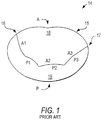
- FIG. 1 illustrates a normal mitral heart valve 14 from the left atrium from a surgical view of the heart.
- the anterior portion A of the mitral annulus 15 forms a part of the "cardiac skeleton" and is bounded by anterior and posterior commissures 16, 17.
- the anterior commissure 16 and posterior commissure 17 are generally at the junction points of the anterior leaflet 18 and the posterior leaflet 19.
- the junction points are also known as the anterolateral commissure 16 and posteromedial commissure 17.
- the posterior portion P of the mitral annulus 15 consists mainly of muscular tissue of the outer wall of the heart.
- posterior leaflet 19 is divided into three scallops indicated as P1, P2, and P3 in sequence from the anterior commissure 16 counterclockwise to the posterior commissure 17.
- Anterior leaflet 18 is also divided into three areas indicated as A1, A2, and A3 in sequence from the anterior commissure 16 clockwise to the posterior commissure 17.
- Ischemic heart disease can cause a mitral valve to become incompetent.
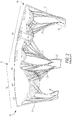
- regions of the left ventricle lose their contractility and dilate.
- the left ventricle enlarges and becomes more round in shape, going from a conical shape to more of a spherical shape.
- papillary muscles 23, 25 are displaced down (inferiorly) and away from each other. The change in the location of the papillary muscles increases the distance between the papillary muscles and the mitral valve annulus.
- chordae tendonae 21 that connect the posterior papillary muscle 23 to the mitral valve leaflets in the A2, A3, P2, and P3 regions of the annulus. Since the chordae tendonae 21 do not change their length significantly, the chordae 21 tend to pull or "tether" the mitral leaflets. In severe cases of left ventricle dilation, the tethering of the chordae prevents the leaflets from coming together or coapting correctly, resulting in mitral valve regurgitation. In addition to remodeling of the left ventricle, the mitral valve tends to flatten during ventricular systole instead of achieving its natural saddle shape. This also disrupts the natural coaptation of the mitral leaflets and the natural distribution of stresses over the leaflets and chordae tendonae.
- IMR ischemic mitral regurgitation
- the entire circumference of the mitral annulus may dilate.
- the posterior portion of the annulus may dilate more than the anterior portion because the anterior portion has more support from the heart's fibrous skeleton.
- the IMR may be caused by tethering of leaflet segments connected to the posteromedial papillary muscle. This is often in the A2, A3, P2, and P3 segments of the mitral valve.
- this type of mitral valve regurgitation is surgically repaired with an annuloplasty ring (which may be either a complete ring or a C-shaped "ring" with an opening along the anterior side).
- the repair restores proper leaflet coaptation by decreasing the diameter of the mitral valve annulus, thereby mitigating the effect of the tethering of the chordae and the effects of dilation of the annulus.
- One surgical correction for IMR is to tether the posteromedial annulus of the mitral valve to the posteromedial papillary muscle. This papillary muscle relocation procedure reduces the chordal tension and allows the leaflets to coapt more effectively.
- patient conditions like those described above are treated by applying an annuloplasty prosthesis (ring or C) that is shaped to push down the mitral valve annulus in the vicinity of the posterior commissure relative to other portions of the annulus.
- the prosthesis also dips down adjacent the anterior commissure, but it pushes down the portion of the annulus that is adjacent the posterior commissure farther than it dips down adjacent the anterior commissure.
- the effect of the prosthesis on the two commissure regions of the annulus is therefore asymmetrical.
- a mitral valve annuloplasty ring in accordance with the invention includes A1, A2, A3, P3, P2, and P1 segments connected to one another in a closed loop series in the order just mentioned. Each of these ring segments is configured for placement adjacent the portion of a mitral valve annulus that is adjacent the corresponding A1, A2, A3, P3, P2, or P1 segment of the mitral valve leaflets.
- the ring has an anterior-to-posterior ("AP") axis that extends across the ring from its anterior (A1/A2/A3) side to its posterior (P1/P2/P3) side.
- the AP axis is perpendicular to a line between two reference points that are spaced from one another along the anterior side of the ring.
- the AP axis also bisects this line.
- a third reference point is located along the posterior side of the ring to one side of the AP axis (e.g., the side that is toward or closer to the anterior commissure).
- Each of the above-mentioned three reference points is spaced from the AP axis by 0.5mm. These three reference points lie in and thereby define a reference plane.
- a point on the ring between the A1 and P1 segments, and another point on the ring between the A3 and P3 segments are both displaced from the reference plane to the same side of that plane. The amount of displacement from the reference plane to the point between the A3 and P3 segments is greater than the amount of displacement from the reference plane to the point between the A1 and P1 segments.
- an annuloplasty prosthesis in accordance with the invention may have a C shape.
- This C shape can be similar to a complete ring in accordance with the invention, but with a portion of the anterior side of the ring omitted.
- the gap in the C that results from this omission is generally located approximately centrally on the anterior side of the C structure.
- the anterior side of the C may be thought of as defining a trajectory that includes both the anterior structure (i.e., comparable to at least portions of the A1 and A3 segments of a comparable ring) and a smooth continuation, across the gap, of both of those anterior structural segments.
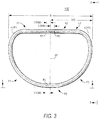
- FIGS. 3-5 An illustrative embodiment of a mitral valve annuloplasty ring 100, in accordance with the invention, that is better suited to treating patient conditions like those described in the background section of this specification is shown in FIGS. 3-5 .
- FIG. 3 shows ring 100 in the same orientation as FIG. 1 shows a mitral valve to which ring 100 may be applied.
- FIG. 3 shows that ring 100 has a generally D shape.
- the relatively straight side of the D (toward the top in FIG. 3 ) is the anterior side of the ring in use.
- the curved side of the D (toward the bottom in FIG. 3 ) is the posterior side of the ring in use.
- ring 100 includes anterior segments A1, A2, and A3, and posterior segments P1, P2, and P3. Each of these segments is radially adjacent but beyond or outside the corresponding portion of the mitral valve leaflets when the ring is in use (i.e., implanted in a patient adjacent the annulus of the patient's mitral valve).
- anterior ring segment A1 will be adjacent the base of the A1 segment of anterior leaflet 18 when ring 100 is in use.
- posterior ring segment P1 will be adjacent the base of the P1 segment of posterior leaflet 19 when ring 100 is in use.
- the same correspondence between ring segments and leaflet segments applies to all ring segments all the way around ring 100.
- ring 100 includes a closed loop series of segments A1, A2, A3, P3, P2, and P1, in that order.
- each of these reference points is located on an axis that runs annularly around the ring and that passes coaxially through the center of the core material of the ring.
- the point A3/P3 is the point at which ring segments A3 and P3 join or meet one another. This point is adjacent the posterior commissure 17 ( FIG. 1 ) of the mitral valve when ring 100 is in use. (The exact location of point A3/P3 along the ring is not critical. FIG. 3 thus tends to show the approximate locations of the various ring segments and points like A3/P3 and A1/P1. The locations of these features are, of course, generally as shown in FIG. 3 .)
- point A1/P1 Another significant point on ring 100 is point A1/P1. This is the point at which segments A1 and P1 join or meet one another. When ring 100 is in use, point A1/P1 is adjacent the anterior commissure 16 ( FIG. 1 ) of the mitral valve.
- Ring 100 has a so-called anterior-posterior ("AP") axis, which extends across the ring from its anterior side to its posterior side.
- the AP axis is located so that it is perpendicular to and bisects a line between reference points R1 and R2.
- Reference points R1 and R2 are located along the anterior side of the ring so that the AP axis bisects a greatest width dimension W of the ring, which greatest width dimension is measured perpendicular to the AP axis.
- Anterior-side reference point R1 is spaced to one side of the AP axis by 0.5mm.
- Anterior-side reference point R2 is spaced to the other side of the AP axis by 0.5mm.
- Reference point R3 is on the posterior side of the ring and is spaced to one side (e.g., the R1 side) of the AP axis by 0.5mm.
- Reference points R1-R3 lie in and thereby define the location of a so-called reference plane.
- the "greatest width dimension” W is the perpendicular distance between two tangents to the ring that are both parallel to the AP axis and that are as far apart as possible on opposite sides of the ring. It is possible that there may be some distance across the ring, measured in some other way, that is greater than W, but that is irrelevant to the present invention and not what is meant by the "greatest width dimension” as used herein.)
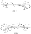
- FIG. 4 shows that ring 100 is not planar.
- each of anterior ring segments A1, A2, and A3 is substantially out of sight behind the corresponding posterior ring segment P1, P2, and P3 in FIG. 4 .
- the reference plane referred to in the preceding paragraph is identified in FIG. 4 (and FIG. 5 ) by the reference number 110.
- FIG. 4 shows ring segments A1 and P1 curving down and away from reference plane 110 as one proceeds to the left from a medial portion of what is visible in FIG. 4.
- FIG. 4 also shows ring segments A3 and P3 curving down and away from plane 110 as one proceeds to the right from the medial portion of FIG. 4 .
- points A1/P1 and A3/P3 are not per se visible in FIG. 4 , their approximate left-right locations are indicated with arrows labeled A1/P1 and A3/P3, respectively. It will be apparent from this depiction that point A3/P3 is lower relative to plane 110 than point A1/P1. Thus dimension D3 (the distance of point A3/P3 below plane 110) is greater than dimension D1 (the distance of point A1/P1 below plane 110). Ring 100 is thus asymmetrical from left to right (as viewed in FIG. 4 ) in this respect.
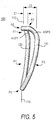
- FIG. 5 shows another view of ring 100 on an even larger scale than FIGS. 3 and 4 (see FIG. 3 for the orientation of FIG. 5 relative to FIGS. 3 and 4 ).
- FIG. 5 shows all the features of ring 100 that have been previously described.
- FIG. 5 again shows that the side of ring 100 that includes point A3/P3 is displaced farther from plane 110 than the side of the ring that includes point A1/P1. This is again shown in FIG. 5 by the fact that dimension D3 is greater than dimension D1.
- the displacement at point A1/P1 from reference plane 110 is not necessarily the greatest displacement of that side of the ring from that plane.
- Another point (like 120 in FIG. 5 ) along P1 may actually have greater displacement from plane 110 than point A1/P1.
- point A3/P3 may not have that side's greatest displacement from plane 110.
- Another point 130 along P3 may have even greater displacement from plane 110. Nevertheless, it remains the case that point A3/P3 has greater displacement (D3) from plane 110 than point A1/P1 has.
- Local maximum displacement point 130 (if different from point A3/P3, as it is in ring 100) also has greater displacement from plane 110 than local maximum displacement point 120 (again assumed to be different than point A1/P1, as in ring 100).
- point A3/P3 is also has greater displacement from plane 110 than any point (even point 120) on the other side of the ring.
- Ring 100 It will also be noted from what has been shown and described about ring 100 that, at a minimum, at least some portions of ring segments A3 and P3 curve, slope, or incline away from reference plane 110 (in the direction away from ring segments A2 and P2) in order for point A3/P3 to be displaced from that plane. Similarly, at least some portions of ring segments A1 and P1 curve, slope, or incline away from plane 110 (in the direction away from ring segments A2 and P2) in order for point A1/P1 to be displaced from that plane. Both the A1/P1 side of the ring and the A3/P3 side of the ring are displaced to the same side of plane 110. Ring 100 is thus saddle shaped.
- the displacement from plane 110 that is reached on the A3/P3 side of the ring is greater than the displacement that is reached on the A1/P1 side of the ring.
- the above-mentioned saddle shape is thus somewhat asymmetrical, with the A3/P3 side of the ring being more depressed than the A1/P1 side of the ring.
- the greater "downward" displacement of the side of ring 100 that includes point A3/P3 is of significant benefit in compensating for patient conditions like those described in the background section of this specification. Those conditions tend to downwardly displace tissue structures 23 (and their associated structures 21) more than tissue structures 25 (and their associated structures 21) (see again FIG. 2 ). Extra downward depression of the mitral valve annulus radially out from leaflet segments A3 and P3 (and including posterior commissure 17) may beneficially compensate for this problem. Such extra downward depression of this portion of the valve annulus is provided by ring 100, which has greater displacement from plane 110 on its side that includes segments A3 and P3 and point A3/P3 than on its other side (i.e., its side that includes segments A1 and P1 and point A1/P1).
- mitral valve annuloplasty prostheses are not always complete rings like ring 100.
- a portion of the anterior side of what would otherwise be a complete ring can be omitted to produce a C-shaped prosthesis.
- Examples of such Cs are shown in FIGS. 6 and 7 .
- the C 200 in FIG. 6 has a relatively small gap 402 on the anterior side.
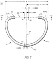
- the C 300 in FIG. 7 has a relatively large gap 402 on the anterior side.
- the anterior gap in FIG. 7 is approximately the maximum acceptable gap. Any amount of anterior-side gap (up to the approximate amount shown in FIG. 7 ) can be employed in C-shaped prostheses.
- the present invention can be applied to C-shaped prostheses like those exemplified by FIGS. 6 and 7 .
- the portions of such a C-shaped prosthesis that are present in the C are shaped and disposed in three dimensions as though they were the corresponding portions of a complete ring in accordance with the invention (see also FIG. 8 , which is another view of illustrative C shown in FIG. 7 ).
- a C-shaped prosthesis in accordance with the invention is shaped as though made from a complete ring in accordance with the invention, but with some of the anterior of the complete ring omitted to produce the C.
- trajectory 400 spans the entire anterior side of each C. Where the anterior side has structure or material (i.e., to the left and right of anterior gap 402), trajectory 400 passes coaxially and centrally along that structure. In gap 402 (where each C has no actual structure or material) trajectory 400 continues smoothly out of the material to one side of the gap, across the gap, and into the material on the other side of the gap. In other words, trajectory 402 follows the same path that the anterior side of the prosthesis 200 or 300 would have if it were a complete ring in accordance with the invention.
- FIGS. 6 and 7 show that the same reference points R1 through R3 that are descried above in connection with ring 100 can be used again to define a reference plane 410 (see FIG. 8 ) that is useful in describing the shape of Cs in accordance with the invention.
- reference points R1 and R2 are on anterior trajectory 400. This is so because, depending on the size of gap 402, reference points R1 and R2 may be either in anterior material of the C (e.g., as in the case of FIG. 6 ) or in the anterior gap 402 (e.g., as in the case of FIG. 7 ).
- the anterior trajectory concept makes it possible to describe the locations of reference points R1 and R2 generically, regardless of the size of gap 402.
- Cs in accordance with the invention e.g., a C like 200 or 300
- Cs in accordance with the invention (e.g., a C like 200 or 300) as including the following features: A1, P1, P2, P3, and A3 segments connected in series in that order; an anterior gap 402; an anterior trajectory 400 as described above; an anterior-to-posterior axis AP perpendicular to and bisecting a line between reference points R1 and R2, both of which are located along anterior trajectory 400; a greatest width dimension W measured perpendicular to the AP axis, reference points R1 and R2 and the AP axis being located so that the AP axis bisects the greatest width dimension; each of reference points R1 and R2 being spaced from the AP axis by 0.5mm; reference point R3 on the posterior side of the C, spaced to one side of the AP axis by 0.5mm, and defining with reference points R1 and R2 a reference plane 410; both of
- a wide range of materials are well known for making annuloplasty prostheses, and any of the known materials that are suitable for making prostheses in accordance with this invention can be used.
- suitable materials include titanium, a titanium alloy, Elgiloy (a cobalt-nickel alloy), Nitinol (a nickel-titanium alloy), stainless steel, a cobalt-chromium alloy, a ceramic, and a polymer (e.g., ultrahigh-molecular weight polyethylene, polyurethane, or the like).
- the prostheses of this invention (like ring 100 or Cs 200 or 300) can have any desired degree of rigidity, consistent with the objective of this invention for the prosthesis to apply significant forces in particular ways to various parts of the mitral valve annulus.
- the prostheses of this invention can be rigid or substantially rigid.
- the prostheses of this invention may be capable of some plastic deformation if the surgeon wants to modify the prosthesis shape somewhat for a particular patient's anatomy.
- the prosthesis should not be plastically deformable by the patient's anatomy alone, but the prosthesis may be capable of some elastic deformation in response to the patient's anatomy, including changes in anatomical shapes as a result of body functions such as heartbeats. Nevertheless, a prosthesis that is capable of such flexibility should always be resiliently trying to return to an unloaded shape like that shown in the FIGS. herein. In that way, even a prosthesis that is capable of some flexibility is always applying the kind of therapeutic force to the mitral valve annulus that is desired in accordance with the invention.
- the prostheses of this invention may also include other known annuloplasty prosthesis features.
- the prostheses of this invention may be wrapped in or otherwise associated with fabric or other materials through which sutures can be passed as part of the process of implanting the prosthesis in a patient.
Landscapes
- Health & Medical Sciences (AREA)
- Cardiology (AREA)
- Oral & Maxillofacial Surgery (AREA)
- Transplantation (AREA)
- Engineering & Computer Science (AREA)
- Biomedical Technology (AREA)
- Heart & Thoracic Surgery (AREA)
- Vascular Medicine (AREA)
- Life Sciences & Earth Sciences (AREA)
- Animal Behavior & Ethology (AREA)
- General Health & Medical Sciences (AREA)
- Public Health (AREA)
- Veterinary Medicine (AREA)
- Prostheses (AREA)
- Absorbent Articles And Supports Therefor (AREA)
Applications Claiming Priority (2)
| Application Number | Priority Date | Filing Date | Title |
|---|---|---|---|
| US73029705P | 2005-10-26 | 2005-10-26 | |
| PCT/US2006/041272 WO2007050506A1 (en) | 2005-10-26 | 2006-10-24 | Saddle-shaped mitral valve annuloplasty prostheses with asymmetry, and related methods |
Publications (2)
| Publication Number | Publication Date |
|---|---|
| EP1951154A1 EP1951154A1 (en) | 2008-08-06 |
| EP1951154B1 true EP1951154B1 (en) | 2018-01-24 |
Family
ID=37745955
Family Applications (1)
| Application Number | Title | Priority Date | Filing Date |
|---|---|---|---|
| EP06836458.7A Not-in-force EP1951154B1 (en) | 2005-10-26 | 2006-10-24 | Saddle-shaped mitral valve annuloplasty prostheses |
Country Status (5)
| Country | Link |
|---|---|
| US (2) | US20070100441A1 (enExample) |
| EP (1) | EP1951154B1 (enExample) |
| JP (1) | JP4820875B2 (enExample) |
| ES (1) | ES2660164T3 (enExample) |
| WO (1) | WO2007050506A1 (enExample) |
Cited By (15)
| Publication number | Priority date | Publication date | Assignee | Title |
|---|---|---|---|---|
| US10856984B2 (en) | 2017-08-25 | 2020-12-08 | Neovasc Tiara Inc. | Sequentially deployed transcatheter mitral valve prosthesis |
| US10940001B2 (en) | 2012-05-30 | 2021-03-09 | Neovasc Tiara Inc. | Methods and apparatus for loading a prosthesis onto a delivery system |
| US11311376B2 (en) | 2019-06-20 | 2022-04-26 | Neovase Tiara Inc. | Low profile prosthetic mitral valve |
| US11357622B2 (en) | 2016-01-29 | 2022-06-14 | Neovase Tiara Inc. | Prosthetic valve for avoiding obstruction of outflow |
| US11389291B2 (en) | 2013-04-04 | 2022-07-19 | Neovase Tiara Inc. | Methods and apparatus for delivering a prosthetic valve to a beating heart |
| US11413139B2 (en) | 2011-11-23 | 2022-08-16 | Neovasc Tiara Inc. | Sequentially deployed transcatheter mitral valve prosthesis |
| US11419720B2 (en) | 2010-05-05 | 2022-08-23 | Neovasc Tiara Inc. | Transcatheter mitral valve prosthesis |
| US11464631B2 (en) | 2016-11-21 | 2022-10-11 | Neovasc Tiara Inc. | Methods and systems for rapid retraction of a transcatheter heart valve delivery system |
| US11491006B2 (en) | 2019-04-10 | 2022-11-08 | Neovasc Tiara Inc. | Prosthetic valve with natural blood flow |
| US11497602B2 (en) | 2012-02-14 | 2022-11-15 | Neovasc Tiara Inc. | Methods and apparatus for engaging a valve prosthesis with tissue |
| US11602429B2 (en) | 2019-04-01 | 2023-03-14 | Neovasc Tiara Inc. | Controllably deployable prosthetic valve |
| US11737872B2 (en) | 2018-11-08 | 2023-08-29 | Neovasc Tiara Inc. | Ventricular deployment of a transcatheter mitral valve prosthesis |
| US11779742B2 (en) | 2019-05-20 | 2023-10-10 | Neovasc Tiara Inc. | Introducer with hemostasis mechanism |
| US11998447B2 (en) | 2019-03-08 | 2024-06-04 | Neovasc Tiara Inc. | Retrievable prosthesis delivery system |
| US12109111B2 (en) | 2015-12-15 | 2024-10-08 | Neovasc Tiara Inc. | Transseptal delivery system |
Families Citing this family (42)
| Publication number | Priority date | Publication date | Assignee | Title |
|---|---|---|---|---|
| US6736845B2 (en) * | 1999-01-26 | 2004-05-18 | Edwards Lifesciences Corporation | Holder for flexible heart valve |
| ITMI20011012A1 (it) | 2001-05-17 | 2002-11-17 | Ottavio Alfieri | Protesi anulare per valvola mitrale |
| US7935145B2 (en) | 2001-05-17 | 2011-05-03 | Edwards Lifesciences Corporation | Annuloplasty ring for ischemic mitral valve insuffuciency |
| US6908482B2 (en) | 2001-08-28 | 2005-06-21 | Edwards Lifesciences Corporation | Three-dimensional annuloplasty ring and template |
| US7367991B2 (en) | 2001-08-28 | 2008-05-06 | Edwards Lifesciences Corporation | Conformal tricuspid annuloplasty ring and template |
| US7951196B2 (en) * | 2004-04-29 | 2011-05-31 | Edwards Lifesciences Corporation | Annuloplasty ring for mitral valve prolapse |
| US7575595B2 (en) | 2005-03-23 | 2009-08-18 | Edwards Lifesciences Corporation | Annuloplasty ring and holder combination |
| US7842085B2 (en) | 2005-03-23 | 2010-11-30 | Vaso Adzich | Annuloplasty ring and holder combination |
| CA2669195C (en) | 2005-12-15 | 2013-06-25 | Georgia Tech Research Corporation | Systems and methods to control the dimension of a heart valve |
| WO2007100408A2 (en) | 2005-12-15 | 2007-09-07 | Georgia Tech Research Corporation | Papillary muscle position control devices, systems & methods |
| US8568473B2 (en) | 2005-12-15 | 2013-10-29 | Georgia Tech Research Corporation | Systems and methods for enabling heart valve replacement |
| EP1820482A1 (en) | 2006-02-17 | 2007-08-22 | The Procter & Gamble Company | Diaper closure elements |
| ATE499074T1 (de) | 2006-05-15 | 2011-03-15 | Edwards Lifesciences Ag | System zur veränderung der geometrie des herzens |
| CA2653358C (en) * | 2006-06-02 | 2012-03-13 | Medtronic, Inc. | Annuloplasty ring and method |
| EP2032079B1 (en) | 2006-06-02 | 2015-08-12 | Medtronic, Inc. | Annuloplasty prosthesis with in vivo shape identification |
| CA2661317A1 (en) | 2006-08-24 | 2008-02-28 | Global Valve Technology Limited | Centreline flow valve |
| US20080058924A1 (en) * | 2006-09-01 | 2008-03-06 | Aaron Ingle | Saddle-shaped annuloplasty ring |
| US7879087B2 (en) * | 2006-10-06 | 2011-02-01 | Edwards Lifesciences Corporation | Mitral and tricuspid annuloplasty rings |
| WO2008098226A1 (en) | 2007-02-09 | 2008-08-14 | Edwards Lifesciences Corporation | Progressively sized annuloplasty rings |
| US8529620B2 (en) * | 2007-05-01 | 2013-09-10 | Ottavio Alfieri | Inwardly-bowed tricuspid annuloplasty ring |
| CA2698388C (en) | 2007-09-07 | 2015-11-24 | Edwards Lifesciences Corporation | Active holder for annuloplasty ring delivery |
| US8784483B2 (en) * | 2007-11-19 | 2014-07-22 | The Cleveland Clinic Foundation | Apparatus and method for treating a regurgitant heart valve |
| US7993395B2 (en) * | 2008-01-25 | 2011-08-09 | Medtronic, Inc. | Set of annuloplasty devices with varying anterior-posterior ratios and related methods |
| US20090287303A1 (en) | 2008-05-13 | 2009-11-19 | Edwards Lifesciences Corporation | Physiologically harmonized tricuspid annuloplasty ring |
| US9314335B2 (en) | 2008-09-19 | 2016-04-19 | Edwards Lifesciences Corporation | Prosthetic heart valve configured to receive a percutaneous prosthetic heart valve implantation |
| WO2010033936A2 (en) * | 2008-09-19 | 2010-03-25 | Edwards Lifesciences Corporation | Annuloplasty ring configured to receive a percutaneous prosthetic heart valve implantation |
| US8287591B2 (en) * | 2008-09-19 | 2012-10-16 | Edwards Lifesciences Corporation | Transformable annuloplasty ring configured to receive a percutaneous prosthetic heart valve implantation |
| US8163012B2 (en) * | 2009-01-13 | 2012-04-24 | Hosam Fouad Fawzy | Multi-planar tricuspid annuloplasty ring |
| US20110160849A1 (en) * | 2009-12-22 | 2011-06-30 | Edwards Lifesciences Corporation | Bimodal tricuspid annuloplasty ring |
| US20130150958A1 (en) * | 2010-08-02 | 2013-06-13 | Ruggero De Paulis | Annuloplasty band for a simplified approach to mitral valvuloplasty for degenerative diseases |
| CA2808885C (en) | 2010-08-24 | 2017-01-10 | John F. Migliazza | Flexible annuloplasty ring with select control points |
| CN103189016B (zh) | 2010-08-31 | 2016-08-10 | 爱德华兹生命科学公司 | 生理性三尖瓣瓣膜成形环 |
| US8932350B2 (en) | 2010-11-30 | 2015-01-13 | Edwards Lifesciences Corporation | Reduced dehiscence annuloplasty ring |
| CN104884002B (zh) | 2012-12-31 | 2017-04-05 | 爱德华兹生命科学公司 | 适于植入后扩张的外科心脏瓣膜 |
| US10543085B2 (en) | 2012-12-31 | 2020-01-28 | Edwards Lifesciences Corporation | One-piece heart valve stents adapted for post-implant expansion |
| US9687346B2 (en) | 2013-03-14 | 2017-06-27 | Edwards Lifesciences Corporation | Multi-stranded heat set annuloplasty rings |
| US10314707B2 (en) * | 2015-06-09 | 2019-06-11 | Edwards Lifesciences, Llc | Asymmetric mitral annuloplasty band |
| US10695170B2 (en) | 2015-07-02 | 2020-06-30 | Edwards Lifesciences Corporation | Hybrid heart valves adapted for post-implant expansion |
| US10456246B2 (en) | 2015-07-02 | 2019-10-29 | Edwards Lifesciences Corporation | Integrated hybrid heart valves |
| GB2548891B (en) | 2016-03-31 | 2018-07-04 | I Birdi Ltd | A prosthetic device for mitral valve repair |
| USD944398S1 (en) | 2018-06-13 | 2022-02-22 | Edwards Lifesciences Corporation | Expanded heart valve stent |
| CA3104687A1 (en) | 2018-07-30 | 2020-02-06 | Edwards Lifesciences Corporation | Minimally-invasive low strain annuloplasty ring |
Family Cites Families (17)
| Publication number | Priority date | Publication date | Assignee | Title |
|---|---|---|---|---|
| WO1990009153A1 (en) | 1989-02-13 | 1990-08-23 | Baxter International Inc. | Selectively flexible annuloplasty ring |
| US6217610B1 (en) | 1994-07-29 | 2001-04-17 | Edwards Lifesciences Corporation | Expandable annuloplasty ring |
| EP0860151A1 (en) | 1997-02-25 | 1998-08-26 | Naqeeb Khalid | Cardiac valvular support prosthesis |
| DE19910233A1 (de) * | 1999-03-09 | 2000-09-21 | Jostra Medizintechnik Ag | Anuloplastieprothese |
| US6797002B2 (en) * | 2000-02-02 | 2004-09-28 | Paul A. Spence | Heart valve repair apparatus and methods |
| US7935145B2 (en) * | 2001-05-17 | 2011-05-03 | Edwards Lifesciences Corporation | Annuloplasty ring for ischemic mitral valve insuffuciency |
| US6858039B2 (en) * | 2002-07-08 | 2005-02-22 | Edwards Lifesciences Corporation | Mitral valve annuloplasty ring having a posterior bow |
| ITMI20011012A1 (it) * | 2001-05-17 | 2002-11-17 | Ottavio Alfieri | Protesi anulare per valvola mitrale |
| US6908482B2 (en) * | 2001-08-28 | 2005-06-21 | Edwards Lifesciences Corporation | Three-dimensional annuloplasty ring and template |
| US6805710B2 (en) | 2001-11-13 | 2004-10-19 | Edwards Lifesciences Corporation | Mitral valve annuloplasty ring for molding left ventricle geometry |
| AU2004279391A1 (en) * | 2003-10-03 | 2005-04-21 | Edwards Lifesciences Corporation | Annuloplasty rings for repair of abnormal mitral valves |
| US7938856B2 (en) * | 2004-05-14 | 2011-05-10 | St. Jude Medical, Inc. | Heart valve annuloplasty prosthesis sewing cuffs and methods of making same |
| US20050256568A1 (en) * | 2004-05-14 | 2005-11-17 | St. Jude Medical, Inc. | C-shaped heart valve prostheses |
| US7452376B2 (en) * | 2004-05-14 | 2008-11-18 | St. Jude Medical, Inc. | Flexible, non-planar annuloplasty rings |
| WO2005112832A1 (en) * | 2004-05-14 | 2005-12-01 | St. Jude Medical, Inc. | Systems and methods for holding annuloplasty rings |
| US20050278022A1 (en) * | 2004-06-14 | 2005-12-15 | St. Jude Medical, Inc. | Annuloplasty prostheses with improved anchoring structures, and related methods |
| US20060100697A1 (en) * | 2004-11-10 | 2006-05-11 | Casanova R M | Shape memory annuloplasty ring and holder |
-
2006
- 2006-10-24 US US11/585,483 patent/US20070100441A1/en not_active Abandoned
- 2006-10-24 ES ES06836458.7T patent/ES2660164T3/es active Active
- 2006-10-24 WO PCT/US2006/041272 patent/WO2007050506A1/en not_active Ceased
- 2006-10-24 EP EP06836458.7A patent/EP1951154B1/en not_active Not-in-force
- 2006-10-24 JP JP2008537839A patent/JP4820875B2/ja not_active Expired - Fee Related
-
2010
- 2010-08-27 US US12/870,252 patent/US8123802B2/en not_active Expired - Fee Related
Cited By (24)
| Publication number | Priority date | Publication date | Assignee | Title |
|---|---|---|---|---|
| US11419720B2 (en) | 2010-05-05 | 2022-08-23 | Neovasc Tiara Inc. | Transcatheter mitral valve prosthesis |
| US11413139B2 (en) | 2011-11-23 | 2022-08-16 | Neovasc Tiara Inc. | Sequentially deployed transcatheter mitral valve prosthesis |
| US12053369B2 (en) | 2011-11-23 | 2024-08-06 | Neovasc Tiara Inc. | Sequentially deployed transcatheter mitral valve prosthesis |
| US12138159B2 (en) | 2012-02-14 | 2024-11-12 | Neovasc Tiara Inc. | Methods and apparatus for engaging a valve prosthesis with tissue |
| US11497602B2 (en) | 2012-02-14 | 2022-11-15 | Neovasc Tiara Inc. | Methods and apparatus for engaging a valve prosthesis with tissue |
| US11617650B2 (en) | 2012-05-30 | 2023-04-04 | Neovasc Tiara Inc. | Methods and apparatus for loading a prosthesis onto a delivery system |
| US11389294B2 (en) | 2012-05-30 | 2022-07-19 | Neovasc Tiara Inc. | Methods and apparatus for loading a prosthesis onto a delivery system |
| US10940001B2 (en) | 2012-05-30 | 2021-03-09 | Neovasc Tiara Inc. | Methods and apparatus for loading a prosthesis onto a delivery system |
| US11389291B2 (en) | 2013-04-04 | 2022-07-19 | Neovase Tiara Inc. | Methods and apparatus for delivering a prosthetic valve to a beating heart |
| US12109111B2 (en) | 2015-12-15 | 2024-10-08 | Neovasc Tiara Inc. | Transseptal delivery system |
| US12193932B2 (en) | 2016-01-29 | 2025-01-14 | Neovasc Tiara Inc. | Prosthetic valve for avoiding obstruction of outflow |
| US11357622B2 (en) | 2016-01-29 | 2022-06-14 | Neovase Tiara Inc. | Prosthetic valve for avoiding obstruction of outflow |
| US11464631B2 (en) | 2016-11-21 | 2022-10-11 | Neovasc Tiara Inc. | Methods and systems for rapid retraction of a transcatheter heart valve delivery system |
| US12201524B2 (en) | 2016-11-21 | 2025-01-21 | Neovasc Tiara Inc. | Methods and systems for rapid retraction of a transcatheter heart valve delivery system |
| US10856984B2 (en) | 2017-08-25 | 2020-12-08 | Neovasc Tiara Inc. | Sequentially deployed transcatheter mitral valve prosthesis |
| US11793640B2 (en) | 2017-08-25 | 2023-10-24 | Neovasc Tiara Inc. | Sequentially deployed transcatheter mitral valve prosthesis |
| US11737872B2 (en) | 2018-11-08 | 2023-08-29 | Neovasc Tiara Inc. | Ventricular deployment of a transcatheter mitral valve prosthesis |
| US11998447B2 (en) | 2019-03-08 | 2024-06-04 | Neovasc Tiara Inc. | Retrievable prosthesis delivery system |
| US11602429B2 (en) | 2019-04-01 | 2023-03-14 | Neovasc Tiara Inc. | Controllably deployable prosthetic valve |
| US12036117B2 (en) | 2019-04-10 | 2024-07-16 | Neovasc Tiara Inc. | Prosthetic valve with natural blood flow |
| US11491006B2 (en) | 2019-04-10 | 2022-11-08 | Neovasc Tiara Inc. | Prosthetic valve with natural blood flow |
| US11779742B2 (en) | 2019-05-20 | 2023-10-10 | Neovasc Tiara Inc. | Introducer with hemostasis mechanism |
| US11311376B2 (en) | 2019-06-20 | 2022-04-26 | Neovase Tiara Inc. | Low profile prosthetic mitral valve |
| US11931254B2 (en) | 2019-06-20 | 2024-03-19 | Neovasc Tiara Inc. | Low profile prosthetic mitral valve |
Also Published As
| Publication number | Publication date |
|---|---|
| EP1951154A1 (en) | 2008-08-06 |
| JP2009513253A (ja) | 2009-04-02 |
| US20070100441A1 (en) | 2007-05-03 |
| ES2660164T3 (es) | 2018-03-21 |
| JP4820875B2 (ja) | 2011-11-24 |
| US20100324670A1 (en) | 2010-12-23 |
| WO2007050506A1 (en) | 2007-05-03 |
| US8123802B2 (en) | 2012-02-28 |
Similar Documents
| Publication | Publication Date | Title |
|---|---|---|
| EP1951154B1 (en) | Saddle-shaped mitral valve annuloplasty prostheses | |
| US11903830B2 (en) | Physiologically harmonized repair of tricuspid valve | |
| JP7765424B2 (ja) | 非対称な僧帽弁形成バンド | |
| US10166101B2 (en) | Methods for repairing mitral valves | |
| EP2142144B1 (en) | Inwardly-bowed tricuspid annuloplasty ring | |
| EP2249745B1 (en) | Set of annuloplasty devices with varying anterior-posterior ratios | |
| CA2539459C (en) | Annuloplasty rings for repair of abnormal mitral valves | |
| US20110238171A1 (en) | Mitral annuloplasty rings with sewing cuff |
Legal Events
| Date | Code | Title | Description |
|---|---|---|---|
| PUAI | Public reference made under article 153(3) epc to a published international application that has entered the european phase |
Free format text: ORIGINAL CODE: 0009012 |
|
| 17P | Request for examination filed |
Effective date: 20080507 |
|
| AK | Designated contracting states |
Kind code of ref document: A1 Designated state(s): AT BE BG CH CY CZ DE DK EE ES FI FR GB GR HU IE IS IT LI LT LU LV MC NL PL PT RO SE SI SK TR |
|
| DAX | Request for extension of the european patent (deleted) | ||
| 17Q | First examination report despatched |
Effective date: 20131115 |
|
| GRAP | Despatch of communication of intention to grant a patent |
Free format text: ORIGINAL CODE: EPIDOSNIGR1 |
|
| RIN1 | Information on inventor provided before grant (corrected) |
Inventor name: MCGILL, TIMOTHY J. Inventor name: KOVACH, MELINDA K. Inventor name: KRON, IRVING L. Inventor name: ZENZ-OLSON, NATHANIAL Z. |
|
| INTG | Intention to grant announced |
Effective date: 20170911 |
|
| RAP1 | Party data changed (applicant data changed or rights of an application transferred) |
Owner name: ST. JUDE MEDICAL, INC. |
|
| GRAS | Grant fee paid |
Free format text: ORIGINAL CODE: EPIDOSNIGR3 |
|
| GRAA | (expected) grant |
Free format text: ORIGINAL CODE: 0009210 |
|
| AK | Designated contracting states |
Kind code of ref document: B1 Designated state(s): AT BE BG CH CY CZ DE DK EE ES FI FR GB GR HU IE IS IT LI LT LU LV MC NL PL PT RO SE SI SK TR |
|
| REG | Reference to a national code |
Ref country code: GB Ref legal event code: FG4D |
|
| REG | Reference to a national code |
Ref country code: CH Ref legal event code: EP |
|
| REG | Reference to a national code |
Ref country code: AT Ref legal event code: REF Ref document number: 965333 Country of ref document: AT Kind code of ref document: T Effective date: 20180215 |
|
| REG | Reference to a national code |
Ref country code: IE Ref legal event code: FG4D |
|
| REG | Reference to a national code |
Ref country code: DE Ref legal event code: R096 Ref document number: 602006054626 Country of ref document: DE |
|
| REG | Reference to a national code |
Ref country code: ES Ref legal event code: FG2A Ref document number: 2660164 Country of ref document: ES Kind code of ref document: T3 Effective date: 20180321 |
|
| REG | Reference to a national code |
Ref country code: NL Ref legal event code: MP Effective date: 20180124 |
|
| REG | Reference to a national code |
Ref country code: LT Ref legal event code: MG4D |
|
| REG | Reference to a national code |
Ref country code: AT Ref legal event code: MK05 Ref document number: 965333 Country of ref document: AT Kind code of ref document: T Effective date: 20180124 |
|
| PG25 | Lapsed in a contracting state [announced via postgrant information from national office to epo] |
Ref country code: NL Free format text: LAPSE BECAUSE OF FAILURE TO SUBMIT A TRANSLATION OF THE DESCRIPTION OR TO PAY THE FEE WITHIN THE PRESCRIBED TIME-LIMIT Effective date: 20180124 |
|
| PG25 | Lapsed in a contracting state [announced via postgrant information from national office to epo] |
Ref country code: LT Free format text: LAPSE BECAUSE OF FAILURE TO SUBMIT A TRANSLATION OF THE DESCRIPTION OR TO PAY THE FEE WITHIN THE PRESCRIBED TIME-LIMIT Effective date: 20180124 Ref country code: CY Free format text: LAPSE BECAUSE OF FAILURE TO SUBMIT A TRANSLATION OF THE DESCRIPTION OR TO PAY THE FEE WITHIN THE PRESCRIBED TIME-LIMIT Effective date: 20180124 Ref country code: FI Free format text: LAPSE BECAUSE OF FAILURE TO SUBMIT A TRANSLATION OF THE DESCRIPTION OR TO PAY THE FEE WITHIN THE PRESCRIBED TIME-LIMIT Effective date: 20180124 |
|
| PG25 | Lapsed in a contracting state [announced via postgrant information from national office to epo] |
Ref country code: BG Free format text: LAPSE BECAUSE OF FAILURE TO SUBMIT A TRANSLATION OF THE DESCRIPTION OR TO PAY THE FEE WITHIN THE PRESCRIBED TIME-LIMIT Effective date: 20180424 Ref country code: GR Free format text: LAPSE BECAUSE OF FAILURE TO SUBMIT A TRANSLATION OF THE DESCRIPTION OR TO PAY THE FEE WITHIN THE PRESCRIBED TIME-LIMIT Effective date: 20180425 Ref country code: PL Free format text: LAPSE BECAUSE OF FAILURE TO SUBMIT A TRANSLATION OF THE DESCRIPTION OR TO PAY THE FEE WITHIN THE PRESCRIBED TIME-LIMIT Effective date: 20180124 Ref country code: SE Free format text: LAPSE BECAUSE OF FAILURE TO SUBMIT A TRANSLATION OF THE DESCRIPTION OR TO PAY THE FEE WITHIN THE PRESCRIBED TIME-LIMIT Effective date: 20180124 Ref country code: AT Free format text: LAPSE BECAUSE OF FAILURE TO SUBMIT A TRANSLATION OF THE DESCRIPTION OR TO PAY THE FEE WITHIN THE PRESCRIBED TIME-LIMIT Effective date: 20180124 Ref country code: LV Free format text: LAPSE BECAUSE OF FAILURE TO SUBMIT A TRANSLATION OF THE DESCRIPTION OR TO PAY THE FEE WITHIN THE PRESCRIBED TIME-LIMIT Effective date: 20180124 Ref country code: IS Free format text: LAPSE BECAUSE OF FAILURE TO SUBMIT A TRANSLATION OF THE DESCRIPTION OR TO PAY THE FEE WITHIN THE PRESCRIBED TIME-LIMIT Effective date: 20180524 |
|
| REG | Reference to a national code |
Ref country code: DE Ref legal event code: R097 Ref document number: 602006054626 Country of ref document: DE |
|
| PG25 | Lapsed in a contracting state [announced via postgrant information from national office to epo] |
Ref country code: EE Free format text: LAPSE BECAUSE OF FAILURE TO SUBMIT A TRANSLATION OF THE DESCRIPTION OR TO PAY THE FEE WITHIN THE PRESCRIBED TIME-LIMIT Effective date: 20180124 Ref country code: RO Free format text: LAPSE BECAUSE OF FAILURE TO SUBMIT A TRANSLATION OF THE DESCRIPTION OR TO PAY THE FEE WITHIN THE PRESCRIBED TIME-LIMIT Effective date: 20180124 |
|
| PG25 | Lapsed in a contracting state [announced via postgrant information from national office to epo] |
Ref country code: CZ Free format text: LAPSE BECAUSE OF FAILURE TO SUBMIT A TRANSLATION OF THE DESCRIPTION OR TO PAY THE FEE WITHIN THE PRESCRIBED TIME-LIMIT Effective date: 20180124 Ref country code: DK Free format text: LAPSE BECAUSE OF FAILURE TO SUBMIT A TRANSLATION OF THE DESCRIPTION OR TO PAY THE FEE WITHIN THE PRESCRIBED TIME-LIMIT Effective date: 20180124 Ref country code: SK Free format text: LAPSE BECAUSE OF FAILURE TO SUBMIT A TRANSLATION OF THE DESCRIPTION OR TO PAY THE FEE WITHIN THE PRESCRIBED TIME-LIMIT Effective date: 20180124 |
|
| PLBE | No opposition filed within time limit |
Free format text: ORIGINAL CODE: 0009261 |
|
| STAA | Information on the status of an ep patent application or granted ep patent |
Free format text: STATUS: NO OPPOSITION FILED WITHIN TIME LIMIT |
|
| 26N | No opposition filed |
Effective date: 20181025 |
|
| PG25 | Lapsed in a contracting state [announced via postgrant information from national office to epo] |
Ref country code: SI Free format text: LAPSE BECAUSE OF FAILURE TO SUBMIT A TRANSLATION OF THE DESCRIPTION OR TO PAY THE FEE WITHIN THE PRESCRIBED TIME-LIMIT Effective date: 20180124 |
|
| REG | Reference to a national code |
Ref country code: CH Ref legal event code: PL |
|
| REG | Reference to a national code |
Ref country code: BE Ref legal event code: MM Effective date: 20181031 |
|
| PG25 | Lapsed in a contracting state [announced via postgrant information from national office to epo] |
Ref country code: LU Free format text: LAPSE BECAUSE OF NON-PAYMENT OF DUE FEES Effective date: 20181024 Ref country code: MC Free format text: LAPSE BECAUSE OF FAILURE TO SUBMIT A TRANSLATION OF THE DESCRIPTION OR TO PAY THE FEE WITHIN THE PRESCRIBED TIME-LIMIT Effective date: 20180124 |
|
| REG | Reference to a national code |
Ref country code: IE Ref legal event code: MM4A |
|
| PG25 | Lapsed in a contracting state [announced via postgrant information from national office to epo] |
Ref country code: BE Free format text: LAPSE BECAUSE OF NON-PAYMENT OF DUE FEES Effective date: 20181031 Ref country code: FR Free format text: LAPSE BECAUSE OF NON-PAYMENT OF DUE FEES Effective date: 20181031 Ref country code: CH Free format text: LAPSE BECAUSE OF NON-PAYMENT OF DUE FEES Effective date: 20181031 Ref country code: LI Free format text: LAPSE BECAUSE OF NON-PAYMENT OF DUE FEES Effective date: 20181031 |
|
| PG25 | Lapsed in a contracting state [announced via postgrant information from national office to epo] |
Ref country code: IT Free format text: LAPSE BECAUSE OF NON-PAYMENT OF DUE FEES Effective date: 20181024 Ref country code: IE Free format text: LAPSE BECAUSE OF NON-PAYMENT OF DUE FEES Effective date: 20181024 |
|
| REG | Reference to a national code |
Ref country code: ES Ref legal event code: FD2A Effective date: 20191204 |
|
| PGFP | Annual fee paid to national office [announced via postgrant information from national office to epo] |
Ref country code: GB Payment date: 20190925 Year of fee payment: 14 |
|
| PGFP | Annual fee paid to national office [announced via postgrant information from national office to epo] |
Ref country code: DE Payment date: 20190917 Year of fee payment: 14 |
|
| PG25 | Lapsed in a contracting state [announced via postgrant information from national office to epo] |
Ref country code: ES Free format text: LAPSE BECAUSE OF NON-PAYMENT OF DUE FEES Effective date: 20181025 |
|
| PG25 | Lapsed in a contracting state [announced via postgrant information from national office to epo] |
Ref country code: TR Free format text: LAPSE BECAUSE OF FAILURE TO SUBMIT A TRANSLATION OF THE DESCRIPTION OR TO PAY THE FEE WITHIN THE PRESCRIBED TIME-LIMIT Effective date: 20180124 |
|
| PG25 | Lapsed in a contracting state [announced via postgrant information from national office to epo] |
Ref country code: PT Free format text: LAPSE BECAUSE OF FAILURE TO SUBMIT A TRANSLATION OF THE DESCRIPTION OR TO PAY THE FEE WITHIN THE PRESCRIBED TIME-LIMIT Effective date: 20180124 |
|
| PG25 | Lapsed in a contracting state [announced via postgrant information from national office to epo] |
Ref country code: HU Free format text: LAPSE BECAUSE OF FAILURE TO SUBMIT A TRANSLATION OF THE DESCRIPTION OR TO PAY THE FEE WITHIN THE PRESCRIBED TIME-LIMIT; INVALID AB INITIO Effective date: 20061024 |
|
| REG | Reference to a national code |
Ref country code: DE Ref legal event code: R119 Ref document number: 602006054626 Country of ref document: DE |
|
| GBPC | Gb: european patent ceased through non-payment of renewal fee |
Effective date: 20201024 |
|
| PG25 | Lapsed in a contracting state [announced via postgrant information from national office to epo] |
Ref country code: DE Free format text: LAPSE BECAUSE OF NON-PAYMENT OF DUE FEES Effective date: 20210501 |
|
| PG25 | Lapsed in a contracting state [announced via postgrant information from national office to epo] |
Ref country code: GB Free format text: LAPSE BECAUSE OF NON-PAYMENT OF DUE FEES Effective date: 20201024 |
|
| P01 | Opt-out of the competence of the unified patent court (upc) registered |
Effective date: 20230623 |