EP1951131B1 - Konturierte fräsenzähne und herstellungsverfahren - Google Patents
Konturierte fräsenzähne und herstellungsverfahren Download PDFInfo
- Publication number
- EP1951131B1 EP1951131B1 EP06809067A EP06809067A EP1951131B1 EP 1951131 B1 EP1951131 B1 EP 1951131B1 EP 06809067 A EP06809067 A EP 06809067A EP 06809067 A EP06809067 A EP 06809067A EP 1951131 B1 EP1951131 B1 EP 1951131B1
- Authority
- EP
- European Patent Office
- Prior art keywords
- cutting
- teeth
- reamer
- edge
- shell
- Prior art date
- Legal status (The legal status is an assumption and is not a legal conclusion. Google has not performed a legal analysis and makes no representation as to the accuracy of the status listed.)
- Active
Links
- 238000000034 method Methods 0.000 title claims abstract description 7
- 238000004519 manufacturing process Methods 0.000 title description 6
- 238000005520 cutting process Methods 0.000 claims abstract description 109
- 230000036346 tooth eruption Effects 0.000 claims abstract description 13
- 238000004080 punching Methods 0.000 claims description 3
- 210000000988 bone and bone Anatomy 0.000 description 5
- 230000008901 benefit Effects 0.000 description 4
- 239000007943 implant Substances 0.000 description 4
- 239000000463 material Substances 0.000 description 4
- 210000001624 hip Anatomy 0.000 description 3
- 210000004872 soft tissue Anatomy 0.000 description 3
- 210000000588 acetabulum Anatomy 0.000 description 2
- 230000020169 heat generation Effects 0.000 description 2
- 238000012986 modification Methods 0.000 description 2
- 230000004048 modification Effects 0.000 description 2
- 238000011084 recovery Methods 0.000 description 2
- 238000001356 surgical procedure Methods 0.000 description 2
- 238000010408 sweeping Methods 0.000 description 2
- 210000001519 tissue Anatomy 0.000 description 2
- 208000015375 Reduced number of teeth Diseases 0.000 description 1
- 238000013459 approach Methods 0.000 description 1
- 230000008859 change Effects 0.000 description 1
- 235000013351 cheese Nutrition 0.000 description 1
- 230000001010 compromised effect Effects 0.000 description 1
- 230000007423 decrease Effects 0.000 description 1
- 238000010586 diagram Methods 0.000 description 1
- 238000004512 die casting Methods 0.000 description 1
- 208000014674 injury Diseases 0.000 description 1
- 238000005495 investment casting Methods 0.000 description 1
- 230000001788 irregular Effects 0.000 description 1
- 230000007246 mechanism Effects 0.000 description 1
- 239000002184 metal Substances 0.000 description 1
- 230000035515 penetration Effects 0.000 description 1
- 238000005498 polishing Methods 0.000 description 1
- 238000012545 processing Methods 0.000 description 1
- 238000006467 substitution reaction Methods 0.000 description 1
- 238000012360 testing method Methods 0.000 description 1
- 230000007704 transition Effects 0.000 description 1
- 230000008733 trauma Effects 0.000 description 1
Images


Classifications
-
- A—HUMAN NECESSITIES
- A61—MEDICAL OR VETERINARY SCIENCE; HYGIENE
- A61B—DIAGNOSIS; SURGERY; IDENTIFICATION
- A61B17/00—Surgical instruments, devices or methods, e.g. tourniquets
- A61B17/16—Bone cutting, breaking or removal means other than saws, e.g. Osteoclasts; Drills or chisels for bones; Trepans
- A61B17/1662—Bone cutting, breaking or removal means other than saws, e.g. Osteoclasts; Drills or chisels for bones; Trepans for particular parts of the body
- A61B17/1664—Bone cutting, breaking or removal means other than saws, e.g. Osteoclasts; Drills or chisels for bones; Trepans for particular parts of the body for the hip
- A61B17/1666—Bone cutting, breaking or removal means other than saws, e.g. Osteoclasts; Drills or chisels for bones; Trepans for particular parts of the body for the hip for the acetabulum
Definitions
- the invention relates to surgical products, and in particular, to surgical reamers for cutting shaped cavities in bone.
- the reamer shell or cutting bowl be hemispherical.
- the cutting teeth must be properly located and oriented. Still further, the tooth height is important to the size of bone chip and thus to the accuracy of the shape cut by the reamer.
- an implant in a hip socket is best fixed to a concave, hemispherical cavity.
- a concave, hemispherical cavity is not strictly necessary.
- Other acetabular cutting shells are non-hemispherical but the principle explained here may be adapted to include such other geometries.
- the acetabulum be reamed to an exact form, generally a hemisphere, thus allowing maximal contact between the bone and the definitive (hemispherical) implant.
- the change in surgical procedure includes the fact that the surgeon now more often maintains the acetabular reamer handle on a single axis rather than performing the step of "sweeping" the end of the tool handle through an angle and thus continuously changing the axis of the reamer cut. If a test is made maintaining a prior art reamer handle on a constant axis, then a series of concentric rings are cut that, on a macro-scale, approximate a hemisphere. When the surgeon "sweeps" the axis of the reamer handle, these irregularities are removed (in a similar manner to polishing) yielding a hemispherical surface.
- U.S. Pat. No. 5,116,165 to Sayler describes a scraper-type reamer having a limited number of discrete blade-like teeth. These teeth are defined by a single curve of the profile of the form to be cut. In other words, these teeth are essentially straight. Such a tooth form thus is not supported in that no structure is provided to help maintain the form of the tooth (other than the tooth itself) when faced with the sometimes unusually high cutting stresses associated with reaming. Further, the integrity of the spherical form of the reamer can be affected when there are a limited number of extensive slits or cuts in the spherical body of the reamer. This integrity is affected by the fact that high stresses are induced at the relatively sharp corners of the slits.
- U.S. Pat. No. 6,730,094 to Sayler describes another embodiment of a scraper-type reamer also having a limited number of discrete blade-like teeth. These teeth too are straight. Such a tooth form is not supported in that no structure is provided to help maintain the form of the tooth (other than the tooth itself) when faced with the sometimes unusually high cutting stresses associated with reaming. Further, the form of the openings provides undesirable snag and tear points (relief slots 40) at the outer edges of the blades, at the point where the supporting portion behind the blades transitions to the shell. During use, these points may inadvertently tear or snag soft tissue against which it slides during use. This is the case too for Fig. 9 of Salyer, presenting the embodiment most likely the most prone to snags and tears (the slot 40 is apparently hidden from view by the tooth).
- the form of a tooth on a reamer is a function of the original material form, the sheet material, the base diameter of the hemisphere or of the manufacturing method. Often no consideration is given to the form of the cut surface. Therefore, the cut of a single tooth often only approximates the required form of a sphere or a hemisphere. For example, it may yield a planar surface or have a radius different than that required and further generate an overall hemispherical form that is irregular.
- a reamer that minimizes the discrete cut surfaces and generates a series of cuts that comprise a single defined geometry. Further, what is needed is a mechanism for properly locating and orienting the cutting teeth. Still further, what is needed is a tooth form that can be controlled independently of the form of the original material form.
- U.S. Patent application US 2005/0113 837 A1 discloses an acetabular reamer according to the preamble of claim 1.
- an acetabular reamer according to claim 1 for cutting a required cut shape, the reamer having a cutting shell on which are located a series of doubly-curved cutting teeth thereon of a quantity to substantially reduce a cutting pressure on each tooth as well as to reduce a size of a typical chip generated upon cutting.
- Substantially all the teeth each have a matched arc cutting edge of substantial length, these cutting edges having a cutting profile which substantially matches a profile of a shape to be cut.
- the configuration of the invention reduces the number of teeth required to cut the shape, by approximately 30%, as compared to a standard "cheese-grater"-type reamer.
- the apertures on which the cutting edge is formed are non-circular, thus providing an indexing surface permitting the accurate locating of tools which form the cutting edge. Still further, by punching up or forming a larger number of smaller teeth, as compared to the scraper-type reamer of the prior art, it is easier to maintain the spherical shape of the reamer.
- the invention thus gives an improved quality and orientation of the cutting edge which results in an improved cut surface while employing fewer teeth.
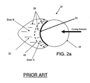
- FIG. 1 a typical acetabular reamer 10 of the prior art is shown.
- the reamer 10 has a cutting bowl or shell 12 defining a surface 14 on which are located teeth 16 adjacent openings 18.
- a base 20 provides a tool-engaging device (not shown).
- a tooth 16 of the reamer 10 is shown.
- the tooth 16 has a diverging surface 22 ("rise”, marked Zone A) backing up the cutting edge 20.
- Zone A a diverging surface 22
- This surface 30 begins to curve inwardly toward the surface of Zone B, and then towards the reamer cutting bowl surface 14.
- Surface reflection lines 28 help indicate the form of these surfaces.
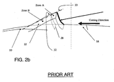
- FIG. 2b a cross sectional side view of the tooth profile 32 of the prior art reamer 10 is shown.
- the form of the profile 32 of the rise 22 is non-linear as indicated.
- Zone A the diverging surfaces 22 of Zone A are visible when one examines a front view of the tooth 16 of the prior art reamer 10.
- corresponding portions of the rise 22 are not visible in a front view but are hidden from view, due to their convergence toward an apex.
- rises 22, respective cutting edges 20, and openings 18 are either positioned on the reamer cutting surface in a spiral arrangement, staggered in another manner, or randomly placed.
- the term "spiral” is meant to include any form in which the cutting teeth 16 are orderly organized in a manner to sweep out the entire shape to be cut
- a preferred spiral arrangement is an arrangement in which adjacent teeth are uniformly angularly offset from each other at any adjacent circle of latitude, namely, that adjacent teeth lie on differing circles of longitude evenly spaced apart from one another. Further, it is preferred that there be a given overlap between adjacent cutting rings (i.e., the rings swept out by each tooth 16).
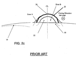
- the profile 70 is shown of a prior art tooth 72 of a reamer known as the "DR reamer", the subject of US Patent No. 5,968,049 .
- the tooth 72 of the DR reamer forms a chord which intersects the profile 70 of the desired cut at two points 74 and 76. Therefore, these prior art reamers have no peak in the typical case.
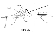
- the present invention has a cutting shell 12' on which are located a series of doubly-curved cutting teeth 16' thereon of a quantity to substantially reduce a cutting pressure on each tooth as well as to reduce a size of a typical chip generated upon cutting.
- Substantially all the teeth 16' each have a matched arc cutting edge 20' of substantial length that has a cutting profile which substantially matches a profile of a shape to be cut.
- the matched arc cutting edge 20' is adjacent secondary cutting edges 21' supported by adjacent rise portions 29', characterizable as gusset or buttress portions, which curve back toward the cutting shell 12' and support the secondary cutting edges 21'.
- the overall cutting edges 20' are therefore doubly-curved in that at least two distinct curves are required to define each cutting edge 20'.
- a smooth-edged opening 18' precedes the cutting edges as the reamer 10' is rotated for cutting.
- openings 18' By defining the openings 18' as being “smooth-edged”, it is meant to define a non-circular opening in which there are no slits or narrow grooves which can cause stress concentrations or soft tissue snag or tear points. Such a configuration reduces the number of teeth required to cut the shape and minimizes the risk of snagging or tearing soft tissue during use. The invention thus gives an improved quality of cut surface and allows fewer teeth 16' to be employed.
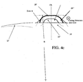
- the cutting edge 20' appears straight in the figure, it actually follows the contour of the surface to be cut, in this case, a hemispherical surface.
- the radius R of the cutting edge 20' matches the radius of the surface to be cut.
- the new tooth 16' is not generated by the manufacture of a larger or wider opening 18 adjacent to the tooth.
- the tooth 16' is generated by the manner in which the tooth is deformed and the profile of the eventual shape.
- the rise 22' approximates the shape of a rectangular prism intersecting the cutting bowl at a tangent to the surface of the cutting bowl 12.
- the teeth 16' have clearly diverging surfaces (in Zone A) which follow the cutting edge 20'. Note that common reference numerals are used for the same or analogous features throughout the drawings.
- FIGs. 4e and 4d alternative examples of the teeth 16' not according to the invention include one in which the tooth is formed from the straight side 80 of the hole 18' ( Fig. 4e ) and one in which the hole is of a triangular shape ( FIG. 4d ).
- the side and front views of such alternate embodiments are substantially identical to that shown in FIGs. 4b and 4c , respectively.
- a different part of the sector is cut by a different tooth 16'.
- the cutting edge protrudes only 0.5 mm above the surface of the hemispherical shell 14, the fact that the openings are larger means that the effective cutting height may be greater than the 0.5mm, due to the fact that the perpendicular distance from the center of the outermost edge of the cutting edge 20' and a cord extending across the aperture 18' is significantly greater than 0.5mm.
- a series of cutting teeth 16' on the cutting shell 12' substantially reduces the cutting pressure on each tooth as well as reduces the size of a typical chip generated upon cutting.
- the ability to use fewer teeth 16' further allows sections 50 (shown in FIG. 5 ) of the hemisphere to be removed while maintaining a high quality of cut surface.
- An example of a acetabular reamer with sections cut away is given in the diagrams of PCT applications serial numbers PCI/IB01/02675 and PCI/IB01/02676 entitled HOLDER FOR A SURGICAL REAMER and SURGICAL REAMER, respectively, filed on 21 Dec. 2001.
- the present invention generates a tooth 16' with a wider cutting profile that is therefore easier to overlap with the cut generated by the next tooth at a different latitudinal elevation on the hemisphere. Additionally the tooth 16' cuts a sector of the required hemisphere, matching the required radius exactly. The improved tooth allows a full hemisphere to be cut with fewer teeth than the typical cheese grater-type reamer..
- the reamer 10' includes a series of cutting teeth 16' arranged uniformly and spaced apart on the cutting shell. These teeth 16' may be arranged in a spiral arrangement on the cutting shell 12'.
- the cutting shell is a portion of a hemisphere, in this case, in which sections 50 (shown by dashed lines) have been removed in the manufacturing process.
- the length of the cutting edges are selected so as to completely cut the shape while being of a number that still ensures good mechanical strength. The longer cutting edges allows the use of less teeth while still cutting a good hemispherical form than permissible with a cutting shell that has a more complete hemispherical shape.
- a tool engaging portion 52 is comprised of two intersecting bars 54 and 56, one bar 54 of which optionally having two flats 60 (only one of which is shown) on its outer ends, adjacent their connecting points on the reamer cutting shell 12'.
- a punch (not shown) of corresponding polygonal form (for which the circumferential location of the edge of the punch used to punch up the cutting edge of the reamer is a known and accurately controlled circumferential distance away from a corresponding flat of the punch) is used to punch up the cutting edge, preferably an amount of 0.5mm, which is half the amount that such teeth are typically punched up.
- FIG. 6 shows the cutting profile 70 as compared to the profile 71 of the hemispherical shell 14.
- the graph of FIG: 7 is a graph of force vs time for a prior art reamer 10 showing how quickly the cutting forces increase with time.
- FIG. 8 the same graph of force vs time for the reamer 10' of the present invention shows that the cutting forces remain relatively constant over as many as 20 uses, about two times less than a cheese-grater-type reamer. Lower cutting forces mean lower heat generation and less dead tissue. Less dead tissue improves the recovery time of the patient.
- the method 100 of fabrication of the invention includes several steps.
- a formed blank is formed from sheet material, cast in an investment or die casting, or formed from powered metal which is sintered prior to further processing.
- the apertures 18' are cut, optionally with a laser, and/or broached, so as to include at least one straight indexing edge.
- a punch (not shown) is inserted into each aperture for the forming of a cutting edge, the indexing edge of the blank abutting against a corresponding surface of the punch, this corresponding surface of the punch being oriented in a known manner, at a known distance from a cutting edge forming surface having contoured-to-match-the-cut-form surface on the punch.
- the punch punches up the cutting edge 20'.
- steps 106 and 110 are repeated until all apertures which are to receive cutting edges are treated, after which, the processed blank is sent downstream for the mounting of cross bars 52 and 54, and further final finishing steps.
- a reamer is provided which substantially reduces a cutting pressure on each tooth as well as reduces the size of a typical chip generated upon cutting.
- the apertures on which the cutting edges are formed are non-circular, thus providing an indexing surface permitting the accurate locating of tools which form the cutting edge.
- the invention results in improved quality of the cut and orientation of the cutting edge, thereby improving the quality of the cut surface and permitting fewer teeth to be used.
Landscapes
- Health & Medical Sciences (AREA)
- Surgery (AREA)
- Life Sciences & Earth Sciences (AREA)
- Medical Informatics (AREA)
- Animal Behavior & Ethology (AREA)
- Orthopedic Medicine & Surgery (AREA)
- Oral & Maxillofacial Surgery (AREA)
- Engineering & Computer Science (AREA)
- Biomedical Technology (AREA)
- Heart & Thoracic Surgery (AREA)
- Dentistry (AREA)
- Molecular Biology (AREA)
- Nuclear Medicine, Radiotherapy & Molecular Imaging (AREA)
- General Health & Medical Sciences (AREA)
- Public Health (AREA)
- Veterinary Medicine (AREA)
- Prostheses (AREA)
- Surgical Instruments (AREA)
- Electrical Discharge Machining, Electrochemical Machining, And Combined Machining (AREA)
- Mounting, Exchange, And Manufacturing Of Dies (AREA)
- Threshing Machine Elements (AREA)
Claims (8)
- Hüftgelenkspfannen-Fräse (10') zum Abtragen einer erforderlichen Abtrag-Form, umfassend- eine Abtrag-Mantelfläche (12'), welche ein Teil einer Kugel ist, wobei die Abtrag-Mantelfläche (12') darauf aufweist- Abtrag-Zähne (16, 16'), wobei im Wesentlichen alle Zähne (16') doppelt gebogen sind und eine Abtrag-Kante (20') mit angepasstem Bogen von beträchtlicher Länge aufweisen, wobei die Abtrag-Kante (20') mit angepasstem Bogen ein Abtrag-Profil aufweist, das im Wesentlichen zu einem Profil mit der abzutragenden Form passt, wodurch eine Verringerung der Zahl von Zähnen (16, 16') ermöglicht wird, die nötig sind, um die Form abzutragen, und worin die Zähne (16') Stütz-Teile (29') haben, die die Abtrag-Kante (20') mit angepasstem Bogen in die Abtrag-Mantelfläche (12') überleiten;- Löcher (18') mit glatter Kante, die jedem Abtrag-Zahn (16, 16') in Orientierung der beabsichtigten Umdrehung der Fräse (10') während des Abtragens voranlaufen, worin die Löcher (18') mit glatter Kante, die keine Spalte oder schmale Rillen aufweisen, eine gerade Kante (80) und eine kreisförmige Kante (19) umfassen;
dadurch gekennzeichnet, dass- die Abtrag-Kante (20') auf der allgemein kreisförmigen Kante (19) ausgebildet ist und die gerade Kante (80) der Abtrag-Kante (20') voranläuft, wenn die Fräse (10') zum Abtragen in Rotation versetzt wird. - Fräse (10') nach Anspruch 1, worin eine Serie von Abtrag-Zähnen (16, 16') gleichmäßig und voneinander beabstandet auf der Abtrag-Mantelfläche (12') angeordnet ist.
- Fräse (10') nach irgendeinem der Ansprüche 1 oder 2, worin die Abtrag-Zähne (16, 16') in einer Spiral-Anordnung auf der Abtrag-Mantelfläche (12') angeordnet sind.
- Fräse (10') nach irgendeinem der Ansprüche 1 bis 3, worin die Längen der Abtrag-Kanten (20') so gewählt sind, dass sie die Form vollständig abtragen, so dass dadurch weniger Zähne (16, 16') benötigt werden als bei einer Abtrag-Mantelfläche (12'), die Zähne mit einer schmalen Krone (38) aufweist.
- Fräse (10') nach irgendeinem der Ansprüche 1 bis 4, worin die Abtrag-Mantelfläche (12') eine Halbkugel oder ein Teil davon ist.
- Verfahren zur Ausbildung der Kontur-Fräse (10') nach Anspruch 1, wobei das Verfahren die folgenden Schritte einschließt:(a) Ausbilden eines Formlings, der die Wölbung eines Teils einer Kugel hat;(b) Abtragen der Löcher (18') mit glatter Kante in dem Formling;(c) Verwenden der geraden Kante (80) zum Orientieren eines Stanzers in Bezug auf die Löcher (18');(d) sobald der Stanzer richtig orientiert ist: Aufstanzen der Abtrag-Kante (20') an dem Formling; und(e) Wiederholen der Schritte (c) und (d), bis alle Löcher (18'), für die eine Abtrag-Kante (20') gewünscht ist, gestanzt sind.
- Verfahren nach Anspruch 6, worin die Abtrag-Zähne (16, 16') gleichmäßig und voneinander beabstandet auf der Abtrag-Mantelfläche (12') angeordnet sind.
- Verfahren nach Anspruch 6 oder Anspruch 7, worin die Abtrag-Zähne (16, 16') in einer Spiral-Anordnung auf der Abtrag-Mantelfläche (12') angeordnet sind.
Applications Claiming Priority (2)
| Application Number | Priority Date | Filing Date | Title |
|---|---|---|---|
| US11/257,417 US7909828B2 (en) | 2003-01-16 | 2005-10-24 | Contoured reamer teeth and method of manufacture |
| PCT/IB2006/002927 WO2007049113A1 (en) | 2005-10-24 | 2006-10-19 | Contoured reamer teeth and method of manufacture |
Publications (2)
| Publication Number | Publication Date |
|---|---|
| EP1951131A1 EP1951131A1 (de) | 2008-08-06 |
| EP1951131B1 true EP1951131B1 (de) | 2011-02-02 |
Family
ID=37758783
Family Applications (1)
| Application Number | Title | Priority Date | Filing Date |
|---|---|---|---|
| EP06809067A Active EP1951131B1 (de) | 2005-10-24 | 2006-10-19 | Konturierte fräsenzähne und herstellungsverfahren |
Country Status (7)
| Country | Link |
|---|---|
| US (2) | US7909828B2 (de) |
| EP (1) | EP1951131B1 (de) |
| JP (1) | JP5308158B2 (de) |
| CN (1) | CN101325917B (de) |
| AT (1) | ATE497363T1 (de) |
| DE (1) | DE602006019976D1 (de) |
| WO (1) | WO2007049113A1 (de) |
Families Citing this family (25)
| Publication number | Priority date | Publication date | Assignee | Title |
|---|---|---|---|---|
| US7918856B2 (en) * | 2002-10-08 | 2011-04-05 | Greatbatch Medical S.A. | Guided reamer system for reshaping bone |
| GB0516625D0 (en) * | 2005-08-15 | 2005-09-21 | Eurocut Ltd | Orthopaedic surgical instrument |
| GB0519084D0 (en) * | 2005-09-19 | 2005-10-26 | Finsbury Dev Ltd | Tool |
| US20080009952A1 (en) * | 2006-06-30 | 2008-01-10 | Hodge W A | Precision acetabular machining system and resurfacing acetabular implant |
| US8403931B2 (en) * | 2007-02-09 | 2013-03-26 | Christopher G. Sidebotham | Modular tapered hollow reamer for medical applications |
| US8535316B2 (en) * | 2007-02-09 | 2013-09-17 | Randall J. Lewis | Hollow reamer for medical applications |
| US8556897B2 (en) | 2007-02-09 | 2013-10-15 | Christopher G. Sidebotham | Modular spherical hollow reamer assembly for medical applications |
| US8449545B2 (en) * | 2007-02-09 | 2013-05-28 | Christopher G. Sidebotham | Low cost modular tapered hollow reamer for medical applications |
| US8523866B2 (en) * | 2007-02-09 | 2013-09-03 | Christopher G. Sidebotham | Modular tapered hollow reamer for medical applications |
| US8518043B2 (en) * | 2007-02-09 | 2013-08-27 | Christopher G. Sidebotham | Modular spherical hollow reamer assembly for medical applications |
| US8357163B2 (en) | 2007-02-09 | 2013-01-22 | Sidebotham Christopher G | Low cost modular tapered and spherical hollow reamers for medical applications |
| US8679124B2 (en) * | 2007-12-20 | 2014-03-25 | Greatbatch Medical S.A. | Disposable acetabular reamer from flat stock |
| US8556901B2 (en) | 2009-12-31 | 2013-10-15 | DePuy Synthes Products, LLC | Reciprocating rasps for use in an orthopaedic surgical procedure |
| US8506569B2 (en) | 2009-12-31 | 2013-08-13 | DePuy Synthes Products, LLC | Reciprocating rasps for use in an orthopaedic surgical procedure |
| US8435243B2 (en) | 2010-02-12 | 2013-05-07 | Greatbatch Ltd. | Disposable reamer |
| US9107677B2 (en) | 2011-01-21 | 2015-08-18 | Greatbach Ltd. | Disposable surgical hemispherical cutter for convex and concave surfaces |
| US8486076B2 (en) | 2011-01-28 | 2013-07-16 | DePuy Synthes Products, LLC | Oscillating rasp for use in an orthopaedic surgical procedure |
| US10863993B2 (en) | 2012-01-13 | 2020-12-15 | Christopher G. Sidebotham | System and method for preparing prosthetic hip implantation |
| CN104244847B (zh) * | 2012-01-13 | 2017-06-09 | 克里斯托弗·G·赛德博特姆 | 医用铰刀及形成医用铰刀的方法 |
| USD732166S1 (en) * | 2013-05-20 | 2015-06-16 | Hpf Spa | Milling tool for prosthetic surgery operations |
| USD732165S1 (en) * | 2013-05-20 | 2015-06-16 | Hpf Spa | Combined milling tool and attachment for a surgery instrument for prosthetic surgery operations |
| CN104688297A (zh) * | 2015-03-26 | 2015-06-10 | 常州玛斯特精密工具有限公司 | 髋臼锉 |
| FR3053883B1 (fr) | 2016-07-12 | 2022-04-29 | Deuxventorio Sarl | Procede de fabrication d'un alesoir |
| CN110799134B (zh) * | 2017-06-30 | 2023-02-28 | 因西坡设备公司 | 单块髋臼扩孔钻 |
| IT202000019411A1 (it) * | 2020-08-06 | 2022-02-06 | Hpf S R L | Linea di lavorazione robotizzata per la realizzazione di corpi taglienti, corpo tagliente e relativo metodo di lavorazione |
Family Cites Families (32)
| Publication number | Priority date | Publication date | Assignee | Title |
|---|---|---|---|---|
| US1768463A (en) * | 1930-06-24 | Canada | ||
| US499619A (en) * | 1893-06-13 | Alfred weed | ||
| FR1031888A (fr) | 1951-01-30 | 1953-06-26 | Outil en forme de fraise, utilisable en particulier pour creuser les cotyles | |
| US3389447A (en) * | 1967-05-26 | 1968-06-25 | Theobald Elwin | Omnidirectional cutting tool |
| DE1566114A1 (de) | 1967-12-22 | 1970-10-22 | Link Waldemar Fa | Verfahren und Fraeser zum Herstellen der Kammer fuer die Aufnahme einer kuenstlichen Hueftkappe in der Hueftpfanne |
| US3604490A (en) * | 1969-11-12 | 1971-09-14 | Melvin E Bricker | Shredder plate |
| FR2233972A1 (en) | 1973-06-22 | 1975-01-17 | C E R A V E R | Artificial hip joint fitting equipment - has drilling jig in round cutter head for retaining boss socket |
| AT345445B (de) * | 1974-08-06 | 1978-09-11 | Weigand Hanfried Dr Med | Fraeswerkzeug zur aufbereitung des pfannenlagers bei totalprothetischem hueftgelenkersatz |
| US4598447A (en) * | 1984-09-20 | 1986-07-08 | File Sharpening Company | Farrier's file/rasp |
| US4811632A (en) * | 1986-02-04 | 1989-03-14 | Othy, Inc. | Method of producing an acetabular reamer cup |
| DE3934610A1 (de) | 1989-10-17 | 1991-04-25 | Aesculap Ag | Schnellkupplung fuer chirurgische instrumente |
| US5116165A (en) * | 1991-03-11 | 1992-05-26 | Othy, Inc. | Acetabular reamer cup |
| US5299893A (en) * | 1991-03-13 | 1994-04-05 | Othy, Inc. | Disposable surgical cutters |
| US5171313A (en) * | 1991-05-08 | 1992-12-15 | Othy, Inc. | Tool driver |
| US5222956A (en) * | 1992-07-06 | 1993-06-29 | Altair Instruments, Inc. | Surgical drill collet mechanism and bur |
| US5709688A (en) * | 1995-06-07 | 1998-01-20 | Othy, Inc. | Acetabular reamer cup and method of producing the same |
| US5755719A (en) * | 1997-01-15 | 1998-05-26 | Case Medical, Inc. | Acetabular reamer |
| CH692178A5 (de) * | 1997-05-22 | 2002-03-15 | Precimed Sa | Fräser für medizinische Zwecke. |
| DE19731522C1 (de) | 1997-07-23 | 1999-02-11 | Eska Implants Gmbh & Co | Halter für ein chirurgisches Instrument |
| CH692600A5 (fr) | 1998-04-02 | 2002-08-30 | Precimed Sa | Fraise chirurgicale. |
| US6168600B1 (en) * | 1999-08-20 | 2001-01-02 | Grace Manufacturing, Inc. | Acetabular reamer backing plate and method of use |
| USD447021S1 (en) * | 1999-11-11 | 2001-08-28 | Salvatore V. Mistretta | Grater for food products |
| US6283971B1 (en) * | 2000-04-25 | 2001-09-04 | Randy S. Temeles | Expandable acetabular reaming system |
| JP2004516061A (ja) | 2000-12-21 | 2004-06-03 | プレシメッド エス.アー. | 手術用リーマ |
| USD468398S1 (en) * | 2001-04-27 | 2003-01-07 | Blanco Gmbh + Co Kg | Mixing tap |
| US6730094B2 (en) * | 2002-01-14 | 2004-05-04 | Symmetry Medical Usa, Inc. | Cutting edges for reamers and a method for making same |
| CN100518671C (zh) * | 2002-01-16 | 2009-07-29 | 普雷西梅德公司 | 成型扩孔钻齿 |
| US20030220647A1 (en) * | 2002-05-21 | 2003-11-27 | Mccallum Kevin | Low profile acetabular reamer |
| US7220264B1 (en) * | 2003-03-12 | 2007-05-22 | Biomet Manufacturing Corp. | Minimally invasive reamer |
| US20050059974A1 (en) * | 2003-09-15 | 2005-03-17 | Wolford Todd A. | Method of manufacturing an orthopaedic reamer |
| US7217272B2 (en) * | 2003-11-25 | 2007-05-15 | Symmetry Medical, Inc. | Orthopaedic rotary reamer with implant compliant cutting teeth |
| US7896881B2 (en) * | 2004-03-30 | 2011-03-01 | Depuy Products, Inc. | Acetabular instrument and associated method |
-
2005
- 2005-10-24 US US11/257,417 patent/US7909828B2/en active Active
-
2006
- 2006-10-19 US US12/091,298 patent/US7922722B2/en not_active Expired - Lifetime
- 2006-10-19 CN CN2006800466965A patent/CN101325917B/zh active Active
- 2006-10-19 AT AT06809067T patent/ATE497363T1/de not_active IP Right Cessation
- 2006-10-19 JP JP2008537212A patent/JP5308158B2/ja active Active
- 2006-10-19 WO PCT/IB2006/002927 patent/WO2007049113A1/en active Application Filing
- 2006-10-19 EP EP06809067A patent/EP1951131B1/de active Active
- 2006-10-19 DE DE602006019976T patent/DE602006019976D1/de active Active
Also Published As
| Publication number | Publication date |
|---|---|
| US20080243124A1 (en) | 2008-10-02 |
| ATE497363T1 (de) | 2011-02-15 |
| CN101325917B (zh) | 2011-07-06 |
| JP2009512530A (ja) | 2009-03-26 |
| US7922722B2 (en) | 2011-04-12 |
| US7909828B2 (en) | 2011-03-22 |
| CN101325917A (zh) | 2008-12-17 |
| US20060095041A1 (en) | 2006-05-04 |
| WO2007049113A1 (en) | 2007-05-03 |
| EP1951131A1 (de) | 2008-08-06 |
| DE602006019976D1 (de) | 2011-03-17 |
| JP5308158B2 (ja) | 2013-10-09 |
Similar Documents
| Publication | Publication Date | Title |
|---|---|---|
| EP1951131B1 (de) | Konturierte fräsenzähne und herstellungsverfahren | |
| US7901406B1 (en) | Contoured reamer teeth | |
| US9351740B2 (en) | Acetabular reamer | |
| US6001105A (en) | Acetabular reamer cup and method of producing the same | |
| EP2478852B1 (de) | Chirurgischer halbkugelförmiger Einweg-Schneider für konvexe oder konkave Oberflächen | |
| US5976144A (en) | Hollow dome reamer with removable teeth | |
| US6730094B2 (en) | Cutting edges for reamers and a method for making same | |
| US7837686B1 (en) | Surgical cutting tool | |
| US20040143271A1 (en) | Chip breakers for orthopaedic reamers | |
| US20070118137A1 (en) | Method of manufacturing an orthopaedic reamer | |
| EP1624813B1 (de) | Orthopädisches schneideinstrument |
Legal Events
| Date | Code | Title | Description |
|---|---|---|---|
| PUAI | Public reference made under article 153(3) epc to a published international application that has entered the european phase |
Free format text: ORIGINAL CODE: 0009012 |
|
| 17P | Request for examination filed |
Effective date: 20080523 |
|
| AK | Designated contracting states |
Kind code of ref document: A1 Designated state(s): AT BE BG CH CY CZ DE DK EE ES FI FR GB GR HU IE IS IT LI LT LU LV MC NL PL PT RO SE SI SK TR |
|
| RAP1 | Party data changed (applicant data changed or rights of an application transferred) |
Owner name: GREATBATCH MEDICAL SA |
|
| 17Q | First examination report despatched |
Effective date: 20090807 |
|
| GRAP | Despatch of communication of intention to grant a patent |
Free format text: ORIGINAL CODE: EPIDOSNIGR1 |
|
| DAX | Request for extension of the european patent (deleted) | ||
| GRAS | Grant fee paid |
Free format text: ORIGINAL CODE: EPIDOSNIGR3 |
|
| GRAA | (expected) grant |
Free format text: ORIGINAL CODE: 0009210 |
|
| AK | Designated contracting states |
Kind code of ref document: B1 Designated state(s): AT BE BG CH CY CZ DE DK EE ES FI FR GB GR HU IE IS IT LI LT LU LV MC NL PL PT RO SE SI SK TR |
|
| REG | Reference to a national code |
Ref country code: GB Ref legal event code: FG4D |
|
| REG | Reference to a national code |
Ref country code: CH Ref legal event code: EP |
|
| REG | Reference to a national code |
Ref country code: IE Ref legal event code: FG4D |
|
| REF | Corresponds to: |
Ref document number: 602006019976 Country of ref document: DE Date of ref document: 20110317 Kind code of ref document: P |
|
| REG | Reference to a national code |
Ref country code: DE Ref legal event code: R096 Ref document number: 602006019976 Country of ref document: DE Effective date: 20110317 |
|
| REG | Reference to a national code |
Ref country code: NL Ref legal event code: VDEP Effective date: 20110202 |
|
| LTIE | Lt: invalidation of european patent or patent extension |
Effective date: 20110202 |
|
| PG25 | Lapsed in a contracting state [announced via postgrant information from national office to epo] |
Ref country code: LT Free format text: LAPSE BECAUSE OF FAILURE TO SUBMIT A TRANSLATION OF THE DESCRIPTION OR TO PAY THE FEE WITHIN THE PRESCRIBED TIME-LIMIT Effective date: 20110202 Ref country code: PT Free format text: LAPSE BECAUSE OF FAILURE TO SUBMIT A TRANSLATION OF THE DESCRIPTION OR TO PAY THE FEE WITHIN THE PRESCRIBED TIME-LIMIT Effective date: 20110602 Ref country code: GR Free format text: LAPSE BECAUSE OF FAILURE TO SUBMIT A TRANSLATION OF THE DESCRIPTION OR TO PAY THE FEE WITHIN THE PRESCRIBED TIME-LIMIT Effective date: 20110503 Ref country code: IS Free format text: LAPSE BECAUSE OF FAILURE TO SUBMIT A TRANSLATION OF THE DESCRIPTION OR TO PAY THE FEE WITHIN THE PRESCRIBED TIME-LIMIT Effective date: 20110602 Ref country code: SE Free format text: LAPSE BECAUSE OF FAILURE TO SUBMIT A TRANSLATION OF THE DESCRIPTION OR TO PAY THE FEE WITHIN THE PRESCRIBED TIME-LIMIT Effective date: 20110202 Ref country code: ES Free format text: LAPSE BECAUSE OF FAILURE TO SUBMIT A TRANSLATION OF THE DESCRIPTION OR TO PAY THE FEE WITHIN THE PRESCRIBED TIME-LIMIT Effective date: 20110513 Ref country code: LV Free format text: LAPSE BECAUSE OF FAILURE TO SUBMIT A TRANSLATION OF THE DESCRIPTION OR TO PAY THE FEE WITHIN THE PRESCRIBED TIME-LIMIT Effective date: 20110202 |
|
| PG25 | Lapsed in a contracting state [announced via postgrant information from national office to epo] |
Ref country code: FI Free format text: LAPSE BECAUSE OF FAILURE TO SUBMIT A TRANSLATION OF THE DESCRIPTION OR TO PAY THE FEE WITHIN THE PRESCRIBED TIME-LIMIT Effective date: 20110202 Ref country code: PL Free format text: LAPSE BECAUSE OF FAILURE TO SUBMIT A TRANSLATION OF THE DESCRIPTION OR TO PAY THE FEE WITHIN THE PRESCRIBED TIME-LIMIT Effective date: 20110202 Ref country code: AT Free format text: LAPSE BECAUSE OF FAILURE TO SUBMIT A TRANSLATION OF THE DESCRIPTION OR TO PAY THE FEE WITHIN THE PRESCRIBED TIME-LIMIT Effective date: 20110202 Ref country code: BE Free format text: LAPSE BECAUSE OF FAILURE TO SUBMIT A TRANSLATION OF THE DESCRIPTION OR TO PAY THE FEE WITHIN THE PRESCRIBED TIME-LIMIT Effective date: 20110202 Ref country code: SI Free format text: LAPSE BECAUSE OF FAILURE TO SUBMIT A TRANSLATION OF THE DESCRIPTION OR TO PAY THE FEE WITHIN THE PRESCRIBED TIME-LIMIT Effective date: 20110202 Ref country code: NL Free format text: LAPSE BECAUSE OF FAILURE TO SUBMIT A TRANSLATION OF THE DESCRIPTION OR TO PAY THE FEE WITHIN THE PRESCRIBED TIME-LIMIT Effective date: 20110202 Ref country code: BG Free format text: LAPSE BECAUSE OF FAILURE TO SUBMIT A TRANSLATION OF THE DESCRIPTION OR TO PAY THE FEE WITHIN THE PRESCRIBED TIME-LIMIT Effective date: 20110502 Ref country code: CY Free format text: LAPSE BECAUSE OF FAILURE TO SUBMIT A TRANSLATION OF THE DESCRIPTION OR TO PAY THE FEE WITHIN THE PRESCRIBED TIME-LIMIT Effective date: 20110202 |
|
| PG25 | Lapsed in a contracting state [announced via postgrant information from national office to epo] |
Ref country code: DK Free format text: LAPSE BECAUSE OF FAILURE TO SUBMIT A TRANSLATION OF THE DESCRIPTION OR TO PAY THE FEE WITHIN THE PRESCRIBED TIME-LIMIT Effective date: 20110202 Ref country code: EE Free format text: LAPSE BECAUSE OF FAILURE TO SUBMIT A TRANSLATION OF THE DESCRIPTION OR TO PAY THE FEE WITHIN THE PRESCRIBED TIME-LIMIT Effective date: 20110202 |
|
| PG25 | Lapsed in a contracting state [announced via postgrant information from national office to epo] |
Ref country code: RO Free format text: LAPSE BECAUSE OF FAILURE TO SUBMIT A TRANSLATION OF THE DESCRIPTION OR TO PAY THE FEE WITHIN THE PRESCRIBED TIME-LIMIT Effective date: 20110202 Ref country code: SK Free format text: LAPSE BECAUSE OF FAILURE TO SUBMIT A TRANSLATION OF THE DESCRIPTION OR TO PAY THE FEE WITHIN THE PRESCRIBED TIME-LIMIT Effective date: 20110202 Ref country code: CZ Free format text: LAPSE BECAUSE OF FAILURE TO SUBMIT A TRANSLATION OF THE DESCRIPTION OR TO PAY THE FEE WITHIN THE PRESCRIBED TIME-LIMIT Effective date: 20110202 |
|
| PLBE | No opposition filed within time limit |
Free format text: ORIGINAL CODE: 0009261 |
|
| STAA | Information on the status of an ep patent application or granted ep patent |
Free format text: STATUS: NO OPPOSITION FILED WITHIN TIME LIMIT |
|
| 26N | No opposition filed |
Effective date: 20111103 |
|
| REG | Reference to a national code |
Ref country code: DE Ref legal event code: R097 Ref document number: 602006019976 Country of ref document: DE Effective date: 20111103 |
|
| PG25 | Lapsed in a contracting state [announced via postgrant information from national office to epo] |
Ref country code: IT Free format text: LAPSE BECAUSE OF FAILURE TO SUBMIT A TRANSLATION OF THE DESCRIPTION OR TO PAY THE FEE WITHIN THE PRESCRIBED TIME-LIMIT Effective date: 20110202 Ref country code: MC Free format text: LAPSE BECAUSE OF NON-PAYMENT OF DUE FEES Effective date: 20111031 |
|
| REG | Reference to a national code |
Ref country code: CH Ref legal event code: PL |
|
| GBPC | Gb: european patent ceased through non-payment of renewal fee |
Effective date: 20111019 |
|
| PG25 | Lapsed in a contracting state [announced via postgrant information from national office to epo] |
Ref country code: CH Free format text: LAPSE BECAUSE OF NON-PAYMENT OF DUE FEES Effective date: 20111031 Ref country code: LI Free format text: LAPSE BECAUSE OF NON-PAYMENT OF DUE FEES Effective date: 20111031 |
|
| REG | Reference to a national code |
Ref country code: IE Ref legal event code: MM4A |
|
| PG25 | Lapsed in a contracting state [announced via postgrant information from national office to epo] |
Ref country code: GB Free format text: LAPSE BECAUSE OF NON-PAYMENT OF DUE FEES Effective date: 20111019 |
|
| PG25 | Lapsed in a contracting state [announced via postgrant information from national office to epo] |
Ref country code: IE Free format text: LAPSE BECAUSE OF NON-PAYMENT OF DUE FEES Effective date: 20111019 |
|
| PG25 | Lapsed in a contracting state [announced via postgrant information from national office to epo] |
Ref country code: LU Free format text: LAPSE BECAUSE OF NON-PAYMENT OF DUE FEES Effective date: 20111019 |
|
| PG25 | Lapsed in a contracting state [announced via postgrant information from national office to epo] |
Ref country code: TR Free format text: LAPSE BECAUSE OF FAILURE TO SUBMIT A TRANSLATION OF THE DESCRIPTION OR TO PAY THE FEE WITHIN THE PRESCRIBED TIME-LIMIT Effective date: 20110202 |
|
| PG25 | Lapsed in a contracting state [announced via postgrant information from national office to epo] |
Ref country code: HU Free format text: LAPSE BECAUSE OF FAILURE TO SUBMIT A TRANSLATION OF THE DESCRIPTION OR TO PAY THE FEE WITHIN THE PRESCRIBED TIME-LIMIT Effective date: 20110202 |
|
| REG | Reference to a national code |
Ref country code: DE Ref legal event code: R082 Ref document number: 602006019976 Country of ref document: DE Representative=s name: SCHWABE SANDMAIR MARX PATENTANWAELTE RECHTSANW, DE Ref country code: DE Ref legal event code: R082 Ref document number: 602006019976 Country of ref document: DE Representative=s name: SSM SANDMAIR PATENTANWAELTE RECHTSANWALT PARTN, DE |
|
| REG | Reference to a national code |
Ref country code: FR Ref legal event code: PLFP Year of fee payment: 11 |
|
| REG | Reference to a national code |
Ref country code: FR Ref legal event code: PLFP Year of fee payment: 12 |
|
| REG | Reference to a national code |
Ref country code: FR Ref legal event code: PLFP Year of fee payment: 13 |
|
| PGFP | Annual fee paid to national office [announced via postgrant information from national office to epo] |
Ref country code: FR Payment date: 20230821 Year of fee payment: 18 |
|
| PGFP | Annual fee paid to national office [announced via postgrant information from national office to epo] |
Ref country code: DE Payment date: 20230822 Year of fee payment: 18 |