EP1950530A2 - Road map data structure, road map data storage medium and navigation device - Google Patents
Road map data structure, road map data storage medium and navigation device Download PDFInfo
- Publication number
- EP1950530A2 EP1950530A2 EP07150022A EP07150022A EP1950530A2 EP 1950530 A2 EP1950530 A2 EP 1950530A2 EP 07150022 A EP07150022 A EP 07150022A EP 07150022 A EP07150022 A EP 07150022A EP 1950530 A2 EP1950530 A2 EP 1950530A2
- Authority
- EP
- European Patent Office
- Prior art keywords
- link
- road
- attribute
- map data
- data
- Prior art date
- Legal status (The legal status is an assumption and is not a legal conclusion. Google has not performed a legal analysis and makes no representation as to the accuracy of the status listed.)
- Granted
Links
- 238000013500 data storage Methods 0.000 title claims description 10
- 238000000034 method Methods 0.000 claims description 18
- 238000001514 detection method Methods 0.000 claims description 8
- 238000004364 calculation method Methods 0.000 description 34
- 230000000875 corresponding effect Effects 0.000 description 16
- 230000006870 function Effects 0.000 description 7
- 230000005540 biological transmission Effects 0.000 description 5
- 238000010586 diagram Methods 0.000 description 4
- 239000008358 core component Substances 0.000 description 1
- 230000002596 correlated effect Effects 0.000 description 1
- 230000001419 dependent effect Effects 0.000 description 1
- 239000004973 liquid crystal related substance Substances 0.000 description 1
Images




Classifications
-
- G—PHYSICS
- G01—MEASURING; TESTING
- G01C—MEASURING DISTANCES, LEVELS OR BEARINGS; SURVEYING; NAVIGATION; GYROSCOPIC INSTRUMENTS; PHOTOGRAMMETRY OR VIDEOGRAMMETRY
- G01C21/00—Navigation; Navigational instruments not provided for in groups G01C1/00 - G01C19/00
- G01C21/38—Electronic maps specially adapted for navigation; Updating thereof
- G01C21/3804—Creation or updating of map data
- G01C21/3807—Creation or updating of map data characterised by the type of data
- G01C21/3815—Road data
-
- G—PHYSICS
- G01—MEASURING; TESTING
- G01C—MEASURING DISTANCES, LEVELS OR BEARINGS; SURVEYING; NAVIGATION; GYROSCOPIC INSTRUMENTS; PHOTOGRAMMETRY OR VIDEOGRAMMETRY
- G01C21/00—Navigation; Navigational instruments not provided for in groups G01C1/00 - G01C19/00
- G01C21/38—Electronic maps specially adapted for navigation; Updating thereof
- G01C21/3863—Structures of map data
- G01C21/387—Organisation of map data, e.g. version management or database structures
- G01C21/3878—Hierarchical structures, e.g. layering
Definitions
- the present invention relates to a structure of road map data used in a navigation device, for example, and more particularly, to a road map data structure which contains the road network data representing roads in connection with plural links, a road map data storage medium which stores the road network data, and a navigation device using the road map data storage medium.
- road map data contain road network data at plural levels corresponding to the level of detail or the scale for the display of the road information to be stored.
- the respective road network data at the corresponding level represent the road in connection with the plural links.
- link IDs are sequentially provided in the order of the connection in a link string by the respective link strings including plural successive links each having the common attribute.
- the link ID structured to have a predetermined numerical range which contains plural successive numbers is known. There has been also known that the range proportional to each link length of the respective links is set to the numerical range of the link ID as disclosed in Japanese Patent No. 3725022 and Japanese Patent Application Publication No. JP-A-2005-70482 .
- the link ID has a predetermined numerical range.
- the numerical range of the link ID of the existing link is divided to newly generate plural link IDs so as to be assigned to the respective divided sections of the existing link. This makes it possible to easily update for adding the new link while maintaining the continuity of the link ID.
- a road map data structure is provided with road network data which represent a road in connection with plural links, and a link ID is assigned to each of the links of the road network data, and the link ID has a numerical range set in accordance with both a link length of the link and a road attribute, and further is sequentially set in a connection order within a link string for the each link string composed of the plural links connecting in line.
- the numerical range of the link ID of the link with a road attribute with high possibility to be divided accompanied with the addition of the new link upon prospective updating of the road network data with respect to the link length is set to be wide depending on the road attribute of the link. This ensures sufficient number of times for dividing the subject link while maintaining the continuity of the link ID. Meanwhile, the numerical range of the link ID with respect to the link length with the road attribute having the low possibility to be divided is set to be small. This makes it possible to suppress the total numerical range of the link ID required for identifying all the links which form the road network as small as possible, thus reducing the digit number of each numerical range of the respective link IDs.
- This also makes it possible to realize the road map data structure capable of performing sufficient number of times for dividing the link depending on the road attribute of the link while maintaining the continuity of the link ID for the prospective updating, and capable of suppressing the data size for representing each link ID of the respective links as small as possible.
- the road attribute includes at least one of a category attribute with respect to a road category of the link, and an area attribute with respect to an area where the link exists.
- the numerical range of the link ID may be appropriately set depending on at least one of the road category of the respective links and the area where the respective links exist, which may greatly influence the possibility of dividing the link accompanied with the updating of the road network data.
- the numerical range of the link ID is set based on a value obtained by multiplying the link length of the link by an attribute coefficient determined in accordance with the road attribute of the link.
- the aforementioned structure allows the numerical range of the link ID to be appropriately set depending on the link length and the road attribute of the respective links.
- the attribute coefficient is preliminarily set for each of plural attribute sections divided in accordance with the road attribute, and the setting of the attribute coefficient is based on a possibility of link division a cause of update of the road network data on the each of the attribute sections.
- the numerical range of the link ID with respect to the link length may be set to be wide. This ensures sufficient number of times for dividing the link while maintaining the continuity of the link ID, and allows the total numerical range of the link ID required for identifying all the links which form the road network data to be reduced as small as possible. This makes it possible to realize the road map data structure capable of reducing the size of data for representing the link IDs of the respective links as small as possible.
- the attribute section includes at least three category attribute sections of a main road of highway, a side road of highway and a general road; and the attribute coefficient of the category attribute section is made larger in the order of the main road of highway, the side road of highway and the general road.
- the possibility of dividing the link corresponding to the main road of highway accompanied with updating of the road network data is low as the new road is not connected to the main road of highway unless the interchange, service area, parking area and the like are newly built.
- the possibility that the new road is connected to the general road is relatively high.
- the possibility that new road is connected to the interchange, service area, parking area, and the side road to the highway, for example, the guide path connected to the main road of the highway is higher than the possibility in case of the main road of highway, and is lower than the possibility in case of the general road. Accordingly, the structure allows the numerical range of the link ID to be appropriately set depending on the possibility of dividing the link based on the road category thereof.
- the attribute section includes at least two area attribute sections of an urban area and a local area; and the attribute coefficient of the area attribute section is made larger in the order of the local area and the urban area.
- the frequency of updating the road in the urban area is higher than that of updating the road in the local area.
- the possibility of dividing the link accompanied with updating of the road network data resulting from connection of the new road is relatively high. Accordingly, the structure allows the numerical range of the link ID to be appropriately set depending on the possibility of dividing the link based on the area where the link exists.
- the road map data having the road map data structure with aforementioned structure is stored in the storage medium and preferably used as the road map data storage medium.
- a navigation device includes a map database which stores road map data having the aforementioned structure, a self location detection unit for detecting a self location, an application program operated in reference to the road map data; and a guide information output unit operated in accordance with the application program for outputting guide information.
- the aforementioned structure allows the map database of the navigation device to be provided with the road map data capable of ensuring sufficient number of times for dividing each link depending on the road attribute of the link while maintaining the continuity of the link ID for the prospective updating of the road network data, and capable of suppressing the size of data for representing the link ID of the link as small as possible. Accordingly, the road network data may be appropriately updated, and the continuity of the link ID may be maintained even after the updating.
- the resultant navigation device prevents the speed of the processing relative to reading of the road map data from being lowered.
- FIG. 1 is a block diagram schematically showing the structure of a navigation device 1 according to the embodiment.
- the navigation device 1 is structured to perform general navigation functions for displaying the self location, searching the route from the current position to the destination, guiding the route to the destination, retrieving the destination and the like.
- the navigation device 1 is formed of a map database 2, a calculation section 3, a self location detection section 4, a memory 5, a communication section 6, a display input section 7, and a voice output section 8.
- the respective function sections of the navigation device 1 are formed by mounting the hardware and/or the software (program) for executing various types of the process with respect to the input data, having the calculation section 3 formed of the CPU (Central Processing Unit) as the core component.
- the CPU Central Processing Unit
- the map database 2 stores road map data RD to which the calculation section 3 refers in accordance with the application program PG1 to be described later.
- the map database 2 has a hardware structure including a writable storage medium such as a hard disk drive and the flash memory, and a drive unit for driving the storage medium.
- the map database 2 corresponds to the "road map data storage medium" which stores the road map data RD according to the present invention.
- the road map data RD stored in the map database 2 has the data structure according to the present invention.
- the map database 2 stores various data (guiding data) for displaying, guiding, searching so as to be used in the application program PG1, which are not shown in the drawing.
- the aforementioned data include image data, voice data, POI (Point of Interest) and the like, each data of which are stored in correlation with the link and node (see FIG. 3 ) contained in the road map data RD.
- the structure of the road map data RD will be described in detail referring to FIGS. 2 and 3 .
- FIG. 2 is an explanatory view showing the layer structure with respect to plural sections p which form the road map data RD.
- the road map data RD includes plural levels, and the map data at the respective levels are divided into plural sections p corresponding to the level. As the level becomes high, the section p corresponds to the wider area. The section p at the high level contains the area corresponding to the plural sections p at the lower level.
- the road map data RD includes four levels from the lowest level 0 to the highest level 3.
- the map data at the lowest level 0 form the map of the urban area, which is used for showing the road in the urban area in detail to cover the specific area.
- the map data at the level 1 as the lowest level cover the entire area.
- the map data at the level from 1 to 3 include road network data Rn used for the route search and the like, respectively.
- FIG. 3 shows the correlation of the road network data Rn among the respective levels 1 to 3 of the road map data RD.
- the map data at the plural levels in accordance with the detail level and the display scale of the road information to be stored are provided with road network data Rn (Rn1 to Rn3) in the layer structure.
- the road network data Rn at the respective levels graphically represent the actual road in connection with the plural links L.
- the road network data Rn have three levels from the lowest level 1 to the highest level 3.
- the single section p at the high level contains the area corresponding to the plural sections p at the lower level.
- the road network data Rn at the respective levels are structured such that plural links L are connected with one another via nodes N at the respective ends of the links L.
- Each of the nodes N is set corresponding to the intersection on the actual road.
- Each of the links L is set corresponding to the road between the respective intersections.
- the dummy node is set on the boundary of the subject section p irrespective of the intersection on the actual road.
- the node N includes two types, that is, the actual node set corresponding to the intersection on the real road, and the dummy node virtually set on the boundary of the section irrespective of the actual intersection. In the embodiment, both nodes will be generically referred to as the node N.
- the road network data Rn at the respective levels will be generically referred to as the "Rn".
- the road network data may be coded as "Rn1" to "Rn3" corresponding to the levels 1 to 3 for the purpose of distinguishing the level.
- the road network data Rn1 at the lowest level 1 contains the information with respect to the roads which covers the entire road category of the road map data, for example, the highway (including the main road and side road), national road, principal prefectural road, prefectural road, other main numbered road, narrow street and the like.
- the road network data Rn2 and Rn3 at the levels 2 and 3 contain no information with respect to the road with the category regarded as insignificant for searching the route (for example, narrow street).
- the information data representing the nodes N and links L of the road network data Rn are arranged by the respective link strings ML (multi link) (see FIG. 4 ) each having the common road attribute and formed of plural links connected in a line in the order of connection in the link string ML at the respective levels (1 to 3).
- the name of the actual road for example, "national road 1", "Meishin Expressway” is used as the common road attribute which specifies the respective link string ML.
- the link L corresponding to the road with the same name is maintained to form the long link string ML within the section p.
- the common road attribute which specifies the respective link string ML is not limited to the road name, but various road attributes with respect to the road or the link, for example, the road category, number of lanes, road width and the like may be employed.
- the road network data Rn contains attribute information data with respect to the link L and the node N by each link string ML.
- the attribute information of the node N contains the coordinate information showing the coordinate of the node N, the information showing whether the dummy node or the actual node, the information showing the traffic regulation, the information showing the upper limit level where the respective nodes N exist (levels 1 to 3), the information showing presence or absence of the traffic light and the like.
- the attribute information of the link L contains the link ID information showing the link ID of the respective link (described later), the configuration information showing the configuration of the link L, the information showing the traffic regulation, the information showing the road category, the road name information, the information showing the road width, the information of the number of lanes, the information of the upper limit level (levels 1 to 3) where the links L exist and the like.
- the link ID is assigned to each of the links L in the road map data RD as an exclusive ID (identifier) for identifying the respective links so as not to be overlapped.
- the road map data RD are structured to have the numerical range for the respective links L of the road network data Rn, which may be set in accordance with the link length of the link L and the road attribute, and to have the link ID which is set to be sequential in the order of connection in the link string ML by the respective link strings ML each having the plural links L connected in the single line. The structure of the aforementioned link ID will be described in detail.
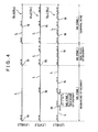
- FIG. 4 shows an exemplary setting of the link IDs of the respective links L which form the road network data Rn1 to Rn3 at the respective levels.
- a predetermined numerical range including plural successive numbers is assigned to the link ID of the link L.
- the link ID with the numerical range is represented by combining the first number and the difference between the first and the last numbers of the link ID.
- the numerical range of the link ID is expressed as "100-13"
- the number "100" is the first number
- the "13” is the difference between the first and the last numbers.
- the sequential numerals ranging from 100 to 113 (natural numbers herein) with the numerical range of "14" is assigned as the link ID.
- the rule for setting the numerical range of the link ID will be described in detail later.
- the link string ML formed of plural links L connected in line includes a first link string ML1, a second link string ML2, a third link string ML3, and a fourth link string ML4.
- the respective link strings are genetically referred to as the code "ML”.
- the codes of "ML1" to "ML4" will be used for distinguishing the respective link strings ML.
- Each of the link IDs of the respective links L is set to be sequential with respect to the strings ML1 to ML4 in the order of connection therein.
- the link IDs of the respective links L in the first link string ML1 of the road network data Rn1 at the level 1 includes "100 - 13", “114-12”, “127-9”, and "137-16" sequentially from the head of the link L (the leftmost link L shown in FIG. 4 ).
- the aforementioned link IDs may be expressed as the numerals as "100-113", “114-126”, “127-136", and "137-153", respectively.
- the link IDs are set such that the numbers are sequentially arranged in the order of connection in the link string ML1.
- the plural links L at the lower level are combined into the single link L.
- the link ID of the thus combined link L is set as the one obtained by combining the link IDs of the respective links L before the combination.
- the link ID of the link L at the level 2 is formed by combining two links L each having the link ID from"100-13" and "114-12" at the level 1 to "100-26" at the level 2.
- the link ID of the link L at the level 2 is formed by integrating two links L each having the link ID of "127-9" and "137-16" at the level 1 to "127 to 26" at the level 2.
- the numerical range of the link ID is set based on the value obtained by multiplying each link length of the links by the attribute coefficient determined by the road attribute of the link.
- the category attribute with respect to the road category, and the area attribute with respect to the area where the respective links exist are used as the road attribute for setting the numerical range of the like ID.
- the category attribute coefficient Ca determined in accordance with the category attribute and the area attribute coefficient Cb determined in accordance with the area attribute are used as the attribute coefficients.
- the numerical range R of the link ID is obtained by calculation of the following equation (1).
- S denotes the reference number representing the reference numerical range per a unit link length.
- the reference number S is set in reference to the numerical range suitable for the link L under the condition where the category attribute is the "general road", and the area attribute is "urban area” to be described later.
- the reference number may be set to "20" per link length of 100 m.
- the "LL” denotes the link length indicating the information of the one corresponding to the actual length of the link L.
- the link length information is contained in the road network data Rn as the attribute information of the respective links L.
- the link ID of the link L is determined by the numerical range R obtained by the aforementioned equation (1) and the first number. In the case where the first number is "100", and the numerical range R is "14", the link ID becomes "100-13".
- the first number of the link ID is the number (natural number) subsequent to the last number of the link ID of the link L as the previous one to which the subj ect link L is connected in the link string ML where the link L exists. In other words, the first number of the link ID of the link L subsequent to the one having the link ID of "100-13" becomes "114".
- the first number of the link ID is set such that the link IDs of all the links L which form the link string ML are not overlapped with those in the other link string ML.
- the numerical range of the link ID is set with respect to the road network data Rn1 at the level 1 as being the lowest based on the aforementioned rule.
- the link ID formed by integrating the link IDs of the link L at the level 1 may be assigned to the road network data Rn2 and Rn3 at the higher levels 2 and 3, respectively.
- the category attribute coefficient Ca and the area attribute coefficient Cb as the attribute coefficients are preliminarily set for plural attribute sections divided in accordance with the respective road attributes (category attribute or area attribute).
- the category attribute coefficient Ca and the area attribute coefficient Cb are set to values determined in accordance with the possibility that the link L is divided by updating of the road network data Rn with respect to the respective attribute sections.
- FIG. 5 is a view showing exemplary attribute sections and corresponding category attribute coefficients Ca.
- FIG. 6 is a view showing exemplary attribute sections and corresponding area attribute coefficients Cb.
- the road category is divided into three sections, that is, "main road of highway", “side road of highway”, and “general road” as category attribute section with respect to the category attribute.
- the category attribute coefficients Ca of the respective category attribute sections are set to the values which become larger in the order of the "main road of highway", “side road of highway”, and “general road”, that is, “0.3”, “0.6", and “1", respectively.
- the section of the "main road of highway” includes the link L which forms the main road of the highway and toll road.
- the section of the "side road of highway” includes the link L which forms the interchange, the service area, and the parking area, and the guide path for connecting the main road of highway to the aforementioned facilities.
- the section of the "general road” includes all the links L which do not belong to the sections of the "main road of highway” and the "side road of highway". More specifically, the link L for forming the national road, principal prefectural road, prefectural road, other main numbered road, and the narrow street are contained.
- the new road is not connected to the road of the category belonging to the section of the "main road of highway” unless the interchange, service area, parking area and the like are newly built. Accordingly, the possibility that the link L belonging to the aforementioned section is divided by updating of the road network data Rn is low. The possibility that the road is newly connected to the road of the category belonging to the "general road” is relatively high.
- the possibility that the road is newly connected to the road of the category belonging to the "side road of highway” is at the medium level between the levels of the "main road of highway” and the "general road”.
- the category attribute coefficient Ca is set to the larger value as the possibility becomes high.
- the area is divided into two sections, that is, "urban area” and "local area” as the area attribute section with respect to the area attribute.
- the area attribute coefficients Cb for the area attribute section are set to the larger values in the order of the "local area” and "urban area”, that is, "0.7” and "1", respectively.
- the determination whether the link L belongs to the "urban area” section or the "local area” section may be made based on presence/absence of at least a part of the link L is contained in the area on the map which has the map data for forming the urban area map at the level 0. The determination may be easily made based on the urban area map which covers only the part of the urban area rather than the entire area of the road map data RD.
- the frequency of updating the road belonging to the "urban area” section is higher than that of updating the road belonging to the "local area” section.
- the possibility that the link is divided by updating of the road network data resulting from newly connected road becomes relatively high.
- the area attribute coefficient Cb is set to the larger value as the possibility that the link L is divided by updating of the road network data Rn with respect to the area attribute section becomes high.
- the category attribute sections of the link L which forms the respective link strings ML include the "main road of highway” as the first link string ML1, the "side road of highway” as the second link string ML2, the “general road” as the third link string ML3, and the "side road of highway” as the fourth link string ML4.
- the fourth link string ML4 forms the service area and the guide path connected thereto, which is provided in parallel with the "main road of highway” as the first link string ML1.
- the second link string ML2 forms the interchange and the guide path connected thereto, which is provided in series with the "main road of highway” as the first link string ML1.
- the numerical range R of the link ID of the link L with the link length of 220 m on the first link string ML1 may be obtained by calculation of the following equation (2).
- the obtained value is rounded to the numerical range R as the natural number. Accordingly, the obtained numerical range R is "13". In the case where the last number of the link ID of the link L preceding the one connected to the link L is "113", the link ID becomes "114 -12".
- the numerical range R of the link ID of the link L with the link length of 100 m in the third link string ML3 may be obtained by calculation of the following equation (3).
- the numerical range of the link ID is set with respect to at least the road network data Rn1 at the level 1 as the lowest level in accordance with the aforementioned rule.
- the link ID obtained by combining the link IDs of the links L at the level 1 is assigned to the road network data Rn2 and Rn3 at the higher levels 2 and 3.
- the link ID having the numerical range set in accordance with the link length of the link L and the road attribute to be sequentially arranged in the order of the connection in the link string ML by each of the link strings ML including plural links L which are connected in line may be assigned to the respective links L of the road network data Rn, that is, Rn2 and Rn3 at the higher levels.
- the calculation section 3 functioning as the calculation unit operated in accordance with the application program PG1 stored in the memory 5 is formed of the known calculation unit such as CPU.
- the application program PG1 contains such programs as the display program, map matching program, route search program, guide program, and retrieving program, which are not shown.
- the display program displays the self location and the map around the destination on the display screen of the display input section 7 as well as displays the self location on the displayed map.
- the map matching program is intended to execute the map matching process for matching the self location detected by the self location detection section 4 at the road on the map.
- the route search program is intended to execute the route searching for searching the route guide to the destination input through the display input section 7 from the starting point such as the self location.
- the guide program is intended to execute the process for guiding the user with respect to the appropriate route with the aid of the guide displayed on the display screen on the display input section 7 and the voice guide through the voice output section 8 in accordance with the route to the destination determined by the route search program.
- the retrieving program is intended to retrieve the destination or the point for displaying the map based on the address, phone number, facility name, category and the like.
- the operation performed by the navigation device 1 through the calculation section 3 activated based on the aforementioned programs is well known, and the explanation thereof, thus will be omitted.
- the calculation section 3 activated in accordance with the application program PG1 refers to the road map data RD stored in the map database 2 as the map information.
- the memory 5 stores the updating program PG2 which allows the calculation section 3 to execute updating of the road map data RD based on the updating data file Df (see FIG. 7 ) supplied from the map updating server unit 11 which will be described later.
- the updating data file Df is formed by combining the updating data with respect to the road map data RD stored in the map database 2, as described later.
- the road map data RD may be updated by replacing the portion of the road map data RD to be updated with the data contained in the updating data file Df.
- the self location detection section 4 functions in detecting the self location of the navigation device 1.
- the self location detection section 4 includes a GPS receiver, a directional sensor, and a distance sensor (not shown).
- the information with respect to the coordinate indicating the current location and the traveling direction is obtained based on the information derived from the aforementioned detectors so as to be output to the calculation section 3.
- the self location detection section 4 corresponds to the "self location detection unit”.
- the display input section 7 is formed of a display screen, for example, a liquid crystal display unit and the like, and a touch panel or an operation switch operated in conjunction with the display screen.
- the voice output section 8 is formed of a speaker and an amplifier.
- the display input section 7 and the voice output section 8 are connected to the calculation section 3 so as to display and output the voice for the self location display, the route search between two points, route guidance, and the retrieval of the destination in accordance with the operation of the calculation section 3.
- the display input section 7 receives the input operation of the user to output the input content to the calculation section 3.
- the calculation section 3, the display input section 7 and the voice output section 8 correspond to the "guide information output unit 9" according to the present invention.
- the communication section 6 serves to perform communication with a map updating server unit 11 to be described later.
- the communication section 6 is structured to be allowed to wirelessly receive and transmit data with a wireless base station 20 (see FIG. 7 ).
- the wireless communication method the known communication network, for example, portable phone network, wireless LAN (Local Area Network) and the like may be employed.
- the communication section 6 is structured to be capable of communicating with the map updating server unit 11 via the wireless base station 20 and the communication network 19 such as the internet.
- the navigation device 1 is allowed to receive the updating data file Df transmitted from the map updating server unit 11.
- the communication section 6 is structured to be allowed to perform wired or wireless communication with the updating terminal owned by the user or the dealer of the navigation device 1, which is not shown in the drawing.
- the navigation device 1 may be structured to be able to receive the updating data file Df transmitted to the updating terminal via the communication network.
- FIG. 7 is a block diagram schematically showing the structure of the map updating server unit 11.
- the map updating server unit 11 generates the updating data file Df based on an original map database 12 which stores original map data D1 to be updated by the input data from the updating input section 16, and a reference map database 13 which stores reference map data D2 having the same contents as those of the road map data RD in the map database 2 of the navigation device 1.
- the map updating server unit 11 stores the generated updating data file Df in an updating database 14 to deliver the updating data file Df to the navigation device 1 upon communication therewith via a communication section 18. Referring to FIG.
- the map updating server unit 11 includes the original map database 12, the reference map database 13, the updating database 14, a calculation section 15, an updating input section 16, a memory 17, and the communication section 18.
- the aforementioned function units of the map updating server unit 11 is formed by having the function units for performing various process with respect to the input data combined with at least one of the hardware or the software (program) using the calculation section 15 formed of the CPU (Central Processing Unit) as the core member. Structures of the respective units will be described.
- the original map data D 1 stored in the original map database 12 contain a data structure representing the respective links L for forming the road network data by combining predetermined link ID and the attribute data.
- the permanent ID formed of the number, character, code and the like which is irrelevant to the connection order of the link L in the road network data Rn is employed as the link ID for the original map data D1.
- the attribute data of the respective links L contain the same information data as those of the link L and the node N contained in the aforementioned road map data RD.
- the original map data D1 are updated by the input data from the updating input section 16.
- the updating input section 16 includes a display unit, for example, the monitor, and an input device, for example, keyboard, mouse and the like, and is structured to display the content of the original map data D1 via the calculation section 15, and allow the user to input the new road map information to be updated with the input device while confirming the content of the original map data D1.
- the user is allowed to update the content of the original map data D1 via the updating input section 16 based on the information with respect to the change in the road derived from the field work and the aerial photo.
- the reference map data D2 stored in the reference map database 13 have the same contents as those of the road map data RD stored in the map database 2 of the navigation device 1.
- the reference map data D2 contain the map data at plural levels with the layered structure including the road network data Rn (Rn1 to Rn3) in the map data at the respective levels.
- each of the links L in the reference map data D2 is provided with the link ID having the numerical range set in accordance with the link length of the link L and the road attribute to be sequential in the connection order in the link string ML by the respective link strings ML each having the plural links L connected in line as the exclusive ID (identifier) for identification without being overlapped.
- the contents of the reference map data D2 are updated so as to match the content of the road map data RDr updated based on the updated original map data D1 after generating the updating data file Df.
- the content of the reference map data D2 may be constantly maintained to be the same as that of the road map data RD of the navigation device 1 to be updated by the updating data file Df.
- the reference map database 13 corresponds to the "road map data storage medium" which stores the road map data RD according to the present invention.
- the updating data file Df stored in the updating database 14 is formed by combining the updating portion of the road map data RD stored in the map database 2 into the single file.
- the updating data file Df is generated by the calculation section 15 operated in accordance with the updating data generation program PG3 stored in the memory 17, and stored in the updating database 14.
- the updating data file Df is formed as the extracted difference data file through the comparison between the updated road map data RDr generated based on the original map data D1 and the reference map data D2 stored in the reference map database 13.
- the calculation section 15 functions to calculate in accordance with the updating data generation program PG3 and the updating data transmission program PG4 stored in the memory 17, and is formed of the known calculation unit such as the CPU.
- the updating data generation program PG3 is intended to generate the updating data file Df based on the updated original map data D1 and the reference map data D2 upon updating of the original map data D1.
- the updating data transmission program PG4 is intended to transmit the updating data file Df generated in accordance with the updating data generation program PG3 to the navigation device 1.
- the process for operating the calculation section 15 in accordance with those updating data generation program PG3 and the updating data transmission program PG4 will be described in detail referring to the flowcharts shown in FIGS. 8 and 9 .
- the communication section 18 functions to communicate with the navigation device 1.
- the communication section 18 is structured to be able to communicate with the navigation device 1 via the communication network 19 such as the internet and the wireless base station 20.
- the communication section 18 is allowed to transmit the updating data file Df to the navigation device 1.
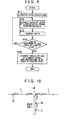
- FIG. 8 shows the flowchart representing the entire process for operating the calculation section 15 in accordance with the updating data generation program PG3 and the updating data transmission program PG4.
- FIG. 9 shows the flowchart representing the detailed process for generating the road map data RDr after updating in step #02 in FIG. 8 .
- the flowchart shown in FIG. 8 will be described.
- the calculation section 15 When the original map data D1 are updated upon reception of the input data from the updating input section 16 (Yes in step #01), the calculation section 15 generates the road map data RDr after updating based on the original map data D1 in accordance with the updating data generation program PG3.
- the detailed explanation of the process in step #02 will be described later referring to the flowchart shown in FIG. 9 .
- the generated road map data RDr after updating are the same as the reference map data D2 and the road map data RD stored in the map database 2 of the navigation device 1 as well as the same format except that they are updated in accordance with the updated content of the original map data D1.
- the updated road map data RDr generated in step #02 are temporarily stored in the memory 17.
- the calculation section 15 makes a comparison between the updated road map data RDr and the reference map data D2 stored in the reference map database 13 in accordance with the updating data generation program PG3 to generate the updating data file Df (step #03).
- the updated road map data RDr and the reference map data D2 have the common data contents except the difference between data before and after updating of the original map data D1 so as to be compared based on the same data format.
- the difference data of the updated road map data RDr in reference to the reference map data D2 are extracted and combined to generate the updating data file Df.
- the calculation section 15 stores the updating data file Df generated in step #03 in the updating database 14 (step #04). Then it is determined whether or not it is possible to communicate between the communication section 18 and the navigation device 1 (step #05). The communication section 18 communicates with the navigation device 1 via the communication network 19 and the wireless base station 20 as described above. When it is determined that the communication is possible (Yes in step #05), the calculation section 15 transmits the updating data file Df to the navigation device 1 via the communication section 18 (step #06). Then the calculation section 15 updates the reference map data D2 based on the updated road map data RDr (step #07). The process performed in the map updating server unit 11 ends. Upon reception of the updating data file Df, the navigation device 1 allows the calculation section 3 to be operated in accordance with the updating program PG2 for updating the road map data RD in the map database 2 (see FIG. 1 ).
- the calculation section 15 converts the data structure of the original map data D1 into the same structure as the road map data RD, that is, the structure having the map data at plural levels and layered structure of the road network data Rn (Rn1 to Rn3) for the map data at the respective levels in accordance with the updating data generation program PG3 (step #11).
- the data of the respective links L at the lowest level 1 are extracted from the converted data (step #12).
- the link IDs are assigned to the respective extracted links L (step #13).
- the extracted link L is provided with the link ID with the numerical range set in accordance with the link length of the link L and the road attribute and set to be sequential in the connection order in the link string ML at each link string having plural links L connected in line as the exclusive ID (identifier) for identification without being overlapped.
- the rule for setting the link ID which has been already described before will not be explained herein.
- the new link ID generated by dividing the link ID before updating is assigned as that of the link L to be divided by updating the road network data Rn resulting from the updating of the original map data D1.
- the same link ID as that of the reference map data D2 may be used for the updated road map data RDr.
- FIG. 10 shows the exemplary case where a new node N' and a link string ML5 are added to the existing link L with the link ID of "325-25" shown in FIG. 4 as indicated by the bold line.
- the link ID of the existing link L it is preferable to divide the link ID of the existing link L to generate the respective link IDs for the divided links L.
- the numerical range R of the link ID of the divided link L is obtained by calculation of the aforementioned equation (1). For example, in the case where the existing link L with the link length of 130 m, the numerical range R of "26", and the link ID of "325-25" shown in FIG. 4 is divided into the former section of the link string ML (left side shown in FIGS.
- the numerical range R of the link ID prior to the division is "26"
- the numerical range R of the link ID of the link L with the link length of 50 m after the division becomes "10"
- the former side of the link ID after division becomes "325-15” and the latter side of the link ID becomes "341-9" as shown in FIG. 10 .
- the links L which form the added link string ML5 are set such that the link IDs which are not overlapped with those of the links L which form the existing link strings ML1 to ML4 are sequentially arranged in the connection order in the link string ML 5.
- "600-23” and “624-18" are set as the link ID as the example.
- step #13 After the link IDs are assigned to the respective links L (step #13), it is determined whether or not the link IDs have been assigned to all the links L at the level 1 as the lowest level (step #14). The process in steps #12 and #13 will be repeatedly executed (No in step #14) until the link IDs are assigned to all the links L at the level 1.
- step #15 the link IDs of the links L at the level 1 as the lowest level are combined, and the link IDs for the respective links at the levels 2 and 3 as the higher levels are assigned (step #15).
- the process for generating the road map data RDr after updating ends.
- the road map data structure according to the present invention is applicable to the use as the navigation device, the map database and the like.
- each link of the road network data is provided with a link ID which includes a numerical range set in accordance with a link length of the link and a road attribute to be sequentially arranged in a connection order in a link string by the respective link strings each having plural links connected in line.
Landscapes
- Engineering & Computer Science (AREA)
- Radar, Positioning & Navigation (AREA)
- Remote Sensing (AREA)
- Automation & Control Theory (AREA)
- Physics & Mathematics (AREA)
- General Physics & Mathematics (AREA)
- Databases & Information Systems (AREA)
- Navigation (AREA)
- Traffic Control Systems (AREA)
- Instructional Devices (AREA)
Abstract
Description
- The present invention relates to a structure of road map data used in a navigation device, for example, and more particularly, to a road map data structure which contains the road network data representing roads in connection with plural links, a road map data storage medium which stores the road network data, and a navigation device using the road map data storage medium.
- In the field relevant to the navigation device, the art for displaying the self location and guiding the route to the destination by means of the road map data as the digital data representing the information with respect to the actual road has been known. Generally, such road map data contain road network data at plural levels corresponding to the level of detail or the scale for the display of the road information to be stored. The respective road network data at the corresponding level represent the road in connection with the plural links. As a link ID for identifying the link which forms the road network data, generally, link IDs are sequentially provided in the order of the connection in a link string by the respective link strings including plural successive links each having the common attribute. The link ID structured to have a predetermined numerical range which contains plural successive numbers is known. There has been also known that the range proportional to each link length of the respective links is set to the numerical range of the link ID as disclosed in
Japanese Patent No. 3725022 Japanese Patent Application Publication No. JP-A-2005-70482 - In the road map data structure as described above, the link ID has a predetermined numerical range. When updating the road network data by dividing the existing link into plural sections for connecting a new link to the intermediate point of the existing link, the continuity of the link ID sequentially arranged in the order of connection may be maintained. In the aforementioned case, the numerical range of the link ID of the existing link is divided to newly generate plural link IDs so as to be assigned to the respective divided sections of the existing link. This makes it possible to easily update for adding the new link while maintaining the continuity of the link ID.
- In the aforementioned road map data structure, many links which form the road network are required to be identified by the link IDs. In order to allow the respective link IDs to have the respective numerical ranges, the digit number used as the link ID becomes inevitably more than the one in the case where the numerical range is not provided. As the numerical range is set to be wider for ensuring large number of division of the link for updating the road network data as described above, the digit number is increased. As the digit of the numerical range of the link ID is increased, the data bit number representing the link ID is required to be large, thus making the data size for representing the link ID unnecessarily large. In the case where each numerical range of the respective link IDs is set to be small for reducing the digit number thereof, multiple division of the specific link is not allowed for the prospective updating of the road network data, thus failing to maintain the continuity of the link ID.
- It is an object of the present invention to provide a road map data structure capable of appropriately setting the numerical range of each link ID of the respective links, ensuring sufficient number of times for dividing the respective links while maintaining the continuity of the link ID for the prospective updating, and allowing reduction in the data size for representing each link ID of the respective links as small as possible, a road map data storage medium which stores the road map data structure, and a navigation device using the road map data structure and the road map data storage medium.
- This object is solved by a road map data structure according to claims 1 a road map data storage medium according to
claim 7 and a navigation device according to claim 8, respectively. Advantageous embodiments are shown in the dependent claims. - A road map data structure according to the present invention is provided with road network data which represent a road in connection with plural links, and a link ID is assigned to each of the links of the road network data, and the link ID has a numerical range set in accordance with both a link length of the link and a road attribute, and further is sequentially set in a connection order within a link string for the each link string composed of the plural links connecting in line.
- In the aforementioned road map data structure, the numerical range of the link ID of the link with a road attribute with high possibility to be divided accompanied with the addition of the new link upon prospective updating of the road network data with respect to the link length is set to be wide depending on the road attribute of the link. This ensures sufficient number of times for dividing the subject link while maintaining the continuity of the link ID. Meanwhile, the numerical range of the link ID with respect to the link length with the road attribute having the low possibility to be divided is set to be small. This makes it possible to suppress the total numerical range of the link ID required for identifying all the links which form the road network as small as possible, thus reducing the digit number of each numerical range of the respective link IDs. This also makes it possible to realize the road map data structure capable of performing sufficient number of times for dividing the link depending on the road attribute of the link while maintaining the continuity of the link ID for the prospective updating, and capable of suppressing the data size for representing each link ID of the respective links as small as possible.
- The road attribute includes at least one of a category attribute with respect to a road category of the link, and an area attribute with respect to an area where the link exists.
- In the aforementioned structure, the numerical range of the link ID may be appropriately set depending on at least one of the road category of the respective links and the area where the respective links exist, which may greatly influence the possibility of dividing the link accompanied with the updating of the road network data.
- The numerical range of the link ID is set based on a value obtained by multiplying the link length of the link by an attribute coefficient determined in accordance with the road attribute of the link.
- The aforementioned structure allows the numerical range of the link ID to be appropriately set depending on the link length and the road attribute of the respective links.
- The attribute coefficient is preliminarily set for each of plural attribute sections divided in accordance with the road attribute, and the setting of the attribute coefficient is based on a possibility of link division a cause of update of the road network data on the each of the attribute sections.
- In the aforementioned structure, as the possibility of dividing the link accompanied with updating of the road network data becomes high, the numerical range of the link ID with respect to the link length may be set to be wide. This ensures sufficient number of times for dividing the link while maintaining the continuity of the link ID, and allows the total numerical range of the link ID required for identifying all the links which form the road network data to be reduced as small as possible. This makes it possible to realize the road map data structure capable of reducing the size of data for representing the link IDs of the respective links as small as possible.
- The attribute section includes at least three category attribute sections of a main road of highway, a side road of highway and a general road; and the attribute coefficient of the category attribute section is made larger in the order of the main road of highway, the side road of highway and the general road.
- In the aforementioned case, the possibility of dividing the link corresponding to the main road of highway accompanied with updating of the road network data is low as the new road is not connected to the main road of highway unless the interchange, service area, parking area and the like are newly built. Meanwhile, the possibility that the new road is connected to the general road is relatively high. The possibility that new road is connected to the interchange, service area, parking area, and the side road to the highway, for example, the guide path connected to the main road of the highway is higher than the possibility in case of the main road of highway, and is lower than the possibility in case of the general road. Accordingly, the structure allows the numerical range of the link ID to be appropriately set depending on the possibility of dividing the link based on the road category thereof.
- The attribute section includes at least two area attribute sections of an urban area and a local area; and the attribute coefficient of the area attribute section is made larger in the order of the local area and the urban area.
- The frequency of updating the road in the urban area is higher than that of updating the road in the local area. The possibility of dividing the link accompanied with updating of the road network data resulting from connection of the new road is relatively high. Accordingly, the structure allows the numerical range of the link ID to be appropriately set depending on the possibility of dividing the link based on the area where the link exists.
- The road map data having the road map data structure with aforementioned structure is stored in the storage medium and preferably used as the road map data storage medium.
- A navigation device according to the present invention includes a map database which stores road map data having the aforementioned structure, a self location detection unit for detecting a self location, an application program operated in reference to the road map data; and a guide information output unit operated in accordance with the application program for outputting guide information.
- The aforementioned structure allows the map database of the navigation device to be provided with the road map data capable of ensuring sufficient number of times for dividing each link depending on the road attribute of the link while maintaining the continuity of the link ID for the prospective updating of the road network data, and capable of suppressing the size of data for representing the link ID of the link as small as possible. Accordingly, the road network data may be appropriately updated, and the continuity of the link ID may be maintained even after the updating. The resultant navigation device prevents the speed of the processing relative to reading of the road map data from being lowered.
-
-
FIG. 1 is a block diagram schematically showing a structure of a navigation device according to an embodiment of the present invention; -
FIG. 2 is an explanatory view showing the layer structure including plural sections which form the road map data; -
FIG. 3 is a view showing the correlation of the road network data among plural levels of the road map data; -
FIG. 4 is a view showing an exemplary setting of each link ID of links which form the road network data at the respective levels; -
FIG. 5 is a view showing exemplary data of the category attribute coefficients corresponding to the respective attribute sections; -
FIG. 6 is a view showing exemplary data of the area attribute coefficients corresponding to the respective attribute sections; -
FIG. 7 is a block diagram schematically showing the structure of the map updating server unit according to the embodiment of the present invention; -
FIG. 8 is a flowchart showing the entire process for generating and transmitting the update data in the map updating server unit; -
FIG. 9 is a flowchart showing the process for generating the road map data after the updating in detail; and -
FIG. 10 is a view showing an exemplary setting of the link ID. - An embodiment of the present invention will be described referring to the drawings.
FIG. 1 is a block diagram schematically showing the structure of anavigation device 1 according to the embodiment. Thenavigation device 1 is structured to perform general navigation functions for displaying the self location, searching the route from the current position to the destination, guiding the route to the destination, retrieving the destination and the like. Referring toFIG. 1 , thenavigation device 1 is formed of a map database 2, acalculation section 3, a selflocation detection section 4, amemory 5, acommunication section 6, adisplay input section 7, and a voice output section 8. The respective function sections of thenavigation device 1 are formed by mounting the hardware and/or the software (program) for executing various types of the process with respect to the input data, having thecalculation section 3 formed of the CPU (Central Processing Unit) as the core component. - The map database 2 stores road map data RD to which the
calculation section 3 refers in accordance with the application program PG1 to be described later. The map database 2 has a hardware structure including a writable storage medium such as a hard disk drive and the flash memory, and a drive unit for driving the storage medium. In the embodiment, the map database 2 corresponds to the "road map data storage medium" which stores the road map data RD according to the present invention. The road map data RD stored in the map database 2 has the data structure according to the present invention. Besides the road mp data RD, the map database 2 stores various data (guiding data) for displaying, guiding, searching so as to be used in the application program PG1, which are not shown in the drawing. More specifically, the aforementioned data include image data, voice data, POI (Point of Interest) and the like, each data of which are stored in correlation with the link and node (seeFIG. 3 ) contained in the road map data RD. The structure of the road map data RD will be described in detail referring toFIGS. 2 and3 . -
FIG. 2 is an explanatory view showing the layer structure with respect to plural sections p which form the road map data RD. Referring to the drawing, the road map data RD includes plural levels, and the map data at the respective levels are divided into plural sections p corresponding to the level. As the level becomes high, the section p corresponds to the wider area. The section p at the high level contains the area corresponding to the plural sections p at the lower level. In the embodiment, the road map data RD includes four levels from the lowest level 0 to thehighest level 3. The map data at the lowest level 0 form the map of the urban area, which is used for showing the road in the urban area in detail to cover the specific area. The map data at thelevel 1 as the lowest level cover the entire area. The map data at the level from 1 to 3 include road network data Rn used for the route search and the like, respectively. -
FIG. 3 shows the correlation of the road network data Rn among therespective levels 1 to 3 of the road map data RD. Referring to the drawing, in the road map data RD, the map data at the plural levels in accordance with the detail level and the display scale of the road information to be stored are provided with road network data Rn (Rn1 to Rn3) in the layer structure. The road network data Rn at the respective levels graphically represent the actual road in connection with the plural links L. In the embodiment, the road network data Rn have three levels from thelowest level 1 to thehighest level 3. The single section p at the high level contains the area corresponding to the plural sections p at the lower level. The road network data Rn at the respective levels are structured such that plural links L are connected with one another via nodes N at the respective ends of the links L. Each of the nodes N is set corresponding to the intersection on the actual road. Each of the links L is set corresponding to the road between the respective intersections. When the link L goes beyond the boundary of the section p, the dummy node is set on the boundary of the subject section p irrespective of the intersection on the actual road. The node N includes two types, that is, the actual node set corresponding to the intersection on the real road, and the dummy node virtually set on the boundary of the section irrespective of the actual intersection. In the embodiment, both nodes will be generically referred to as the node N. - In the embodiment, the road network data Rn at the respective levels will be generically referred to as the "Rn". The road network data may be coded as "Rn1" to "Rn3" corresponding to the
levels 1 to 3 for the purpose of distinguishing the level. As the level of the road network data Rn becomes lower, the road information becomes more detail. In the embodiment, the road network data Rn1 at thelowest level 1 contains the information with respect to the roads which covers the entire road category of the road map data, for example, the highway (including the main road and side road), national road, principal prefectural road, prefectural road, other main numbered road, narrow street and the like. The road network data Rn2 and Rn3 at thelevels 2 and 3 contain no information with respect to the road with the category regarded as insignificant for searching the route (for example, narrow street). - The information data representing the nodes N and links L of the road network data Rn are arranged by the respective link strings ML (multi link) (see
FIG. 4 ) each having the common road attribute and formed of plural links connected in a line in the order of connection in the link string ML at the respective levels (1 to 3). In the embodiment, the name of the actual road, for example, "national road 1", "Meishin Expressway" is used as the common road attribute which specifies the respective link string ML. The link L corresponding to the road with the same name is maintained to form the long link string ML within the section p. The common road attribute which specifies the respective link string ML is not limited to the road name, but various road attributes with respect to the road or the link, for example, the road category, number of lanes, road width and the like may be employed. - The road network data Rn contains attribute information data with respect to the link L and the node N by each link string ML. The attribute information of the node N contains the coordinate information showing the coordinate of the node N, the information showing whether the dummy node or the actual node, the information showing the traffic regulation, the information showing the upper limit level where the respective nodes N exist (
levels 1 to 3), the information showing presence or absence of the traffic light and the like. The attribute information of the link L contains the link ID information showing the link ID of the respective link (described later), the configuration information showing the configuration of the link L, the information showing the traffic regulation, the information showing the road category, the road name information, the information showing the road width, the information of the number of lanes, the information of the upper limit level (levels 1 to 3) where the links L exist and the like. - The link ID is assigned to each of the links L in the road map data RD as an exclusive ID (identifier) for identifying the respective links so as not to be overlapped. The road map data RD are structured to have the numerical range for the respective links L of the road network data Rn, which may be set in accordance with the link length of the link L and the road attribute, and to have the link ID which is set to be sequential in the order of connection in the link string ML by the respective link strings ML each having the plural links L connected in the single line. The structure of the aforementioned link ID will be described in detail.
-
FIG. 4 shows an exemplary setting of the link IDs of the respective links L which form the road network data Rn1 to Rn3 at the respective levels. Referring to the drawing, a predetermined numerical range including plural successive numbers is assigned to the link ID of the link L. The link ID with the numerical range is represented by combining the first number and the difference between the first and the last numbers of the link ID. In the case where the numerical range of the link ID is expressed as "100-13", the number "100" is the first number, and the "13" is the difference between the first and the last numbers. Accordingly, the sequential numerals ranging from 100 to 113 (natural numbers herein) with the numerical range of "14" is assigned as the link ID. The rule for setting the numerical range of the link ID will be described in detail later. In the example shown inFIG. 4 , the link string ML formed of plural links L connected in line includes a first link string ML1, a second link string ML2, a third link string ML3, and a fourth link string ML4. In the explanation with respect to the embodiment, the respective link strings are genetically referred to as the code "ML". The codes of "ML1" to "ML4" will be used for distinguishing the respective link strings ML. - Each of the link IDs of the respective links L is set to be sequential with respect to the strings ML1 to ML4 in the order of connection therein. The link IDs of the respective links L in the first link string ML1 of the road network data Rn1 at the
level 1 includes "100 - 13", "114-12", "127-9", and "137-16" sequentially from the head of the link L (the leftmost link L shown inFIG. 4 ). The aforementioned link IDs may be expressed as the numerals as "100-113", "114-126", "127-136", and "137-153", respectively. The link IDs are set such that the numbers are sequentially arranged in the order of connection in the link string ML1. In the road network data Rn2 and Rn3 at thelevels 2 and 3 higher than thelevel 1, the plural links L at the lower level are combined into the single link L. The link ID of the thus combined link L is set as the one obtained by combining the link IDs of the respective links L before the combination. For example, in the first link string ML1 of the road network data Rn2 at the level 2, the link ID of the link L at the level 2 is formed by combining two links L each having the link ID from"100-13" and "114-12" at thelevel 1 to "100-26" at the level 2. The link ID of the link L at the level 2 is formed by integrating two links L each having the link ID of "127-9" and "137-16" at thelevel 1 to "127 to 26" at the level 2. The aforementioned structure of the link ID allows the link L at the lower level to be easily correlated with the link L at the higher level based on the link ID. - The rule for setting the numerical range of the link ID will be described. In the embodiment, the numerical range of the link ID is set based on the value obtained by multiplying each link length of the links by the attribute coefficient determined by the road attribute of the link. In the embodiment, the category attribute with respect to the road category, and the area attribute with respect to the area where the respective links exist are used as the road attribute for setting the numerical range of the like ID. In the embodiment, the category attribute coefficient Ca determined in accordance with the category attribute and the area attribute coefficient Cb determined in accordance with the area attribute are used as the attribute coefficients. The numerical range R of the link ID is obtained by calculation of the following equation (1).

where "S" denotes the reference number representing the reference numerical range per a unit link length. In the embodiment, the reference number S is set in reference to the numerical range suitable for the link L under the condition where the category attribute is the "general road", and the area attribute is "urban area" to be described later. For example, the reference number may be set to "20" per link length of 100 m. The "LL" denotes the link length indicating the information of the one corresponding to the actual length of the link L. As described above, the link length information is contained in the road network data Rn as the attribute information of the respective links L. - The link ID of the link L is determined by the numerical range R obtained by the aforementioned equation (1) and the first number. In the case where the first number is "100", and the numerical range R is "14", the link ID becomes "100-13". The first number of the link ID is the number (natural number) subsequent to the last number of the link ID of the link L as the previous one to which the subj ect link L is connected in the link string ML where the link L exists. In other words, the first number of the link ID of the link L subsequent to the one having the link ID of "100-13" becomes "114". In the link L at the head of the link string ML, the first number of the link ID is set such that the link IDs of all the links L which form the link string ML are not overlapped with those in the other link string ML. In the embodiment, the numerical range of the link ID is set with respect to the road network data Rn1 at the
level 1 as being the lowest based on the aforementioned rule. The link ID formed by integrating the link IDs of the link L at thelevel 1 may be assigned to the road network data Rn2 and Rn3 at thehigher levels 2 and 3, respectively. - The category attribute coefficient Ca and the area attribute coefficient Cb as the attribute coefficients are preliminarily set for plural attribute sections divided in accordance with the respective road attributes (category attribute or area attribute). The category attribute coefficient Ca and the area attribute coefficient Cb are set to values determined in accordance with the possibility that the link L is divided by updating of the road network data Rn with respect to the respective attribute sections.
FIG. 5 is a view showing exemplary attribute sections and corresponding category attribute coefficients Ca.FIG. 6 is a view showing exemplary attribute sections and corresponding area attribute coefficients Cb. - Referring to
FIG. 5 , in the embodiment, the road category is divided into three sections, that is, "main road of highway", "side road of highway", and "general road" as category attribute section with respect to the category attribute. The category attribute coefficients Ca of the respective category attribute sections are set to the values which become larger in the order of the "main road of highway", "side road of highway", and "general road", that is, "0.3", "0.6", and "1", respectively. The section of the "main road of highway" includes the link L which forms the main road of the highway and toll road. The section of the "side road of highway" includes the link L which forms the interchange, the service area, and the parking area, and the guide path for connecting the main road of highway to the aforementioned facilities. The section of the "general road" includes all the links L which do not belong to the sections of the "main road of highway" and the "side road of highway". More specifically, the link L for forming the national road, principal prefectural road, prefectural road, other main numbered road, and the narrow street are contained. The new road is not connected to the road of the category belonging to the section of the "main road of highway" unless the interchange, service area, parking area and the like are newly built. Accordingly, the possibility that the link L belonging to the aforementioned section is divided by updating of the road network data Rn is low. The possibility that the road is newly connected to the road of the category belonging to the "general road" is relatively high. The possibility that the road is newly connected to the road of the category belonging to the "side road of highway" is at the medium level between the levels of the "main road of highway" and the "general road". Depending on the possibility that the link L is divided by updating of the road network data Rn with respect to the category attribute section, the category attribute coefficient Ca is set to the larger value as the possibility becomes high. - Referring to
FIG. 6 , in the embodiment, the area is divided into two sections, that is, "urban area" and "local area" as the area attribute section with respect to the area attribute. The area attribute coefficients Cb for the area attribute section are set to the larger values in the order of the "local area" and "urban area", that is, "0.7" and "1", respectively. In the embodiment, the determination whether the link L belongs to the "urban area" section or the "local area" section may be made based on presence/absence of at least a part of the link L is contained in the area on the map which has the map data for forming the urban area map at the level 0. The determination may be easily made based on the urban area map which covers only the part of the urban area rather than the entire area of the road map data RD. Generally, the frequency of updating the road belonging to the "urban area" section is higher than that of updating the road belonging to the "local area" section. The possibility that the link is divided by updating of the road network data resulting from newly connected road becomes relatively high. The area attribute coefficient Cb is set to the larger value as the possibility that the link L is divided by updating of the road network data Rn with respect to the area attribute section becomes high. - In the example shown in
FIG. 4 , the category attribute sections of the link L which forms the respective link strings ML include the "main road of highway" as the first link string ML1, the "side road of highway" as the second link string ML2, the "general road" as the third link string ML3, and the "side road of highway" as the fourth link string ML4. The fourth link string ML4 forms the service area and the guide path connected thereto, which is provided in parallel with the "main road of highway" as the first link string ML1. The second link string ML2 forms the interchange and the guide path connected thereto, which is provided in series with the "main road of highway" as the first link string ML1. Assuming that the reference number S is "20" per link length of 100 m in the equation (1) under the condition where all the links L that form the first to the fourth link strings ML1 to ML4 belong to the "urban area" section, the numerical range R of the link ID of the link L with the link length of 220 m on the first link string ML1 may be obtained by calculation of the following equation (2).
- In the embodiment, the obtained value is rounded to the numerical range R as the natural number. Accordingly, the obtained numerical range R is "13". In the case where the last number of the link ID of the link L preceding the one connected to the link L is "113", the link ID becomes "114 -12".
- Under the same condition as described above, the numerical range R of the link ID of the link L with the link length of 100 m in the third link string ML3 may be obtained by calculation of the following equation (3).

- In the case where the last number of the link ID of the link L preceding the one connected to the link L is "373", the link ID becomes "373- 19".
- The numerical range of the link ID is set with respect to at least the road network data Rn1 at the
level 1 as the lowest level in accordance with the aforementioned rule. The link ID obtained by combining the link IDs of the links L at thelevel 1 is assigned to the road network data Rn2 and Rn3 at thehigher levels 2 and 3. The link ID having the numerical range set in accordance with the link length of the link L and the road attribute to be sequentially arranged in the order of the connection in the link string ML by each of the link strings ML including plural links L which are connected in line may be assigned to the respective links L of the road network data Rn, that is, Rn2 and Rn3 at the higher levels. - The
calculation section 3 functioning as the calculation unit operated in accordance with the application program PG1 stored in thememory 5 is formed of the known calculation unit such as CPU. The application program PG1 contains such programs as the display program, map matching program, route search program, guide program, and retrieving program, which are not shown. The display program displays the self location and the map around the destination on the display screen of thedisplay input section 7 as well as displays the self location on the displayed map. The map matching program is intended to execute the map matching process for matching the self location detected by the selflocation detection section 4 at the road on the map. The route search program is intended to execute the route searching for searching the route guide to the destination input through thedisplay input section 7 from the starting point such as the self location. The guide program is intended to execute the process for guiding the user with respect to the appropriate route with the aid of the guide displayed on the display screen on thedisplay input section 7 and the voice guide through the voice output section 8 in accordance with the route to the destination determined by the route search program. The retrieving program is intended to retrieve the destination or the point for displaying the map based on the address, phone number, facility name, category and the like. The operation performed by thenavigation device 1 through thecalculation section 3 activated based on the aforementioned programs is well known, and the explanation thereof, thus will be omitted. Thecalculation section 3 activated in accordance with the application program PG1 refers to the road map data RD stored in the map database 2 as the map information. - The
memory 5 stores the updating program PG2 which allows thecalculation section 3 to execute updating of the road map data RD based on the updating data file Df (seeFIG. 7 ) supplied from the map updatingserver unit 11 which will be described later. In the embodiment, the updating data file Df is formed by combining the updating data with respect to the road map data RD stored in the map database 2, as described later. The road map data RD may be updated by replacing the portion of the road map data RD to be updated with the data contained in the updating data file Df. - The self
location detection section 4 functions in detecting the self location of thenavigation device 1. The selflocation detection section 4 includes a GPS receiver, a directional sensor, and a distance sensor (not shown). The information with respect to the coordinate indicating the current location and the traveling direction is obtained based on the information derived from the aforementioned detectors so as to be output to thecalculation section 3. In the embodiment, the selflocation detection section 4 corresponds to the "self location detection unit". - The
display input section 7 is formed of a display screen, for example, a liquid crystal display unit and the like, and a touch panel or an operation switch operated in conjunction with the display screen. The voice output section 8 is formed of a speaker and an amplifier. Thedisplay input section 7 and the voice output section 8 are connected to thecalculation section 3 so as to display and output the voice for the self location display, the route search between two points, route guidance, and the retrieval of the destination in accordance with the operation of thecalculation section 3. Thedisplay input section 7 receives the input operation of the user to output the input content to thecalculation section 3. In the embodiment, thecalculation section 3, thedisplay input section 7 and the voice output section 8 correspond to the "guideinformation output unit 9" according to the present invention. - The
communication section 6 serves to perform communication with a map updatingserver unit 11 to be described later. In the embodiment, thecommunication section 6 is structured to be allowed to wirelessly receive and transmit data with a wireless base station 20 (seeFIG. 7 ). As the wireless communication method, the known communication network, for example, portable phone network, wireless LAN (Local Area Network) and the like may be employed. As shown inFIG. 7 , thecommunication section 6 is structured to be capable of communicating with the map updatingserver unit 11 via thewireless base station 20 and thecommunication network 19 such as the internet. Thenavigation device 1 is allowed to receive the updating data file Df transmitted from the map updatingserver unit 11. Preferably thecommunication section 6 is structured to be allowed to perform wired or wireless communication with the updating terminal owned by the user or the dealer of thenavigation device 1, which is not shown in the drawing. Thenavigation device 1 may be structured to be able to receive the updating data file Df transmitted to the updating terminal via the communication network. - The structure of the map updating
server unit 11 which delivers the updating data file Df for updating the road map data RD in thenavigation device 1 will be described hereinafter.FIG. 7 is a block diagram schematically showing the structure of the map updatingserver unit 11. In the embodiment, the map updatingserver unit 11 generates the updating data file Df based on anoriginal map database 12 which stores original map data D1 to be updated by the input data from the updatinginput section 16, and areference map database 13 which stores reference map data D2 having the same contents as those of the road map data RD in the map database 2 of thenavigation device 1. The map updatingserver unit 11 stores the generated updating data file Df in an updatingdatabase 14 to deliver the updating data file Df to thenavigation device 1 upon communication therewith via acommunication section 18. Referring toFIG. 7 , the map updatingserver unit 11 includes theoriginal map database 12, thereference map database 13, the updatingdatabase 14, acalculation section 15, an updatinginput section 16, amemory 17, and thecommunication section 18. The aforementioned function units of the map updatingserver unit 11 is formed by having the function units for performing various process with respect to the input data combined with at least one of the hardware or the software (program) using thecalculation section 15 formed of the CPU (Central Processing Unit) as the core member. Structures of the respective units will be described. - The original
map data D 1 stored in theoriginal map database 12 contain a data structure representing the respective links L for forming the road network data by combining predetermined link ID and the attribute data. In the embodiment, the permanent ID formed of the number, character, code and the like which is irrelevant to the connection order of the link L in the road network data Rn is employed as the link ID for the original map data D1. The attribute data of the respective links L contain the same information data as those of the link L and the node N contained in the aforementioned road map data RD. The original map data D1 are updated by the input data from the updatinginput section 16. The updatinginput section 16 includes a display unit, for example, the monitor, and an input device, for example, keyboard, mouse and the like, and is structured to display the content of the original map data D1 via thecalculation section 15, and allow the user to input the new road map information to be updated with the input device while confirming the content of the original map data D1. The user is allowed to update the content of the original map data D1 via the updatinginput section 16 based on the information with respect to the change in the road derived from the field work and the aerial photo. - The reference map data D2 stored in the
reference map database 13 have the same contents as those of the road map data RD stored in the map database 2 of thenavigation device 1. Likewise the road map data RD, the reference map data D2 contain the map data at plural levels with the layered structure including the road network data Rn (Rn1 to Rn3) in the map data at the respective levels. Likewise the road map data RD, each of the links L in the reference map data D2 is provided with the link ID having the numerical range set in accordance with the link length of the link L and the road attribute to be sequential in the connection order in the link string ML by the respective link strings ML each having the plural links L connected in line as the exclusive ID (identifier) for identification without being overlapped. The further explanation which has been already described will be omitted. The contents of the reference map data D2 are updated so as to match the content of the road map data RDr updated based on the updated original map data D1 after generating the updating data file Df. In this way, the content of the reference map data D2 may be constantly maintained to be the same as that of the road map data RD of thenavigation device 1 to be updated by the updating data file Df. In the embodiment, thereference map database 13 corresponds to the "road map data storage medium" which stores the road map data RD according to the present invention. - The updating data file Df stored in the updating
database 14 is formed by combining the updating portion of the road map data RD stored in the map database 2 into the single file. The updating data file Df is generated by thecalculation section 15 operated in accordance with the updating data generation program PG3 stored in thememory 17, and stored in the updatingdatabase 14. In the embodiment, the updating data file Df is formed as the extracted difference data file through the comparison between the updated road map data RDr generated based on the original map data D1 and the reference map data D2 stored in thereference map database 13. - The
calculation section 15 functions to calculate in accordance with the updating data generation program PG3 and the updating data transmission program PG4 stored in thememory 17, and is formed of the known calculation unit such as the CPU. The updating data generation program PG3 is intended to generate the updating data file Df based on the updated original map data D1 and the reference map data D2 upon updating of the original map data D1. The updating data transmission program PG4 is intended to transmit the updating data file Df generated in accordance with the updating data generation program PG3 to thenavigation device 1. The process for operating thecalculation section 15 in accordance with those updating data generation program PG3 and the updating data transmission program PG4 will be described in detail referring to the flowcharts shown inFIGS. 8 and9 . - The
communication section 18 functions to communicate with thenavigation device 1. In the embodiment, thecommunication section 18 is structured to be able to communicate with thenavigation device 1 via thecommunication network 19 such as the internet and thewireless base station 20. Thecommunication section 18 is allowed to transmit the updating data file Df to thenavigation device 1. - The process for operating the
calculation section 15 executed in the map updatingserver unit 11 in accordance with the updating data generation program PG3 and the updating data transmission program PG4 will be described referring to the flowcharts shown inFIGS. 8 and9 .FIG. 8 shows the flowchart representing the entire process for operating thecalculation section 15 in accordance with the updating data generation program PG3 and the updating data transmission program PG4.FIG. 9 shows the flowchart representing the detailed process for generating the road map data RDr after updating instep # 02 inFIG. 8 . - The flowchart shown in
FIG. 8 will be described. When the original map data D1 are updated upon reception of the input data from the updating input section 16 (Yes in step #01), thecalculation section 15 generates the road map data RDr after updating based on the original map data D1 in accordance with the updating data generation program PG3. The detailed explanation of the process instep # 02 will be described later referring to the flowchart shown inFIG. 9 . The generated road map data RDr after updating are the same as the reference map data D2 and the road map data RD stored in the map database 2 of thenavigation device 1 as well as the same format except that they are updated in accordance with the updated content of the original map data D1. The updated road map data RDr generated instep # 02 are temporarily stored in thememory 17. Thecalculation section 15 makes a comparison between the updated road map data RDr and the reference map data D2 stored in thereference map database 13 in accordance with the updating data generation program PG3 to generate the updating data file Df (step #03). Specifically, the updated road map data RDr and the reference map data D2 have the common data contents except the difference between data before and after updating of the original map data D1 so as to be compared based on the same data format. The difference data of the updated road map data RDr in reference to the reference map data D2 are extracted and combined to generate the updating data file Df. - The
calculation section 15 stores the updating data file Df generated instep # 03 in the updating database 14 (step #04). Then it is determined whether or not it is possible to communicate between thecommunication section 18 and the navigation device 1 (step #05). Thecommunication section 18 communicates with thenavigation device 1 via thecommunication network 19 and thewireless base station 20 as described above. When it is determined that the communication is possible (Yes in step #05), thecalculation section 15 transmits the updating data file Df to thenavigation device 1 via the communication section 18 (step #06). Then thecalculation section 15 updates the reference map data D2 based on the updated road map data RDr (step #07). The process performed in the map updatingserver unit 11 ends. Upon reception of the updating data file Df, thenavigation device 1 allows thecalculation section 3 to be operated in accordance with the updating program PG2 for updating the road map data RD in the map database 2 (seeFIG. 1 ). - The process for generating the road map data RDr updated in
step # 02 will be described in detail referring to the flowchart shown inFIG. 9 . Thecalculation section 15 converts the data structure of the original map data D1 into the same structure as the road map data RD, that is, the structure having the map data at plural levels and layered structure of the road network data Rn (Rn1 to Rn3) for the map data at the respective levels in accordance with the updating data generation program PG3 (step #11). The data of the respective links L at thelowest level 1 are extracted from the converted data (step #12). The link IDs are assigned to the respective extracted links L (step #13). Specifically, the extracted link L is provided with the link ID with the numerical range set in accordance with the link length of the link L and the road attribute and set to be sequential in the connection order in the link string ML at each link string having plural links L connected in line as the exclusive ID (identifier) for identification without being overlapped. The rule for setting the link ID which has been already described before will not be explained herein. The new link ID generated by dividing the link ID before updating is assigned as that of the link L to be divided by updating the road network data Rn resulting from the updating of the original map data D1. As for the link L which does not change with respect to the reference map data D2, the same link ID as that of the reference map data D2 may be used for the updated road map data RDr. -
FIG. 10 shows the exemplary case where a new node N' and a link string ML5 are added to the existing link L with the link ID of "325-25" shown inFIG. 4 as indicated by the bold line. In the aforementioned case, it is preferable to divide the link ID of the existing link L to generate the respective link IDs for the divided links L. The numerical range R of the link ID of the divided link L is obtained by calculation of the aforementioned equation (1). For example, in the case where the existing link L with the link length of 130 m, the numerical range R of "26", and the link ID of "325-25" shown inFIG. 4 is divided into the former section of the link string ML (left side shown inFIGS. 4 and10 ) with the length of 80 m, and the latter section (left side shown inFIGS. 4 and10 ) with the length of 50 m, the link ID may be set in the following manner. Under the condition where the reference number S in the equation (1) is "20" per the link length of 100 m, and all the links L which form the fourth link string ML1 belong to the "urban area" section, the numerical range R of the link ID for the link L with the link length of 80 m after the division may be obtained as follows.
- As the numerical range R of the link ID prior to the division is "26", the numerical range R of the link ID of the link L with the link length of 50 m after the division becomes "10". The former side of the link ID after division becomes "325-15" and the latter side of the link ID becomes "341-9" as shown in
FIG. 10 . The links L which form the added link string ML5 are set such that the link IDs which are not overlapped with those of the links L which form the existing link strings ML1 to ML4 are sequentially arranged in the connection order in thelink string ML 5. In this case, "600-23" and "624-18" are set as the link ID as the example. - Referring to
FIG. 9 , after the link IDs are assigned to the respective links L (step #13), it is determined whether or not the link IDs have been assigned to all the links L at thelevel 1 as the lowest level (step #14). The process insteps # 12 and #13 will be repeatedly executed (No in step #14) until the link IDs are assigned to all the links L at thelevel 1. When the link IDs have been assigned to all the links L at the level 1 (Yes in step #14), the link IDs of the links L at thelevel 1 as the lowest level are combined, and the link IDs for the respective links at thelevels 2 and 3 as the higher levels are assigned (step #15). After the link IDs are assigned to all the links L contained in the road map data RD, the process for generating the road map data RDr after updating ends. -
- (1) In the aforementioned embodiment, the category attribute with respect to the road category in the respective links and the area attribute with respect to the area where the respective links exist are employed as the road attribute for setting the numerical range of the link ID. The present invention, however, is not limited to the aforementioned process in the embodiment. For example, either the category attribute or the area attribute may only be employed as the road attribute for setting the numerical range of the link ID. The road attribute other than the category attribute and the area attribute may be employed for setting the numerical range of the link ID.
- (2) In the aforementioned embodiment, three sections of "main road of highway", "side road of highway" and "general road" are employed as the category attribute sections with respect to the category attribute, and two sections of "urban area" and "local area" are employed as the area attribute sections with respect to the area attribute. The present invention is not limited to the sections as described above. Preferably the specific sections of the category attribute and the area attribute are set depending on the possibility of dividing the link L by updating of the road network data Rn. Preferably the values of the category attribute coefficient Ca and the area attribute coefficient Cb are appropriately set depending on the possibility of dividing the link L resulting from updating of the road network data Rn as well.
- (3) In the aforementioned embodiment, the link ID is expressed as the combination of the first number of the subject link ID and the difference between the first and the last numbers of the link ID. The structure of the link ID is not limited to the one as described above. The link ID may be expressed as the combination of the first and the last numbers of the numerical range such as "100-113", "114-126", "127-136" and the like.
- (4) In the aforementioned embodiment, updating version with respect to the reference map data D2 and the updating data file Df are not described. In the case where the road map data RD of
plural navigation devices 1 are updated, data of plural versions which contain the reference map data D2 and the updating data file Df of the old version may be stored in thereference map database 13 and the updatingdatabase 14, respectively depending on each updating state of therespective navigation devices 1. There may be the case where all theplural navigation devices 1 do not communicate with the map updatingserver unit 11 frequently, in other words, one of thenavigation devices 1 may have the old road map data without being updated, and the other may have the road map data RD updated by the latest updating data file Df. Preferably, each of the road map data RD, the reference map data D2 and the updating data file Df is provided with the version information for the purpose of updating the road map data RD of all thenavigation devices 1. The updating data file Df with the version newer than that of the road map data RD of thenavigation device 1 may be employed for updating the old road map data RD. This makes it possible to appropriately update the road map data RD depending on each updating state of therespective navigation devices 1. - (5) In the aforementioned embodiment, the structure of the road map data RD according to the present invention is applied to the road map data of the
navigation device 1. The application of the present invention is not limited to the one as described above. The structure is applicable to the road map data for the other use, for example, the map database for retrieving the destination. - The road map data structure according to the present invention is applicable to the use as the navigation device, the map database and the like.
- As described above, in a road map data structure having road network data which express the road in connection with plural links, each link of the road network data is provided with a link ID which includes a numerical range set in accordance with a link length of the link and a road attribute to be sequentially arranged in a connection order in a link string by the respective link strings each having plural links connected in line.
Claims (9)
- A road map data structure provided with road network data (Rn) which represent a road in connection with plural links (L), wherein a link ID is assigned to each of the links of the road network data, and the link ID has a numerical range set in accordance with both a link length of the link and a road attribute, and further is sequentially set in a connection order within a link string (ML) for the each link string composed of the plural links connecting in line.
- The road map data structure according to claim 1, wherein the road attribute includes at least one of a category attribute with respect to a road category of the link, and an area attribute with respect to an area where the link exists.
- The road map data structure according to claim 1 or 2, wherein the numerical range of the link ID is set based on a value obtained by multiplying the link length of the link by an attribute coefficient (Ca) determined in accordance with the road attribute of the link.
- The road map data structure according to claim 3, wherein the attribute coefficient is preliminarily set for each of plural attribute sections divided in accordance with the road attribute, and the setting of the attribute coefficient is based on a possibility of link division a cause of update of the road network data on the each of the attribute sections.
- The road map data structure according to claim 4, wherein:the attribute section includes at least three category attribute sections of a main road of highway, a side road of highway and a general road; andthe attribute coefficient (Ca) of the category attribute section is made larger in the order of the main road of highway, the side road of highway and the general road.
- The road map data structure according to claim 4 or 5, wherein:the attribute section includes at least two area attribute sections of an urban area and a local area; andthe attribute coefficient (Cb) of the area attribute section is made larger in the order of the local area and the urban area.
- A road map data storage medium (2) which stores road map data (RD) having the data structure according to any one of claims 1 to 6.
- A navigation device (1) comprising:a map database (2) which stores road map data (RD) having the data structure according to any one of claims 1 to 6;a self location detection unit (4) for detecting a self location;an application program (PG1) operated in reference to the road map data; anda guide information output unit (9) operated in accordance with the application program for outputting guide information.
- A method comprising:storing road map data (RD) having the data structure according to any one of claims 1 to 6 in map database (2);detecting a self location;operating an application program (PG1) in reference to the road map data; andoperating a guide information output unit (9) in accordance with the application program for outputting guide information.
Applications Claiming Priority (1)
| Application Number | Priority Date | Filing Date | Title |
|---|---|---|---|
| JP2006351618A JP5093562B2 (en) | 2006-12-27 | 2006-12-27 | Navigation device |
Publications (3)
| Publication Number | Publication Date |
|---|---|
| EP1950530A2 true EP1950530A2 (en) | 2008-07-30 |
| EP1950530A3 EP1950530A3 (en) | 2008-09-17 |
| EP1950530B1 EP1950530B1 (en) | 2017-04-26 |
Family
ID=39495732
Family Applications (1)
| Application Number | Title | Priority Date | Filing Date |
|---|---|---|---|
| EP07150022.7A Not-in-force EP1950530B1 (en) | 2006-12-27 | 2007-12-14 | Road map data structure, road map data storage medium and navigation device |
Country Status (4)
| Country | Link |
|---|---|
| US (1) | US7949467B2 (en) |
| EP (1) | EP1950530B1 (en) |
| JP (1) | JP5093562B2 (en) |
| CN (2) | CN103148859A (en) |
Cited By (1)
| Publication number | Priority date | Publication date | Assignee | Title |
|---|---|---|---|---|
| EP2749845A1 (en) * | 2012-12-28 | 2014-07-02 | Hitachi, Ltd. | Map distribution server for automotive navigation systems, map data distribution system, and road difference data production method |
Families Citing this family (19)
| Publication number | Priority date | Publication date | Assignee | Title |
|---|---|---|---|---|
| JP4727245B2 (en) * | 2005-02-08 | 2011-07-20 | 三菱電機株式会社 | Map information processing device |
| JP4546909B2 (en) * | 2005-09-13 | 2010-09-22 | 株式会社日立製作所 | In-vehicle terminal, traffic information system, and link data update method |
| CN101925941B (en) * | 2008-03-26 | 2012-03-28 | 三菱电机株式会社 | Map data creating device and map drawing device |
| JP5558684B2 (en) * | 2008-07-25 | 2014-07-23 | 株式会社デンソー | MAP DATA UPDATE DEVICE, MAP DATA UPDATE PROGRAM, AND MAP DATA UPDATE METHOD |
| JP5440220B2 (en) | 2010-01-29 | 2014-03-12 | 株式会社デンソー | Navigation device |
| US8571793B2 (en) | 2010-01-29 | 2013-10-29 | Denso Corporation | Map data, method for preparing the same, data product containing the same, storage medium containing the same, and navigation apparatus using the same |
| DE102011077945A1 (en) * | 2011-06-22 | 2012-12-27 | Robert Bosch Gmbh | Method for updating digital card used by navigation system of vehicle, involves updating generalization plane of digital card if object is represented by nodes by updating attribute of nodes based on information and reference elements |
| CN103246650B (en) * | 2012-02-01 | 2016-10-05 | 北京四维图新科技股份有限公司 | A kind of road logic model preparation method |
| JP5790571B2 (en) * | 2012-03-30 | 2015-10-07 | 株式会社デンソー | Information processing system |
| CN102809384B (en) * | 2012-08-22 | 2015-11-11 | 北京世纪高通科技有限公司 | A kind of road chain extracting method and device |
| CN103700314B (en) * | 2013-12-23 | 2017-01-18 | 北京掌城科技有限公司 | Position positioning method, device and electronic map |
| GB2526807A (en) * | 2014-06-03 | 2015-12-09 | Here Global Bv | Updating single regions of a navigational database |
| JP6381030B2 (en) * | 2014-12-12 | 2018-08-29 | 株式会社トヨタマップマスター | MAP DATA PROCESSING DEVICE, ITS METHOD, COMPUTER PROGRAM, AND RECORDING MEDIUM CONTAINING THE COMPUTER PROGRAM |
| EP3234626A4 (en) * | 2014-12-18 | 2018-08-22 | Innerspace Technology Inc. | Method and system for sensing interior spaces to auto-generate a navigational map |
| CN108286974B (en) * | 2017-01-09 | 2020-10-30 | 北京四维图新科技股份有限公司 | Intelligent processing method and device for field collection data, and hybrid navigation system |
| CN107192393B (en) * | 2017-07-20 | 2019-11-12 | 南京多伦科技股份有限公司 | A kind of maintenance system and method for road-map-data |
| CN107886535B (en) * | 2017-10-24 | 2020-05-05 | 南京师范大学 | A point load calculation method under the cloud platform considering the constraints of the hierarchical road network |
| CN109792460A (en) * | 2018-12-25 | 2019-05-21 | 深圳辰锐软件开发有限公司 | A kind of file updating method, file updating device and terminal device |
| US11536573B2 (en) | 2019-09-03 | 2022-12-27 | Here Global B.V. | Method, apparatus, and computer program product for generating correspondence between map versions |
Citations (2)
| Publication number | Priority date | Publication date | Assignee | Title |
|---|---|---|---|---|
| JP2005070482A (en) | 2003-08-26 | 2005-03-17 | Mitsubishi Electric Corp | Map data data structure, map data storage medium, map data update method, and map information processing apparatus |
| JP3725022B2 (en) | 2000-12-05 | 2005-12-07 | 松下電器産業株式会社 | Road map data recording method and navigation apparatus |
Family Cites Families (5)
| Publication number | Priority date | Publication date | Assignee | Title |
|---|---|---|---|---|
| JP3665436B2 (en) * | 1996-10-22 | 2005-06-29 | 株式会社ザナヴィ・インフォマティクス | Navigation device |
| US6668227B2 (en) * | 2002-04-10 | 2003-12-23 | Matsushita Electric Industrial Co., Ltd. | Navigation apparatus |
| JP4034113B2 (en) * | 2002-05-10 | 2008-01-16 | 三菱電機株式会社 | Map data update system and map data update program |
| JP2005165045A (en) * | 2003-12-03 | 2005-06-23 | Denso Corp | Electronic device and program having map display function |
| JP4727245B2 (en) * | 2005-02-08 | 2011-07-20 | 三菱電機株式会社 | Map information processing device |
-
2006
- 2006-12-27 JP JP2006351618A patent/JP5093562B2/en not_active Expired - Fee Related
-
2007
- 2007-12-14 US US12/000,633 patent/US7949467B2/en not_active Expired - Fee Related
- 2007-12-14 CN CN2013100279886A patent/CN103148859A/en active Pending
- 2007-12-14 CN CNA2007101998602A patent/CN101256724A/en active Pending
- 2007-12-14 EP EP07150022.7A patent/EP1950530B1/en not_active Not-in-force
Patent Citations (2)
| Publication number | Priority date | Publication date | Assignee | Title |
|---|---|---|---|---|
| JP3725022B2 (en) | 2000-12-05 | 2005-12-07 | 松下電器産業株式会社 | Road map data recording method and navigation apparatus |
| JP2005070482A (en) | 2003-08-26 | 2005-03-17 | Mitsubishi Electric Corp | Map data data structure, map data storage medium, map data update method, and map information processing apparatus |
Cited By (1)
| Publication number | Priority date | Publication date | Assignee | Title |
|---|---|---|---|---|
| EP2749845A1 (en) * | 2012-12-28 | 2014-07-02 | Hitachi, Ltd. | Map distribution server for automotive navigation systems, map data distribution system, and road difference data production method |
Also Published As
| Publication number | Publication date |
|---|---|
| JP5093562B2 (en) | 2012-12-12 |
| CN103148859A (en) | 2013-06-12 |
| US20080162039A1 (en) | 2008-07-03 |
| CN101256724A (en) | 2008-09-03 |
| EP1950530A3 (en) | 2008-09-17 |
| EP1950530B1 (en) | 2017-04-26 |
| JP2008164732A (en) | 2008-07-17 |
| US7949467B2 (en) | 2011-05-24 |
Similar Documents
| Publication | Publication Date | Title |
|---|---|---|
| EP1950530B1 (en) | Road map data structure, road map data storage medium and navigation device | |
| JP5075443B2 (en) | Road map data generation device, navigation device, and road map data generation program | |
| JP4903616B2 (en) | Map update data supply device, map data update system, and map update data supply method | |
| JP4822062B2 (en) | DATA UPDATE SYSTEM, NAVIGATION DEVICE, AND DATA UPDATE METHOD | |
| US8510042B2 (en) | Navigation device and data update system | |
| WO2007142326A1 (en) | Data update system, terminal device, server device, and data update method | |
| JP4409904B2 (en) | Route information providing system and route information providing method | |
| US7920964B2 (en) | Navigation apparatus and navigation processing method | |
| JP2013160592A (en) | Navigation system and route search method | |
| JP4197723B2 (en) | NAVIGATION DEVICE, ROUTE SETTING METHOD, ROUTE SETTING PROGRAM, AND INFORMATION RECORDING MEDIUM CONTAINING THE ROUTE SETTING PROGRAM | |
| EP1884742A2 (en) | Route search system, road data generation apparatus, route search data, server program, and route search method | |
| JP2009145222A (en) | Advertisement information providing apparatus, advertisement information providing method, and advertisement information providing program | |
| JP4578553B2 (en) | Route guidance device, route guidance method, route guidance program, and recording medium | |
| JP2006317157A (en) | Navigation device and route search method | |
| JP4455173B2 (en) | Navigation device | |
| JP2019191183A (en) | Information providing device | |
| JP2007248307A (en) | Traffic information distribution device, traffic information distribution system, and traffic information distribution method | |
| JP4952987B2 (en) | Data update system and method, and navigation apparatus | |
| JP6573807B2 (en) | Program, information processing device, navigation system | |
| WO2008075403A1 (en) | Navigation device, navigation method, and navigation program | |
| JP2022066823A (en) | Navigation device, navigation method, and program | |
| JP2007093441A (en) | Communication terminal, communication method, communication program and record medium |
Legal Events
| Date | Code | Title | Description |
|---|---|---|---|
| PUAI | Public reference made under article 153(3) epc to a published international application that has entered the european phase |
Free format text: ORIGINAL CODE: 0009012 |
|
| AK | Designated contracting states |
Kind code of ref document: A2 Designated state(s): AT BE BG CH CY CZ DE DK EE ES FI FR GB GR HU IE IS IT LI LT LU LV MC MT NL PL PT RO SE SI SK TR |
|
| AX | Request for extension of the european patent |
Extension state: AL BA HR MK RS |
|
| PUAL | Search report despatched |
Free format text: ORIGINAL CODE: 0009013 |
|
| AK | Designated contracting states |
Kind code of ref document: A3 Designated state(s): AT BE BG CH CY CZ DE DK EE ES FI FR GB GR HU IE IS IT LI LT LU LV MC MT NL PL PT RO SE SI SK TR |
|
| AX | Request for extension of the european patent |
Extension state: AL BA HR MK RS |
|
| 17P | Request for examination filed |
Effective date: 20090317 |
|
| AKX | Designation fees paid |
Designated state(s): AT BE BG CH CY CZ DE DK EE ES FI FR GB GR HU IE IS IT LI LT LU LV MC MT NL PL PT RO SE SI SK TR |
|
| 17Q | First examination report despatched |
Effective date: 20160126 |
|
| GRAP | Despatch of communication of intention to grant a patent |
Free format text: ORIGINAL CODE: EPIDOSNIGR1 |
|
| INTG | Intention to grant announced |
Effective date: 20170112 |
|
| GRAS | Grant fee paid |
Free format text: ORIGINAL CODE: EPIDOSNIGR3 |
|
| GRAA | (expected) grant |
Free format text: ORIGINAL CODE: 0009210 |
|
| AK | Designated contracting states |
Kind code of ref document: B1 Designated state(s): AT BE BG CH CY CZ DE DK EE ES FI FR GB GR HU IE IS IT LI LT LU LV MC MT NL PL PT RO SE SI SK TR |
|
| REG | Reference to a national code |
Ref country code: GB Ref legal event code: FG4D |
|
| REG | Reference to a national code |
Ref country code: CH Ref legal event code: EP |
|
| REG | Reference to a national code |
Ref country code: AT Ref legal event code: REF Ref document number: 888280 Country of ref document: AT Kind code of ref document: T Effective date: 20170515 |
|
| REG | Reference to a national code |
Ref country code: IE Ref legal event code: FG4D |
|
| REG | Reference to a national code |
Ref country code: DE Ref legal event code: R096 Ref document number: 602007050748 Country of ref document: DE |
|
| REG | Reference to a national code |
Ref country code: NL Ref legal event code: MP Effective date: 20170426 |
|
| REG | Reference to a national code |
Ref country code: LT Ref legal event code: MG4D |
|
| REG | Reference to a national code |
Ref country code: AT Ref legal event code: MK05 Ref document number: 888280 Country of ref document: AT Kind code of ref document: T Effective date: 20170426 |
|
| PG25 | Lapsed in a contracting state [announced via postgrant information from national office to epo] |
Ref country code: NL Free format text: LAPSE BECAUSE OF FAILURE TO SUBMIT A TRANSLATION OF THE DESCRIPTION OR TO PAY THE FEE WITHIN THE PRESCRIBED TIME-LIMIT Effective date: 20170426 |
|
| PG25 | Lapsed in a contracting state [announced via postgrant information from national office to epo] |
Ref country code: GR Free format text: LAPSE BECAUSE OF FAILURE TO SUBMIT A TRANSLATION OF THE DESCRIPTION OR TO PAY THE FEE WITHIN THE PRESCRIBED TIME-LIMIT Effective date: 20170727 Ref country code: LT Free format text: LAPSE BECAUSE OF FAILURE TO SUBMIT A TRANSLATION OF THE DESCRIPTION OR TO PAY THE FEE WITHIN THE PRESCRIBED TIME-LIMIT Effective date: 20170426 Ref country code: FI Free format text: LAPSE BECAUSE OF FAILURE TO SUBMIT A TRANSLATION OF THE DESCRIPTION OR TO PAY THE FEE WITHIN THE PRESCRIBED TIME-LIMIT Effective date: 20170426 Ref country code: ES Free format text: LAPSE BECAUSE OF FAILURE TO SUBMIT A TRANSLATION OF THE DESCRIPTION OR TO PAY THE FEE WITHIN THE PRESCRIBED TIME-LIMIT Effective date: 20170426 Ref country code: AT Free format text: LAPSE BECAUSE OF FAILURE TO SUBMIT A TRANSLATION OF THE DESCRIPTION OR TO PAY THE FEE WITHIN THE PRESCRIBED TIME-LIMIT Effective date: 20170426 |
|
| REG | Reference to a national code |
Ref country code: FR Ref legal event code: PLFP Year of fee payment: 11 |
|
| PG25 | Lapsed in a contracting state [announced via postgrant information from national office to epo] |
Ref country code: SE Free format text: LAPSE BECAUSE OF FAILURE TO SUBMIT A TRANSLATION OF THE DESCRIPTION OR TO PAY THE FEE WITHIN THE PRESCRIBED TIME-LIMIT Effective date: 20170426 Ref country code: PL Free format text: LAPSE BECAUSE OF FAILURE TO SUBMIT A TRANSLATION OF THE DESCRIPTION OR TO PAY THE FEE WITHIN THE PRESCRIBED TIME-LIMIT Effective date: 20170426 Ref country code: IS Free format text: LAPSE BECAUSE OF FAILURE TO SUBMIT A TRANSLATION OF THE DESCRIPTION OR TO PAY THE FEE WITHIN THE PRESCRIBED TIME-LIMIT Effective date: 20170826 Ref country code: LV Free format text: LAPSE BECAUSE OF FAILURE TO SUBMIT A TRANSLATION OF THE DESCRIPTION OR TO PAY THE FEE WITHIN THE PRESCRIBED TIME-LIMIT Effective date: 20170426 Ref country code: BG Free format text: LAPSE BECAUSE OF FAILURE TO SUBMIT A TRANSLATION OF THE DESCRIPTION OR TO PAY THE FEE WITHIN THE PRESCRIBED TIME-LIMIT Effective date: 20170726 |
|
| REG | Reference to a national code |
Ref country code: DE Ref legal event code: R097 Ref document number: 602007050748 Country of ref document: DE |
|
| PG25 | Lapsed in a contracting state [announced via postgrant information from national office to epo] |
Ref country code: CZ Free format text: LAPSE BECAUSE OF FAILURE TO SUBMIT A TRANSLATION OF THE DESCRIPTION OR TO PAY THE FEE WITHIN THE PRESCRIBED TIME-LIMIT Effective date: 20170426 Ref country code: SK Free format text: LAPSE BECAUSE OF FAILURE TO SUBMIT A TRANSLATION OF THE DESCRIPTION OR TO PAY THE FEE WITHIN THE PRESCRIBED TIME-LIMIT Effective date: 20170426 Ref country code: RO Free format text: LAPSE BECAUSE OF FAILURE TO SUBMIT A TRANSLATION OF THE DESCRIPTION OR TO PAY THE FEE WITHIN THE PRESCRIBED TIME-LIMIT Effective date: 20170426 Ref country code: EE Free format text: LAPSE BECAUSE OF FAILURE TO SUBMIT A TRANSLATION OF THE DESCRIPTION OR TO PAY THE FEE WITHIN THE PRESCRIBED TIME-LIMIT Effective date: 20170426 Ref country code: DK Free format text: LAPSE BECAUSE OF FAILURE TO SUBMIT A TRANSLATION OF THE DESCRIPTION OR TO PAY THE FEE WITHIN THE PRESCRIBED TIME-LIMIT Effective date: 20170426 |
|
| PG25 | Lapsed in a contracting state [announced via postgrant information from national office to epo] |
Ref country code: IT Free format text: LAPSE BECAUSE OF FAILURE TO SUBMIT A TRANSLATION OF THE DESCRIPTION OR TO PAY THE FEE WITHIN THE PRESCRIBED TIME-LIMIT Effective date: 20170426 |
|
| PLBE | No opposition filed within time limit |
Free format text: ORIGINAL CODE: 0009261 |
|
| STAA | Information on the status of an ep patent application or granted ep patent |
Free format text: STATUS: NO OPPOSITION FILED WITHIN TIME LIMIT |
|
| 26N | No opposition filed |
Effective date: 20180129 |
|
| PG25 | Lapsed in a contracting state [announced via postgrant information from national office to epo] |
Ref country code: SI Free format text: LAPSE BECAUSE OF FAILURE TO SUBMIT A TRANSLATION OF THE DESCRIPTION OR TO PAY THE FEE WITHIN THE PRESCRIBED TIME-LIMIT Effective date: 20170426 |
|
| REG | Reference to a national code |
Ref country code: CH Ref legal event code: PL |
|
| REG | Reference to a national code |
Ref country code: IE Ref legal event code: MM4A |
|
| PG25 | Lapsed in a contracting state [announced via postgrant information from national office to epo] |
Ref country code: LU Free format text: LAPSE BECAUSE OF NON-PAYMENT OF DUE FEES Effective date: 20171214 Ref country code: MT Free format text: LAPSE BECAUSE OF NON-PAYMENT OF DUE FEES Effective date: 20171214 |
|
| REG | Reference to a national code |
Ref country code: BE Ref legal event code: MM Effective date: 20171231 |
|
| PG25 | Lapsed in a contracting state [announced via postgrant information from national office to epo] |
Ref country code: IE Free format text: LAPSE BECAUSE OF NON-PAYMENT OF DUE FEES Effective date: 20171214 |
|
| PG25 | Lapsed in a contracting state [announced via postgrant information from national office to epo] |
Ref country code: BE Free format text: LAPSE BECAUSE OF NON-PAYMENT OF DUE FEES Effective date: 20171231 Ref country code: LI Free format text: LAPSE BECAUSE OF NON-PAYMENT OF DUE FEES Effective date: 20171231 Ref country code: CH Free format text: LAPSE BECAUSE OF NON-PAYMENT OF DUE FEES Effective date: 20171231 |
|
| PG25 | Lapsed in a contracting state [announced via postgrant information from national office to epo] |
Ref country code: HU Free format text: LAPSE BECAUSE OF FAILURE TO SUBMIT A TRANSLATION OF THE DESCRIPTION OR TO PAY THE FEE WITHIN THE PRESCRIBED TIME-LIMIT; INVALID AB INITIO Effective date: 20071214 Ref country code: MC Free format text: LAPSE BECAUSE OF FAILURE TO SUBMIT A TRANSLATION OF THE DESCRIPTION OR TO PAY THE FEE WITHIN THE PRESCRIBED TIME-LIMIT Effective date: 20170426 |
|
| PG25 | Lapsed in a contracting state [announced via postgrant information from national office to epo] |
Ref country code: CY Free format text: LAPSE BECAUSE OF NON-PAYMENT OF DUE FEES Effective date: 20170426 |
|
| PGFP | Annual fee paid to national office [announced via postgrant information from national office to epo] |
Ref country code: DE Payment date: 20191203 Year of fee payment: 13 |
|
| PGFP | Annual fee paid to national office [announced via postgrant information from national office to epo] |
Ref country code: FR Payment date: 20191114 Year of fee payment: 13 |
|
| PG25 | Lapsed in a contracting state [announced via postgrant information from national office to epo] |
Ref country code: TR Free format text: LAPSE BECAUSE OF FAILURE TO SUBMIT A TRANSLATION OF THE DESCRIPTION OR TO PAY THE FEE WITHIN THE PRESCRIBED TIME-LIMIT Effective date: 20170426 |
|
| PGFP | Annual fee paid to national office [announced via postgrant information from national office to epo] |
Ref country code: GB Payment date: 20191213 Year of fee payment: 13 |
|
| PG25 | Lapsed in a contracting state [announced via postgrant information from national office to epo] |
Ref country code: PT Free format text: LAPSE BECAUSE OF FAILURE TO SUBMIT A TRANSLATION OF THE DESCRIPTION OR TO PAY THE FEE WITHIN THE PRESCRIBED TIME-LIMIT Effective date: 20170426 |
|
| REG | Reference to a national code |
Ref country code: DE Ref legal event code: R119 Ref document number: 602007050748 Country of ref document: DE |
|
| GBPC | Gb: european patent ceased through non-payment of renewal fee |
Effective date: 20201214 |
|
| PG25 | Lapsed in a contracting state [announced via postgrant information from national office to epo] |
Ref country code: FR Free format text: LAPSE BECAUSE OF NON-PAYMENT OF DUE FEES Effective date: 20201231 |
|
| PG25 | Lapsed in a contracting state [announced via postgrant information from national office to epo] |
Ref country code: GB Free format text: LAPSE BECAUSE OF NON-PAYMENT OF DUE FEES Effective date: 20201214 Ref country code: DE Free format text: LAPSE BECAUSE OF NON-PAYMENT OF DUE FEES Effective date: 20210701 |