EP1950073A1 - Radiator core support - Google Patents
Radiator core support Download PDFInfo
- Publication number
- EP1950073A1 EP1950073A1 EP06822566A EP06822566A EP1950073A1 EP 1950073 A1 EP1950073 A1 EP 1950073A1 EP 06822566 A EP06822566 A EP 06822566A EP 06822566 A EP06822566 A EP 06822566A EP 1950073 A1 EP1950073 A1 EP 1950073A1
- Authority
- EP
- European Patent Office
- Prior art keywords
- core support
- radiator core
- condenser
- bracket
- radiator
- Prior art date
- Legal status (The legal status is an assumption and is not a legal conclusion. Google has not performed a legal analysis and makes no representation as to the accuracy of the status listed.)
- Withdrawn
Links
Images





Classifications
-
- B—PERFORMING OPERATIONS; TRANSPORTING
- B60—VEHICLES IN GENERAL
- B60K—ARRANGEMENT OR MOUNTING OF PROPULSION UNITS OR OF TRANSMISSIONS IN VEHICLES; ARRANGEMENT OR MOUNTING OF PLURAL DIVERSE PRIME-MOVERS IN VEHICLES; AUXILIARY DRIVES FOR VEHICLES; INSTRUMENTATION OR DASHBOARDS FOR VEHICLES; ARRANGEMENTS IN CONNECTION WITH COOLING, AIR INTAKE, GAS EXHAUST OR FUEL SUPPLY OF PROPULSION UNITS IN VEHICLES
- B60K11/00—Arrangement in connection with cooling of propulsion units
- B60K11/02—Arrangement in connection with cooling of propulsion units with liquid cooling
- B60K11/04—Arrangement or mounting of radiators, radiator shutters, or radiator blinds
-
- F—MECHANICAL ENGINEERING; LIGHTING; HEATING; WEAPONS; BLASTING
- F28—HEAT EXCHANGE IN GENERAL
- F28F—DETAILS OF HEAT-EXCHANGE AND HEAT-TRANSFER APPARATUS, OF GENERAL APPLICATION
- F28F9/00—Casings; Header boxes; Auxiliary supports for elements; Auxiliary members within casings
- F28F9/001—Casings in the form of plate-like arrangements; Frames enclosing a heat exchange core
- F28F9/002—Casings in the form of plate-like arrangements; Frames enclosing a heat exchange core with fastening means for other structures
-
- B—PERFORMING OPERATIONS; TRANSPORTING
- B60—VEHICLES IN GENERAL
- B60H—ARRANGEMENTS OF HEATING, COOLING, VENTILATING OR OTHER AIR-TREATING DEVICES SPECIALLY ADAPTED FOR PASSENGER OR GOODS SPACES OF VEHICLES
- B60H1/00—Heating, cooling or ventilating devices
- B60H1/00507—Details, e.g. mounting arrangements, desaeration devices
- B60H1/00514—Details of air conditioning housings
- B60H1/00535—Mounting or fastening of the housing to the vehicle
-
- B—PERFORMING OPERATIONS; TRANSPORTING
- B60—VEHICLES IN GENERAL
- B60H—ARRANGEMENTS OF HEATING, COOLING, VENTILATING OR OTHER AIR-TREATING DEVICES SPECIALLY ADAPTED FOR PASSENGER OR GOODS SPACES OF VEHICLES
- B60H1/00—Heating, cooling or ventilating devices
- B60H1/00507—Details, e.g. mounting arrangements, desaeration devices
- B60H1/00557—Details of ducts or cables
- B60H1/00571—Details of ducts or cables of liquid ducts, e.g. for coolant liquids or refrigerants
-
- B—PERFORMING OPERATIONS; TRANSPORTING
- B60—VEHICLES IN GENERAL
- B60H—ARRANGEMENTS OF HEATING, COOLING, VENTILATING OR OTHER AIR-TREATING DEVICES SPECIALLY ADAPTED FOR PASSENGER OR GOODS SPACES OF VEHICLES
- B60H1/00—Heating, cooling or ventilating devices
- B60H1/32—Cooling devices
-
- B—PERFORMING OPERATIONS; TRANSPORTING
- B62—LAND VEHICLES FOR TRAVELLING OTHERWISE THAN ON RAILS
- B62D—MOTOR VEHICLES; TRAILERS
- B62D25/00—Superstructure or monocoque structure sub-units; Parts or details thereof not otherwise provided for
- B62D25/08—Front or rear portions
-
- F—MECHANICAL ENGINEERING; LIGHTING; HEATING; WEAPONS; BLASTING
- F25—REFRIGERATION OR COOLING; COMBINED HEATING AND REFRIGERATION SYSTEMS; HEAT PUMP SYSTEMS; MANUFACTURE OR STORAGE OF ICE; LIQUEFACTION SOLIDIFICATION OF GASES
- F25B—REFRIGERATION MACHINES, PLANTS OR SYSTEMS; COMBINED HEATING AND REFRIGERATION SYSTEMS; HEAT PUMP SYSTEMS
- F25B39/00—Evaporators; Condensers
- F25B39/04—Condensers
-
- F—MECHANICAL ENGINEERING; LIGHTING; HEATING; WEAPONS; BLASTING
- F25—REFRIGERATION OR COOLING; COMBINED HEATING AND REFRIGERATION SYSTEMS; HEAT PUMP SYSTEMS; MANUFACTURE OR STORAGE OF ICE; LIQUEFACTION SOLIDIFICATION OF GASES
- F25B—REFRIGERATION MACHINES, PLANTS OR SYSTEMS; COMBINED HEATING AND REFRIGERATION SYSTEMS; HEAT PUMP SYSTEMS
- F25B41/00—Fluid-circulation arrangements
-
- F—MECHANICAL ENGINEERING; LIGHTING; HEATING; WEAPONS; BLASTING
- F28—HEAT EXCHANGE IN GENERAL
- F28D—HEAT-EXCHANGE APPARATUS, NOT PROVIDED FOR IN ANOTHER SUBCLASS, IN WHICH THE HEAT-EXCHANGE MEDIA DO NOT COME INTO DIRECT CONTACT
- F28D21/00—Heat-exchange apparatus not covered by any of the groups F28D1/00 - F28D20/00
- F28D2021/0019—Other heat exchangers for particular applications; Heat exchange systems not otherwise provided for
- F28D2021/008—Other heat exchangers for particular applications; Heat exchange systems not otherwise provided for for vehicles
- F28D2021/0084—Condensers
Definitions
- the present invention relates to a radiator core support for supporting a radiator, which is used for a motor vehicle or the like, on a vehicle body thereof.
- a conventional radiator core support supports a condenser at a front side of a motor vehicle and a radiator at a rear side thereof, and such a radiator core support is disclosed in Japanese patent application laid-open No. 2000-18874 .
- the condenser is arranged so that a vehicle-side connecting end portion of a pipe of the condenser can pass through a through-hole formed in the radiator core support in a state where the end portion projects in a rearward of the motor vehicle.
- the above-described conventional radiator core has, however, a problem in that, because of the piping work, it is awkward to connect the vehicle-side connecting end portion of the pipe of the condenser and a connecting pipe of a vehicle side device with each other, due to lack of stability thereof, because a gap may be formed between the through-hole and the pipe. Moreover, the gap is never closed, because of the restrictions caused by mounting the condenser on the radiator core, or because of a need to allow for precision errors of the condenser and the radiator.
- the conventional radiator core support has another problem in that hot air blows back from an engine side toward a front side of the condenser through the gap, resulting in deterioration in coolability of the condenser.
- the present invention is made in order to solve the above-described problems, and its object is to provide a radiator core support which enables a vehicle-side end portion of a pipe of a condenser and a connecting pipe of a vehicle side device to be easily connected with each other, thus preventing hot air from blowing back from an engine side toward a front side of a condenser through a gap formed between the pipe and a through-hole formed in the radiator core support.
- a radiator core support in which a condenser is arranged on a front side of the radiator core support, and a vehicle side connecting end portion of a piping of the condenser passes through a through-hole formed on the radiator core support in a state where the end portion is projected rearward therethrough.
- the radiator core support is provided with a bracket which is capable of holding the piping by blocking off a gap formed between the piping and the through-hole.
- the radiator core support includes the condenser which is arranged on the front side of the radiator core support, and the piping of the condenser having the vehicle side connecting end portion passing through the through-hole formed on the radiator core support in the state where the end portion is projected rearward therethrough.
- the radiator core support is provided with the bracket which is capable of holding the piping by blocking off the gap formed between the piping and the through-hole. Therefore, the radiator core support enables the vehicle-side connecting end portion to be easily connected with a piping of a vehicle side device, and it can prevent hot air from blowing back from an engine side toward a front side of the condenser through the gap formed between the piping and the through-hole.
- the radiator core support of the embodiment is mounted on a front portion of a vehicle body of a motor vehicle, so that it forms a part of the vehicle body.
- integrated heat exchangers 2 consisting of a condenser and a radiator, are mounted on the radiator core support 1.
- the radiator core support 1 includes a radiator core support upper portion 3 which extends in a lateral direction of the vehicle body, a radiator core support lower portion 4 which is arranged parallel with the upper portion 3, right and left radiator core support side portions 5 and 5 which connect both end portions of the upper portion 3 and lower portion 4 with each other, and a shroud portion 6 which projects toward an inner side of the vehicle body from the upper portion 3, the lower portion 4, and the side portions 5 and 5.
- the radiator core support 1 is made of plastic material to be integrally formed.
- opening portions 7a and 7b are formed so as to allow connection, from a rear side of the motor vehicle, of an air intake duct of a not-shown engine, an air intake duct of a not-shown air conditioner, or others therethrough, and a through hole 8 is formed in the proximity of the opening portion 7a in a rectangular shape extending in a vertical direction of the motor vehicle.
- right and left head lamp stays 9 and 9 are provided, respectively, so that they project in a lateral direction of the vehicle body.
- left and right fixing holes 4a and 4a are provided on left and right upper surfaces of the lower portion.
- the whole of the radiator core support 1 may be made of metal instead of plastic material, or a part of the support 1 may be made of metal and the rest may be residually molded out of plastic material.
- the condenser 10 and the radiator 11 constitute the integrated heat exchanger 2 so that the radiator 11 is arranged at a rear side of the condenser 10.
- the condenser 10 has a pair of condenser tanks, namely a first condenser tank 12a and a second condenser tank 12b, and a condenser core part 13 which is arranged between the first and second condenser tanks 12a and 12b.
- the condenser core part 13 has a plurality of tubes 14 and a plurality of fins 15, where both end portions of the tubes 14 are inserted in and secured to their corresponding first and second condenser tanks 12a and 12b, respectively, and the fins 15 and the tubes 14 are alternately arranged to each other.
- an inner space of the first condenser tank 12a of the condenser 10 is divided by a first partition plate D1 and a second partition plate D2 to form three chambers, namely a first chamber R1, a third chamber R3 and a sixth chamber R6, therein.
- a first pipe 30 is provided so that it can be fluidically communicated with the first chamber R1 through a connector 15, and similarly a second pipe 31 is provided so that it can be fluidically communicated with the sixth chamber R6 through the connector 15a and a connecting pipe 16.
- an inner space of the second condenser tank 12b is also divided by a third partition plate D3 and a fourth partition plate D4 to form three chambers, namely a second chamber R2, a fourth chamber R4 and a fifth chamber R5, therein.
- a receiver 17 is provided so that it can be fluidically communicated with the fourth and fifth chambers R4 and R5 through a first connecting pipe 17a and a second connecting pipe 17b, which are shown in FIG. 5 .
- the radiator 11 has a pair of radiator tanks, namely a first radiator tank 18 and a second radiator tank 19, and a radiator core part 20 which is arranged between the first and second radiator tanks 18 and 19.
- a first radiator tank 18 and a second radiator tank 19 On an upper rear surface of the first radiator tank 18, an inlet port P1 is provided so that it can be fluidically communicated with an interior of the first radiator tank 18, while, on a lower rear surface of the second radiator tank 19, an outlet port P2 is provided so that it can be fluidically communicated with an interior of the second radiator tank 19.
- the radiator core part 20 has a plurality of tubes 21 and the plurality of fins 15, where both end portions of the tubes 21 are inserted in and secured to their corresponding first and second radiator tanks 18 and 19, respectively, and the fins 15 are used for both the radiator 11 and the condenser 10, the tubes 21 and the fins 15 being arranged alternately to each other.
- the fins 15 do not need to be formed with both the condenser 10 and the radiator 11, and they may be separated therefrom.
- a pair of reinforcements 21a and 21b is inserted in and secured to the first and second condenser tanks 12a and 12b and the first and second radiator tanks 18 and 19, so that the condenser core part 13 and the radiator core part 20 are connected with each other to be reinforced.
- mounting pins P are provided, respectively, projecting vertically for mounting the heat exchangers 2 on the radiator core support 1.
- first and second pipes 30 and 31 are laid so that they are bent to have a substantial U-shape so that their intermediate portions project forward and their end portions are projected rearward. Their end portions are clamped by a bracket 40 at their portions in the vicinity of first and second vehicle-side connecting end portions 30a and 30b.
- the bracket 40 is made of a plastic plate to have dimensions enough to block off the through-hole 8 formed on the radiator core support 1.
- the bracket 40 is formed at its substantially middle portion with a first through-hole 41 and a second through-hole 42, which are vertically apart from each other and are slightly larger in diameter than external diameters of their corresponding piping consisting of a first pipe 30 and a second pipe 31.
- the first and second through-holes 41 and 42 are adhesively fitted in with first and second elastic members 43, respectively.
- Each of the first and second elastic members 43 consists of two divided body portions 43a and 43b each having a semi-cylinder shape.
- the elastic body members 43 are made of rubber in the embodiment, they may use other elastic materials.
- the elastic members 43 are dispensable, the diameters of the first and second through-holes 41 and 42 may be set to be substantially equal to the external diameters of the first and second pipes 30 and 31.
- the bracket 40 has two turning portions 45a and 45b, where they have thin-walled hinge portions 44a and 45b which connect the divided body portions 43a and 44b so as to turn them in open-and-closed directions. Therefore, the bracket 40 can be attached to the first and second pipes 30 and 31 by placing the vehicle-side connecting end portions 30a and 31 a of the first and second pipes 30 and 31 at the inner side of the divided body portion 43b in an open state of the turning portions 45a and 45b and then by closing them. In this closed state thereof, the first and second pipes 30 and 31 contact with the elastic members 43 with no gap therebetween.
- the bracket 40 is formed at its top portion with a fixing hole 46 having a circular shape, and it is also formed at its different positions with a plurality of draft depressions 47 with the aim of weight saving.
- the bracket 40 is formed so that it has a plurality of ribs radially extending toward an outer circumferential frame portion of the bracket 40 from a supporting portion formed with the through-holes 41 and 42 through which the first and second pipes 30 and 31 pass.
- a plurality of projecting portions 48 are formed to extend outwardly.
- the operation of the radiator core support 1 of the embodiment will be described.
- the integrated heat exchangers 2 attached with the bracket 40 are brought and inserted in an oblique direction from the front side of the motor vehicle, and then its vehicle-mounting pins P, which are provided on the right and left bottom portions of the integrated heat exchangers 2, are inserted into the corresponding fixing holes 4a of the radiator core support lower portion 4a through not-shown mounting rubbers.
- the integrated heat exchangers 2 are rotated rearward to rise, and then, in this rising state, the vehicle-mounting pins P, which are provided on the right and left top portions of the integrated heat exchanger 2, are secured to the radiator core support upper portion 3 through not-shown mounting rubbers and brackets.
- the first and second pipes 30 and 31 are allowed to be rotated and they are prevented from being contacted with rims around the through-hole 8, because the through-hole 8, through which the vehicle-side connecting end portions 30a and 31a of the first and second pipes 30 and 31 are to be passed, are formed to be an elongate hole vertically extending.
- the bracket 40 is secured to the radiator core support 1 by inserting screws 23 into screw holes 22 of the radiator core support 1, as shown in FIG. 3 , through the fixing hole 46 of the bracket 40 and tightening the screws 23.
- the bracket 40 may be secured by a clip, a bolt, of the like instead of using the screw 23.
- gaps which are formed between the through-hole 8 and the first pipe 30 and between the through-hole 8 and the second pipe 31, remain blocked off.
- the projecting portions 48 which are formed on the rear surface of the bracket 40, are contacted with the rim of the through-hole 8, thereby keeping the turning portions 45a and 45b in the closed state. Consequently, the vehicle-side connecting end portions 30a and 31 of the first and second pipes 30 and 31 are projected rearward through the bracket 40, in a state where they are elastically supported by the bracket 40 through the elastic members 43, respectively.
- the thus constructed radiator core support 1 is mounted on the motor vehicle, being provided with two not-shown motor fans which face the openings 01 and 02, respectively, and also being equipped with peripheral parts at various positions thereof.
- the vehicle-side connecting end portions 30a and 30b of the first and second pipes 30 and 31 of the condenser 10 are connected with connecting pipes of the vehicle-side devices, respectively, and the inlet and outlet ports P1 and P2 of the radiator 11 are connected with engine-side connecting pipes, respectively.
- the vehicle-side connecting end portion 30a of the first pipe 30 is connected with a connecting pipe of a not-shown compressor
- the vehicle-side connecting end portion 31 a of the second pipe 31 is connected with a connecting pipe of a not-shown evaporator.
- the vehicle-side connecting end portions 30a and 31a of the pipes 30 and 31 are secured and supported by the bracket 40 in the vicinities thereof. Therefore, this structure increases in stiffness, and accordingly they can be stably and easily connected with the vehicle-side connecting pipes without a bumpy movement in the connecting process.
- the radiator 11 functions in such a way that circulating medium X flows into the first radiator tank 18 from the engine side through the inlet port P1 at a temperature of approximately 110 °C, and then it is cooled down to a temperature of approximately 60 °C due to heat exchange through the fins 15 between the circulating medium X and air flow generated by vehicle running or by the fans while it flows through the tubes 21 of the core part 20. Then the circulating medium X is discharged through the outlet port P2 to flow into the second radiator tank 19.
- circulating medium Y flows into the first chamber R1 of the first condenser tank 12a through the first pipe 30 and the connector 15 from the compressor side at a temperature of approximately 70 °C, and then a heat-exchange occurs, through the fin 15, between the circulating medium Y and the air flow generated by the vehicle running or by the fans while the circulating medium flows through the tubes 14 which connect the first and second rooms R1 and R2 of the first and second tanks 12a and 12b with each other. Then it flows into the second room R2 of the second condenser tank 12b.
- the circulating medium Y that has entered the second room R2 flows through the tubes 14, which connect the second room R2 and the third room R3, to enter the third room R3 of the first condenser tank 12a. Then the circulating medium Y in the third room R3 enters the fourth room R4 of the second condenser tank 12b through the tubes 14 which connect the third and fourth rooms R3 and R4 with each other, where it is cooled down due to the heat exchange between the circulating medium Y and the air flow generated by the vehicle running or by the fans while it flows therethrough. The circulating medium Y flows into the fourth room R4 of the second condenser tank 12b.
- the circulating medium Y in the fourth room R4 is introduced through the first connecting pipe 17a to the receiver 17, where it is separated into gas and liquid, and then it enters the fifth room R5 through the second connecting pipe 17b.
- the circulating medium Y in the fifth room R5 is cooled down to a temperature of approximately 45 °C due to the heat exchange between the circulating medium Y and the air flow generated by the vehicle running or by the fans while it flows therethrough.
- the circulating medium Y flows into the sixth room R6 of the first condenser tank 12a.
- the circulating medium Y in the sixth room R6 is discharged to the not-shown evaporator through the connecting pipe 16, the connector 15, and the pipe 31, fulfilling the function of the condenser.
- the gaps formed between the through-holes 8 of the radiator core support 1 and the pipes 30 and 31 are blocked off by the bracket. Hot air does not blow back from the engine side to the front side of the integrated heat exchangers 2, which inhibits deterioration of the coolability thereof.
- the integrated heat exchangers 2, including the condenser 10 are softly mounted on the radiator core support 1.
- the pipes 30 and 31 are elastically supported by the bracket 40 through the elastic members 43, respectively, vibrations of the pipes 30 and 31 are absorbed. Therefore, they are in no danger of disadvantageous effects thereon due to the vibrations.
- this structure prevents the bracket 40 and the pipes 30 and 31 from being contacted with each other to generate contact noise, and it prevents the bracket 40 from being cracked and/or destroyed.
- the radiator core support is constructed in such a way that the condenser 10 is mounted on the front side of the radiator core support 1 and the vehicle-side connecting end portions 30a and 31 a of the pipes 30 and 31 of the condenser 10 are laid so that they pass through the through-hole 8 formed on the radiator core support in the state where they project rearward. It is provided with the bracket 40 which is capable of supporting the pipes 30 and 31 in the state where the gaps formed between the pipes 30 and 31 and the through-hole 8 are blocked off.
- the bracket 40 and the elastic member 43 are appropriately determined in their material and configurations of specific portions.
- the condenser 10 is integrally formed with the radiator 11, while they may be arranged in such a way that they are constructed to be separated from each other.
- the pipes 30 and 31 of the condenser 10 are laid in a state where they pass through the through-hole 8 in the embodiment, while the pipes 30 and 31 are not limited to passing through the same through-hole, and they may be set to pass through separated through-holes, respectively.
- the invention is suitable for providing a radiator core support in which a pipe of a condenser passes therethrough.
Landscapes
- Engineering & Computer Science (AREA)
- Mechanical Engineering (AREA)
- Physics & Mathematics (AREA)
- Thermal Sciences (AREA)
- General Engineering & Computer Science (AREA)
- Chemical & Material Sciences (AREA)
- Combustion & Propulsion (AREA)
- Transportation (AREA)
- Cooling, Air Intake And Gas Exhaust, And Fuel Tank Arrangements In Propulsion Units (AREA)
- Body Structure For Vehicles (AREA)
- Details Of Heat-Exchange And Heat-Transfer (AREA)
- Air-Conditioning For Vehicles (AREA)
Abstract
A radiator core support 1 has a condenser 10 which is arranged at a front side thereof, and pipes 30 and 31, of the condenser 10, vehicle-side connecting end portions of which pass through a through-hole 8 formed on the radiator core support 1 in a state where the end portions project rearward. The radiator core support 1 is provided with a bracket 40 which is capable of supporting the pipes 30 and 31 in a state where the bracket 40 blocks off gaps formed between the pipes 30 and 31 and the through-hole 8.
Description
- The present invention relates to a radiator core support for supporting a radiator, which is used for a motor vehicle or the like, on a vehicle body thereof.
- A conventional radiator core support supports a condenser at a front side of a motor vehicle and a radiator at a rear side thereof, and such a radiator core support is disclosed in Japanese patent application laid-open No.
2000-18874 - The above-described conventional radiator core has, however, a problem in that, because of the piping work, it is awkward to connect the vehicle-side connecting end portion of the pipe of the condenser and a connecting pipe of a vehicle side device with each other, due to lack of stability thereof, because a gap may be formed between the through-hole and the pipe.
Moreover, the gap is never closed, because of the restrictions caused by mounting the condenser on the radiator core, or because of a need to allow for precision errors of the condenser and the radiator. - In addition, the conventional radiator core support has another problem in that hot air blows back from an engine side toward a front side of the condenser through the gap, resulting in deterioration in coolability of the condenser.
- The present invention is made in order to solve the above-described problems, and its object is to provide a radiator core support which enables a vehicle-side end portion of a pipe of a condenser and a connecting pipe of a vehicle side device to be easily connected with each other, thus preventing hot air from blowing back from an engine side toward a front side of a condenser through a gap formed between the pipe and a through-hole formed in the radiator core support.
- According to an aspect of the present invention, there is provided a radiator core support in which a condenser is arranged on a front side of the radiator core support, and a vehicle side connecting end portion of a piping of the condenser passes through a through-hole formed on the radiator core support in a state where the end portion is projected rearward therethrough. The radiator core support is provided with a bracket which is capable of holding the piping by blocking off a gap formed between the piping and the through-hole.
- In the radiator core support of the present invention, the radiator core support includes the condenser which is arranged on the front side of the radiator core support, and the piping of the condenser having the vehicle side connecting end portion passing through the through-hole formed on the radiator core support in the state where the end portion is projected rearward therethrough. The radiator core support is provided with the bracket which is capable of holding the piping by blocking off the gap formed between the piping and the through-hole. Therefore, the radiator core support enables the vehicle-side connecting end portion to be easily connected with a piping of a vehicle side device, and it can prevent hot air from blowing back from an engine side toward a front side of the condenser through the gap formed between the piping and the through-hole.
-
-
FIG.1 is a front perspective view showing a radiator core support, on which a condenser is mounted, of an embodiment according to the present invention; -
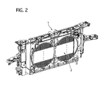
FIG. 2 is a rear perspective view showing the radiator core support, on which the condenser is mounted, of the embodiment according to the present invention; -
FIG. 3 is a front perspective view showing the radiator core support without the condenser; -
FIG. 4 is a rear perspective view showing the radiator core support without the condenser; -
FIG. 5 is a front perspective view showing the condenser; -
FIG. 6 is a rear perspective view showing the condenser; -
FIG. 7 is a schematic diagram illustrating respective flows of fluid medium flowing inside the condenser and a radiator; -
FIG. 8 is an enlarged perspective front view showing a range, indicated by a circle "A" inFIG. 5 , of the condenser; -
FIG. 9 is an enlarged perspective rear view showing a range, indicated by a circle "B" inFIG. 6 , of the condenser; -
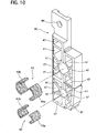
FIG. 10 is an exploded perspective view of a bracket; -
FIGS. 11A and 11B are views explaining how to fix a piping in the bracket, whereFIG. 11A is a view showing a state before the piping is fixed in the bracket, andFIG. 11B is a diagram showing a state where the piping is fixed in the bracket; -
FIG. 12 is a front perspective view illustrating a state where the bracket is mounted; and -
FIG. 13 is a rear perspective view explaining a state where the bracket is mounted. -
- D1, D2, D3, D4: partition plate
- O1, O2, O3: opening portion
- P: mounting pin
- PI: inlet port
- P2: outlet port
- R1, R2, R3, R4, R5, R6: chamber
- 1: radiator core support
- 2: integrated heat exchangers
- 3: radiator core support upper portion
- 4: radiator core support lower portion
- 4a: fixing hole
- 5: radiator core support side portion
- 6: shroud portion
- 7a, 7b: opening portion
- 8: through-hole
- 9: head lamp stay
- 10: condenser
- 11: radiator
- 12a, 12b: condenser tank
- 13, 20: condenser core part
- 14, 21: tube
- 15: fin
- 16, 17a, 17b: connecting pipe
- 17: receiver
- 18, 19: radiator tank
- 20: radiator core part
- 21a, 21b: reinforcement
- 22: screw hole
- 23: screw
- 30, 31: pipe
- 30a, 31a: vehicle-side connecting end portion
- 40: bracket
- 41, 42; through-hole
- 43: elastic member
- 43a, 43b: divided body portion
- 44a, 44b: hinge portion
- 45a, 45b: turning portion
- 46: fixing hole
- 47: draft depressions
- 48: projecting portion
- Hereinafter, an embodiment of the present invention will be described with reference to the accompanying drawings.
- Firstly, an entire construction of a radiator core support of the embodiment will be described.
The radiator core support of the embodiment is mounted on a front portion of a vehicle body of a motor vehicle, so that it forms a part of the vehicle body.
As shown inFIG. 1 andFIG. 2 ,integrated heat exchangers 2, consisting of a condenser and a radiator, are mounted on theradiator core support 1. - As shown in
FIG. 3 andFIG. 4 , theradiator core support 1 includes a radiator core supportupper portion 3 which extends in a lateral direction of the vehicle body, a radiator core supportlower portion 4 which is arranged parallel with theupper portion 3, right and left radiator coresupport side portions upper portion 3 andlower portion 4 with each other, and ashroud portion 6 which projects toward an inner side of the vehicle body from theupper portion 3, thelower portion 4, and theside portions radiator core support 1 is made of plastic material to be integrally formed. - In addition, in upper end portions of the right and left
side portions portions hole 8 is formed in the proximity of theopening portion 7a in a rectangular shape extending in a vertical direction of the motor vehicle.
Further, on intermediate portions of the right and leftside portions
Further, on left and right upper surfaces of thelower portion 4, left and right fixingholes
Incidentally, the whole of theradiator core support 1 may be made of metal instead of plastic material, or a part of thesupport 1 may be made of metal and the rest may be residually molded out of plastic material. - As shown in
FIG. 5 andFIG. 6 , thecondenser 10 and theradiator 11 constitute theintegrated heat exchanger 2 so that theradiator 11 is arranged at a rear side of thecondenser 10.
Thecondenser 10 has a pair of condenser tanks, namely afirst condenser tank 12a and asecond condenser tank 12b, and acondenser core part 13 which is arranged between the first andsecond condenser tanks
Thecondenser core part 13 has a plurality oftubes 14 and a plurality offins 15, where both end portions of thetubes 14 are inserted in and secured to their corresponding first andsecond condenser tanks fins 15 and thetubes 14 are alternately arranged to each other. - As shown in
FIG. 7 , an inner space of thefirst condenser tank 12a of thecondenser 10 is divided by a first partition plate D1 and a second partition plate D2 to form three chambers, namely a first chamber R1, a third chamber R3 and a sixth chamber R6, therein. In addition, as shown inFIG. 8 andFIG. 9 , afirst pipe 30 is provided so that it can be fluidically communicated with the first chamber R1 through aconnector 15, and similarly asecond pipe 31 is provided so that it can be fluidically communicated with the sixth chamber R6 through the connector 15a and a connectingpipe 16.
On the other hand, an inner space of thesecond condenser tank 12b is also divided by a third partition plate D3 and a fourth partition plate D4 to form three chambers, namely a second chamber R2, a fourth chamber R4 and a fifth chamber R5, therein. In addition, areceiver 17 is provided so that it can be fluidically communicated with the fourth and fifth chambers R4 and R5 through a first connectingpipe 17a and a second connectingpipe 17b, which are shown inFIG. 5 . - The
radiator 11 has a pair of radiator tanks, namely afirst radiator tank 18 and asecond radiator tank 19, and aradiator core part 20 which is arranged between the first andsecond radiator tanks
On an upper rear surface of thefirst radiator tank 18, an inlet port P1 is provided so that it can be fluidically communicated with an interior of thefirst radiator tank 18, while, on a lower rear surface of thesecond radiator tank 19, an outlet port P2 is provided so that it can be fluidically communicated with an interior of thesecond radiator tank 19.
Theradiator core part 20 has a plurality oftubes 21 and the plurality offins 15, where both end portions of thetubes 21 are inserted in and secured to their corresponding first andsecond radiator tanks fins 15 are used for both theradiator 11 and thecondenser 10, thetubes 21 and thefins 15 being arranged alternately to each other. Incidentally, thefins 15 do not need to be formed with both thecondenser 10 and theradiator 11, and they may be separated therefrom. - In the
integrated heat exchanger 2, a pair ofreinforcements second condenser tanks second radiator tanks condenser core part 13 and theradiator core part 20 are connected with each other to be reinforced.
On right, left, top and bottom portions of theintegrated heat exchangers 2, mounting pins P are provided, respectively, projecting vertically for mounting theheat exchangers 2 on theradiator core support 1. - As shown in
FIG. 8 andFIG. 9 , the first andsecond pipes bracket 40 at their portions in the vicinity of first and second vehicle-side connectingend portions 30a and 30b. - As shown in
FIG. 10 , thebracket 40 is made of a plastic plate to have dimensions enough to block off the through-hole 8 formed on theradiator core support 1. Thebracket 40 is formed at its substantially middle portion with a first through-hole 41 and a second through-hole 42, which are vertically apart from each other and are slightly larger in diameter than external diameters of their corresponding piping consisting of afirst pipe 30 and asecond pipe 31. The first and second through-holes elastic members 43, respectively. Each of the first and secondelastic members 43 consists of two dividedbody portions elastic body members 43 are made of rubber in the embodiment, they may use other elastic materials. In addition, theelastic members 43 are dispensable, the diameters of the first and second through-holes second pipes - As shown in
FIG. 11A , thebracket 40 has two turningportions walled hinge portions body portions bracket 40 can be attached to the first andsecond pipes end portions second pipes body portion 43b in an open state of the turningportions second pipes elastic members 43 with no gap therebetween. - In addition, the
bracket 40 is formed at its top portion with a fixinghole 46 having a circular shape, and it is also formed at its different positions with a plurality ofdraft depressions 47 with the aim of weight saving. Specifically, thebracket 40 is formed so that it has a plurality of ribs radially extending toward an outer circumferential frame portion of thebracket 40 from a supporting portion formed with the through-holes second pipes
Further, as shown inFIG. 9 , on rear sides and circumferences of the turningportions bracket 40, a plurality of projectingportions 48 are formed to extend outwardly. - Next, the operation of the
radiator core support 1 of the embodiment will be described.
In order to mount the thus constructedintegrated heat exchangers 2 on theradiator core support 1, firstly, theintegrated heat exchangers 2 attached with thebracket 40 are brought and inserted in an oblique direction from the front side of the motor vehicle, and then its vehicle-mounting pins P, which are provided on the right and left bottom portions of theintegrated heat exchangers 2, are inserted into the corresponding fixingholes 4a of the radiator core supportlower portion 4a through not-shown mounting rubbers. - Next, the
integrated heat exchangers 2 are rotated rearward to rise, and then, in this rising state, the vehicle-mounting pins P, which are provided on the right and left top portions of theintegrated heat exchanger 2, are secured to the radiator core supportupper portion 3 through not-shown mounting rubbers and brackets.
In this rising process, the first andsecond pipes hole 8, because the through-hole 8, through which the vehicle-side connectingend portions second pipes - Next, as shown in
FIG. 12 , thebracket 40 is secured to theradiator core support 1 by insertingscrews 23 into screw holes 22 of theradiator core support 1, as shown inFIG. 3 , through the fixinghole 46 of thebracket 40 and tightening thescrews 23. Incidentally, thebracket 40 may be secured by a clip, a bolt, of the like instead of using thescrew 23.
In this securing state of thebracket 40, gaps, which are formed between the through-hole 8 and thefirst pipe 30 and between the through-hole 8 and thesecond pipe 31, remain blocked off. In addition, as shown inFIG. 13 , the projectingportions 48, which are formed on the rear surface of thebracket 40, are contacted with the rim of the through-hole 8, thereby keeping the turningportions
Consequently, the vehicle-side connectingend portions second pipes bracket 40, in a state where they are elastically supported by thebracket 40 through theelastic members 43, respectively. - The thus constructed
radiator core support 1 is mounted on the motor vehicle, being provided with two not-shown motor fans which face theopenings - Then the vehicle-side connecting
end portions 30a and 30b of the first andsecond pipes condenser 10 are connected with connecting pipes of the vehicle-side devices, respectively, and the inlet and outlet ports P1 and P2 of theradiator 11 are connected with engine-side connecting pipes, respectively.
Specifically, the vehicle-side connectingend portion 30a of thefirst pipe 30 is connected with a connecting pipe of a not-shown compressor, and the vehicle-side connectingend portion 31 a of thesecond pipe 31 is connected with a connecting pipe of a not-shown evaporator.
In this connecting process, the vehicle-side connectingend portions pipes bracket 40 in the vicinities thereof. Therefore, this structure increases in stiffness, and accordingly they can be stably and easily connected with the vehicle-side connecting pipes without a bumpy movement in the connecting process. - As shown in
FIG. 7 , theradiator 11 functions in such a way that circulating medium X flows into thefirst radiator tank 18 from the engine side through the inlet port P1 at a temperature of approximately 110 °C, and then it is cooled down to a temperature of approximately 60 °C due to heat exchange through thefins 15 between the circulating medium X and air flow generated by vehicle running or by the fans while it flows through thetubes 21 of thecore part 20. Then the circulating medium X is discharged through the outlet port P2 to flow into thesecond radiator tank 19. - On the other hand, in the
condenser 10, circulating medium Y flows into the first chamber R1 of thefirst condenser tank 12a through thefirst pipe 30 and theconnector 15 from the compressor side at a temperature of approximately 70 °C, and then a heat-exchange occurs, through thefin 15, between the circulating medium Y and the air flow generated by the vehicle running or by the fans while the circulating medium flows through thetubes 14 which connect the first and second rooms R1 and R2 of the first andsecond tanks second condenser tank 12b. - The circulating medium Y that has entered the second room R2 flows through the
tubes 14, which connect the second room R2 and the third room R3, to enter the third room R3 of thefirst condenser tank 12a. Then the circulating medium Y in the third room R3 enters the fourth room R4 of thesecond condenser tank 12b through thetubes 14 which connect the third and fourth rooms R3 and R4 with each other, where it is cooled down due to the heat exchange between the circulating medium Y and the air flow generated by the vehicle running or by the fans while it flows therethrough. The circulating medium Y flows into the fourth room R4 of thesecond condenser tank 12b. - The circulating medium Y in the fourth room R4 is introduced through the first connecting
pipe 17a to thereceiver 17, where it is separated into gas and liquid, and then it enters the fifth room R5 through the second connectingpipe 17b. The circulating medium Y in the fifth room R5 is cooled down to a temperature of approximately 45 °C due to the heat exchange between the circulating medium Y and the air flow generated by the vehicle running or by the fans while it flows therethrough. The circulating medium Y flows into the sixth room R6 of thefirst condenser tank 12a.
Finally, the circulating medium Y in the sixth room R6 is discharged to the not-shown evaporator through the connectingpipe 16, theconnector 15, and thepipe 31, fulfilling the function of the condenser. - As described above, the gaps formed between the through-
holes 8 of theradiator core support 1 and thepipes integrated heat exchangers 2, which inhibits deterioration of the coolability thereof. - Further, the
integrated heat exchangers 2, including thecondenser 10, are softly mounted on theradiator core support 1. In the embodiment, since thepipes bracket 40 through theelastic members 43, respectively, vibrations of thepipes - Further, this structure prevents the
bracket 40 and thepipes bracket 40 from being cracked and/or destroyed. - Next, the advantages of the radiator core support of the embodiment will be described.
As described above, in a pipe supporting structure of thecondenser 10 according to the embodiment, the radiator core support is constructed in such a way that thecondenser 10 is mounted on the front side of theradiator core support 1 and the vehicle-side connectingend portions pipes condenser 10 are laid so that they pass through the through-hole 8 formed on the radiator core support in the state where they project rearward. It is provided with thebracket 40 which is capable of supporting thepipes pipes hole 8 are blocked off. This enables the vehicle-side connectingend portions pipes condenser 10 to be easily connected with the vehicle side device, preventing the hot air from blowing back from the engine side to the front side of thecondenser 10 through the gaps formed between thepipes hole 8. - In addition, the
pipes bracket 40, - The invention is not limited to the embodiment described above. Design changes and modifications are considered to be within the invention as long as they are within the spirit and the scope of the invention.
For example, thebracket 40 and theelastic member 43 are appropriately determined in their material and configurations of specific portions.
In addition, in theintegrated heat exchangers 2 of the described embodiment, thecondenser 10 is integrally formed with theradiator 11, while they may be arranged in such a way that they are constructed to be separated from each other.
Further, in the described embodiment, thepipes condenser 10 are laid in a state where they pass through the through-hole 8 in the embodiment, while thepipes - The invention is suitable for providing a radiator core support in which a pipe of a condenser passes therethrough.
Claims (4)
- A radiator core support in which a condenser is arranged on a front side of the radiator core support and in which a vehicle side connecting end portion of a piping of the condenser passes through a through-hole formed on the radiator core support in a state where the end portion is projected rearward therethrough, the radiator core support being characterized in that it is provided with a bracket which is capable of holding the piping in a state where the bracket blocks off a gap formed between the piping and the through-hole.
- The radiator core support according to claim 1, wherein
the bracket is elastically supported by the piping. - The radiator core support according to claim 1 or claim 2, wherein
the piping has two pipes, and wherein
the bracket is formed so that an upper portion of the bracket is turnable around an upper end portion thereof so as to open for allowing one pipe of the piping to be inserted from a lower side, and so that a lower portion of the bracket is turnable around a lower end portion thereof so as to open for allowing the other pipe of the piping to be inserted from an upper side. - The radiator core support according to any one of claims 1 to 3, wherein the bracket has a plurality of ribs which extend radially from a supporting portion forming the through-hole, through which the piping passes, to an outer circumferential frame portion of the bracket.
Applications Claiming Priority (2)
| Application Number | Priority Date | Filing Date | Title |
|---|---|---|---|
| JP2005320893A JP4907152B2 (en) | 2005-11-04 | 2005-11-04 | Radiator core support |
| PCT/JP2006/321609 WO2007052577A1 (en) | 2005-11-04 | 2006-10-30 | Radiator core support |
Publications (2)
| Publication Number | Publication Date |
|---|---|
| EP1950073A1 true EP1950073A1 (en) | 2008-07-30 |
| EP1950073A4 EP1950073A4 (en) | 2009-11-11 |
Family
ID=38005729
Family Applications (1)
| Application Number | Title | Priority Date | Filing Date |
|---|---|---|---|
| EP06822566A Withdrawn EP1950073A4 (en) | 2005-11-04 | 2006-10-30 | Radiator core support |
Country Status (6)
| Country | Link |
|---|---|
| US (1) | US20100044007A1 (en) |
| EP (1) | EP1950073A4 (en) |
| JP (1) | JP4907152B2 (en) |
| KR (1) | KR20080073701A (en) |
| CN (1) | CN101300149A (en) |
| WO (1) | WO2007052577A1 (en) |
Cited By (1)
| Publication number | Priority date | Publication date | Assignee | Title |
|---|---|---|---|---|
| FR2941518A1 (en) * | 2009-01-26 | 2010-07-30 | Valeo Systemes Thermiques | Heating, ventilation and/or air-conditioning installation for use in motor vehicle, has connector placed in housing, and assembly device with limit unit to limit displacement of connector in rotation inside housing |
Families Citing this family (9)
| Publication number | Priority date | Publication date | Assignee | Title |
|---|---|---|---|---|
| DE102005039090A1 (en) * | 2005-08-06 | 2007-02-08 | Behr Gmbh & Co. Kg | Assembly support system |
| JP5078825B2 (en) | 2008-03-26 | 2012-11-21 | カルソニックカンセイ株式会社 | Radiator core support |
| JP2011232006A (en) * | 2010-04-30 | 2011-11-17 | Calsonic Kansei Corp | Supporting member of heat exchanger |
| DE102012214783A1 (en) * | 2012-08-20 | 2014-02-20 | Behr Gmbh & Co. Kg | Heat exchanger for a battery unit |
| FR2997917B1 (en) * | 2012-11-13 | 2016-04-15 | Renault Sa | "MOTOR VEHICLE WITH REAR ENGINE COMPRISING AN OPTIMIZED FRONT COMPARTMENT" |
| JP6106459B2 (en) * | 2013-02-26 | 2017-03-29 | 株式会社ケーヒン | Air conditioner for vehicles |
| WO2015004821A1 (en) * | 2013-07-11 | 2015-01-15 | Smc株式会社 | Constant-temperature-fluid circulation device |
| CN104085291A (en) * | 2014-07-22 | 2014-10-08 | 马勒贝洱热系统(济南)有限公司 | Vehicle cooling module and installation connection structure thereof |
| FR3028605B1 (en) * | 2014-11-14 | 2019-04-05 | Valeo Systemes Thermiques | FIXING DEVICE FOR HEAT EXCHANGER |
Family Cites Families (12)
| Publication number | Priority date | Publication date | Assignee | Title |
|---|---|---|---|---|
| JPH01145811A (en) * | 1987-12-01 | 1989-06-07 | Hitachi Ltd | Alignment and apparatus therefor |
| DE19731999A1 (en) * | 1997-07-25 | 1999-02-04 | Laengerer & Reich Gmbh & Co | Cooling module |
| GB9805379D0 (en) * | 1998-03-14 | 1998-05-06 | Grayson Automotive Services Li | Heat exchanger assemblies for vehicles |
| JP2000018874A (en) | 1998-06-24 | 2000-01-18 | Nippon Light Metal Co Ltd | Heat exchanger |
| JP2002061988A (en) * | 2000-08-15 | 2002-02-28 | Calsonic Kansei Corp | Refrigerant transferring connector |
| KR100369016B1 (en) * | 2000-12-19 | 2003-01-24 | 현대자동차주식회사 | Structure for sealing a heater unit of an automobile |
| US6513579B1 (en) * | 2001-09-27 | 2003-02-04 | Delphi Technologies, Inc. | Post braze heat exchanger mounting and support brackets |
| DE10306905C5 (en) * | 2003-02-18 | 2012-05-24 | Itw Automotive Products Gmbh & Co. Kg | retaining element |
| JP2005053444A (en) * | 2003-08-07 | 2005-03-03 | Calsonic Kansei Corp | Piping structure of condenser of parallel type heat-exchanger for vehicle |
| JP2005147186A (en) * | 2003-11-12 | 2005-06-09 | Nippon Pop Rivets & Fasteners Ltd | Holder |
| JP2005161979A (en) * | 2003-12-02 | 2005-06-23 | Calsonic Kansei Corp | Front structure of automobile body |
| JP5078825B2 (en) * | 2008-03-26 | 2012-11-21 | カルソニックカンセイ株式会社 | Radiator core support |
-
2005
- 2005-11-04 JP JP2005320893A patent/JP4907152B2/en not_active Expired - Fee Related
-
2006
- 2006-10-30 EP EP06822566A patent/EP1950073A4/en not_active Withdrawn
- 2006-10-30 KR KR1020087009677A patent/KR20080073701A/en not_active Withdrawn
- 2006-10-30 US US12/083,335 patent/US20100044007A1/en not_active Abandoned
- 2006-10-30 WO PCT/JP2006/321609 patent/WO2007052577A1/en not_active Ceased
- 2006-10-30 CN CNA2006800412293A patent/CN101300149A/en active Pending
Cited By (1)
| Publication number | Priority date | Publication date | Assignee | Title |
|---|---|---|---|---|
| FR2941518A1 (en) * | 2009-01-26 | 2010-07-30 | Valeo Systemes Thermiques | Heating, ventilation and/or air-conditioning installation for use in motor vehicle, has connector placed in housing, and assembly device with limit unit to limit displacement of connector in rotation inside housing |
Also Published As
| Publication number | Publication date |
|---|---|
| WO2007052577A1 (en) | 2007-05-10 |
| US20100044007A1 (en) | 2010-02-25 |
| KR20080073701A (en) | 2008-08-11 |
| EP1950073A4 (en) | 2009-11-11 |
| JP2007126020A (en) | 2007-05-24 |
| JP4907152B2 (en) | 2012-03-28 |
| CN101300149A (en) | 2008-11-05 |
Similar Documents
| Publication | Publication Date | Title |
|---|---|---|
| US7640966B2 (en) | Heat exchanger and cooling module having the same | |
| JP3191385B2 (en) | Condenser mounting device | |
| CN100439135C (en) | Vehicle air conditioner | |
| EP1950073A1 (en) | Radiator core support | |
| US20070181105A1 (en) | Heat exchanger and method of connecting | |
| JPH0930246A (en) | Vehicle heat exchange device | |
| US20070051488A1 (en) | Heat exchanger for motor vehicle | |
| CN219769584U (en) | Thermal management module and connection bracket | |
| JP7446561B2 (en) | vehicle radiator | |
| JP4319887B2 (en) | Heat exchanger | |
| JP3799782B2 (en) | Vehicle heat exchanger device | |
| JP4155830B2 (en) | Mounting structure of liquid receiver | |
| JP5106326B2 (en) | Air conditioner for vehicles | |
| JP4420689B2 (en) | Automobile front structure | |
| JP2005206054A (en) | Heat exchanger for vehicle | |
| CN220087754U (en) | Assembled heat pipe heat abstractor | |
| JP5860666B2 (en) | Air conditioner for vehicles | |
| KR101173312B1 (en) | Cover Structure of Heater Core Pipe for an Air Conditioning System of a Car | |
| JP2007271149A (en) | Refrigerant condenser mounting structure | |
| JP4371876B2 (en) | Air conditioner for vehicles | |
| JP2007276732A (en) | Air conditioner for vehicles | |
| JP2006347206A (en) | Mounting structure of heat exchanger | |
| US20170356699A1 (en) | Attachment device for heat exchanger | |
| KR100391539B1 (en) | Heat exchanger capable of integrated radiator and condenser | |
| KR200352274Y1 (en) | Assembly Structure of Radiator and Fan Shroud |
Legal Events
| Date | Code | Title | Description |
|---|---|---|---|
| PUAI | Public reference made under article 153(3) epc to a published international application that has entered the european phase |
Free format text: ORIGINAL CODE: 0009012 |
|
| 17P | Request for examination filed |
Effective date: 20080603 |
|
| AK | Designated contracting states |
Kind code of ref document: A1 Designated state(s): DE FR GB |
|
| DAX | Request for extension of the european patent (deleted) | ||
| RBV | Designated contracting states (corrected) |
Designated state(s): DE FR GB |
|
| RA4 | Supplementary search report drawn up and despatched (corrected) |
Effective date: 20090914 |
|
| A4 | Supplementary search report drawn up and despatched |
Effective date: 20090914 |
|
| STAA | Information on the status of an ep patent application or granted ep patent |
Free format text: STATUS: THE APPLICATION IS DEEMED TO BE WITHDRAWN |
|
| 18D | Application deemed to be withdrawn |
Effective date: 20091212 |