EP1949779B1 - Dispositif et procede de retournement de composants electroniques - Google Patents
Dispositif et procede de retournement de composants electroniques Download PDFInfo
- Publication number
- EP1949779B1 EP1949779B1 EP06819183A EP06819183A EP1949779B1 EP 1949779 B1 EP1949779 B1 EP 1949779B1 EP 06819183 A EP06819183 A EP 06819183A EP 06819183 A EP06819183 A EP 06819183A EP 1949779 B1 EP1949779 B1 EP 1949779B1
- Authority
- EP
- European Patent Office
- Prior art keywords
- over
- turning
- location
- turntable
- component
- Prior art date
- Legal status (The legal status is an assumption and is not a legal conclusion. Google has not performed a legal analysis and makes no representation as to the accuracy of the status listed.)
- Not-in-force
Links
Images

Classifications
-
- H—ELECTRICITY
- H05—ELECTRIC TECHNIQUES NOT OTHERWISE PROVIDED FOR
- H05K—PRINTED CIRCUITS; CASINGS OR CONSTRUCTIONAL DETAILS OF ELECTRIC APPARATUS; MANUFACTURE OF ASSEMBLAGES OF ELECTRICAL COMPONENTS
- H05K13/00—Apparatus or processes specially adapted for manufacturing or adjusting assemblages of electric components
- H05K13/04—Mounting of components, e.g. of leadless components
-
- H—ELECTRICITY
- H10—SEMICONDUCTOR DEVICES; ELECTRIC SOLID-STATE DEVICES NOT OTHERWISE PROVIDED FOR
- H10P—GENERIC PROCESSES OR APPARATUS FOR THE MANUFACTURE OR TREATMENT OF DEVICES COVERED BY CLASS H10
- H10P72/00—Handling or holding of wafers, substrates or devices during manufacture or treatment thereof
- H10P72/30—Handling or holding of wafers, substrates or devices during manufacture or treatment thereof for conveying, e.g. between different workstations
- H10P72/32—Handling or holding of wafers, substrates or devices during manufacture or treatment thereof for conveying, e.g. between different workstations between different workstations
- H10P72/3211—Changing orientation of the substrate, e.g. from a horizontal position to a vertical position
-
- H—ELECTRICITY
- H05—ELECTRIC TECHNIQUES NOT OTHERWISE PROVIDED FOR
- H05K—PRINTED CIRCUITS; CASINGS OR CONSTRUCTIONAL DETAILS OF ELECTRIC APPARATUS; MANUFACTURE OF ASSEMBLAGES OF ELECTRICAL COMPONENTS
- H05K13/00—Apparatus or processes specially adapted for manufacturing or adjusting assemblages of electric components
- H05K13/02—Feeding of components
-
- H—ELECTRICITY
- H10—SEMICONDUCTOR DEVICES; ELECTRIC SOLID-STATE DEVICES NOT OTHERWISE PROVIDED FOR
- H10P—GENERIC PROCESSES OR APPARATUS FOR THE MANUFACTURE OR TREATMENT OF DEVICES COVERED BY CLASS H10
- H10P72/00—Handling or holding of wafers, substrates or devices during manufacture or treatment thereof
- H10P72/30—Handling or holding of wafers, substrates or devices during manufacture or treatment thereof for conveying, e.g. between different workstations
- H10P72/32—Handling or holding of wafers, substrates or devices during manufacture or treatment thereof for conveying, e.g. between different workstations between different workstations
- H10P72/3212—Handling or holding of wafers, substrates or devices during manufacture or treatment thereof for conveying, e.g. between different workstations between different workstations the substrates to be conveyed not being semiconductor wafers or large planar substrates, e.g. chips or lead frames
-
- Y—GENERAL TAGGING OF NEW TECHNOLOGICAL DEVELOPMENTS; GENERAL TAGGING OF CROSS-SECTIONAL TECHNOLOGIES SPANNING OVER SEVERAL SECTIONS OF THE IPC; TECHNICAL SUBJECTS COVERED BY FORMER USPC CROSS-REFERENCE ART COLLECTIONS [XRACs] AND DIGESTS
- Y10—TECHNICAL SUBJECTS COVERED BY FORMER USPC
- Y10T—TECHNICAL SUBJECTS COVERED BY FORMER US CLASSIFICATION
- Y10T29/00—Metal working
- Y10T29/53—Means to assemble or disassemble
- Y10T29/5313—Means to assemble electrical device
- Y10T29/53174—Means to fasten electrical component to wiring board, base, or substrate
- Y10T29/53178—Chip component
Definitions
- the present invention relates to a device for turning over electronic components.
- the electronic components During their manufacture or testing, the electronic components successively browse different processing locations.
- the locations are often evenly spaced on the periphery of a cylinder whose indexed rotation allows to move the components from one location to another.
- Each of these locations is usually occupied by a processing station performing one or more operations on the electronic components presented to it.
- a treatment station may occupy multiple locations.
- the set of treatment stations arranged around the barrel thus forms a cycle of successive operations, for example electrical or mechanical tests, packaging operations, etc., to which the electronic components conveyed on the barrel are subjected.
- Known barrels for example 16 or 32 locations.
- the first cycle processing station is generally an entry station whose role is essentially to bring the electronic components from a tank or from another conveyor on the barrel.
- the cycle may comprise one or more output stations, thus enabling the components to be released at different stages of the cycle, for example as a function of characteristics measured on a previous test station.
- the patent application WO2004 / 023858 in the name of the Applicant describes an advantageous turning device because it occupies a single processing station.
- the flipping of the components is however caused by a linear actuator, for example a pneumatic cylinder.
- a linear actuator for example a pneumatic cylinder.
- the actuator acts on a rod whose vertical back and forth cause the passage and the flipping of the components of a component holder to another.
- the axis of this rod is however confused with the axis of rotation of the component holder.
- the motor driving the rotational component holders must therefore be placed off-axis; in this solution, it is connected by a belt to the turning mechanism.
- US B1-6,468,023 describes a turning mechanism which uses an arm in rotation about a horizontal axis.
- the arm goes back and forth between a start-up location and an end-of-turn location.
- the motor actuating the arm must therefore change direction of rotation twice each cycle, so that it is difficult to obtain very high speeds.
- the rotating mass with the arm is very important.
- the position of the returned component is not fully controlled.
- An object of the present invention is therefore to provide an electronic device reversal device improved over the devices of the prior art.
- Another object is to provide a turning device adapted to return electronic components between two successive processing stations of a conveyor or a rotary drum.
- This solution has the advantage of using only rotary motors, which can also be rotated in one direction throughout a reversal cycle.
- the motor driving the turntable always rotates in the same direction while the fixed rotary motor actuating the turning device carries out back and forth movements.
- This solution also has the advantage of separating the turning motor from the turntable, and to avoid a space around the axis of rotation of the plate.
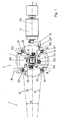
- the reversal device of the invention is represented on the figures 1 and 2 ; only the components necessary for understanding the reversal process have been illustrated.
- the turning device is intended to cooperate with a conveyor which brings a succession of components in a first position, for example with the tabs at the bottom, and resumes in the inverted position, for example with the tabs at the top.
- the conveyor is constituted by a rotary barrel 3 with vertical axis of which only an angular portion of the periphery 30 is shown schematically.
- the barrel comprises for example 16 or 32 peripheral locations on which are arranged treatment stations.
- the rotational movements of the barrel are preferably indexed; the components to be treated pass from one location to another at each step and thus successively browse these different processing stations to be tested, marked, packaged, etc.
- the reversal device of the invention occupies two successive locations of the barrel 3.
- the electronic components to be returned are removed from the barrel at a first location and placed on a first location A of the turntable 1 of the turning device.
- the turntable 1 is horizontal; it is rotated in an indexed manner by the electric motor 4 (for example a DC motor or a stepper motor) so as to traverse the four successive locations ABCD.
- the component is returned between locations B and C and discharged from turntable 1 to location D, where it joins a second location of the barrel 3.
- the reference 31 on the figure 1 indicates the radius of the first location of the barrel, from which are extracted the electronic compounds loaded on the turntable.
- the reference 32 corresponds to the radius of the second location where the components returned from the last location D of the turntable are positioned.
- the component to be returned is placed on the component holder 20 at the location A from the barrel 3 by means of placement not shown.
- the placement means as well as the shape of the component holder collaborate so that the position of the component on the component holder is accurately determined, and reproducibly from one component to another.
- the component holder 20 is provided with a nozzle 201, connected to a not shown pneumatic channel, which makes it possible to suck or blow air in order to keep the component in place or, on the contrary, to push it back.
- the pneumatic circuit also makes it possible to generate a stable "neutral point" in which the component is neither pushed nor sucked; a command makes it possible to pass it directly to this neutral point.
- the pneumatic channel preferably comprises a circular path, not shown, allowing the nozzle to remain connected to the channel during its rotations.
- the component door 20 is articulated around the axis of turning parallel to the horizontal plate 200.
- a spring 203 visible on the figure 2 , maintains the component holder 20 in the substantially horizontal position illustrated on the figures 1 and 2 .
- the spring 203 is stretched between the axis 20X, integral with the part 20, and the axis 20Y integral with the frame.
- the component holder 20 may preferably pivot at least 180 ° about the axis 200 so as to return the component relative to a horizontal plane while moving it.
- the axis 200 is positioned above the plane of the component holder on which is placed the component to be returned, in the middle of the thickness of the component, so as to allow the reversal of a component door to the location B by above another component holder at the location C, the nozzles of the two component holders then being aligned around the same vertical axis.
- a dimension of the component at the location B is aligned with the radius 31 which leads to the center of the barrel 3 through the first location of the barrel.
- the axis of rotation 200 of the component holder at the location B is however parallel to the axis of symmetry 33 between two successive locations of the barrel.
- the overturning of the component holder to the location B is actuated by the turning motor 21, for example a DC rotary motor or a stepper motor.
- the axis 210 of rotation of the motor 21 is horizontal and in the same plane as the turning axis 200. In the preferred embodiment illustrated, the axis 210 and the axis 200 are even coincident.
- the motor drives an eccentric part 22 whose end is provided with a slot 220 which makes it possible to receive a horizontal rod 202 connected to the component holder at the location B.
- a kinematic connection between the motor 21 and the component holder 20 therefore exists only when the latter is in the location B.
- the eccentric part 22 is thus arranged to mesh only with the rod 202 associated with the component holder at the location B.
- Rotation of the motor drives the rod 202 in a direction having a vertical component, thereby lifting the component holder against the force of the spring 203 and returning it about the axis 200, until it is superimposed on the component holder at location C.
- the component can then be deposited on the component holder at location C by controlling the pneumatic pressure on the nozzles 201 appropriately, as described below.
- the cycle traveled by one by one component between locations A and D of the turntable leaves the barrel 3 and is placed on the slot A of the component holder.
- the pneumatic circuit is controlled to hold the component in place by sucking air through the nozzle 201 at that location.
- Other means for holding the component may be used in the context of the invention, including mechanical gripping means.
- the motor 4 then rotates the turntable 1 with the four component holders 90 ° counter-clockwise, so that the component is now found at the start position of reversal B.
- the precise amplitude of the rotation is preferably controlled by means of an angular encoder providing a feedback signal to a control electronics of the motor 4.
- the rod 202 associated with the component holder is housed in the slot 220 of the eccentric part 22.
- the reversal is then effected by means of the motor 21 which actuates the eccentric part 22 so as to lift the component holder 20 to the location B and to rotate it 180 ° about the axis 200.
- the amplitude of the rotation of the motor 21 is controlled by means of a second angular encoder acting on the control current of the motor 21, or by means of end-of-travel detectors.
- the air gap under the nozzle 201 is maintained during inversion, so as to hold the component in place.
- the nozzle 201 of the component holder at the location C is actuated by the pneumatic system so as to create a slight vacuum of air, or a neutral pressure.
- the pneumatic system is controlled so as to interrupt the suction of air through the nozzle connected to the returned component holder B, and to create or increase the air gap of the nozzle connected to the component holder C. It is even possible to create a slight overpressure in the pneumatic circuit connected to the component holder B, so as to repel the component. The component is thus detached from the component holder B, and attracted by the component holder C, its position being accurately controlled.
- the component holder B then returns to its initial location B.
- it is returned to its initial location by means of the motor 21 which goes back and forth to replace the component holder in its position B.
- This variant has however the disadvantage of requiring a bidirectional motor 21, and require inversions of its direction of rotation, which slows the process.
- the spring 203 is used to return the component holder to its initial position.
- the rotary plate 1 resumes its rotation in the counterclockwise direction, until the rod 201 is disengaged from the slot 220 of the eccentric part.
- the spring 203 then exerts a restoring force to return the component holder to its initial position B.
- the cycle continues with rotation of the turntable by 90 ° in the counterclockwise cycle.
- the component thus passes from the location C to the location D, where it can be discharged from the turntable 1 and transferred in the inverted position on the conveyor.
- the turntable 1 has 4 locations for components 1. It is of course possible to start a new turnaround cycle of the next component before the first component has left the tray.
- a new component is loaded on slot A with each rotation of the tray, and a returned component is simultaneously discharged from slot D.
- no position of the barrel remains empty: at each step, a component is unloaded on slot A, and another returned component is loaded from slot D.
- the reversing device of the invention comprises four successive locations A, B, C and D.
- the component to be returned could be loaded directly to the start of rollover position, or directly unloaded from the end of rollover position, in order to reduce the number of locations.
- intermediate locations for intermittent storage or to perform additional operations for example additional turning operations along the same axis 200 or other orthogonal axis, for example.
- marking operations, testing, sorting, for example could also be performed on these intermediate locations.
- all the movements of the barrel, the engines 4 and 21, as well as the air pressures in the various chambers of the circuit pneumatic are preferably controlled by a control system not shown, for example a CNC-type programmable digital system.
- the control system can be programmed by a program that can be marketed or updated through appropriate computer data carriers.
- the turning device is associated with a circular barrel.
- the turning device is associated with another type of conveyor, for example a linear conveyor.
Landscapes
- Engineering & Computer Science (AREA)
- Manufacturing & Machinery (AREA)
- Microelectronics & Electronic Packaging (AREA)
- Specific Conveyance Elements (AREA)
Description
- La présente invention concerne un dispositif de retournement de composants électroniques.
- Au cours de leur fabrication ou de leur test, les composants électroniques parcourent successivement différents emplacements de traitement. Les emplacements sont souvent régulièrement espacés sur la périphérie d'un barillet dont la rotation indexée permet de déplacer les composants d'un emplacement à l'autre.
- Chacun de ces emplacements est généralement occupé par un poste de traitement effectuant une ou plusieurs opérations sur les composants électroniques qui lui sont présentés. Dans certains cas, un poste de traitement peut occuper plusieurs emplacements. L'ensemble des postes de traitement disposés autour du barillet forme ainsi un cycle d'opérations successives, par exemple de tests électriques ou mécaniques, d'opérations de conditionnement, etc., auquel les composants électroniques convoyés sur le barillet sont soumis. On connaît par exemple des barillets à 16 ou à 32 emplacements.
- Le premier poste de traitement du cycle est généralement un poste d'entrée dont le rôle consiste essentiellement à amener les composants électroniques, depuis un réservoir ou depuis un autre convoyeur, sur le barillet. Le cycle peut comprendre un ou plusieurs postes de sortie, permettant ainsi de sortir les composants à différentes étapes du cycle, par exemple en fonction de caractéristiques mesurées sur un précédent poste de test.
- Il arrive souvent que deux postes de traitement successifs doivent accéder à des faces opposées des composants électroniques. Par exemple, un poste de marquage doit pouvoir accéder à la face supérieure du composant à marquer alors que le test électrique de circuit intégré est souvent effectué en position retournée, dite « dead bug ». Il est donc nécessaire de retourner les composants électroniques entre les deux postes de traitement.
- La demande de brevet
WO2004/023858 au nom de la demanderesse décrit un dispositif de retournement avantageux parce qu'il occupe un seul poste de traitement. Le retournement des composants est toutefois provoqué par un actionneur linéaire, par exemple un vérin pneumatique. Un tel vérin est généralement plus lent et plus difficile à contrôler qu'un moteur électrique rotatif. L'actionneur agit sur une tige dont les va-et-vient verticaux provoquent le passage et le retournement des composants d'un porte-composant à un autre. L'axe de cette tige se confond cependant avec l'axe de rotation des porte-composants. Le moteur entraînant les porte-composants en rotation doit donc être placé de manière désaxée ; dans cette solution, il est relié par une courroie au mécanisme de retournement. Il est cependant difficile de transmettre des mouvements extrêmement rapides avec une précision très élevée au moyen de courroies. Par ailleurs, le composant retourné revenant sur son emplacement initial, il est nécessaire d'effectuer les opérations de retournement en temps masqué du convoyeur, ce qui est uniquement possible si la vitesse du dispositif de retournement est nettement plus importante que la vitesse du convoyeur. Cette solution est donc idéale essentiellement lorsque l'exigence d'occuper un seul emplacement autour du barillet est impérative. - D'autres solutions existent qui font appel à un bras à l'extrémité duquel se trouve un élément de préhension destiné à saisir le composant électronique et à le maintenir pendant que le bras tourne de 180° pour retourner le composant. La réalisation de cet élément de préhension, en regard d'une face latérale du composant, est cependant délicate.
-
US-B1-6,468,023 décrit un mécanisme de retournement qui fait appel à un bras en rotation autour d'un axe horizontal. Le bras fait des allers-retours entre un emplacement de début de retournement et un emplacement de fin de retournement. Le moteur actionnant le bras doit donc changer de sens de rotation deux fois à chaque cycle, en sorte qu'il est difficile d'obtenir des vitesses très élevées. D'autre part, la masse en rotation avec le bras est très importante. En outre, la position du composant retourné n'est pas entièrement contrôlée. - Un but de la présente invention est donc de proposer un dispositif de retournement de composants électroniques amélioré par rapport aux dispositifs de l'art antérieur.
- Un autre but est de proposer un dispositif de retournement apte à retourner des composants électroniques entre deux postes de traitement successifs d'un convoyeur ou d'un barillet rotatif.
- Selon l'invention, ces buts sont atteints au moyen d'un dispositif de retournement de composants électroniques comportant :
- un plateau rotatif pour entraîner les composants électroniques à retourner successivement entre les emplacements fixes suivants: un emplacement de chargement sur le plateau, un emplacement de début de retournement, un emplacement de fin de retournement, et un emplacement de déchargement du plateau,
- un dispositif de retournement actionné par un moteur rotatif fixe, non lié audit plateau, pour retourner lesdits composants électroniques entre ladite position de début de retournement et la position de fin de retournement.
- Cette solution a l'avantage d'employer uniquement des moteurs rotatifs, qu'il est en outre possible de faire tourner dans un seul sens tout au long d'un cycle de retournement. Dans une variante, le moteur entraînant le plateau rotatif tourne toujours dans le même sens tandis que le moteur rotatif fixe actionnant le dispositif de retournement effectue des al lers-retours.
- Cette solution a aussi l'avantage de séparer le moteur de retournement du plateau rotatif, et d'éviter un encombrement autour de l'axe de rotation du plateau.
- L'invention sera mieux comprise à la lecture de la description annexée illustrée par les figures qui montrent :
- La
figure 1 une vue partielle du dispositif de retournement depuis dessus. - La
figure 2 une vue latérale partielle du dispositif de retournement. - Le dispositif de retournement de l'invention est représenté sur les
figures 1 et2 ; seuls les composants nécessaires à la compréhension du procédé de retournement ont été illustrés. Le dispositif de retournement est destiné à coopérer avec un convoyeur qui apporte une succession de composants dans une première position, par exemple avec les pattes en bas, et les reprend en position retournée, par exemple avec les pattes en haut. Dans cet exemple préférentiel, le convoyeur est constitué par un barillet rotatif 3 à axe vertical dont seule une portion angulaire de la périphérie 30 est représentée de manière schématique. Le barillet comporte par exemple 16 ou 32 emplacements périphériques sur lesquels sont disposés des postes de traitement. Les mouvements de rotation du barillet sont de préférence indexés ; les composants à traiter passent d'un emplacement à l'autre à chaque pas et parcourent ainsi successivement ces différents postes de traitement pour être testés, marqués, conditionnés, etc. - Le dispositif de retournement de l'invention occupe deux emplacements successifs du barillet 3. Les composants électroniques à retourner sont extraits du barillet en un premier emplacement et placés sur un premier emplacement A du plateau rotatif 1 du dispositif de retournement. Dans ce mode de réalisation, le plateau rotatif 1 est horizontal ; il est entraîné en rotation de manière indexée par le moteur électrique 4 (par exemple un moteur à courant continu ou un moteur pas-à-pas), de manière à parcourir les quatre emplacements successifs A-B-C-D. Le composant est retourné entre les emplacements B et C et déchargé du plateau rotatif 1 à l'emplacement D, où il rejoint un deuxième emplacement du barillet 3. La référence 31 sur la
figure 1 indique le rayon du premier emplacement du barillet, d'où sont extraits les composés électroniques chargés sur le plateau rotatif. La référence 32 correspond au rayon du deuxième emplacement où sont positionnés les composants retournés depuis le dernier emplacement D du plateau rotatif. - Le composant à retourner est placé sur le porte-composant 20 à l'emplacement A à partir du barillet 3 grâce à des moyens de placement non représentés. Les moyens de placement ainsi que la forme du porte-composant collaborent afin que la position du composant sur le porte-composant soit déterminée avec précision, et de manière reproductible d'un composant à l'autre. Le porte-composant 20 est muni d'une buse 201, reliée à un canal pneumatique non représenté, qui permet d'aspirer ou de souffler de l'air afin de maintenir le composant en place ou au contraire de le repousser. Dans une variante, le circuit pneumatique permet aussi de générer un « point neutre » stable dans lequel le composant n'est ni repoussé, ni aspiré ; une commande permet de le faire passer directement à ce point neutre. Le canal pneumatique comporte de préférence un chemin circulaire, non représenté, permettant à la buse de rester connectée au canal lors de ses rotations.
- Le porte composant 20 est articulé autour de l'axe de retournement parallèle au plateau horizontal 200. Un ressort 203, visible sur la
figure 2 , maintient le porte-composant 20 dans la position sensiblement horizontale illustrée sur lesfigures 1 et2 . Le ressort 203 est tendu entre l'axe 20X, solidaire de la pièce 20, et l'axe 20Y solidaire du châssis. Le porte-composant 20 peut de préférence pivoter de 180° au moins autour de l'axe 200, de manière à retourner le composant par rapport à un plan horizontal tout en le déplaçant. L'axe 200 est positionné au-dessus du plan du porte-composant sur lequel est placé le composant à retourner, au milieu de l'épaisseur du composant, de manière à permettre le retournement d'un porte composant à l'emplacement B par-dessus un autre porte-composant à l'emplacement C, les buses des deux porte-composants étant alors alignées autour d'un même axe vertical. - Une dimension du composant à l'emplacement B est alignée par rapport au rayon 31 qui mène au centre du barillet 3 en passant par le premier emplacement du barillet. L'axe de rotation 200 du porte-composant à l'emplacement B est en revanche parallèle à l'axe de symétrie 33 entre deux emplacements successifs du barillet. En retournant le composant autour de l'axe 200, on aligne ainsi sa dimension par rapport au rayon 32 passant par le deuxième emplacement. Le déplacement du composant entre la position B et la position C est donc une combinaison entre un retournement autour d'un axe horizontal et une rotation d'angle α autour de l'axe vertical passant par le centre du barillet 3.
- Le retournement du porte-composant à l'emplacement B est actionné par le moteur de retournement 21, par exemple un moteur rotatif à courant continu ou un moteur pas-à-pas. L'axe 210 de rotation du moteur 21 est horizontal et dans le même plan que l'axe de retournement 200. Dans la variante préférentielle illustrée, l'axe 210 et l'axe 200 sont même confondus. Le moteur entraîne une pièce excentrique 22 dont l'extrémité est munie d'une fente 220 qui permet de recevoir une tige 202 horizontale liée au porte-composant à l'emplacement B. Une liaison cinématique entre le moteur 21 et le porte-composant 20 existe donc uniquement lorsque que ce dernier se trouve à l'emplacement B. La pièce excentrique 22 est ainsi agencée pour engrener uniquement avec la tige 202 associée au porte-composant à l'emplacement B.
- La rotation du moteur entraîne la tige 202 dans une direction comportant une composante verticale, soulevant ainsi le porte-composant à l'encontre de la force du ressort 203 et le retournant autour de l'axe 200, jusqu'à ce qu'il soit superposé au porte-composant à l'emplacement C. Le composant peut alors être déposé sur le porte-composant à l'emplacement C en contrôlant la pression pneumatique sur les buses 201 de façon appropriée, comme décrit plus bas.
- Nous allons maintenant décrire le cycle parcouru par un par un composant entre les emplacements A et D du plateau rotatif. Le composant à retourner quitte le barillet 3 et est placé sur l'emplacement A du porte-composant. Le circuit pneumatique est commandé de manière à maintenir le composant en place par aspiration d'air au travers de la buse 201 de cet emplacement. D'autres moyens de maintien du composant peuvent être utilisés dans le cadre de l'invention, y compris des moyens de préhension mécaniques.
- Le moteur 4 fait ensuite pivoter le plateau rotatif 1 avec les quatre porte-composants de 90° dans le sens anti-horaire, en sorte que le composant se retrouve maintenant à l'emplacement de début de retournement B. L'amplitude précise de la rotation est de préférence contrôlée au moyen d'un codeur angulaire fournissant un signal de rétroaction à une électronique de commande du moteur 4. Lors de cette rotation, la tige 202 associée au porte-composant vient se loger dans la fente 220 de la pièce excentrique 22.
- Le retournement est ensuite effectué au moyen du moteur 21 qui actionne la pièce excentrique 22 de manière à soulever le porte-composant 20 à l'emplacement B et à le faire pivoter de 180° autour de l'axe 200. A nouveau, l'amplitude de la rotation du moteur 21 est contrôlée au moyen d'un deuxième codeur angulaire agissant sur le courant de commande du moteur 21, ou grâce à des détecteurs de fin de course. Le vide d'air sous la buse 201 est maintenu lors du retournement, de manière à maintenir le composant en place. Simultanément, la buse 201 du porte-composant à l'emplacement C est actionnée par le système pneumatique de manière à créer un léger vide d'air, ou une pression neutre.
- A la fin du retournement, lorsque le composant se trouve au-dessus de la buse à l'emplacement C, le système pneumatique est contrôlé de manière à interrompre l'aspiration d'air par la buse liée au porte-composant retourné B, et à créer ou à augmenter le vide d'air de la buse liée au porte-composant C. Il est même possible de créer une légère surpression dans le circuit pneumatique lié au porte-composant B, de manière à repousser le composant. Le composant est ainsi décollé du porte-composant B, et attiré par le porte-composant C, sa position étant contrôlée avec précision.
- Le porte-composant B retourne ensuite à son emplacement initial B. Dans une première variante, il est renvoyé à son emplacement initial au moyen du moteur 21 qui effectue un aller-retour pour replacer le porte-composant dans sa position B. Cette variante a cependant l'inconvénient de nécessiter un moteur 21 bidirectionnel, et de nécessiter des inversions de son sens de rotation, ce qui ralentit le procédé. Dans une autre variante, le ressort 203 est employé pour ramener le porte-composant dans sa position initiale. Dans ce but, le plateau rotatif 1 reprend sa rotation dans le sens anti-horaire, jusqu'à ce que la tige 201 se dégage de la fente 220 de la pièce excentrique. Le ressort 203 exerce alors une force de rappel pour ramener le porte-composant dans sa position initiale B.
- Le cycle se poursuit avec la rotation du plateau rotatif de 90° dans le cycle anti-horaire. Le composant passe ainsi de l'emplacement C à l'emplacement D, où il peut être déchargé du plateau rotatif 1 et transféré en position retournée sur le convoyeur.
- Le plateau rotatif 1 comporte 4 emplacements pour des composants 1. Il est bien entendu possible de commencer un nouveau cycle de retournement du composant suivant avant que le premier composant ait quitté le plateau. Dans une variante préférentielle, un nouveau composant est chargé sur l'emplacement A à chaque rotation du plateau, et un composant retourné est simultanément déchargé de l'emplacement D. Le composant passant directement de l'emplacement B à l'emplacement D entre deux rotations du plateau, il est ainsi possible d'occuper simultanément trois emplacements du plateau 1, et de charger respectivement décharger un composant à chaque rotation du barillet 3. Ainsi, aucune position du barillet ne reste vide : à chaque pas, un composant est déchargé sur l'emplacement A, et un autre composant retourné est chargé depuis l'emplacement D.
- Le dispositif de retournement de l'invention comporte quatre emplacements successifs A, B, C et D. Il est cependant possible dans le cadre de l'invention de prévoir des dispositifs de retournement avec un nombre d'emplacements différents. Par exemple, le composant à retourner pourrait être chargé directement sur la position de début de retournement, ou directement déchargé de la position de fin de retournement, afin de réduire le nombre d'emplacements. Inversement, il est aussi possible de prévoir des emplacements intermédiaires pour du stockage intermittent ou pour effectuer des opérations supplémentaires, par exemple des opérations de retournement supplémentaires selon le même axe 200 ou selon un autre axe orthogonal par exemple. Par ailleurs, des opérations de marquage, de test, de tri, par exemple, pourraient aussi être effectuées sur ces emplacements intermédiaires.
- Afin que les opérations décrites ci-dessus puissent être effectuées correctement et afin d'assurer le synchronisme des différents mouvements, l'ensemble des déplacements du barillet, des moteurs 4 et 21, ainsi que les pressions d'air dans les différentes chambres du circuit pneumatique sont de préférence contrôlés par un système de contrôle non représenté, par exemple un système numérique programmable de type CNC. Le système de contrôle peut être programmé par un programme qui peut être commercialisé ou mis à jour au travers de supports de données informatiques appropriés.
- Dans la description de la variante préférentielle donnée ci-dessus à titre d'exemple, le dispositif de retournement est associé à un barillet circulaire. Il est cependant possible dans le cadre de l'invention d'associer le dispositif de retournement à un autre type de convoyeur, par exemple un convoyeur linéaire.
-
- 1
- Plateau rotatif
- 10
- Axe de rotation du plateau rotatif
- A
- Emplacement de chargement
- B
- Emplacement de début de retournement
- C
- Emplacement de fin de retournement
- D
- Emplacement de déchargement
- 2
- Dispositif de retournemement
- 20
- Portes-composants
- 200
- Axe de retournement du porte-composant
- 201
- Buse
- 202
- Tige
- 203
- Ressort de rappel porte-composant
- 20X
- Axe fixation du ressort sur pièce 20
- 20Y
- Axe fixation du ressort sur pièce liée au châssis
- 21
- Moteur fixe
- 210
- Axe du moteur fixe
- 22
- Pièce excentrique
- 220
- Fente
- 3
- Barillet
- 30
- Circonférence liée au barillet
- 31
- Axe position 1 sur le barillet
- 32
- Axe position 2 sur le barillet
- 33
- Axe de symmétrie entre emplacement 1 et emplacement 2
- α
- Angle entre deux positions successives du barillet
- 4
- Moteur du plateau rotatif
Claims (19)
- Dispositif comportant :un plateau rotatif (1) pour entraîner des composants électroniques à retourner successivement entre les emplacements fixes suivants: un emplacement (A) de chargement sur le plateau, un emplacement (B) de début de retournement, un emplacement (C) de fin de retournement, et un emplacement (D) de déchargement du plateau,un dispositif de retournement (2) des composants électroniques pour retourner lesdits composants électroniques entre ladite position de début de retournement et la position de fin de retournement,caractérisé en ce que ledit dispositif de retournement est actionné par un moteur rotatif fixe (21), non lié audit plateau.
- Le dispositif de la revendication 1, dans lequel lesdits emplacements fixes sont distincts les uns des autres.
- Le dispositif de l'une des revendications 1 à 2, dans lequel ledit dispositif de retournement est agencé pour retourner lesdits composants électroniques de 180° autour d'un axe de retournement parallèle audit plateau rotatif (200).
- Le dispositif de l'une des revendications 1 à 3, comportant un dispositif pneumatique coopérant avec ledit plateau rotatif (1) pour maintenir ou repousser lesdits composants électroniques.
- Le dispositif de l'une des revendications 1 à 4, comportant des moyens de commande agencés pour faire tourner ledit plateau rotatif (1) toujours dans le même sens de manière indexée autour d'un axe vertical.
- Le dispositif de l'une des revendications 1 à 5, ledit moteur rotatif fixe (21) ayant un axe (210) parallèle audit plateau.
- Le dispositif de l'une des revendications 1 à 6, ledit dispositif de retournement comportant au moins un porte-composant (20) lié audit plateau (1) et articulé autour d'un axe de retournement (200) parallèle audit plateau et actionnable par ledit moteur fixe (21), de manière à pouvoir être retourné entre ledit emplacement de début de retournement (B) et ledit emplacement de fin de retournement (C) pour y déposer ledit composant électronique en position retournée.
- Le dispositif de la revendication 7, dans lequel ledit axe du moteur fixe (210) et ledit axe de retournement (200) sont dans le même plan vertical.
- Le dispositif de la revendication 8, dans lequel ledit axe du moteur fixe (210) et ledit axe de retournement (200) se confondent.
- Le dispositif de l'une des revendications 7 à 9, comportant une pièce excentrique (22) entraînée par ledit moteur fixe (21) en rotation autour dudit axe de retournement (200) et agencée pour engrener successivement avec les dits porte-composants (20) successifs à l'emplacement de début de retournement (B).
- Le dispositif de la revendication 10, dans lequel ladite pièce excentrique (22) et ledit porte-composant (20) sont agencés pour pouvoir coulisser l'un par rapport à l'autre selon une direction horizontale, et pour être solidaires l'un de l'autre selon une direction verticale.
- Le dispositif de l'une des revendications 1 à 11, dans lequel ledit composant électronique est pivoté autour d'un axe vertical d'un angle (α) non nul entre le début de retournement (B) et la fin de retournement (C).
- Procédé de retournement de composants électroniques comportant les étapes suivantes :chargement du composant électronique à retourner sur un premier emplacement (A) d'un plateau rotatif (1),rotation dudit plateau rotatif (1) de manière à placer ledit composant électronique en un emplacement (B) de début de retournement,retournement dudit composant électronique au moyen d'un dispositif de retournement (2), de manière à placer ledit composant électronique en position retournée sur un emplacement de fin de retournement (C) distinct dudit emplacement de début de retournement,déchargement dudit composant électronique depuis un emplacement de déchargement (D) du plateau rotatif (1),caractérisé en ce que le dispositif de retournement est actionné par un moteur rotatif fixe (21).
- Le procédé de la revendication 13, dans lequel ledit plateau rotatif (1) est pivoté de 90° après le retournement dudit composant électronique et avant son déchargement.
- Le procédé de l'une des revendications 13 ou 14, dans lequel plusieurs composants électroniques sont placés simultanément sur plusieurs emplacements dudit plateau rotatif (1).
- Le procédé de l'une des revendications 13 à 15, dans lequel ledit plateau rotatif est actionné par un moteur rotatif (4),
et dans lequel le moteur du plateau rotatif et le moteur de retournement effectuent tous deux des rotations par pas dans un seul sens. - Le procédé de l'une des revendications 11 à 16, dans lequel le déplacement dudit composant électronique lors du retournement est la combinaison entre un retournement autour d'un axe horizontal et une rotation d'angle α autour d'un axe vertical.
- Le procédé de l'une des revendications 11 à 17, dans lequel ledit moteur rotatif fixe (4) engrène avec le porte-composant (20) audit emplacement de début de retournement (B), et est dégréné dudit porte-composant lorsque celui-ci est pivoté.
- Système comprenant:un barillet rotatif (3) pour entraîner un composant électronique entre plusieurs emplacements de traitement consécutifs sur une périphérie (30) du barillet rotatif (3),un dispositif de retournement selon l'une des revendications 1 à 12, monté entre deux dits emplacements consécutifs du barillet afin de retourner les composants électroniques entre ces deux emplacements.
Applications Claiming Priority (2)
| Application Number | Priority Date | Filing Date | Title |
|---|---|---|---|
| CH18342005 | 2005-11-15 | ||
| PCT/EP2006/067910 WO2007057291A1 (fr) | 2005-11-15 | 2006-10-30 | Dispositif et procede de retournement de composants electroniques |
Publications (2)
| Publication Number | Publication Date |
|---|---|
| EP1949779A1 EP1949779A1 (fr) | 2008-07-30 |
| EP1949779B1 true EP1949779B1 (fr) | 2013-02-13 |
Family
ID=37741172
Family Applications (1)
| Application Number | Title | Priority Date | Filing Date |
|---|---|---|---|
| EP06819183A Not-in-force EP1949779B1 (fr) | 2005-11-15 | 2006-10-30 | Dispositif et procede de retournement de composants electroniques |
Country Status (6)
| Country | Link |
|---|---|
| US (1) | US7716819B2 (fr) |
| EP (1) | EP1949779B1 (fr) |
| KR (1) | KR101241067B1 (fr) |
| CN (1) | CN101310579B (fr) |
| MY (1) | MY143902A (fr) |
| WO (1) | WO2007057291A1 (fr) |
Families Citing this family (1)
| Publication number | Priority date | Publication date | Assignee | Title |
|---|---|---|---|---|
| US10056278B2 (en) | 2016-08-22 | 2018-08-21 | Asm Technology Singapore Pte Ltd | Apparatus and method for transferring electronic devices |
Family Cites Families (11)
| Publication number | Priority date | Publication date | Assignee | Title |
|---|---|---|---|---|
| US2240093A (en) * | 1939-08-30 | 1941-04-29 | Hazel Atlas Glass Co | Apparatus for handling glassware |
| GB1012915A (en) * | 1962-07-09 | 1965-12-08 | Perrier Rene | Improved machine adapted to turn bottles, flasks and the like articles upside down |
| US4057149A (en) * | 1976-02-17 | 1977-11-08 | Rogers And Clarke Manufacturing Co. | Mechanism for transferring parts |
| JPS52156475A (en) * | 1976-06-23 | 1977-12-26 | Hitachi Ltd | Device for inverting/feeding parts |
| US4135630A (en) * | 1977-12-08 | 1979-01-23 | Universal Instruments Corporation | Centering device for automatic placement of chip components in hybrid circuits |
| US4666358A (en) * | 1985-01-31 | 1987-05-19 | Felix Wojciechowski | Apparatus for handling parts |
| DE4022486C1 (en) * | 1990-07-14 | 1991-08-08 | Hermann 8404 Woerth De Kronseder | Bottle reverser or inverter - uses gripping head opened and closed by first cam and swivelled by second cam |
| US5403146A (en) | 1993-05-18 | 1995-04-04 | Triway Machine Ltd. | Apparatus for manipulating a workpiece in a machining operation |
| US6468023B1 (en) | 1998-12-02 | 2002-10-22 | Delta Design, Inc. | Apparatus and method for inverting an IC device |
| TW460906B (en) * | 1999-03-05 | 2001-10-21 | Siemens Ag | Equipment to insert a substrate with flip-chips |
| AU2003298860A1 (en) * | 2002-09-06 | 2004-03-29 | Ismeca Semiconductor Holding Sa | Device for turning over electronic components |
-
2006
- 2006-10-30 EP EP06819183A patent/EP1949779B1/fr not_active Not-in-force
- 2006-10-30 KR KR1020087011475A patent/KR101241067B1/ko not_active Expired - Fee Related
- 2006-10-30 CN CN2006800424498A patent/CN101310579B/zh not_active Expired - Fee Related
- 2006-10-30 MY MYPI20081571A patent/MY143902A/en unknown
- 2006-10-30 WO PCT/EP2006/067910 patent/WO2007057291A1/fr not_active Ceased
-
2008
- 2008-05-14 US US12/120,551 patent/US7716819B2/en not_active Expired - Fee Related
Also Published As
| Publication number | Publication date |
|---|---|
| KR20080069997A (ko) | 2008-07-29 |
| HK1123669A1 (en) | 2009-06-19 |
| KR101241067B1 (ko) | 2013-03-11 |
| CN101310579A (zh) | 2008-11-19 |
| EP1949779A1 (fr) | 2008-07-30 |
| US7716819B2 (en) | 2010-05-18 |
| MY143902A (en) | 2011-07-29 |
| CN101310579B (zh) | 2011-01-12 |
| WO2007057291A1 (fr) | 2007-05-24 |
| US20080273950A1 (en) | 2008-11-06 |
Similar Documents
| Publication | Publication Date | Title |
|---|---|---|
| EP2821127B1 (fr) | Dispositif et procédé secouage | |
| FR2726543A1 (fr) | Ensemble a etoile centrale a changement rapide pour une machine de bouchage | |
| FR2635634A1 (fr) | ||
| EP2051918B1 (fr) | Dispositif de retournement de récipients | |
| EP1989115B1 (fr) | Dispositif de remplissage d'un récipient | |
| EP1934122A1 (fr) | Procede de chargement automatique et sequentiel d'objets et equipement correspondant | |
| FR2988183A1 (fr) | Machine d'insolation de panneaux munie d'un retourneur de panneau | |
| EP0589771B1 (fr) | Dispositif de fabrication de cartes à puces | |
| CH664110A5 (fr) | Machine automatique de placement de composants sur des substrats, tete de placement pour cette machine. | |
| WO2007057291A1 (fr) | Dispositif et procede de retournement de composants electroniques | |
| FR2780961A1 (fr) | Dispositifs de chargement et dechargement pour machine d'impression | |
| FR2826350A1 (fr) | Dispositif de transfert de supports de pile et machine d'impression comportant un tel dispositif | |
| FR2932717A1 (fr) | Machine a imprimer. | |
| EP0112193A1 (fr) | Machine de double traitement en continu de pièces de révolution, par exemple pour la fabrication de munitions | |
| FR2972951A1 (fr) | Systeme de chargement-dechargement de grandes palettes porte-piece pour machine-outil | |
| FR2891264A1 (fr) | Mecanisme d'evacuation destine a une machine d'inspection de verre de type distributeur en etoile | |
| EP0012081B1 (fr) | Dispositif de manutention pour le chargement et le déchargement de plaques, particulièrement de plaques de verre | |
| EP0015850B1 (fr) | Dispositif de transfert de petites pièces | |
| FR2897555A1 (fr) | Machine et procede de marquage de pieces de forme | |
| FR2643348A1 (fr) | Dispositif d'acheminement de pieces avec ou sans retournement en vue de leur empilage dans au moins un recipient | |
| WO2004023858A1 (fr) | Dispositif pour le retournement de composants electroniques | |
| FR2670191A1 (fr) | Appareil automatique de separation et d'amenee de puces. | |
| EP1543965A1 (fr) | Machine d'impression par sérigraphie avec dispositif de transfert d'objets à imprimer | |
| EP0475827A1 (fr) | Dispositif de transfert d'articles divers en vue de leur conditionnement | |
| FR2839987A1 (fr) | Dispositif et installation de transfert, entre un poste de stockage et au moins une forme d'un poste de formage ou de couture ou de repassage, de tubes tricotes |
Legal Events
| Date | Code | Title | Description |
|---|---|---|---|
| PUAI | Public reference made under article 153(3) epc to a published international application that has entered the european phase |
Free format text: ORIGINAL CODE: 0009012 |
|
| 17P | Request for examination filed |
Effective date: 20080315 |
|
| AK | Designated contracting states |
Kind code of ref document: A1 Designated state(s): AT BE BG CH CY CZ DE DK EE ES FI FR GB GR HU IE IS IT LI LT LU LV MC NL PL PT RO SE SI SK TR |
|
| DAX | Request for extension of the european patent (deleted) | ||
| GRAP | Despatch of communication of intention to grant a patent |
Free format text: ORIGINAL CODE: EPIDOSNIGR1 |
|
| GRAS | Grant fee paid |
Free format text: ORIGINAL CODE: EPIDOSNIGR3 |
|
| GRAA | (expected) grant |
Free format text: ORIGINAL CODE: 0009210 |
|
| AK | Designated contracting states |
Kind code of ref document: B1 Designated state(s): AT BE BG CH CY CZ DE DK EE ES FI FR GB GR HU IE IS IT LI LT LU LV MC NL PL PT RO SE SI SK TR |
|
| REG | Reference to a national code |
Ref country code: GB Ref legal event code: FG4D Free format text: NOT ENGLISH |
|
| REG | Reference to a national code |
Ref country code: AT Ref legal event code: REF Ref document number: 597088 Country of ref document: AT Kind code of ref document: T Effective date: 20130215 |
|
| REG | Reference to a national code |
Ref country code: IE Ref legal event code: FG4D Free format text: LANGUAGE OF EP DOCUMENT: FRENCH |
|
| REG | Reference to a national code |
Ref country code: DE Ref legal event code: R096 Ref document number: 602006034554 Country of ref document: DE Effective date: 20130404 |
|
| REG | Reference to a national code |
Ref country code: NL Ref legal event code: VDEP Effective date: 20130213 |
|
| REG | Reference to a national code |
Ref country code: LT Ref legal event code: MG4D |
|
| PG25 | Lapsed in a contracting state [announced via postgrant information from national office to epo] |
Ref country code: ES Free format text: LAPSE BECAUSE OF FAILURE TO SUBMIT A TRANSLATION OF THE DESCRIPTION OR TO PAY THE FEE WITHIN THE PRESCRIBED TIME-LIMIT Effective date: 20130524 Ref country code: IS Free format text: LAPSE BECAUSE OF FAILURE TO SUBMIT A TRANSLATION OF THE DESCRIPTION OR TO PAY THE FEE WITHIN THE PRESCRIBED TIME-LIMIT Effective date: 20130613 Ref country code: SE Free format text: LAPSE BECAUSE OF FAILURE TO SUBMIT A TRANSLATION OF THE DESCRIPTION OR TO PAY THE FEE WITHIN THE PRESCRIBED TIME-LIMIT Effective date: 20130213 Ref country code: BG Free format text: LAPSE BECAUSE OF FAILURE TO SUBMIT A TRANSLATION OF THE DESCRIPTION OR TO PAY THE FEE WITHIN THE PRESCRIBED TIME-LIMIT Effective date: 20130513 Ref country code: LT Free format text: LAPSE BECAUSE OF FAILURE TO SUBMIT A TRANSLATION OF THE DESCRIPTION OR TO PAY THE FEE WITHIN THE PRESCRIBED TIME-LIMIT Effective date: 20130213 |
|
| PG25 | Lapsed in a contracting state [announced via postgrant information from national office to epo] |
Ref country code: SI Free format text: LAPSE BECAUSE OF FAILURE TO SUBMIT A TRANSLATION OF THE DESCRIPTION OR TO PAY THE FEE WITHIN THE PRESCRIBED TIME-LIMIT Effective date: 20130213 Ref country code: LV Free format text: LAPSE BECAUSE OF FAILURE TO SUBMIT A TRANSLATION OF THE DESCRIPTION OR TO PAY THE FEE WITHIN THE PRESCRIBED TIME-LIMIT Effective date: 20130213 Ref country code: PL Free format text: LAPSE BECAUSE OF FAILURE TO SUBMIT A TRANSLATION OF THE DESCRIPTION OR TO PAY THE FEE WITHIN THE PRESCRIBED TIME-LIMIT Effective date: 20130213 Ref country code: FI Free format text: LAPSE BECAUSE OF FAILURE TO SUBMIT A TRANSLATION OF THE DESCRIPTION OR TO PAY THE FEE WITHIN THE PRESCRIBED TIME-LIMIT Effective date: 20130213 Ref country code: PT Free format text: LAPSE BECAUSE OF FAILURE TO SUBMIT A TRANSLATION OF THE DESCRIPTION OR TO PAY THE FEE WITHIN THE PRESCRIBED TIME-LIMIT Effective date: 20130613 Ref country code: GR Free format text: LAPSE BECAUSE OF FAILURE TO SUBMIT A TRANSLATION OF THE DESCRIPTION OR TO PAY THE FEE WITHIN THE PRESCRIBED TIME-LIMIT Effective date: 20130514 |
|
| PG25 | Lapsed in a contracting state [announced via postgrant information from national office to epo] |
Ref country code: DK Free format text: LAPSE BECAUSE OF FAILURE TO SUBMIT A TRANSLATION OF THE DESCRIPTION OR TO PAY THE FEE WITHIN THE PRESCRIBED TIME-LIMIT Effective date: 20130213 Ref country code: SK Free format text: LAPSE BECAUSE OF FAILURE TO SUBMIT A TRANSLATION OF THE DESCRIPTION OR TO PAY THE FEE WITHIN THE PRESCRIBED TIME-LIMIT Effective date: 20130213 Ref country code: CZ Free format text: LAPSE BECAUSE OF FAILURE TO SUBMIT A TRANSLATION OF THE DESCRIPTION OR TO PAY THE FEE WITHIN THE PRESCRIBED TIME-LIMIT Effective date: 20130213 Ref country code: NL Free format text: LAPSE BECAUSE OF FAILURE TO SUBMIT A TRANSLATION OF THE DESCRIPTION OR TO PAY THE FEE WITHIN THE PRESCRIBED TIME-LIMIT Effective date: 20130213 Ref country code: EE Free format text: LAPSE BECAUSE OF FAILURE TO SUBMIT A TRANSLATION OF THE DESCRIPTION OR TO PAY THE FEE WITHIN THE PRESCRIBED TIME-LIMIT Effective date: 20130213 Ref country code: RO Free format text: LAPSE BECAUSE OF FAILURE TO SUBMIT A TRANSLATION OF THE DESCRIPTION OR TO PAY THE FEE WITHIN THE PRESCRIBED TIME-LIMIT Effective date: 20130213 |
|
| PLBE | No opposition filed within time limit |
Free format text: ORIGINAL CODE: 0009261 |
|
| STAA | Information on the status of an ep patent application or granted ep patent |
Free format text: STATUS: NO OPPOSITION FILED WITHIN TIME LIMIT |
|
| PG25 | Lapsed in a contracting state [announced via postgrant information from national office to epo] |
Ref country code: IT Free format text: LAPSE BECAUSE OF FAILURE TO SUBMIT A TRANSLATION OF THE DESCRIPTION OR TO PAY THE FEE WITHIN THE PRESCRIBED TIME-LIMIT Effective date: 20130213 |
|
| 26N | No opposition filed |
Effective date: 20131114 |
|
| PGFP | Annual fee paid to national office [announced via postgrant information from national office to epo] |
Ref country code: GB Payment date: 20131021 Year of fee payment: 8 Ref country code: AT Payment date: 20131011 Year of fee payment: 8 |
|
| REG | Reference to a national code |
Ref country code: DE Ref legal event code: R097 Ref document number: 602006034554 Country of ref document: DE Effective date: 20131114 |
|
| BERE | Be: lapsed |
Owner name: ISMECA SEMICONDUCTOR HOLDING SA Effective date: 20131031 |
|
| PG25 | Lapsed in a contracting state [announced via postgrant information from national office to epo] |
Ref country code: MC Free format text: LAPSE BECAUSE OF FAILURE TO SUBMIT A TRANSLATION OF THE DESCRIPTION OR TO PAY THE FEE WITHIN THE PRESCRIBED TIME-LIMIT Effective date: 20130213 |
|
| REG | Reference to a national code |
Ref country code: CH Ref legal event code: PL |
|
| REG | Reference to a national code |
Ref country code: IE Ref legal event code: MM4A |
|
| PG25 | Lapsed in a contracting state [announced via postgrant information from national office to epo] |
Ref country code: LI Free format text: LAPSE BECAUSE OF NON-PAYMENT OF DUE FEES Effective date: 20131031 Ref country code: CH Free format text: LAPSE BECAUSE OF NON-PAYMENT OF DUE FEES Effective date: 20131031 |
|
| PG25 | Lapsed in a contracting state [announced via postgrant information from national office to epo] |
Ref country code: BE Free format text: LAPSE BECAUSE OF NON-PAYMENT OF DUE FEES Effective date: 20131031 |
|
| PG25 | Lapsed in a contracting state [announced via postgrant information from national office to epo] |
Ref country code: IE Free format text: LAPSE BECAUSE OF NON-PAYMENT OF DUE FEES Effective date: 20131030 |
|
| REG | Reference to a national code |
Ref country code: AT Ref legal event code: MM01 Ref document number: 597088 Country of ref document: AT Kind code of ref document: T Effective date: 20141030 |
|
| GBPC | Gb: european patent ceased through non-payment of renewal fee |
Effective date: 20141030 |
|
| PG25 | Lapsed in a contracting state [announced via postgrant information from national office to epo] |
Ref country code: TR Free format text: LAPSE BECAUSE OF FAILURE TO SUBMIT A TRANSLATION OF THE DESCRIPTION OR TO PAY THE FEE WITHIN THE PRESCRIBED TIME-LIMIT Effective date: 20130213 Ref country code: CY Free format text: LAPSE BECAUSE OF FAILURE TO SUBMIT A TRANSLATION OF THE DESCRIPTION OR TO PAY THE FEE WITHIN THE PRESCRIBED TIME-LIMIT Effective date: 20130213 |
|
| PG25 | Lapsed in a contracting state [announced via postgrant information from national office to epo] |
Ref country code: LU Free format text: LAPSE BECAUSE OF NON-PAYMENT OF DUE FEES Effective date: 20131030 Ref country code: GB Free format text: LAPSE BECAUSE OF NON-PAYMENT OF DUE FEES Effective date: 20141030 Ref country code: HU Free format text: LAPSE BECAUSE OF FAILURE TO SUBMIT A TRANSLATION OF THE DESCRIPTION OR TO PAY THE FEE WITHIN THE PRESCRIBED TIME-LIMIT; INVALID AB INITIO Effective date: 20061030 |
|
| PG25 | Lapsed in a contracting state [announced via postgrant information from national office to epo] |
Ref country code: AT Free format text: LAPSE BECAUSE OF NON-PAYMENT OF DUE FEES Effective date: 20141030 |
|
| REG | Reference to a national code |
Ref country code: FR Ref legal event code: PLFP Year of fee payment: 10 |
|
| REG | Reference to a national code |
Ref country code: FR Ref legal event code: PLFP Year of fee payment: 11 |
|
| PGFP | Annual fee paid to national office [announced via postgrant information from national office to epo] |
Ref country code: FR Payment date: 20161020 Year of fee payment: 11 |
|
| REG | Reference to a national code |
Ref country code: FR Ref legal event code: ST Effective date: 20180629 |
|
| PG25 | Lapsed in a contracting state [announced via postgrant information from national office to epo] |
Ref country code: FR Free format text: LAPSE BECAUSE OF NON-PAYMENT OF DUE FEES Effective date: 20171031 |
|
| PGFP | Annual fee paid to national office [announced via postgrant information from national office to epo] |
Ref country code: DE Payment date: 20191021 Year of fee payment: 14 |
|
| REG | Reference to a national code |
Ref country code: DE Ref legal event code: R082 Ref document number: 602006034554 Country of ref document: DE Representative=s name: BECK & ROESSIG - EUROPEAN PATENT ATTORNEYS, DE |
|
| REG | Reference to a national code |
Ref country code: DE Ref legal event code: R119 Ref document number: 602006034554 Country of ref document: DE |
|
| PG25 | Lapsed in a contracting state [announced via postgrant information from national office to epo] |
Ref country code: DE Free format text: LAPSE BECAUSE OF NON-PAYMENT OF DUE FEES Effective date: 20210501 |