EP1949779B1 - Vorrichtung und verfahren zum kippen von elektronischen bauelementen - Google Patents
Vorrichtung und verfahren zum kippen von elektronischen bauelementen Download PDFInfo
- Publication number
- EP1949779B1 EP1949779B1 EP06819183A EP06819183A EP1949779B1 EP 1949779 B1 EP1949779 B1 EP 1949779B1 EP 06819183 A EP06819183 A EP 06819183A EP 06819183 A EP06819183 A EP 06819183A EP 1949779 B1 EP1949779 B1 EP 1949779B1
- Authority
- EP
- European Patent Office
- Prior art keywords
- over
- turning
- location
- turntable
- component
- Prior art date
- Legal status (The legal status is an assumption and is not a legal conclusion. Google has not performed a legal analysis and makes no representation as to the accuracy of the status listed.)
- Not-in-force
Links
Images

Classifications
-
- H—ELECTRICITY
- H05—ELECTRIC TECHNIQUES NOT OTHERWISE PROVIDED FOR
- H05K—PRINTED CIRCUITS; CASINGS OR CONSTRUCTIONAL DETAILS OF ELECTRIC APPARATUS; MANUFACTURE OF ASSEMBLAGES OF ELECTRICAL COMPONENTS
- H05K13/00—Apparatus or processes specially adapted for manufacturing or adjusting assemblages of electric components
- H05K13/04—Mounting of components, e.g. of leadless components
-
- H—ELECTRICITY
- H10—SEMICONDUCTOR DEVICES; ELECTRIC SOLID-STATE DEVICES NOT OTHERWISE PROVIDED FOR
- H10P—GENERIC PROCESSES OR APPARATUS FOR THE MANUFACTURE OR TREATMENT OF DEVICES COVERED BY CLASS H10
- H10P72/00—Handling or holding of wafers, substrates or devices during manufacture or treatment thereof
- H10P72/30—Handling or holding of wafers, substrates or devices during manufacture or treatment thereof for conveying, e.g. between different workstations
- H10P72/32—Handling or holding of wafers, substrates or devices during manufacture or treatment thereof for conveying, e.g. between different workstations between different workstations
- H10P72/3211—Changing orientation of the substrate, e.g. from a horizontal position to a vertical position
-
- H—ELECTRICITY
- H05—ELECTRIC TECHNIQUES NOT OTHERWISE PROVIDED FOR
- H05K—PRINTED CIRCUITS; CASINGS OR CONSTRUCTIONAL DETAILS OF ELECTRIC APPARATUS; MANUFACTURE OF ASSEMBLAGES OF ELECTRICAL COMPONENTS
- H05K13/00—Apparatus or processes specially adapted for manufacturing or adjusting assemblages of electric components
- H05K13/02—Feeding of components
-
- H—ELECTRICITY
- H10—SEMICONDUCTOR DEVICES; ELECTRIC SOLID-STATE DEVICES NOT OTHERWISE PROVIDED FOR
- H10P—GENERIC PROCESSES OR APPARATUS FOR THE MANUFACTURE OR TREATMENT OF DEVICES COVERED BY CLASS H10
- H10P72/00—Handling or holding of wafers, substrates or devices during manufacture or treatment thereof
- H10P72/30—Handling or holding of wafers, substrates or devices during manufacture or treatment thereof for conveying, e.g. between different workstations
- H10P72/32—Handling or holding of wafers, substrates or devices during manufacture or treatment thereof for conveying, e.g. between different workstations between different workstations
- H10P72/3212—Handling or holding of wafers, substrates or devices during manufacture or treatment thereof for conveying, e.g. between different workstations between different workstations the substrates to be conveyed not being semiconductor wafers or large planar substrates, e.g. chips or lead frames
-
- Y—GENERAL TAGGING OF NEW TECHNOLOGICAL DEVELOPMENTS; GENERAL TAGGING OF CROSS-SECTIONAL TECHNOLOGIES SPANNING OVER SEVERAL SECTIONS OF THE IPC; TECHNICAL SUBJECTS COVERED BY FORMER USPC CROSS-REFERENCE ART COLLECTIONS [XRACs] AND DIGESTS
- Y10—TECHNICAL SUBJECTS COVERED BY FORMER USPC
- Y10T—TECHNICAL SUBJECTS COVERED BY FORMER US CLASSIFICATION
- Y10T29/00—Metal working
- Y10T29/53—Means to assemble or disassemble
- Y10T29/5313—Means to assemble electrical device
- Y10T29/53174—Means to fasten electrical component to wiring board, base, or substrate
- Y10T29/53178—Chip component
Definitions
- the present invention relates to a device for turning over electronic components.
- the electronic components During their manufacture or testing, the electronic components successively browse different processing locations.
- the locations are often evenly spaced on the periphery of a cylinder whose indexed rotation allows to move the components from one location to another.
- Each of these locations is usually occupied by a processing station performing one or more operations on the electronic components presented to it.
- a treatment station may occupy multiple locations.
- the set of treatment stations arranged around the barrel thus forms a cycle of successive operations, for example electrical or mechanical tests, packaging operations, etc., to which the electronic components conveyed on the barrel are subjected.
- Known barrels for example 16 or 32 locations.
- the first cycle processing station is generally an entry station whose role is essentially to bring the electronic components from a tank or from another conveyor on the barrel.
- the cycle may comprise one or more output stations, thus enabling the components to be released at different stages of the cycle, for example as a function of characteristics measured on a previous test station.
- the patent application WO2004 / 023858 in the name of the Applicant describes an advantageous turning device because it occupies a single processing station.
- the flipping of the components is however caused by a linear actuator, for example a pneumatic cylinder.
- a linear actuator for example a pneumatic cylinder.
- the actuator acts on a rod whose vertical back and forth cause the passage and the flipping of the components of a component holder to another.
- the axis of this rod is however confused with the axis of rotation of the component holder.
- the motor driving the rotational component holders must therefore be placed off-axis; in this solution, it is connected by a belt to the turning mechanism.
- US B1-6,468,023 describes a turning mechanism which uses an arm in rotation about a horizontal axis.
- the arm goes back and forth between a start-up location and an end-of-turn location.
- the motor actuating the arm must therefore change direction of rotation twice each cycle, so that it is difficult to obtain very high speeds.
- the rotating mass with the arm is very important.
- the position of the returned component is not fully controlled.
- An object of the present invention is therefore to provide an electronic device reversal device improved over the devices of the prior art.
- Another object is to provide a turning device adapted to return electronic components between two successive processing stations of a conveyor or a rotary drum.
- This solution has the advantage of using only rotary motors, which can also be rotated in one direction throughout a reversal cycle.
- the motor driving the turntable always rotates in the same direction while the fixed rotary motor actuating the turning device carries out back and forth movements.
- This solution also has the advantage of separating the turning motor from the turntable, and to avoid a space around the axis of rotation of the plate.
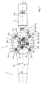
- the reversal device of the invention is represented on the figures 1 and 2 ; only the components necessary for understanding the reversal process have been illustrated.
- the turning device is intended to cooperate with a conveyor which brings a succession of components in a first position, for example with the tabs at the bottom, and resumes in the inverted position, for example with the tabs at the top.
- the conveyor is constituted by a rotary barrel 3 with vertical axis of which only an angular portion of the periphery 30 is shown schematically.
- the barrel comprises for example 16 or 32 peripheral locations on which are arranged treatment stations.
- the rotational movements of the barrel are preferably indexed; the components to be treated pass from one location to another at each step and thus successively browse these different processing stations to be tested, marked, packaged, etc.
- the reversal device of the invention occupies two successive locations of the barrel 3.
- the electronic components to be returned are removed from the barrel at a first location and placed on a first location A of the turntable 1 of the turning device.
- the turntable 1 is horizontal; it is rotated in an indexed manner by the electric motor 4 (for example a DC motor or a stepper motor) so as to traverse the four successive locations ABCD.
- the component is returned between locations B and C and discharged from turntable 1 to location D, where it joins a second location of the barrel 3.
- the reference 31 on the figure 1 indicates the radius of the first location of the barrel, from which are extracted the electronic compounds loaded on the turntable.
- the reference 32 corresponds to the radius of the second location where the components returned from the last location D of the turntable are positioned.
- the component to be returned is placed on the component holder 20 at the location A from the barrel 3 by means of placement not shown.
- the placement means as well as the shape of the component holder collaborate so that the position of the component on the component holder is accurately determined, and reproducibly from one component to another.
- the component holder 20 is provided with a nozzle 201, connected to a not shown pneumatic channel, which makes it possible to suck or blow air in order to keep the component in place or, on the contrary, to push it back.
- the pneumatic circuit also makes it possible to generate a stable "neutral point" in which the component is neither pushed nor sucked; a command makes it possible to pass it directly to this neutral point.
- the pneumatic channel preferably comprises a circular path, not shown, allowing the nozzle to remain connected to the channel during its rotations.
- the component door 20 is articulated around the axis of turning parallel to the horizontal plate 200.
- a spring 203 visible on the figure 2 , maintains the component holder 20 in the substantially horizontal position illustrated on the figures 1 and 2 .
- the spring 203 is stretched between the axis 20X, integral with the part 20, and the axis 20Y integral with the frame.
- the component holder 20 may preferably pivot at least 180 ° about the axis 200 so as to return the component relative to a horizontal plane while moving it.
- the axis 200 is positioned above the plane of the component holder on which is placed the component to be returned, in the middle of the thickness of the component, so as to allow the reversal of a component door to the location B by above another component holder at the location C, the nozzles of the two component holders then being aligned around the same vertical axis.
- a dimension of the component at the location B is aligned with the radius 31 which leads to the center of the barrel 3 through the first location of the barrel.
- the axis of rotation 200 of the component holder at the location B is however parallel to the axis of symmetry 33 between two successive locations of the barrel.
- the overturning of the component holder to the location B is actuated by the turning motor 21, for example a DC rotary motor or a stepper motor.
- the axis 210 of rotation of the motor 21 is horizontal and in the same plane as the turning axis 200. In the preferred embodiment illustrated, the axis 210 and the axis 200 are even coincident.
- the motor drives an eccentric part 22 whose end is provided with a slot 220 which makes it possible to receive a horizontal rod 202 connected to the component holder at the location B.
- a kinematic connection between the motor 21 and the component holder 20 therefore exists only when the latter is in the location B.
- the eccentric part 22 is thus arranged to mesh only with the rod 202 associated with the component holder at the location B.
- Rotation of the motor drives the rod 202 in a direction having a vertical component, thereby lifting the component holder against the force of the spring 203 and returning it about the axis 200, until it is superimposed on the component holder at location C.
- the component can then be deposited on the component holder at location C by controlling the pneumatic pressure on the nozzles 201 appropriately, as described below.
- the cycle traveled by one by one component between locations A and D of the turntable leaves the barrel 3 and is placed on the slot A of the component holder.
- the pneumatic circuit is controlled to hold the component in place by sucking air through the nozzle 201 at that location.
- Other means for holding the component may be used in the context of the invention, including mechanical gripping means.
- the motor 4 then rotates the turntable 1 with the four component holders 90 ° counter-clockwise, so that the component is now found at the start position of reversal B.
- the precise amplitude of the rotation is preferably controlled by means of an angular encoder providing a feedback signal to a control electronics of the motor 4.
- the rod 202 associated with the component holder is housed in the slot 220 of the eccentric part 22.
- the reversal is then effected by means of the motor 21 which actuates the eccentric part 22 so as to lift the component holder 20 to the location B and to rotate it 180 ° about the axis 200.
- the amplitude of the rotation of the motor 21 is controlled by means of a second angular encoder acting on the control current of the motor 21, or by means of end-of-travel detectors.
- the air gap under the nozzle 201 is maintained during inversion, so as to hold the component in place.
- the nozzle 201 of the component holder at the location C is actuated by the pneumatic system so as to create a slight vacuum of air, or a neutral pressure.
- the pneumatic system is controlled so as to interrupt the suction of air through the nozzle connected to the returned component holder B, and to create or increase the air gap of the nozzle connected to the component holder C. It is even possible to create a slight overpressure in the pneumatic circuit connected to the component holder B, so as to repel the component. The component is thus detached from the component holder B, and attracted by the component holder C, its position being accurately controlled.
- the component holder B then returns to its initial location B.
- it is returned to its initial location by means of the motor 21 which goes back and forth to replace the component holder in its position B.
- This variant has however the disadvantage of requiring a bidirectional motor 21, and require inversions of its direction of rotation, which slows the process.
- the spring 203 is used to return the component holder to its initial position.
- the rotary plate 1 resumes its rotation in the counterclockwise direction, until the rod 201 is disengaged from the slot 220 of the eccentric part.
- the spring 203 then exerts a restoring force to return the component holder to its initial position B.
- the cycle continues with rotation of the turntable by 90 ° in the counterclockwise cycle.
- the component thus passes from the location C to the location D, where it can be discharged from the turntable 1 and transferred in the inverted position on the conveyor.
- the turntable 1 has 4 locations for components 1. It is of course possible to start a new turnaround cycle of the next component before the first component has left the tray.
- a new component is loaded on slot A with each rotation of the tray, and a returned component is simultaneously discharged from slot D.
- no position of the barrel remains empty: at each step, a component is unloaded on slot A, and another returned component is loaded from slot D.
- the reversing device of the invention comprises four successive locations A, B, C and D.
- the component to be returned could be loaded directly to the start of rollover position, or directly unloaded from the end of rollover position, in order to reduce the number of locations.
- intermediate locations for intermittent storage or to perform additional operations for example additional turning operations along the same axis 200 or other orthogonal axis, for example.
- marking operations, testing, sorting, for example could also be performed on these intermediate locations.
- all the movements of the barrel, the engines 4 and 21, as well as the air pressures in the various chambers of the circuit pneumatic are preferably controlled by a control system not shown, for example a CNC-type programmable digital system.
- the control system can be programmed by a program that can be marketed or updated through appropriate computer data carriers.
- the turning device is associated with a circular barrel.
- the turning device is associated with another type of conveyor, for example a linear conveyor.
Landscapes
- Engineering & Computer Science (AREA)
- Manufacturing & Machinery (AREA)
- Microelectronics & Electronic Packaging (AREA)
- Specific Conveyance Elements (AREA)
Claims (19)
- Vorrichtung aufweisend:eine Drehscheibe (1) um umzudrehende elektronische Komponenten nacheinander zu den folgenden festen Orten zu fahren: Ein Ort (A) für das Laden der Komponenten auf die Drehscheibe (1), ein Ort (B) für den Beginn des Umdrehens, ein Ort (C) für das Ende des Umdrehens, und ein Ort (D) für das Entladen von der Drehscheibe (1);eine Umdrehvorrichtung (2) zum Umdrehen der elektronischen Komponenten zwischen dem Ort für den Beginn des Umdrehens und dem Ort für das Ende des Umdrehens,dadurch gekennzeichnet, dass
die Umdrehvorrichtung durch einen festen Drehmotor (21) angetrieben wird, der nicht mit der Drehscheibe verbunden ist. - Die Vorrichtung nach Anspruch 1, in der die festen Orte sich jeweils voneinander unterscheiden.
- Die Vorrichtung nach Anspruch 1 oder 2, in der die Umdrehvorrichtung ausgebildet ist, die elektronischen Komponenten um 180° um eine Umdrehachse parallel zu der Drehscheibe (200) umzudrehen.
- Die Vorrichtung nach einem der Ansprüche 1 bis 3, aufweisend eine pneumatische Vorrichtung kooperierend mit der Drehscheibe (1) für das Halten und Wegdrücken der elektronischen Komponenten.
- Die Vorrichtung nach einem der Ansprüche 1 bis 4, aufweisend Steuermittel ausgebildet die Drehscheibe (1) in diskreten Schritten immer in die gleiche Richtung um eine Vertikale Achse zu drehen.
- Die Vorrichtung nach einem der Ansprüche 1 bis 5, wobei der feste Drehmotor (21) eine Achse (210) parallel zu der Drehscheibe aufweist.
- Die Vorrichtung nach einem der Ansprüche 1 bis 6, wobei die Umdrehvorrichtung mindestens einen Komponententräger (20) aufweist, der mit der Drehscheibe (1) verbunden ist und um eine zu der Drehscheibe parallele Umdrehachse (200) drehbar ist und durch den festen Motor (21) so angetrieben werden kann, dass der Komponententräger (20) zwischen dem Ort für den Beginn des Umdrehens (B) und dem Ort für das Ende des Umdrehens (C) umgedreht werden kann, um dort die elektronische Komponente in die umgedrehte Position zu bringen.
- Die Vorrichtung nach Anspruch 7, wobei die Achse des festen Motors (210) und die Umdrehachse (200) in der gleichen vertikalen Ebene liegen.
- Die Vorrichtung nach Anspruch 8, wobei die Achse des festen Motors (210) und die Umdrehachse (200) zusammenfallen.
- Die Vorrichtung nach einem der Ansprüche 7 bis 9, aufweisend ein exzentrisches Teil (22), das durch den festen Motor (21) um die Umdrehachse (200) drehend angetrieben ist und das zum sukzessiven ineinandergreifen von nachfolgenden Komponententrägers (20) an dem Ort für den Beginn der Umdrehens (B) ausgebildet ist.
- Die Vorrichtung nach Anspruch 10, wobei das exzentrische Teil (22) und der Komponententräger (20) so ausgebildet sind, dass sie relative zueinander entlang einer horizontalen Richtung gleiten können und dass sie entlang einer vertikalen Richtung fest zueinander fest verbunden sind.
- Die Vorrichtung nach einem der Ansprüche 1 bis 11, wobei die elektronische Komponente um eine vertikale Achse um einen von Null verschiedenen Winkel zwischen dem Ort für den Beginn des Umdrehens und dem Ort für das Ende des Umdrehens drehbar ist.
- Ein Verfahren zum Umdrehen elektronischer Komponenten aufweisend:Laden der umzudrehenden elektronischen Komponente an einen ersten Ort (A) einer Drehscheibe (1);Drehen der Drehscheibe (1), so dass die elektronische Komponente sich an einem Ort für den Beginn des Umdrehens (B) befindet;Umdrehen der elektronischen Komponente mittels einer Umdrehvorrichtung (2), so dass sich die elektronische Komponente in der umgedrehten Stellung an einem Ort für das Ende des Umdrehens befindet, der vom Ort für den Beginn des Umdrehens verschieden ist,Entladen der elektronischen Komponente von einem Entladeort,dadurch gekennzeichnet, dassdie Umdrehvorrichtung durch einen festen Drehmotor (21) angetrieben wird.
- Das Verfahren nach Anspruch 13, wobei die Drehscheibe (1) ausgebildet ist, nach dem Umdrehen und vor dem Entladen um 90° zu drehen.
- Das Verfahren nach Anspruch 13 oder 14, wobei mehrere elektronische Komponenten gleichzeitig an mehreren Orten der Drehscheibe (1) positioniert werden.
- Das Verfahren nach einem der Ansprüche 13 bis 15, wobei die Drehscheibe durch einen Drehmotor (4) angetrieben wird,
und wobei der Motor der Drehscheibe und der Umdrehvorrichtung beide eine schrittweise Drehung in eine einzelne Richtung durchführen. - Das Verfahren nach einem der Ansprüche 11 bis 16, wobei die Verschiebung der elektronischen Komponenten während des Umdrehens eine Kombination aus dem Umdrehen um eine horizontale Achse und einer Winkeldrehung α um eine vertikale Achse ist.
- Das Verfahren nach einem der Ansprüche 11 bis 17, wobei der feste Drehmotor (4) in den Komponententräger (20) des Orts für den Beginn des Umdrehens eingreift und nicht in den Komponententräger eingreift, wenn letztere gedreht ist.
- System aufweisend:eine Drehtrommel (3) zum Antreiben einer elektronischen Komponente (3) zwischen verschiedenen nacheinander folgenden Verarbeitungsorten an dem Aussenbereich der Drehtrommel (3),eine Umdrehvorrichtung nach Ansprüchen 1 bis 12, die zwischen zwei nacheinander folgenden Orten der Trommel montiert ist, um die elektronische Komponente zwischen diesen beiden Orten umzudrehen.
Applications Claiming Priority (2)
| Application Number | Priority Date | Filing Date | Title |
|---|---|---|---|
| CH18342005 | 2005-11-15 | ||
| PCT/EP2006/067910 WO2007057291A1 (fr) | 2005-11-15 | 2006-10-30 | Dispositif et procede de retournement de composants electroniques |
Publications (2)
| Publication Number | Publication Date |
|---|---|
| EP1949779A1 EP1949779A1 (de) | 2008-07-30 |
| EP1949779B1 true EP1949779B1 (de) | 2013-02-13 |
Family
ID=37741172
Family Applications (1)
| Application Number | Title | Priority Date | Filing Date |
|---|---|---|---|
| EP06819183A Not-in-force EP1949779B1 (de) | 2005-11-15 | 2006-10-30 | Vorrichtung und verfahren zum kippen von elektronischen bauelementen |
Country Status (6)
| Country | Link |
|---|---|
| US (1) | US7716819B2 (de) |
| EP (1) | EP1949779B1 (de) |
| KR (1) | KR101241067B1 (de) |
| CN (1) | CN101310579B (de) |
| MY (1) | MY143902A (de) |
| WO (1) | WO2007057291A1 (de) |
Families Citing this family (1)
| Publication number | Priority date | Publication date | Assignee | Title |
|---|---|---|---|---|
| US10056278B2 (en) | 2016-08-22 | 2018-08-21 | Asm Technology Singapore Pte Ltd | Apparatus and method for transferring electronic devices |
Family Cites Families (11)
| Publication number | Priority date | Publication date | Assignee | Title |
|---|---|---|---|---|
| US2240093A (en) * | 1939-08-30 | 1941-04-29 | Hazel Atlas Glass Co | Apparatus for handling glassware |
| GB1012915A (en) * | 1962-07-09 | 1965-12-08 | Perrier Rene | Improved machine adapted to turn bottles, flasks and the like articles upside down |
| US4057149A (en) * | 1976-02-17 | 1977-11-08 | Rogers And Clarke Manufacturing Co. | Mechanism for transferring parts |
| JPS52156475A (en) * | 1976-06-23 | 1977-12-26 | Hitachi Ltd | Device for inverting/feeding parts |
| US4135630A (en) * | 1977-12-08 | 1979-01-23 | Universal Instruments Corporation | Centering device for automatic placement of chip components in hybrid circuits |
| US4666358A (en) * | 1985-01-31 | 1987-05-19 | Felix Wojciechowski | Apparatus for handling parts |
| DE4022486C1 (en) * | 1990-07-14 | 1991-08-08 | Hermann 8404 Woerth De Kronseder | Bottle reverser or inverter - uses gripping head opened and closed by first cam and swivelled by second cam |
| US5403146A (en) | 1993-05-18 | 1995-04-04 | Triway Machine Ltd. | Apparatus for manipulating a workpiece in a machining operation |
| US6468023B1 (en) | 1998-12-02 | 2002-10-22 | Delta Design, Inc. | Apparatus and method for inverting an IC device |
| TW460906B (en) * | 1999-03-05 | 2001-10-21 | Siemens Ag | Equipment to insert a substrate with flip-chips |
| AU2003298860A1 (en) * | 2002-09-06 | 2004-03-29 | Ismeca Semiconductor Holding Sa | Device for turning over electronic components |
-
2006
- 2006-10-30 EP EP06819183A patent/EP1949779B1/de not_active Not-in-force
- 2006-10-30 KR KR1020087011475A patent/KR101241067B1/ko not_active Expired - Fee Related
- 2006-10-30 CN CN2006800424498A patent/CN101310579B/zh not_active Expired - Fee Related
- 2006-10-30 MY MYPI20081571A patent/MY143902A/en unknown
- 2006-10-30 WO PCT/EP2006/067910 patent/WO2007057291A1/fr not_active Ceased
-
2008
- 2008-05-14 US US12/120,551 patent/US7716819B2/en not_active Expired - Fee Related
Also Published As
| Publication number | Publication date |
|---|---|
| KR20080069997A (ko) | 2008-07-29 |
| HK1123669A1 (en) | 2009-06-19 |
| KR101241067B1 (ko) | 2013-03-11 |
| CN101310579A (zh) | 2008-11-19 |
| EP1949779A1 (de) | 2008-07-30 |
| US7716819B2 (en) | 2010-05-18 |
| MY143902A (en) | 2011-07-29 |
| CN101310579B (zh) | 2011-01-12 |
| WO2007057291A1 (fr) | 2007-05-24 |
| US20080273950A1 (en) | 2008-11-06 |
Similar Documents
| Publication | Publication Date | Title |
|---|---|---|
| EP2821127B1 (de) | Rüttelvorrichtung und -verfahren | |
| FR2726543A1 (fr) | Ensemble a etoile centrale a changement rapide pour une machine de bouchage | |
| FR2635634A1 (de) | ||
| EP2051918B1 (de) | Vorrichtung zum umdrehen von behältern | |
| EP1989115B1 (de) | Vorrichtung zum füllen eines behälters | |
| EP1934122A1 (de) | Verfahren zum automatischen und sequenziellen laden von gegenständen und entsprechende ausrüstung | |
| FR2988183A1 (fr) | Machine d'insolation de panneaux munie d'un retourneur de panneau | |
| EP0589771B1 (de) | Herstellungsvorrichtung für Chipkarten | |
| CH664110A5 (fr) | Machine automatique de placement de composants sur des substrats, tete de placement pour cette machine. | |
| WO2007057291A1 (fr) | Dispositif et procede de retournement de composants electroniques | |
| FR2780961A1 (fr) | Dispositifs de chargement et dechargement pour machine d'impression | |
| FR2826350A1 (fr) | Dispositif de transfert de supports de pile et machine d'impression comportant un tel dispositif | |
| FR2932717A1 (fr) | Machine a imprimer. | |
| EP0112193A1 (de) | Vorrichtung zur zweistufigen serienmässigen Behandlung von rotationssymmetrischen Gegenständen, z.B. in der Munitionsfertigung | |
| FR2972951A1 (fr) | Systeme de chargement-dechargement de grandes palettes porte-piece pour machine-outil | |
| FR2891264A1 (fr) | Mecanisme d'evacuation destine a une machine d'inspection de verre de type distributeur en etoile | |
| EP0012081B1 (de) | Vorrichtung zum Aufstapeln und Entnehmen einzelner Platten von einem Stapel, insbesondere von Glasscheiben, auf einer Fördervorrichtung | |
| EP0015850B1 (de) | Transportvorrichtung für kleine Stücke | |
| FR2897555A1 (fr) | Machine et procede de marquage de pieces de forme | |
| FR2643348A1 (fr) | Dispositif d'acheminement de pieces avec ou sans retournement en vue de leur empilage dans au moins un recipient | |
| WO2004023858A1 (fr) | Dispositif pour le retournement de composants electroniques | |
| FR2670191A1 (fr) | Appareil automatique de separation et d'amenee de puces. | |
| EP1543965A1 (de) | Siebdruckmaschine mit einer Vorrichtung zur Übergabe von Druckobjekten | |
| EP0475827A1 (de) | Übergabevorrichtung für Gegenstände verschiedener Art zur Konditionierung derselben | |
| FR2839987A1 (fr) | Dispositif et installation de transfert, entre un poste de stockage et au moins une forme d'un poste de formage ou de couture ou de repassage, de tubes tricotes |
Legal Events
| Date | Code | Title | Description |
|---|---|---|---|
| PUAI | Public reference made under article 153(3) epc to a published international application that has entered the european phase |
Free format text: ORIGINAL CODE: 0009012 |
|
| 17P | Request for examination filed |
Effective date: 20080315 |
|
| AK | Designated contracting states |
Kind code of ref document: A1 Designated state(s): AT BE BG CH CY CZ DE DK EE ES FI FR GB GR HU IE IS IT LI LT LU LV MC NL PL PT RO SE SI SK TR |
|
| DAX | Request for extension of the european patent (deleted) | ||
| GRAP | Despatch of communication of intention to grant a patent |
Free format text: ORIGINAL CODE: EPIDOSNIGR1 |
|
| GRAS | Grant fee paid |
Free format text: ORIGINAL CODE: EPIDOSNIGR3 |
|
| GRAA | (expected) grant |
Free format text: ORIGINAL CODE: 0009210 |
|
| AK | Designated contracting states |
Kind code of ref document: B1 Designated state(s): AT BE BG CH CY CZ DE DK EE ES FI FR GB GR HU IE IS IT LI LT LU LV MC NL PL PT RO SE SI SK TR |
|
| REG | Reference to a national code |
Ref country code: GB Ref legal event code: FG4D Free format text: NOT ENGLISH |
|
| REG | Reference to a national code |
Ref country code: AT Ref legal event code: REF Ref document number: 597088 Country of ref document: AT Kind code of ref document: T Effective date: 20130215 |
|
| REG | Reference to a national code |
Ref country code: IE Ref legal event code: FG4D Free format text: LANGUAGE OF EP DOCUMENT: FRENCH |
|
| REG | Reference to a national code |
Ref country code: DE Ref legal event code: R096 Ref document number: 602006034554 Country of ref document: DE Effective date: 20130404 |
|
| REG | Reference to a national code |
Ref country code: NL Ref legal event code: VDEP Effective date: 20130213 |
|
| REG | Reference to a national code |
Ref country code: LT Ref legal event code: MG4D |
|
| PG25 | Lapsed in a contracting state [announced via postgrant information from national office to epo] |
Ref country code: ES Free format text: LAPSE BECAUSE OF FAILURE TO SUBMIT A TRANSLATION OF THE DESCRIPTION OR TO PAY THE FEE WITHIN THE PRESCRIBED TIME-LIMIT Effective date: 20130524 Ref country code: IS Free format text: LAPSE BECAUSE OF FAILURE TO SUBMIT A TRANSLATION OF THE DESCRIPTION OR TO PAY THE FEE WITHIN THE PRESCRIBED TIME-LIMIT Effective date: 20130613 Ref country code: SE Free format text: LAPSE BECAUSE OF FAILURE TO SUBMIT A TRANSLATION OF THE DESCRIPTION OR TO PAY THE FEE WITHIN THE PRESCRIBED TIME-LIMIT Effective date: 20130213 Ref country code: BG Free format text: LAPSE BECAUSE OF FAILURE TO SUBMIT A TRANSLATION OF THE DESCRIPTION OR TO PAY THE FEE WITHIN THE PRESCRIBED TIME-LIMIT Effective date: 20130513 Ref country code: LT Free format text: LAPSE BECAUSE OF FAILURE TO SUBMIT A TRANSLATION OF THE DESCRIPTION OR TO PAY THE FEE WITHIN THE PRESCRIBED TIME-LIMIT Effective date: 20130213 |
|
| PG25 | Lapsed in a contracting state [announced via postgrant information from national office to epo] |
Ref country code: SI Free format text: LAPSE BECAUSE OF FAILURE TO SUBMIT A TRANSLATION OF THE DESCRIPTION OR TO PAY THE FEE WITHIN THE PRESCRIBED TIME-LIMIT Effective date: 20130213 Ref country code: LV Free format text: LAPSE BECAUSE OF FAILURE TO SUBMIT A TRANSLATION OF THE DESCRIPTION OR TO PAY THE FEE WITHIN THE PRESCRIBED TIME-LIMIT Effective date: 20130213 Ref country code: PL Free format text: LAPSE BECAUSE OF FAILURE TO SUBMIT A TRANSLATION OF THE DESCRIPTION OR TO PAY THE FEE WITHIN THE PRESCRIBED TIME-LIMIT Effective date: 20130213 Ref country code: FI Free format text: LAPSE BECAUSE OF FAILURE TO SUBMIT A TRANSLATION OF THE DESCRIPTION OR TO PAY THE FEE WITHIN THE PRESCRIBED TIME-LIMIT Effective date: 20130213 Ref country code: PT Free format text: LAPSE BECAUSE OF FAILURE TO SUBMIT A TRANSLATION OF THE DESCRIPTION OR TO PAY THE FEE WITHIN THE PRESCRIBED TIME-LIMIT Effective date: 20130613 Ref country code: GR Free format text: LAPSE BECAUSE OF FAILURE TO SUBMIT A TRANSLATION OF THE DESCRIPTION OR TO PAY THE FEE WITHIN THE PRESCRIBED TIME-LIMIT Effective date: 20130514 |
|
| PG25 | Lapsed in a contracting state [announced via postgrant information from national office to epo] |
Ref country code: DK Free format text: LAPSE BECAUSE OF FAILURE TO SUBMIT A TRANSLATION OF THE DESCRIPTION OR TO PAY THE FEE WITHIN THE PRESCRIBED TIME-LIMIT Effective date: 20130213 Ref country code: SK Free format text: LAPSE BECAUSE OF FAILURE TO SUBMIT A TRANSLATION OF THE DESCRIPTION OR TO PAY THE FEE WITHIN THE PRESCRIBED TIME-LIMIT Effective date: 20130213 Ref country code: CZ Free format text: LAPSE BECAUSE OF FAILURE TO SUBMIT A TRANSLATION OF THE DESCRIPTION OR TO PAY THE FEE WITHIN THE PRESCRIBED TIME-LIMIT Effective date: 20130213 Ref country code: NL Free format text: LAPSE BECAUSE OF FAILURE TO SUBMIT A TRANSLATION OF THE DESCRIPTION OR TO PAY THE FEE WITHIN THE PRESCRIBED TIME-LIMIT Effective date: 20130213 Ref country code: EE Free format text: LAPSE BECAUSE OF FAILURE TO SUBMIT A TRANSLATION OF THE DESCRIPTION OR TO PAY THE FEE WITHIN THE PRESCRIBED TIME-LIMIT Effective date: 20130213 Ref country code: RO Free format text: LAPSE BECAUSE OF FAILURE TO SUBMIT A TRANSLATION OF THE DESCRIPTION OR TO PAY THE FEE WITHIN THE PRESCRIBED TIME-LIMIT Effective date: 20130213 |
|
| PLBE | No opposition filed within time limit |
Free format text: ORIGINAL CODE: 0009261 |
|
| STAA | Information on the status of an ep patent application or granted ep patent |
Free format text: STATUS: NO OPPOSITION FILED WITHIN TIME LIMIT |
|
| PG25 | Lapsed in a contracting state [announced via postgrant information from national office to epo] |
Ref country code: IT Free format text: LAPSE BECAUSE OF FAILURE TO SUBMIT A TRANSLATION OF THE DESCRIPTION OR TO PAY THE FEE WITHIN THE PRESCRIBED TIME-LIMIT Effective date: 20130213 |
|
| 26N | No opposition filed |
Effective date: 20131114 |
|
| PGFP | Annual fee paid to national office [announced via postgrant information from national office to epo] |
Ref country code: GB Payment date: 20131021 Year of fee payment: 8 Ref country code: AT Payment date: 20131011 Year of fee payment: 8 |
|
| REG | Reference to a national code |
Ref country code: DE Ref legal event code: R097 Ref document number: 602006034554 Country of ref document: DE Effective date: 20131114 |
|
| BERE | Be: lapsed |
Owner name: ISMECA SEMICONDUCTOR HOLDING SA Effective date: 20131031 |
|
| PG25 | Lapsed in a contracting state [announced via postgrant information from national office to epo] |
Ref country code: MC Free format text: LAPSE BECAUSE OF FAILURE TO SUBMIT A TRANSLATION OF THE DESCRIPTION OR TO PAY THE FEE WITHIN THE PRESCRIBED TIME-LIMIT Effective date: 20130213 |
|
| REG | Reference to a national code |
Ref country code: CH Ref legal event code: PL |
|
| REG | Reference to a national code |
Ref country code: IE Ref legal event code: MM4A |
|
| PG25 | Lapsed in a contracting state [announced via postgrant information from national office to epo] |
Ref country code: LI Free format text: LAPSE BECAUSE OF NON-PAYMENT OF DUE FEES Effective date: 20131031 Ref country code: CH Free format text: LAPSE BECAUSE OF NON-PAYMENT OF DUE FEES Effective date: 20131031 |
|
| PG25 | Lapsed in a contracting state [announced via postgrant information from national office to epo] |
Ref country code: BE Free format text: LAPSE BECAUSE OF NON-PAYMENT OF DUE FEES Effective date: 20131031 |
|
| PG25 | Lapsed in a contracting state [announced via postgrant information from national office to epo] |
Ref country code: IE Free format text: LAPSE BECAUSE OF NON-PAYMENT OF DUE FEES Effective date: 20131030 |
|
| REG | Reference to a national code |
Ref country code: AT Ref legal event code: MM01 Ref document number: 597088 Country of ref document: AT Kind code of ref document: T Effective date: 20141030 |
|
| GBPC | Gb: european patent ceased through non-payment of renewal fee |
Effective date: 20141030 |
|
| PG25 | Lapsed in a contracting state [announced via postgrant information from national office to epo] |
Ref country code: TR Free format text: LAPSE BECAUSE OF FAILURE TO SUBMIT A TRANSLATION OF THE DESCRIPTION OR TO PAY THE FEE WITHIN THE PRESCRIBED TIME-LIMIT Effective date: 20130213 Ref country code: CY Free format text: LAPSE BECAUSE OF FAILURE TO SUBMIT A TRANSLATION OF THE DESCRIPTION OR TO PAY THE FEE WITHIN THE PRESCRIBED TIME-LIMIT Effective date: 20130213 |
|
| PG25 | Lapsed in a contracting state [announced via postgrant information from national office to epo] |
Ref country code: LU Free format text: LAPSE BECAUSE OF NON-PAYMENT OF DUE FEES Effective date: 20131030 Ref country code: GB Free format text: LAPSE BECAUSE OF NON-PAYMENT OF DUE FEES Effective date: 20141030 Ref country code: HU Free format text: LAPSE BECAUSE OF FAILURE TO SUBMIT A TRANSLATION OF THE DESCRIPTION OR TO PAY THE FEE WITHIN THE PRESCRIBED TIME-LIMIT; INVALID AB INITIO Effective date: 20061030 |
|
| PG25 | Lapsed in a contracting state [announced via postgrant information from national office to epo] |
Ref country code: AT Free format text: LAPSE BECAUSE OF NON-PAYMENT OF DUE FEES Effective date: 20141030 |
|
| REG | Reference to a national code |
Ref country code: FR Ref legal event code: PLFP Year of fee payment: 10 |
|
| REG | Reference to a national code |
Ref country code: FR Ref legal event code: PLFP Year of fee payment: 11 |
|
| PGFP | Annual fee paid to national office [announced via postgrant information from national office to epo] |
Ref country code: FR Payment date: 20161020 Year of fee payment: 11 |
|
| REG | Reference to a national code |
Ref country code: FR Ref legal event code: ST Effective date: 20180629 |
|
| PG25 | Lapsed in a contracting state [announced via postgrant information from national office to epo] |
Ref country code: FR Free format text: LAPSE BECAUSE OF NON-PAYMENT OF DUE FEES Effective date: 20171031 |
|
| PGFP | Annual fee paid to national office [announced via postgrant information from national office to epo] |
Ref country code: DE Payment date: 20191021 Year of fee payment: 14 |
|
| REG | Reference to a national code |
Ref country code: DE Ref legal event code: R082 Ref document number: 602006034554 Country of ref document: DE Representative=s name: BECK & ROESSIG - EUROPEAN PATENT ATTORNEYS, DE |
|
| REG | Reference to a national code |
Ref country code: DE Ref legal event code: R119 Ref document number: 602006034554 Country of ref document: DE |
|
| PG25 | Lapsed in a contracting state [announced via postgrant information from national office to epo] |
Ref country code: DE Free format text: LAPSE BECAUSE OF NON-PAYMENT OF DUE FEES Effective date: 20210501 |