EP1949525B1 - Elektromotor - Google Patents
Elektromotor Download PDFInfo
- Publication number
- EP1949525B1 EP1949525B1 EP06806352.8A EP06806352A EP1949525B1 EP 1949525 B1 EP1949525 B1 EP 1949525B1 EP 06806352 A EP06806352 A EP 06806352A EP 1949525 B1 EP1949525 B1 EP 1949525B1
- Authority
- EP
- European Patent Office
- Prior art keywords
- electric motor
- sensors
- fan
- motor according
- module
- Prior art date
- Legal status (The legal status is an assumption and is not a legal conclusion. Google has not performed a legal analysis and makes no representation as to the accuracy of the status listed.)
- Active
Links
Images


Classifications
-
- H—ELECTRICITY
- H02—GENERATION; CONVERSION OR DISTRIBUTION OF ELECTRIC POWER
- H02K—DYNAMO-ELECTRIC MACHINES
- H02K11/00—Structural association of dynamo-electric machines with electric components or with devices for shielding, monitoring or protection
- H02K11/20—Structural association of dynamo-electric machines with electric components or with devices for shielding, monitoring or protection for measuring, monitoring, testing, protecting or switching
- H02K11/21—Devices for sensing speed or position, or actuated thereby
Definitions
- the invention relates to an electric motor.
- the invention is therefore the object of developing an electric motor, where it should be made more compact and cheaper.
- the object is achieved in the electric motor according to the features indicated in claim 1.
- the electric motor comprises a fan with fan, which is at least partially surrounded by a fan cover, the fan wheel is connected to a rotor shaft of the electric motor, wherein the fan wheel is connected at its one axial end region with a signal disc, which cooperate with sensors of a module which is provided on the fan cowl, the sensors being arranged axially behind the signal disk, wherein the signal disk is made of metallic material, in particular sheet metal, or at least comprises metallic particles, wherein the signal disk is non-positively connected in the axial direction and additionally in the circumferential direction in a form-fitting manner with the fan wheel, the module having sensors and an electronics housing (6) detachably connectable to the fan cover, wherein the module comprises three positions for receiving the sensors, wherein the sensors are provided only at two of the three positions.
- the advantage here is that it is more compact, since the sensors are integrated in the module.
- the relative distance of the sensors is determined via the module and thus eliminates a source of error.
- no part protrudes in the radial direction.
- the slightly larger length is only a small disadvantage. Damage or collisions in the case of an axially bolted module occur only to a limited extent or not at all.
- the module is housing-forming and protects the integrated sensors.
- the function of the signal disk is advantageously separate from the function of the fan wheel.
- the moment of inertia is reducible by the choice of suitable Material reducible at the fan.
- the signal disk can be chosen from metal or magnetizable material.
- the signal disk is easily and quickly replaceable by a signal disk with a different number of webs.
- a high variance of electric motors can be produced, with only a few different parts being needed.
- a respective electric motor can be produced which in each case has different angular resolutions.
- the signal disk is made of metallic material, in particular sheet metal, or comprises at least metallic particles.
- the fan is made of plastic, in particular as an injection molded part.
- plastic in particular as an injection molded part.
- the fan wheel is connected to the rotor shaft.
- the cooling air flow generated by the fan improves the heat dissipation of the electric motor to the environment.
- the advantage here is that the cooling air flow is generated depending on the speed of the motor. Thus, a lot of cooling power is generated when the engine has high power and vice versa. The fan does not consume power when the speed disappears.
- the signal disk in the circumferential direction is positively connected and connected in the axial direction non-positively with the fan.
- the advantage here is that the connection by simple slots on the signal disk and the fan wheel protruding, widening pin can be produced.
- the module has sensors and an electronics housing that can be detachably connected to the fan cover.
- the advantage here is that the relative distance between the sensors can be fixed and can be protected by means of the module.
- the sensors are electrically arranged in the circumferential direction with an offset of 90 °. This is advantageous, for example, if the number of pulses of the signal disk is 1, that is, only one recess per revolution is detectable.
- the advantage here is that two signals can be generated with a 90 ° phase shift and thus a rotation direction identifier can be realized.
- the module comprises three positions for receiving sensors.
- the advantage here is that two of the three positions are selectable. so only these two are equipped.
- the module comprises a connector part.
- the advantage here is that a bus cable with corresponding mating connector part is connectable.
- the module does not comprise a connector part but is directly connectable with Kable in the interior of the junction box of the electric motor.
- the module is designed as a bus subscriber.
- the advantage here is that the evaluation electronics and the bus subscriber electronics with address is already provided in the module and thus the drive with electric motor is able to be connected to a bus system.
- the data is then interchangeable with other subscribers, such as a converter supplying the electric motor, decentralized control, central computer, PLC and the like.
- the speed can be supplied to these participants for controlling and / or regulating.
- the working range of the sensors is greater than the manufacturing tolerances of the fan guard and the fan wheel.
- a mechanical adjustment is not necessary and there are associated adjustment means superfluous. Because the module is simply connected to the fan cover and the permissible work area covers more than the above tolerances that arise when manufacturing the fan and the fan cover, and more that arise during assembly of the electric motor. Another advantage is that for fan and fan cover plastic parts are usable despite their large tolerance.
- a signal disc On the fan blade 3 comprehensive fan 4, a signal disc is provided which has circumferentially successive areas of recesses 1 and material.
- the material areas are exemplary sheet metal areas 2 of the signal disk.
- the regions are arranged in such a way that sensors arranged axially behind the signal disk can detect these in an alternating sequence when the signal disk is rotated.
- the sensors 30 can be attached to the fan cover 5.
- the sensors 30 are provided in an electronics housing 6, which is connected to means for releasable connection to the mounting portions 31.
- screws are advantageously used.
- a connector 7 is provided, which is suitable for connecting a corresponding mating connector.
- a fieldbus connection is preferably realized such that the electronics housing can be provided as a bus subscriber.
- the electronics housing is designed such that in addition to the sensors also includes an electronic circuit, which is an address assigned as a bus subscriber.
- the fan is sealed by means of a labyrinth seal 8 to the motor housing 9 of the electric motor.
- the fan is connected to the rotor 10 mounted on the housing part 9 rotor shaft and thus driven by this.
- the cooling air flow driven by the fan serves to cool the electric motor.
- FIG. 3 Within the electronics housing 6 are in FIG. 3 three sensors 30 arranged visible. However, according to the invention only two of the three sensors 30 are provided. In this case, the two sensors are advantageously selected, which cooperate with the signal disc such that when the first of the two is located above the middle of a ridge, the second begins to recognize the beginning of a ridge.
- the signal disk can be used in various embodiments and has, for example, only one, two or more recesses on the circumference, in each case only two positions are advantageous for the sensors.
- the third position can be dispensed with.
- the positions of the sensors are selected and the electronics housing 8 is shaped such that generates an advantageous pulse pattern in which the two signals are offset by 90 ° electrically.
- the sensors are arranged essentially at the same radius.
- the fan cover is connected to the axial end portion of the motor housing part 9.
- no connector is provided on the module, but it is a cable led out of the sensors out of the module until, for example, in the terminal box of the electric motor or to an external device.
- the positions of the sensors are selected as such and the electronics housing 6 is shaped in such a way that the sensors have an angle of 90 ° to one another.
- the electronics housing 6 is sealed and executed in a high degree of protection. Although it increases the overall length of the motor, but bothers little because it is located at the axial end portion and does not protrude in the radial direction.
- the signal disk can also be made of plastic, wherein metallic particles are provided in the plastic material instead of in the region of the material areas, in the region of the recesses either plastic without or with less metallic particles or alternatively instead of the plastic a recess, ie air.
- the signal disc can also be produced from a magnetizable material, wherein the material regions 1 are magnetized in such a way that a respective north pole is detectable in the axial direction, and wherein the regions 2 are embodied and magnetized such that a respective south pole can be detected in the axial direction is.
- the signals which can be output at the connector are available as incremental signal in HTL, TTL and sine-type design or as bus digital signal in exemplary interface such as ASI or CAN bus.
- the signal disk is metallic and the fan of plastic.
- the attachment of the signal disk is carried out on the pin 20 of the fan wheel.
- the pins 20 are integrally formed with the fan.
- the pins and corresponding recesses are formed on the signal disk such that in the circumferential direction a positive connection and in the axial direction a non-positive connection is performed.
- the pins widen in the axial direction towards the engine and thus allow even by simply plugging the signal disk a stable and firm connection.
Landscapes
- Engineering & Computer Science (AREA)
- Microelectronics & Electronic Packaging (AREA)
- Power Engineering (AREA)
- Structures Of Non-Positive Displacement Pumps (AREA)
- Motor Or Generator Cooling System (AREA)
Description
- Die Erfindung betrifft einen Elektromotor.
- Aus der
DE 199 24 201 C2 ist ein Winkelerfassungssystem gezeigt, bei dem die Sensoren am Umfang angeordnet sind, so dass in radialer Richtung sehr viel Bauraum benötigt wird. An den herausstehenden Impulsgebern können bei Transport des Motors Schäden auftreten oder vorbeibewegende Objekte oder Personen kollidieren. Außerdem sind die Impulsgeber in ihrer relativen Position zueinander nur über die Lüfterhaube festlegbar ist. - Aus der
DE 102 43 273 A1 ist ein Elektromotor mit Lüfter und zugehörigem Lüfterrad bekannt, wobei eine Lüfterhaube den Lüfter zumindest teilweise umgibt, wobei vom Lüfter ein Signalgeber gehalten ist. - Aus der
JP 60 176439 A - Aus der
EP 0 192 469 A1 ist ein Elektromotor bekannt, bei dem der Lüfter eine optisch codierte Scheibe aufweist. - Der Erfindung liegt daher die Aufgabe zugrunde, einen Elektromotor weiterzubilden, wobei er kompakter und kostengünstiger ausgeführt sein soll.
- Erfindungsgemäß wird die Aufgabe bei dem Elektromotor nach den in Anspruch 1 angegebenen Merkmalen gelöst.
- Wichtige Merkmale der Erfindung bei dem Elektromotor sind, dass er einen Lüfter mit Lüfterrad umfasst, das von einer Lüfterhaube zumindest teilweise umgeben ist, das Lüfterrad mit einer Rotorwelle des Elektromotors verbunden ist,
wobei das Lüfterrad an seinem einen axialen Endbereich mit einer Signalscheibe verbunden ist, die mit Sensoren eines Moduls zusammenwirken, das an der Lüfterhaube vorgesehen ist,
wobei die Sensoren axial hinter der Signalscheibe angeordnet sind,
wobei die Signalscheibe aus metallischem Material, Insbesondere Blech, gefertigt ist oder zumindest metallische Partikel umfasst,
wobei die Signalscheibe in axialer Richtung kraftschlüssig und zusätzlich in Umfangsrichtung formschlüssig mit dem Lüfterrad verbunden ist,
wobei das Modul Sensoren und ein mit der Lüfterhaube lösbar verbindbares Elektronikgehäuse (6) aufweist,
wobei das Modul drei Positionen zur Aufnahme der Sensoren umfasst,
wobei die Sensoren nur an zwei der drei Positionen vorgesehen sind. - Von Vorteil ist dabei, dass er kompakter ist, da die Sensoren im Modul integriert ausgebildet sind. Außerdem ist der relative Abstand der Sensoren über das Modul festgelegt und somit eine Fehlerquelle beseitigt. Darüber hinaus steht in radialer Richtung nun kein Teil hervor. Die etwas größere Baulänge ist nur ein kleiner Nachteil. Beschädigungen oder Kollisionen bei axial angeschraubtem Modul treten nur in geringem Maße oder gar nicht auf. Insbesondere ist das Modul gehäusebildend und schützt die integrierten Sensoren.
- Des Weiteren ist vorteilhafterweise die Funktion der Signalscheibe getrennt von der Funktion des Lüfterrades. Somit ist das Trägheitsmoment reduzierbar durch die Wahl geeigneten Materials bei dem Lüfterrad reduzierbar. Trotzdem kann die Signalscheibe aus Metall oder magnetisierbarem Material gewählt werden.
- Außerdem ist die Signalscheibe einfach und schnell durch eine Signalscheibe mit einer anderen Anzahl von Stegen ersetzbar. Somit ist innerhalb einer Baureihe von Elektromotoren eine hohe Varianz an Elektromotoren herstellbar, wobei nur wenige verschiedene Teile benötigt werden. Denn es ist nur die Signalscheibe in verschiedenen Ausführungen zu bevorraten, um Elektromotoren mit verschiedener Winkelauflösung bereitzustellen. Wenn also nur eine Varianz in der Signalscheibe vorhanden ist, insbesondere in der Anzahl der Impulse, welche bei einer Umdrehung abgebbar sind, ist somit ein jeweiliger Elektromotor herstellbar, der jeweils verschiedene Winkelauflösungen aufweist.
- Erfindungsgemäß ist die Signalscheibe aus metallischem Material, insbesondere Blech, gefertigt oder umfasst zumindest metallische Partikel. Von Vorteil ist dabei, dass die Funktion des Signalgebers in Form der Signalscheibe realisierbar ist und trotzdem das Trägheitsmoment gering ausführbar ist.
- Bei einer vorteilhaften Ausgestaltung ist das Lüfterrad aus Kunststoff gefertigt, insbesondere als Spritzgussteil. Von Vorteil ist dabei, dass die Herstellung einfach und schnell ausführbar ist und das Trägheitsmoment gering ausführbar ist. Somit ist die Dynamik bei Servo- und Positionieranwendungen besonders hoch.
- Erfindungsgemäß ist das Lüfterrad mit der Rotorwelle verbunden. Insbesondere verbessert der vom Lüfter erzeugte Kühlluftstrom die Wärmeabfuhr des Elektromotors an die Umgebung. Von Vorteil ist dabei, dass der Kühlluftstrom abhängig von der Drehzahl des Motors erzeugt wird. Somit wird viel Kühlleistung erzeugt, wenn der Motor eine hohe Leistung aufweist und umgekehrt. Der Lüfter verbraucht keine Leistung, wenn die Drehzahl verschwindet.
- Erfindungsgemäß ist die Signalscheibe in Umfangsrichtung formschlüssig und in axialer Richtung kraftschlüssig mit dem Lüfterrad verbunden. Von Vorteil ist dabei, dass die Verbindung durch einfache Schlitze an der Signalscheibe und am Lüfterrad hervorstehende, sich verbreiternde Zapfen herstellbar ist.
- Erfindungsgemäß weist das Modul Sensoren und ein mit der Lüfterhaube lösbar verbindbares Elektronikgehäuse auf. Von Vorteil ist dabei, dass der relative Abstand zwischen den Sensoren festlegbar ist und schützbar ist mittels des Moduls.
- Bei einer vorteilhaften Ausgestaltung sind die Sensoren in Umfangsrichtung mit einem Versatz von jeweils 90° elektrisch angeordnet. Dies ist beispielsweise von Vorteil, wenn die Impulszahl der Signalscheibe 1 ist, also pro Umdrehung nur eine Ausnehmung detektierbar ist. Von Vorteil Ist dabei, dass zwei Signale mit einer 90° Phasenverschiebung erzeugbar sind und somit eine Drehrichtungskennung realisierbar ist.
- Erfindungsgemäß umfasst das Modul drei Positionen zur Aufnahme von Sensoren. Von Vorteil ist dabei, dass zwei der drei Positionen auswählbar sind. sind also nur diese zwei bestückt.
- Es sind also nur an zwei der drei Positionen Sensoren vorgesehen.
- Bei einer vorteilhaften Ausgestaltung umfasst das Modul ein Steckverbinderteil. Von Vorteil ist dabei, dass ein Buskabel mit entsprechendem Gegensteckverbinderteil verbindbar ist.
- Bei einer alternativen vorteilhaften Ausgestaltung umfasst das Modul kein Steckverbinderteil sondern ist mit Kable direkt verbindbar in den Innenbereich des Anschlusskastens des Elektromotors.
- Bei einer vorteilhaften Ausgestaltung ist das Modul als Busteilnehmer ausgeführt. Von Vorteil ist dabei, dass die Auswertelektronik und die Busteilnehmerelektronik mit Adresse schon im Modul vorgesehen ist und somit der Antrieb mit Elektromotor fähig ist, mit einem Bussystem verbunden zu werden. Die Daten sind dann mit weiteren Teilnehmern, wie einem den Elektromotor versorgenden Umrichter, dezentrale Steuerung, Zentralrechner, SPS und dergleichen austauschbar. Insbesondere ist die Drehzahl diesen Teilnehmern zum Steuern und/oder Regeln zuführbar.
- Bei einer vorteilhaften Ausgestaltung ist der Arbeitsbereich der Sensoren größer als die Fertigungstoleranzen der Lüfterhaube und des Lüfterrades. Vorteiligerweise ist somit ein mechanisches Einstellen nicht notwendig und es sind zugehörige Verstellmittel überflüssig. Denn das Modul wird einfach an die Lüfterhaube verbunden und der zulässige Arbeitsbereich überdeckt mehr als die genannten Toleranzen, die beim Fertigen des Lüfterrades und der Lüfterhaube entstehen, sowie weitere, die beim Zusammenbau des Elektromotors entstehen. Vorteil ist auch, dass für Lüfterrad und Lüfterhaube Kunststoffteile trotz deren großer Toleranz verwendbar sind.
- Weitere Vorteile ergeben sich aus den Unteransprüchen.
-
1 Ausnehmung der Signalscheibe 2 Blechbereiche der Signalscheibe 3 Lüfterflügel 4 Lüfterrad 5 Lüfterhaube 6 Elektronikgehäuse 7 Steckverbinder 8 Labyrinth-Dichtung 9 Motorgehäuseteil 10 Lager 20 Zapfen 30 Sensor 31 Befestigungsbereiche - Die Erfindung wird nun anhand von Abbildungen näher erläutert:
- In der
Figur 1 a ist ein axialer Endbereich eines erfindungsgemäßen Elektromotors mit Lüfter in Schnittansicht gezeichnet. - In
Figur 1b ist eine Schrägansicht auf diesen Bereich gezeigt. - In
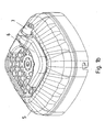
Figur 2 ist das Lüfterrad des Lüfters gezeigt. - In
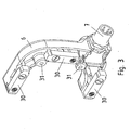
Figur 3 Ist das Elektronikgehäuse 6 gezeigt, das an der Lüfterhaube 5 anbringbar ist. - Am Lüfterflügel 3 umfassenden Lüfterrad 4 ist eine Signalscheibe vorgesehen, die in Umfangsrichtung aufeinander folgende Bereiche von Ausnehmungen 1 und Material aufweist. Die Materialbereiche sind beispielhaft Blechbereiche 2 der Signalscheibe.
- Die Bereiche sind derart angeordnet, dass axial hinter der Signalscheibe angeordnete Sensoren diese beim Drehen der Signalscheibe abwechselnde Reihenfolge detektieren können.
- Die Sensoren 30 sind an der Lüfterhaube 5 anbringbar. Hierzu sind die Sensoren 30 in einem Elektronikgehäuse 6 vorgesehen, das mit Mitteln zur lösbaren Verbindung an den Befestigungsbereichen 31 verbunden ist. Hierzu sind vorteiligerweise Schrauben verwendbar. Am Elektronikgehäuse 6 ist ein Steckverbinder 7 vorgesehen, der zum Anschließen eines entsprechenden Gegensteckverbinders geeignet ist. Vorzugsweise ist hierbei ein Feldbusanschluss derart realisiert, dass das Elektronikgehäuse als Busteilnehmer vorsehbar ist. Hierzu ist das Elektronikgehäuse derart ausgeführt, dass es zusätzlich zu den Sensoren auch noch eine elektronische Schaltung umfasst, der eine Adresse als Busteilnehmer zuordenbar ist.
- Das Lüfterrad ist mittels einer Labyrinth-Dichtung 8 zum Motorgehäusetell 9 des Elektromotors hin abgedichtet. Das Lüfterrad ist mit der über die Lager 10 am Gehäuseteil 9 gelagerten Rotorwelle verbunden und somit von dieser angetrieben. Der vom Lüfterrad angetriebene Kühlluftstrom dient zur Kühlung des Elektromotors.
- Innerhalb der Elektronikgehäuses 6 sind in
Figur 3 drei Sensoren 30 sichtbar angeordnet. Erfindungsgemäß sind jedoch nur zwei der drei Sensoren 30 vorgesehen. Dabei sind vorteiligerweise die beiden Sensoren ausgewählt, welche derart mit der Signalscheibe zusammenwirken, dass, wenn der erste der beiden sich über der Mitte eines Steges befindet, sich der zweite den Beginn eines Steges zu erkennen beginnt. - Auf diese Weise entstehen bei der Drehbewegung phasenverschobene Signale, die zur Drehrichtungserkennung notwendig sind.
- Da die Signalscheibe in verschiedenen Ausführungen verwendbar ist und dabei beispielsweise nur eine, zwei oder mehr Ausnehmungen am Umfang aufweist, sind jeweils nur zwei Positionen für die Sensoren vorteilhaft. Auf die dritte Position kann je nach Bauart der Signalscheibe verzichtet werden. Vorteilig bei nur wenigen Ausnehmungen am Umfang ist, dass die elektrische Signal-Frequenz auch bei hohen Drehzahlen relativ niedrig ist. Zur verbesserten Winkelauflösung trägt allerdings eine höhere Anzahl von Ausnehmungen bei. Insgesamt sind daher besonders eine Anzahl von 6 oder 8 Ausnehmungen am Umfang vorteilig.
- Die Positionen der Sensoren sind derart gewählt und das Elektronikgehäuse 8 ist derart geformt, dass ein vorteilhaftes Pulsmuster erzeugt, bei dem die beiden Signale um elektrisch 90° versetzt sind. Die Sensoren sind dabei im Wesentlichen auf demselben Radius angeordnet.
- Die Lüfterhaube ist am axialen Endbereich des Motorgehäuseteils 9 verbunden.
- Bei einem weiteren Ausführungsbeispiel ist kein Steckverbinder am Modul vorgesehen, sondern es wird ein Kabel von den Sensoren aus dem Modul herausgeführt bis beispielsweise in den Anschlusskasten des Elektromotors oder zu einer externen Vorrichtung hin.
- Bei einem weiteren Ausführungsbeispiel sind bei geeignet ausgeführten Signalscheiben als Positionen der Sensoren derartige gewählt und das Elektronikgehäuse 6 ist derartig geformt, dass die Sensoren zueinander einen Winkel von 90° aufweisen.
- Das Elektronikgehäuse 6 ist dicht und in hoher Schutzart ausgeführt. Es vergrößert zwar die Baulänge des Motors, stört aber wenig, weil es am axialen Endbereich angeordnet ist und nicht in radialer Richtung hervorsteht.
- Bei anderen erfindungsgemäßen Ausführungsbeispielen ist statt der dünnen Signalscheibe auch eine dickere verwendbar, wobei dann die Ausnehmungen nur als Vertiefungen ausgeführt sind. Alternativ ist die Signalscheibe auch aus Kunststoff ausführbar, wobei statt im Bereich der Materialbereiche metallische Partikel im Kunststoffmaterial vorgesehen sind, im Bereich der Ausnehmungen entweder Kunststoff ohne oder mit weniger metallischen Partikeln oder alternativ statt des Kunststoffs eine Ausnehmung, also Luft. In weiterer Alternative ist die Signalscheibe auch aus einem magnetisierbaren Material herstellbar, wobei die Materialbereiche 1 derart magnetisiert sind, dass in axialer Richtung ein jeweiliger Nordpol detektierbar ist, und wobei die Bereiche 2 derart ausgeführt und magnetisiert sind, dass in axialer Richtung ein jeweiliger Südpol detektierbar ist.
- Bei anderen erfindungsgemäßen Ausführungsbeispielen sind die am Steckverbinder herausgebbaren Signale als Inkrementalsignal in HTL, TTL und Sinus-Ausführung zur Verfügung stellbar oder als Bus-Digitalsignal in beispielhafter Schnittstelle wie ASI- oder CAN-Bus.
- Bei anderen erfindungsgemäßen Ausführungsbeispielen ist die Signalscheibe metallisch und das Lüfterrad aus Kunststoff.
- Die Befestigung der Signalscheibe erfolgt an den Zapfen 20 des Lüfterrades. Die Zapfen 20 sind einstückig mit dem Lüfterrad ausgebildet. Somit sind die Zapfen und entsprechende Ausnehmungen an der Signalscheibe derart ausgeformt, dass in Umfangsrichlung eine formschlüssige Verbindung und in axialer Richtung eine kraftschlüssige Verbindung ausgeführt ist. Zur letztgenannten Verbindung verbreitern sich die Zapfen in axialer Richtung auf den Motor hin und ermöglichen somit schon durch bloßes Aufstecken der Signalscheibe eine stabile und feste Verbindung.
Claims (9)
- Elektromotor,
umfassend einen Lüfter mit Lüfterrad, das von einer Lüfterhaube (5) zumindest teilweise umgeben ist, wobei
das Lüfterrad (4) mit einer Rotorwelle des Elektromotors verbunden ist,
wobei das Lüfterrad (4) an seinem einen axialen Endbereich mit einer Signalscheibe verbunden ist, die mit Sensoren (30) eines Moduls zusammenwirken, das an der Lüfterhaube (5) vorgesehen ist,
wobei die Sensoren (30) axial hinter der Signalscheibe angeordnet sind,
wobei die Signalscheibe aus metallischem Material, insbesondere Blech, gefertigt ist oder zumindest metallische Partikel umfasst,
dadurch gekennzeichnet, dass
die Signalscheibe In axialer Richtung kraftschlüssig und zusätzlich in Umfangsrichtung formschlüssig mit dem Lüfterrad (4) verbunden ist,
wobei das Modul Sensoren (30) und ein mit der Lüfterhaube (5) lösbar verbindbares Elektronikgehäuse (6) aufweist,
wobei das Modul drei Positionen zur Aufnahme der Sensoren (30) umfasst,
wobei die Sensoren (30) nur an zwei der drei Positionen vorgesehen sind. - Elektromotor nach mindestens einem der vorangegangenen Ansprüche,
dadurch gekennzeichnet, dass
das Lüfterrad (4) aus Kunststoff gefertigt ist, insbesondere als Spritzgussteil. - Elektromotor nach mindestens einem der vorangegangenen Ansprüche,
dadurch gekennzeichnet, dass
der vom Lüfter erzeugte Kühlluftstrom die Wärmeabfuhr des Elektromotors an die Umgebung verbessert. - Elektromotor nach mindestens einem der vorangegangenen Ansprüche,
dadurch gekennzeichnet, dass
die Sensoren (30) in Umfangsrichtung mit einem derartigen Versatz angeordnet sind, so dass ein vorteilhaftes Pulsmuster erzeugt wird, bei dem die beiden Signale um elektrisch 90° versetzt sind. - Elektromotor nach mindestens einem der vorangegangenen Ansprüche,
dadurch gekennzeichnet, dass
die Sensoren (30) in Umfangsrichtung mit einem Versatz von jeweils 90° angeordnet sind. - Elektromotor nach mindestens einem der vorangegangenen Ansprüche,
dadurch gekennzeichnet, dass
das Modul ein Steckverbinderteil umfasst. - Elektromotor nach mindestens einem der vorangegangenen Ansprüche,
dadurch gekennzeichnet, dass
das Modul als Busteilnehmer ausgeführt ist. - Elektromotor nach mindestens einem der vorangegangenen Ansprüche,
dadurch gekennzeichnet, dass
die Sensoren (30) mit einem derart großen Luftspalt arbeiten, so dass eine Justierung des Sensors (30) beim Zusammenbau des Motors entfällt. - Elektromotor nach mindestens einem der vorangegangenen Ansprüche,
dadurch gekennzeichnet, dass
der Arbeitsbereich der Sensoren (30) größer ist als die Fertigungstoleranzen der Lüfterhaube (5) und des Lüfterrades.
Applications Claiming Priority (2)
| Application Number | Priority Date | Filing Date | Title |
|---|---|---|---|
| DE102005054251.4A DE102005054251B4 (de) | 2005-11-11 | 2005-11-11 | Elektromotor |
| PCT/EP2006/010031 WO2007054186A2 (de) | 2005-11-11 | 2006-10-18 | Elektromotor |
Publications (2)
| Publication Number | Publication Date |
|---|---|
| EP1949525A2 EP1949525A2 (de) | 2008-07-30 |
| EP1949525B1 true EP1949525B1 (de) | 2013-06-05 |
Family
ID=37989290
Family Applications (1)
| Application Number | Title | Priority Date | Filing Date |
|---|---|---|---|
| EP06806352.8A Active EP1949525B1 (de) | 2005-11-11 | 2006-10-18 | Elektromotor |
Country Status (3)
| Country | Link |
|---|---|
| EP (1) | EP1949525B1 (de) |
| DE (1) | DE102005054251B4 (de) |
| WO (1) | WO2007054186A2 (de) |
Families Citing this family (6)
| Publication number | Priority date | Publication date | Assignee | Title |
|---|---|---|---|---|
| FR2925786B1 (fr) * | 2007-12-19 | 2015-09-04 | Valeo Equip Electr Moteur | Agencement d'un porte-cible sur un ventilateur de machine electrique tournante |
| EP2091135A1 (de) * | 2008-02-18 | 2009-08-19 | Metabowerke GmbH | Anker für einen durchzugsbelüfteten Elektromotor |
| DE102008028607B4 (de) | 2008-06-18 | 2025-05-15 | Sew-Eurodrive Gmbh & Co Kg | Elektromotor |
| DE102008028622B4 (de) * | 2008-06-18 | 2025-05-15 | Sew-Eurodrive Gmbh & Co Kg | Elektromotor |
| ITBO20090734A1 (it) * | 2009-11-10 | 2011-05-11 | Alfredo Coccagna | Gruppo di controllo e misura, particolarmente per motori elettrici. |
| CN101951094A (zh) * | 2010-08-17 | 2011-01-19 | 启东大同电机有限公司 | 一种适合变频调速施工升降机的专用变频调速三相异步电动机 |
Family Cites Families (11)
| Publication number | Priority date | Publication date | Assignee | Title |
|---|---|---|---|---|
| JPS60176439A (ja) * | 1984-02-23 | 1985-09-10 | Matsushita Electric Ind Co Ltd | 電動機 |
| GB8504185D0 (en) * | 1985-02-19 | 1985-03-20 | Dobson Park Ind | Electric motors & power tools |
| DE3910498A1 (de) * | 1989-04-01 | 1990-10-04 | Schabmueller Antriebstechnik G | Tachogenerator mit rotorlagegeber fuer einen drehstrom-servo-motor mit drehzahlregelung und elektronischer kommutierung |
| MY115442A (en) * | 1994-08-04 | 2003-06-30 | Honda Motor Co Ltd | Motor with gear reducer |
| DE29514026U1 (de) * | 1995-09-01 | 1995-11-02 | Sew Eurodrive Gmbh & Co | Vorrichtung zur Drehzahl- und/oder Drehrichtungserfassung von Motoren, insbesondere Asynchronmotoren |
| US6011331A (en) * | 1997-04-22 | 2000-01-04 | Emerson Electric Co. | Electric motor having an improved airflow cooling system |
| DE19924201C2 (de) * | 1999-05-27 | 2001-05-10 | Sew Eurodrive Gmbh & Co | Verfahren und Vorrichtung zur Drehzahl- und/oder Drehrichtungserfassung von Motoren |
| DE10210372A1 (de) * | 2002-03-08 | 2003-09-25 | Siemens Ag | Drehwinkelsensor mit hoher Winkelauflösung |
| DE10243273A1 (de) * | 2002-09-18 | 2004-05-19 | Robert Bosch Gmbh | Elektrische Maschine, insbesondere Startergenerator |
| DE102004036281A1 (de) * | 2004-07-27 | 2005-11-10 | Siemens Ag | Elektrischer Kompaktantrieb |
| DE202005006043U1 (de) * | 2005-04-14 | 2005-08-18 | Ebm-Papst Landshut Gmbh | Lüfterrad |
-
2005
- 2005-11-11 DE DE102005054251.4A patent/DE102005054251B4/de not_active Expired - Lifetime
-
2006
- 2006-10-18 EP EP06806352.8A patent/EP1949525B1/de active Active
- 2006-10-18 WO PCT/EP2006/010031 patent/WO2007054186A2/de not_active Ceased
Also Published As
| Publication number | Publication date |
|---|---|
| WO2007054186A2 (de) | 2007-05-18 |
| DE102005054251B4 (de) | 2015-01-15 |
| EP1949525A2 (de) | 2008-07-30 |
| WO2007054186A3 (de) | 2007-08-02 |
| DE102005054251A1 (de) | 2007-05-24 |
Similar Documents
| Publication | Publication Date | Title |
|---|---|---|
| WO2003008747A1 (de) | Getriebe-antriebseinheit mit drehzahlerfassung | |
| DE20219409U1 (de) | Klein- oder Kleinstlüfter | |
| EP1955430B1 (de) | Elektromotor | |
| WO2010108532A2 (de) | Getriebeeinheit | |
| EP3759356B1 (de) | Elektrische kühlmittelpumpe | |
| DE102010041744A1 (de) | Lenkgetriebe mit Elektromotor, Steuereinheit und Sensorik sowie damit ausgestattetes elektrisches Hilfskraftlenksystem | |
| EP1511157B1 (de) | Elektromotor | |
| WO2021180425A1 (de) | Sensoranordnung und motor | |
| EP2897260B1 (de) | Motorgehäuse | |
| EP2808983B1 (de) | Encoder für einen kompakten Drehgeber und Elektromotor mit einem kompakten Drehgeber | |
| DE102005054251B4 (de) | Elektromotor | |
| EP3583681B1 (de) | Elektrische maschine | |
| DE10355076B4 (de) | Elektromotor mit Sensor zur Erfassung der Rotorlage | |
| EP4169151A1 (de) | Aufbaukonzept eines antriebs für eine aktuierung im antriebsstrang | |
| EP1706708A2 (de) | Lenkwinkelsensor | |
| DE102019116015A1 (de) | Axialflussmotor mit redundanter Rotorlageerfassung für ein LIDAR-System | |
| EP2145375B1 (de) | Elektromotor mit haltevorrichtung für eine leiterplatte | |
| DE102004049125B4 (de) | Lüfterrad und Elektromotor | |
| DE102006055305A1 (de) | Elektromotor | |
| DE102019214600B4 (de) | Pumpenanordnung | |
| WO2023151748A1 (de) | Elektrische axialflussmaschine und elektrischer achsantriebsstrang | |
| DE102022114476A1 (de) | Elektrische Axialflussmaschine und elektrischer Achsantriebsstrang | |
| DE4014431C1 (de) | ||
| DE10030038B4 (de) | Verfahren zum Betreiben verschiedener Absolutwertgeber für einen Umrichter und Umrichter | |
| DE10362261B4 (de) | Elektromotor |
Legal Events
| Date | Code | Title | Description |
|---|---|---|---|
| PUAI | Public reference made under article 153(3) epc to a published international application that has entered the european phase |
Free format text: ORIGINAL CODE: 0009012 |
|
| 17P | Request for examination filed |
Effective date: 20080611 |
|
| AK | Designated contracting states |
Kind code of ref document: A2 Designated state(s): AT BE BG CH CY CZ DE DK EE ES FI FR GB GR HU IE IS IT LI LT LU LV MC NL PL PT RO SE SI SK TR |
|
| 17Q | First examination report despatched |
Effective date: 20100601 |
|
| DAX | Request for extension of the european patent (deleted) | ||
| GRAP | Despatch of communication of intention to grant a patent |
Free format text: ORIGINAL CODE: EPIDOSNIGR1 |
|
| GRAS | Grant fee paid |
Free format text: ORIGINAL CODE: EPIDOSNIGR3 |
|
| GRAA | (expected) grant |
Free format text: ORIGINAL CODE: 0009210 |
|
| AK | Designated contracting states |
Kind code of ref document: B1 Designated state(s): AT BE BG CH CY CZ DE DK EE ES FI FR GB GR HU IE IS IT LI LT LU LV MC NL PL PT RO SE SI SK TR |
|
| REG | Reference to a national code |
Ref country code: GB Ref legal event code: FG4D Free format text: NOT ENGLISH |
|
| REG | Reference to a national code |
Ref country code: CH Ref legal event code: EP |
|
| REG | Reference to a national code |
Ref country code: AT Ref legal event code: REF Ref document number: 616162 Country of ref document: AT Kind code of ref document: T Effective date: 20130615 |
|
| REG | Reference to a national code |
Ref country code: IE Ref legal event code: FG4D Free format text: LANGUAGE OF EP DOCUMENT: GERMAN |
|
| REG | Reference to a national code |
Ref country code: DE Ref legal event code: R096 Ref document number: 502006012922 Country of ref document: DE Effective date: 20130801 |
|
| PG25 | Lapsed in a contracting state [announced via postgrant information from national office to epo] |
Ref country code: FI Free format text: LAPSE BECAUSE OF FAILURE TO SUBMIT A TRANSLATION OF THE DESCRIPTION OR TO PAY THE FEE WITHIN THE PRESCRIBED TIME-LIMIT Effective date: 20130605 Ref country code: LT Free format text: LAPSE BECAUSE OF FAILURE TO SUBMIT A TRANSLATION OF THE DESCRIPTION OR TO PAY THE FEE WITHIN THE PRESCRIBED TIME-LIMIT Effective date: 20130605 Ref country code: SE Free format text: LAPSE BECAUSE OF FAILURE TO SUBMIT A TRANSLATION OF THE DESCRIPTION OR TO PAY THE FEE WITHIN THE PRESCRIBED TIME-LIMIT Effective date: 20130605 Ref country code: ES Free format text: LAPSE BECAUSE OF FAILURE TO SUBMIT A TRANSLATION OF THE DESCRIPTION OR TO PAY THE FEE WITHIN THE PRESCRIBED TIME-LIMIT Effective date: 20130916 Ref country code: GR Free format text: LAPSE BECAUSE OF FAILURE TO SUBMIT A TRANSLATION OF THE DESCRIPTION OR TO PAY THE FEE WITHIN THE PRESCRIBED TIME-LIMIT Effective date: 20130906 Ref country code: SI Free format text: LAPSE BECAUSE OF FAILURE TO SUBMIT A TRANSLATION OF THE DESCRIPTION OR TO PAY THE FEE WITHIN THE PRESCRIBED TIME-LIMIT Effective date: 20130605 |
|
| REG | Reference to a national code |
Ref country code: NL Ref legal event code: VDEP Effective date: 20130605 |
|
| REG | Reference to a national code |
Ref country code: LT Ref legal event code: MG4D |
|
| PG25 | Lapsed in a contracting state [announced via postgrant information from national office to epo] |
Ref country code: BG Free format text: LAPSE BECAUSE OF FAILURE TO SUBMIT A TRANSLATION OF THE DESCRIPTION OR TO PAY THE FEE WITHIN THE PRESCRIBED TIME-LIMIT Effective date: 20130905 Ref country code: PL Free format text: LAPSE BECAUSE OF FAILURE TO SUBMIT A TRANSLATION OF THE DESCRIPTION OR TO PAY THE FEE WITHIN THE PRESCRIBED TIME-LIMIT Effective date: 20130605 |
|
| PG25 | Lapsed in a contracting state [announced via postgrant information from national office to epo] |
Ref country code: LV Free format text: LAPSE BECAUSE OF FAILURE TO SUBMIT A TRANSLATION OF THE DESCRIPTION OR TO PAY THE FEE WITHIN THE PRESCRIBED TIME-LIMIT Effective date: 20130605 |
|
| PG25 | Lapsed in a contracting state [announced via postgrant information from national office to epo] |
Ref country code: SK Free format text: LAPSE BECAUSE OF FAILURE TO SUBMIT A TRANSLATION OF THE DESCRIPTION OR TO PAY THE FEE WITHIN THE PRESCRIBED TIME-LIMIT Effective date: 20130605 Ref country code: EE Free format text: LAPSE BECAUSE OF FAILURE TO SUBMIT A TRANSLATION OF THE DESCRIPTION OR TO PAY THE FEE WITHIN THE PRESCRIBED TIME-LIMIT Effective date: 20130605 Ref country code: CZ Free format text: LAPSE BECAUSE OF FAILURE TO SUBMIT A TRANSLATION OF THE DESCRIPTION OR TO PAY THE FEE WITHIN THE PRESCRIBED TIME-LIMIT Effective date: 20130605 Ref country code: PT Free format text: LAPSE BECAUSE OF FAILURE TO SUBMIT A TRANSLATION OF THE DESCRIPTION OR TO PAY THE FEE WITHIN THE PRESCRIBED TIME-LIMIT Effective date: 20131007 Ref country code: IS Free format text: LAPSE BECAUSE OF FAILURE TO SUBMIT A TRANSLATION OF THE DESCRIPTION OR TO PAY THE FEE WITHIN THE PRESCRIBED TIME-LIMIT Effective date: 20131005 |
|
| PG25 | Lapsed in a contracting state [announced via postgrant information from national office to epo] |
Ref country code: NL Free format text: LAPSE BECAUSE OF FAILURE TO SUBMIT A TRANSLATION OF THE DESCRIPTION OR TO PAY THE FEE WITHIN THE PRESCRIBED TIME-LIMIT Effective date: 20130605 Ref country code: RO Free format text: LAPSE BECAUSE OF FAILURE TO SUBMIT A TRANSLATION OF THE DESCRIPTION OR TO PAY THE FEE WITHIN THE PRESCRIBED TIME-LIMIT Effective date: 20130605 |
|
| PLBE | No opposition filed within time limit |
Free format text: ORIGINAL CODE: 0009261 |
|
| STAA | Information on the status of an ep patent application or granted ep patent |
Free format text: STATUS: NO OPPOSITION FILED WITHIN TIME LIMIT |
|
| BERE | Be: lapsed |
Owner name: SEW-EURODRIVE G.M.B.H. & CO. KG Effective date: 20131031 |
|
| PG25 | Lapsed in a contracting state [announced via postgrant information from national office to epo] |
Ref country code: DK Free format text: LAPSE BECAUSE OF FAILURE TO SUBMIT A TRANSLATION OF THE DESCRIPTION OR TO PAY THE FEE WITHIN THE PRESCRIBED TIME-LIMIT Effective date: 20130605 |
|
| 26N | No opposition filed |
Effective date: 20140306 |
|
| PG25 | Lapsed in a contracting state [announced via postgrant information from national office to epo] |
Ref country code: MC Free format text: LAPSE BECAUSE OF FAILURE TO SUBMIT A TRANSLATION OF THE DESCRIPTION OR TO PAY THE FEE WITHIN THE PRESCRIBED TIME-LIMIT Effective date: 20130605 |
|
| REG | Reference to a national code |
Ref country code: CH Ref legal event code: PL |
|
| REG | Reference to a national code |
Ref country code: DE Ref legal event code: R097 Ref document number: 502006012922 Country of ref document: DE Effective date: 20140306 |
|
| REG | Reference to a national code |
Ref country code: IE Ref legal event code: MM4A |
|
| PG25 | Lapsed in a contracting state [announced via postgrant information from national office to epo] |
Ref country code: LI Free format text: LAPSE BECAUSE OF NON-PAYMENT OF DUE FEES Effective date: 20131031 Ref country code: CH Free format text: LAPSE BECAUSE OF NON-PAYMENT OF DUE FEES Effective date: 20131031 |
|
| PG25 | Lapsed in a contracting state [announced via postgrant information from national office to epo] |
Ref country code: BE Free format text: LAPSE BECAUSE OF NON-PAYMENT OF DUE FEES Effective date: 20131031 |
|
| PG25 | Lapsed in a contracting state [announced via postgrant information from national office to epo] |
Ref country code: IE Free format text: LAPSE BECAUSE OF NON-PAYMENT OF DUE FEES Effective date: 20131018 |
|
| REG | Reference to a national code |
Ref country code: AT Ref legal event code: MM01 Ref document number: 616162 Country of ref document: AT Kind code of ref document: T Effective date: 20131018 |
|
| PG25 | Lapsed in a contracting state [announced via postgrant information from national office to epo] |
Ref country code: AT Free format text: LAPSE BECAUSE OF NON-PAYMENT OF DUE FEES Effective date: 20131018 |
|
| PG25 | Lapsed in a contracting state [announced via postgrant information from national office to epo] |
Ref country code: CY Free format text: LAPSE BECAUSE OF FAILURE TO SUBMIT A TRANSLATION OF THE DESCRIPTION OR TO PAY THE FEE WITHIN THE PRESCRIBED TIME-LIMIT Effective date: 20130605 Ref country code: TR Free format text: LAPSE BECAUSE OF FAILURE TO SUBMIT A TRANSLATION OF THE DESCRIPTION OR TO PAY THE FEE WITHIN THE PRESCRIBED TIME-LIMIT Effective date: 20130605 |
|
| PG25 | Lapsed in a contracting state [announced via postgrant information from national office to epo] |
Ref country code: LU Free format text: LAPSE BECAUSE OF NON-PAYMENT OF DUE FEES Effective date: 20131018 Ref country code: HU Free format text: LAPSE BECAUSE OF FAILURE TO SUBMIT A TRANSLATION OF THE DESCRIPTION OR TO PAY THE FEE WITHIN THE PRESCRIBED TIME-LIMIT; INVALID AB INITIO Effective date: 20061018 |
|
| REG | Reference to a national code |
Ref country code: FR Ref legal event code: PLFP Year of fee payment: 11 |
|
| REG | Reference to a national code |
Ref country code: FR Ref legal event code: PLFP Year of fee payment: 12 |
|
| REG | Reference to a national code |
Ref country code: FR Ref legal event code: PLFP Year of fee payment: 13 |
|
| PGFP | Annual fee paid to national office [announced via postgrant information from national office to epo] |
Ref country code: IT Payment date: 20250922 Year of fee payment: 20 |
|
| PGFP | Annual fee paid to national office [announced via postgrant information from national office to epo] |
Ref country code: GB Payment date: 20250904 Year of fee payment: 20 |
|
| PGFP | Annual fee paid to national office [announced via postgrant information from national office to epo] |
Ref country code: FR Payment date: 20250908 Year of fee payment: 20 |
|
| PGFP | Annual fee paid to national office [announced via postgrant information from national office to epo] |
Ref country code: DE Payment date: 20251031 Year of fee payment: 20 |