EP1949309B1 - Systems and methods for receiving and managing power in wireless devices - Google Patents
Systems and methods for receiving and managing power in wireless devices Download PDFInfo
- Publication number
- EP1949309B1 EP1949309B1 EP20060826504 EP06826504A EP1949309B1 EP 1949309 B1 EP1949309 B1 EP 1949309B1 EP 20060826504 EP20060826504 EP 20060826504 EP 06826504 A EP06826504 A EP 06826504A EP 1949309 B1 EP1949309 B1 EP 1949309B1
- Authority
- EP
- European Patent Office
- Prior art keywords
- antenna elements
- power
- rectenna
- reception device
- array
- Prior art date
- Legal status (The legal status is an assumption and is not a legal conclusion. Google has not performed a legal analysis and makes no representation as to the accuracy of the status listed.)
- Not-in-force
Links
Images





Classifications
-
- H—ELECTRICITY
- H01—ELECTRIC ELEMENTS
- H01Q—ANTENNAS, i.e. RADIO AERIALS
- H01Q1/00—Details of, or arrangements associated with, antennas
- H01Q1/12—Supports; Mounting means
- H01Q1/22—Supports; Mounting means by structural association with other equipment or articles
- H01Q1/24—Supports; Mounting means by structural association with other equipment or articles with receiving set
- H01Q1/248—Supports; Mounting means by structural association with other equipment or articles with receiving set provided with an AC/DC converting device, e.g. rectennas
-
- H—ELECTRICITY
- H01—ELECTRIC ELEMENTS
- H01Q—ANTENNAS, i.e. RADIO AERIALS
- H01Q1/00—Details of, or arrangements associated with, antennas
- H01Q1/12—Supports; Mounting means
- H01Q1/22—Supports; Mounting means by structural association with other equipment or articles
- H01Q1/2208—Supports; Mounting means by structural association with other equipment or articles associated with components used in interrogation type services, i.e. in systems for information exchange between an interrogator/reader and a tag/transponder, e.g. in Radio Frequency Identification [RFID] systems
- H01Q1/2225—Supports; Mounting means by structural association with other equipment or articles associated with components used in interrogation type services, i.e. in systems for information exchange between an interrogator/reader and a tag/transponder, e.g. in Radio Frequency Identification [RFID] systems used in active tags, i.e. provided with its own power source or in passive tags, i.e. deriving power from RF signal
-
- H—ELECTRICITY
- H01—ELECTRIC ELEMENTS
- H01Q—ANTENNAS, i.e. RADIO AERIALS
- H01Q5/00—Arrangements for simultaneous operation of antennas on two or more different wavebands, e.g. dual-band or multi-band arrangements
- H01Q5/40—Imbricated or interleaved structures; Combined or electromagnetically coupled arrangements, e.g. comprising two or more non-connected fed radiating elements
- H01Q5/42—Imbricated or interleaved structures; Combined or electromagnetically coupled arrangements, e.g. comprising two or more non-connected fed radiating elements using two or more imbricated arrays
-
- H—ELECTRICITY
- H02—GENERATION; CONVERSION OR DISTRIBUTION OF ELECTRIC POWER
- H02J—ELECTRIC POWER NETWORKS; CIRCUIT ARRANGEMENTS OR SYSTEMS FOR SUPPLYING OR DISTRIBUTING ELECTRIC POWER; SYSTEMS FOR STORING ELECTRIC ENERGY
- H02J50/00—Circuit arrangements or systems for wireless supply or distribution of electric power
- H02J50/10—Circuit arrangements or systems for wireless supply or distribution of electric power using inductive coupling
- H02J50/12—Circuit arrangements or systems for wireless supply or distribution of electric power using inductive coupling of the resonant type
-
- H—ELECTRICITY
- H02—GENERATION; CONVERSION OR DISTRIBUTION OF ELECTRIC POWER
- H02J—ELECTRIC POWER NETWORKS; CIRCUIT ARRANGEMENTS OR SYSTEMS FOR SUPPLYING OR DISTRIBUTING ELECTRIC POWER; SYSTEMS FOR STORING ELECTRIC ENERGY
- H02J50/00—Circuit arrangements or systems for wireless supply or distribution of electric power
- H02J50/20—Circuit arrangements or systems for wireless supply or distribution of electric power using microwaves or radio frequency waves
Definitions
- a battery powered sensing and transmitting device may be surgically implanted within living tissue to sense and transmit characteristics of the body in which it is implanted.
- RFID Energy may be harvested from radio frequency (“RF”) waves for use in remote sensors and transmitting devices.
- RF radio frequency
- RFID RF identification
- One drawback of this technology is that the RFID tags typically only operate over short distances.
- a rectenna is an antenna that includes a rectifier; the rectenna receives RF waves, rectifies the waves and produces direct current (“DC") electricity.
- the DC electricity produced by the rectenna is dependent on rectenna design, RF wave frequency, RF wave polarization and RF wave power level incident at the rectenna.
- the DC electricity output from the rectenna is conditioned by conditioning electronics before being fed to a powered device (e.g., sensor, microprocessor, transmitter etc.). Where characteristics of the RF wave vary, the DC electricity output from the rectenna also varies; this affects power conversion efficiency due to loading upon the rectenna by the conditioning electronics which attempts to maintain a constant power output for the powered device.
- US5068669 discloses a system and method for power beaming energy from a source at high frequencies and rectifying such energy to provide a source of DC energy is disclosed.
- the system operates at a frequency of at least 10 GHz and incorporates a rectenna array having a plurality of rectenna structures that utilize circuit elements formed with microstrip circuit techniques.
- US5719586 introduces an RFID system that comprises a two-dimensional antenna configuration having a dipole in combination with a loop antenna or a second dipole with their dipole axes at approximately a 90 DEG angle to one another.
- the pattern of two dipole antennas combined with the pattern of a single loop antenna, allows the sequential combination of the patterns to represent a nearly spherical antenna pattern in three dimensions, while the antennas reside in a two-dimensional plane.
- FIG. 1 shows a power harvesting system that includes power sources and a controlled impedance, voltage or current power controller.
- FIG. 2 shows one exemplary periodic and uniform rectenna array.
- FIG. 3 shows one exemplary aperiodic and non-uniform rectenna array.
- FIG. 4 illustrates exemplary energy coupling including a plurality of DC-to-DC converters.
- FIG. 5 is a flowchart illustrating one exemplary process for converting variable power DC electricity into usable DC electricity.
- FIG. 6 is a flowchart illustrating one process for designing a system for harvesting energy from a power source.
- FIG. 7 is a flowchart illustrating one process for designing a rectenna.
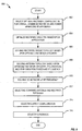
- FIG. 8 is a flowchart illustrating another exemplary process for designing a rectenna.
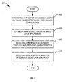
- FIG. 9 is a flowchart illustrating one exemplary process for designing a system for harvesting energy from power sources.
- FIG. 10 shows one exemplary block diagram of one exemplary rectenna and sensor system.
- FIG. 11 shows an exemplary model and a layout of a rectenna.
- FIG. 12 shows an exemplary graph illustrating simulated and measured output power of the rectenna of FIG. 11 as a function of output resistance, and an exemplary graph illustrating simulated and measured output voltage of the rectenna of FIG. 11 as a function of output resistance.
- FIG. 13 shows a block diagram illustrating one exemplary DC power processing circuit for obtaining plus and minus 15V power.
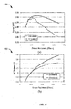
- FIG. 14 shows one exemplary graph illustrating measured DC output power of the circuit of FIG. 13 against polarization angle of radiation incident on the rectenna array and one exemplary graph illustrating DC output power and efficiency of the circuit of FIG. 13 against power received by the rectenna array
- FIG. 15 shows one exemplary circuit for a boost converter in variable frequency critical conduction mode (CRM).
- CRM variable frequency critical conduction mode
- FIG. 16 shows one exemplary circuit for a buck-boost converter in fixed frequency discontinuous conduction mode (DCM).
- DCM discontinuous conduction mode
- FIG. 17 shows two exemplary waveforms illustrating operation of the converter circuit of FIG. 15 .
- FIG. 18 shows one exemplary circuit for generating the gate driving signals for the circuit of FIG. 15 .
- FIG. 19 shows two exemplary equations that define operation of the circuit of FIG. 15 .
- FIG. 20 shows one exemplary two-stage adaptable switching-capacitor topology.
- FIG. 1 shows a power harvesting system 100 that includes power sources 102 and a controlled impedance, voltage or current power controller 104.
- Power harvesting system 100 is illustratively shown powering a powered device 106.
- Powered device 106 is, for example, a sensor and/or transceiver device.
- Power source 102 may represent one or more of: a rectenna, a photovoltaic cell, a piezoelectric device or other power collecting device.
- Power controller 104 is illustratively shown with energy storage 108, energy coupling 110 and energy management 112.
- Energy_storage 108 is for example a battery or a capacitor; it may be internal to power controller 104, as shown, or external to power controller 104 without departing from the scope hereof
- Energy management 112 instructs energy coupling 110 to convert energy received from power source 102 into a form suitable for storage by energy storage 108.
- energy coupling 110 may include a DC-to-DC voltage converter 116 that changes the DC voltage received from power source 102 such that it is suitable for storage in energy storage 108.
- the DC-to-DC voltage converter 116 may represent a step-up voltage converter or a step down voltage converter.
- DC-to-DC voltage converter 116 may include a plurality of different types of DC-to-DC voltage converters that are selectively chosen to convert DC electricity received from power source 102 into a form suitable for storage by energy storage 102.
- Energy coupling 110 is further shown with optional DC combining circuit 114, which operates to combine DC inputs from power source 102 where multiple power sources 102 provide power to controlled impedance power controller 104.
- DC combining circuit 114 may include one or more switches selected by energy management 112 to configure connectivity of multiple power sources 102.
- power source 102 is a rectenna array (e.g., rectenna array 200, FIG. 2 ) that has a plurality of antenna elements (e.g., antenna elements 202), depending on sensed characteristics of received power from the aperiodic rectenna
- energy management 112 may control DC coupling circuit 114 to configure antenna elements in series and/or parallel for optimum operation.
- energy management 112 may reconfigure connectivity of the rectenna array to improve energy harvesting efficiency.
- Energy management 112 may also receive information from powered device 106 via signal 118 that indicates power requirements of powered device 106. This information is used by energy management 112 to optimally configure energy coupling 110.
- power source 102 is represented by one or more rectennas. However, other power sources may also be used in place of the rectennas shown.
- FIG. 2 shows one exemplary periodic and uniform rectenna array 200, illustrating nine square patch antenna elements 202 on a grounded substrate 204.
- Each antenna element 202 has a rectifier 206, thereby forming a rectenna 208.
- Interconnectivity of periodic rectenna array 200 is not shown for clarity if illustration. Size and layout of each antenna element, connectivity of each rectifier thereto and substrate characteristics determine the frequency range and polarization of radio frequency waves received by rectenna array 200.
- Array 200 may be formed with alternate antenna designs without departing from the scope hereof.
- additional rectifiers may connect in parallel or series to rectifiers 206, also without departing from the scope hereof.
- FIG. 3 shows one exemplary aperiodic and non-uniform rectenna array 300 with five patch antenna elements 302 of a first size formed on a substrate 304, each antenna element 302 having a rectifier 306 to form a rectenna 312.
- Aperiodic rectenna array 300 also has a patch antenna element 308 of a second size formed on substrate 304; antenna element 308 has a rectifier 310 thus forming a rectenna 314.
- Rectenna 312 is designed for receiving radio frequency waves of a first frequency range
- rectenna 314 is designed for receiving radio frequency waves of a second frequency range.
- the aperiodic and non-uniform rectenna array 300 may receive radio frequency waves within both the first frequency range and the second frequency range.
- rectennas may be included within array 300. Size, layout and type of each antenna element, connectivity of each rectifier thereto determine the frequency range and polarization of radio frequency waves received by aperiodic non-unifonn rectenna array 300.
- connectivity of rectennas 208 within periodic rectenna array 200 and connectivity of rectennas 312 and 314 within aperiodic rectenna array 300 maybe based upon radio frequency waves incident at each rectenna array and the desired power output of the rectenna array.
- rectennas 208 may be connected in series or parallel.
- multiple periodic or aperiodic, uniform or non-uniform, rectenna arrays may be used to harvest RF energy.
- output from two periodic rectenna arrays, each having different sized antenna elements i.e., each receiving RF waves of different frequency ranges and/or polarizations
- a rectenna array (e.g., periodic rectenna array 200, FIG. 2 ) may also be reconfigured during operation. For example, if energy management 112 determines that output of rectenna array 200 is low, energy management 112 instructs energy coupling 110 to modify connectivity of rectenna array 200 (e.g., using DC combining circuit 114) to increase output voltage.
- DC combining circuit 114 for example contains switching components (e.g., MOSFETs, BJT, IGBT, relays, etc.) that allow dynamic configuration of connectivity to power source 102.
- energy management 112 may instruct energy coupling 110 to reconfigure antenna elements of rectenna array 200 into parallel and/or serial connectivity combinations, thereby reducing changing output voltage and current.
- Connectivity of one or more rectenna arrays is for example based upon one or more of output voltages, open circuit voltage, short circuit current, output current and output power of one or more antenna elements. Groups of antenna elements producing similar currents may be connected in serial, whereas groups of antenna elements producing similar voltages may be connected in parallel. Operating parameters of the power controller 104 may also be based upon one or more of output voltages, open circuit voltage, short circuit current, output current and output power of one or more antenna elements and / or, other power sources.
- Controlled impedance power controller 104 may include one or more sense circuits for monitoring characteristics of input power.
- the rectenna array may be designed such that RF power from two or more antenna elements are combined before rectification.
- FIGs. 15, 16 and 18 show exemplary circuits for presenting desired impedance to one or more power sources (e.g:, power source 102, FIG. 1 , periodic rectenna array 200, FIG. 2 , and aperiodic rectenna array 300, FIG. 3 ).
- power sources e.g:, power source 102, FIG. 1 , periodic rectenna array 200, FIG. 2 , and aperiodic rectenna array 300, FIG. 3 .
- Prior art DC-to-DC converters typically implement inverse resistive loading: as input power decreases, resistance presented to the input power source is reduced, thereby further loading the input source.
- Controlled impedance power controller 104 maintains resistance presented to the input source at a substantially constant level, even as input power levels vary.
- the controlled impedance may also be varied based on sensed conditions of the power source to emulate a desired impedance, input voltage or input current in order to improve the energy harvesting efficiency, for example by emulating a positive resistance load where resistance presented to the source increases as input power decreases.
- circuitry for power controller 104 depends on the desired application. Where high efficiency of energy harvesting is required, additional circuitry may be included to sense characteristics of the input power, whereas if the power source provides ample power, high efficiency may not be necessary, allowing simplified circuitry to be used.
- Alternative power sources may be combined for use with an RF power source 102.
- an RF wave rectenna array, a mechanical generator and a photovoltaic cell may be used as input to combining circuit 114 and power controller 104.
- Power controller 104 may then dynamically configure these inputs depending on sensed input characteristics and/or desired output requirements in order to improve energy harvesting efficiency.
- energy sources may be combined in such a way as to provide biasing to each other, thereby increasing overall energy harvesting efficiency.
- powered device 106 may provide feedback to energy management 112 to indicate its power needs. Energy management 112 may then configure power input connectivity as needed to provide the necessary power.
- Power controller 104 may also transfer energy from energy storage 108 to one or more power source 102 outputs in order to increase the overall energy harvesting efficiency. For example, energy can be transferred to the DC output of a rectenna for improved biasing, resulting in improved energy harvesting efficiency.
- DC-to-DC converter 116 may be selected from a plurality of converters to match the input power characteristics.
- FIG. 4 shows one exemplary energy coupling 402 that includes a plurality of DC-to-DC converters 404 and an optional DC combining circuit 406.
- DC combining circuit 406 may represent DC combining circuit 114, FIG. 1 .
- Energy coupling 402 may represent energy coupling 110, FIG. 1 .
- each of DC-to-DC converters 404 may represent one of: a four-switch buck-boost converter, a two-switch buck-boost converter, a boost converter operating in critical-conduction mode, a buck converter controlled to regulate input current or voltage as a function of the corresponding input voltage or current, and a switched capacitor converter.
- DC-to-DC converters 404 are selectable based upon input power characteristics and the type of storage device used for energy storage 108. As input power characteristics change, energy management 112 may select an alternate DC-to-DC converter as needed.
- energy management 112 may change the operating characteristics of DC to DC converter 116 to match the emulated input impedance of the converter to the desired load of the power source 102. For example, based upon one or more of: sensed open circuit voltage of power source 102, short circuit current of power source 102, operating voltage and current of power source 102, and output power of power source 102, characteristics of DC to DC converter 116 may be adjusted to emulate an appropriate resistance.
- FIG. 5 is a flowchart illustrating one process 500 for converting variable power DC electricity into usable DC electricity.
- Process 500 is for example performed by controller 104, FIG. 1 .
- process 500 senses characteristics of the variable low power DC electricity and then selects, in step 504, a DC-to-DC converter module and operating characteristics based upon the sensed characteristics, to convert the variable power DC electric into electricity suitable for storage.
- electricity suitable for storage is stored.
- the electricity may be stored in energy storage 108, FIG. 1 .
- the stored energy is then conditioned into the usable electricity.
- the energy from energy store 108 is conditioned and provided as DC electricity to powered device 106.
- FIG. 6 is a flowchart illustrating one process 600 for designing a system for harvesting energy from a power source.
- process 600 interacts with power source design software to select a power source configuration.
- process 600 solves the appropriate converter topology.
- process 600 selects the converter components and operating conditions.
- process 600 selects the appropriate control approach and settings.
- FIG. 7 is a flowchart illustrating one process 700 for designing a rectenna.
- process 700 selects the element size of the rectenna based upon available area, incident radiation power levels and operating frequency range.
- process 700 selects element polarization based upon the RF environment of operation.
- process 700 selects rectenna material based upon propagation medium and frequency range.
- process 700 selects a shape and size for the rectenna array based upon required output power levels, available power storage, operational duty cycles and available space.
- process 700 selects a radome appropriate for intended use.
- FIG. 8 is a flowchart illustrating another exemplary process 800 for designing a rectenna.
- process 800 uses power management design software to interactively select optimum rectenna configuration for overall combined rectenna and power management efficiency.
- process 800 optimizes the selected rectenna circuitry based upon application.
- process 800 solves rectifier circuit topology based upon optimized rectifier circuitry.
- process 800 solves antenna topology based upon optimized rectifier circuitry, polarization, incident radiation power level and frequency using full-wave electromagnetic simulations.
- process 800 solves the DC network at RF frequencies using a combination of full-wave electromagnetic and high-frequency circuit simulations.
- process 800 selects combined antenna and rectifier topology.
- process 800 selects appropriate rectenna array configuration.
- process 800 selects an appropriate package for integration with power manager based upon simulation of package for RF compatibility.
- FIG. 9 is a flowchart illustrating one process 900 for designing a system for harvesting energy from power sources.
- process 900 interacts with power source design software to select one or more desired power sources for overall combined power source and power manager efficiency.
- process 900 solves appropriate converter topology.
- process 900 selects converter components and operating conditions for maximum efficiency based upon selected power source configuration and output characteristics over designated incident power characteristics.
- process 900 selects an appropriate control approach and settings for maximum overall system efficiency over given system characteristics.
- FIG. 10 shows a block diagram of one exemplary rectenna and sensor system 1000.
- system 1000 has a rectenna array 1002, DC power processing 1004, sensor query electronics 1006, information processing 1008 and a piezoelectric sensor array 1010.
- system 1000 is used to sense structural failures from fatigue within an aircraft.
- Rectenna array 1002 is formed on a flexible substrate that may be conformed to a moderate curve of an aircraft.
- FIG. 11 shows an exemplary model 1100 and a layout 1150 of an ADS rectenna 1101.
- Model 1100 is shown with an antenna 1102, a diode 1104, an inductor 1106, a capacitor 1108 and a resistor 1110.
- a commercial lumped element capacitor 1158 representing capacitor 1108 and a small 0.24mm diameter wire 1156 representing inductor 1106 provide necessary impedance for an output filter of rectenna 1101.
- Output voltage of rectenna 1101 is measured across a variable resistor and the DC power is calculated as V 2 /R.
- FIG. 12 shows an exemplary graph 1200 illustrating simulated and measured output power of rectenna 1101 as a function of output resistance, and an exemplary graph 1250 illustrating simulated and measured output voltage of rectenna 1101 as a function of output resistance.
- FIG. 13 shows a block diagram illustrating one exemplary DC power processing circuit 1300 for obtaining plus and minus 15V power.
- Circuit 1300 is powered, for example, by an array of rectenna 1101, FIG. 11 , not shown.
- FIG. 14 shows one exemplary graph 1400 illustrating measured DC output power of circuit 1300 against polarization angle of incident radiation against the rectenna array and one exemplary graph 1450 illustrating DC output power and efficiency of circuit 1300 against received power by the rectenna array.
- FIG. 15 shows one exemplary circuit 1500 for a boost converter in variable frequency critical conduction mode (CRM).
- FIG. 16 shows one exemplary circuit 1600 for a buck-boost converter in fixed frequency discontinuous conduction mode (DCM). Note that in both circuits 1500 and 1600, a two-switch implementation is possible due to the floating input power source.
- the converter circuits 1500, 1600 may be operated continuously at higher input power levels, or operated in a pulsed mode at lower power levels, as shown in waveforms 1700 and 1750 of FIG. 17 .
- waveform 1700 of FIG. 17 shows inductor current under steady-state operation of circuit 1500, FIG. 15 .
- transistor Q 1 is turned on and Q 2 is turned off during t on , and thus the inductor current ramps up from zero to i pk over that time.
- Q 1 is turned off, and Q 2 is turned on to move the energy to the load.
- This second transition lasts until the inductor current drops to zero.
- the first transition is repeated.
- the converter of circuit 1500 runs in this mode for a certain duty cycle, k, of a low frequency period, T lf . At kT lf , the converter turns off and starts up again at T lf .
- the emulated input resistance seen by the source is changed. Changing the emulated input resistance to match the optimum rectenna load maximizes energy harvesting.
- the input voltage source is shown as Vg, and the output energy is stored in an energy storage element such as a capacitor or micro-battery.
- the voltage, V zcrs is a sense point used by a comparator to find a zero crossing of the inductor current.
- the open circuit voltage, V oc , or a short circuit current, I sc may be used by additional control circuitry to find the operating input power level and set k.
- the gate driving signals, gate n and gate p are essentially the same signal when the converter is operating in critical conduction mode. However, both drive their respective MOSFETs off after kT lf ; thus gate n is a low voltage signal and gate p is a high voltage signal.
- C 1 and C 2 are input and output filter capacitors.
- Diode Q 2 may be used to precharge the energy storage element, thus enabling start-up from zero energy.
- the control circuitry for this boost converter generates the gate driving signals, given the zero crossing point of the inductor current and the parameters: t on , T lf ., and k. This is for example achieved with the exemplary circuit 1800 shown in FIG. 18 .
- V zcrs The voltage, V zcrs , from the power stage is the positive input into a comparator with the negative input tied to ground. V zcrs is a negative voltage most of the time. Detection of a zero-crossing by the comparator triggers a pulse, from a one-shot circuit, with width t on . This pulse is passed through two OR-gates and then to circuit 1500 as gate n and gate p . A second input into the gate p OR-gate is a signal from a low frequency oscillator that is logic high after kT lf . This ensures that both Q 1 and Q 2 are off after that point. The low frequency oscillator operating at period, T lf , also provides the same signal to power off the comparator and one-shot circuitry when the converter is not in operation for reduced control power loss and to power them back on afterwards.
- Prior art power converters for very low power levels have low efficiency due to parasitic leakage currents and parasitic capacitance to the substrate. These limitations are removed by developing a set of integrated converters for high efficiency energy harvesting using an RF process. This process is based on fully-depleted silicon-on-insulator (FD-SOI) with a thick upper metal layer for inductors and a high resistivity substrate.
- FD-SOI fully-depleted silicon-on-insulator
- the primary advantages in this process for power processing are reduced parasitic capacitances, which are up to 1000 times lower than in a traditional CMOS silicon process. Such low parasitics facilitate high efficiency operation, even at very low power levels and frequencies as high as hundreds of kHz (allowing small component sizes).
- An integrated power converter IC maybe be constructed with single and two-stage switched capacitor (SC) circuits, which have high efficiency at very low power levels since parasitic capacitance is small.
- SC switched capacitor
- FIG. 20 shows one exemplary two-stage SC topology 2000.
- On-chip buffers may be provided for each of the switches (S 1 -S 11 ) and external control logic (e.g., controller 2002) may be used to determine the switching configuration.
- Topology 2000 generates eight distinct power conversion ratios from the input voltage (V in ) to the output voltage (V out ) for ratios from one third to three.
- the external control chip adaptively adjusts the switching frequency and topology to continuously extract maximum power from attached rectennas while storing the harvested energy to the output capacitor (C storage ). As the output capacitor voltage builds, the converter sequences through topologies to maintain optimal loading of the rectenna and high efficiency.
Landscapes
- Engineering & Computer Science (AREA)
- Physics & Mathematics (AREA)
- Electromagnetism (AREA)
- Computer Networks & Wireless Communication (AREA)
- Power Engineering (AREA)
- Dc-Dc Converters (AREA)
- Charge And Discharge Circuits For Batteries Or The Like (AREA)
- Direct Current Feeding And Distribution (AREA)
Description
- This application claims priority to
US Provisional Patent Application Serial Number 60/729,378 filed October 21, 2005US Provisional Patent Application Serial Number 60/760,040, filed January 17, 2006 - Sensors and transmitters that are small and require low levels of power for operation are frequently used for collecting information without being intrusive to their operating environment. For example, a battery powered sensing and transmitting device may be surgically implanted within living tissue to sense and transmit characteristics of the body in which it is implanted.
- The lifetime of the battery used within such a sensor often requires additional surgical procedures to periodically replace the battery. Similarly, where a sensor and transmitting device is located within controlled or hazardous environments, it is often a time-consuming and expensive task to periodically replace the battery.
- Energy may be harvested from radio frequency ("RF") waves for use in remote sensors and transmitting devices. One example of this functionality is an RF identification ("RFID") tag that derives power from an RF wave (e.g., from a transmitting device operating to read the RFID tag) and uses that power to transmit an identification signal. One drawback of this technology is that the RFID tags typically only operate over short distances.
- A rectenna is an antenna that includes a rectifier; the rectenna receives RF waves, rectifies the waves and produces direct current ("DC") electricity. The DC electricity produced by the rectenna is dependent on rectenna design, RF wave frequency, RF wave polarization and RF wave power level incident at the rectenna. Typically, the DC electricity output from the rectenna is conditioned by conditioning electronics before being fed to a powered device (e.g., sensor, microprocessor, transmitter etc.). Where characteristics of the RF wave vary, the DC electricity output from the rectenna also varies; this affects power conversion efficiency due to loading upon the rectenna by the conditioning electronics which attempts to maintain a constant power output for the powered device.
-
US5068669 discloses a system and method for power beaming energy from a source at high frequencies and rectifying such energy to provide a source of DC energy is disclosed. The system operates at a frequency of at least 10 GHz and incorporates a rectenna array having a plurality of rectenna structures that utilize circuit elements formed with microstrip circuit techniques. -
US5719586 introduces an RFID system that comprises a two-dimensional antenna configuration having a dipole in combination with a loop antenna or a second dipole with their dipole axes at approximately a 90 DEG angle to one another. The pattern of two dipole antennas combined with the pattern of a single loop antenna, allows the sequential combination of the patterns to represent a nearly spherical antenna pattern in three dimensions, while the antennas reside in a two-dimensional plane. - Accordingly the present application provides a reconfigurable radio frequency (RF) reception device in accordance with the claims which follow.
-
FIG. 1 shows a power harvesting system that includes power sources and a controlled impedance, voltage or current power controller. -
FIG. 2 shows one exemplary periodic and uniform rectenna array. -
FIG. 3 shows one exemplary aperiodic and non-uniform rectenna array. -
FIG. 4 illustrates exemplary energy coupling including a plurality of DC-to-DC converters. -
FIG. 5 is a flowchart illustrating one exemplary process for converting variable power DC electricity into usable DC electricity. -
FIG. 6 is a flowchart illustrating one process for designing a system for harvesting energy from a power source. -
FIG. 7 is a flowchart illustrating one process for designing a rectenna. -
FIG. 8 is a flowchart illustrating another exemplary process for designing a rectenna. -
FIG. 9 is a flowchart illustrating one exemplary process for designing a system for harvesting energy from power sources. -
FIG. 10 shows one exemplary block diagram of one exemplary rectenna and sensor system. -
FIG. 11 shows an exemplary model and a layout of a rectenna. -
FIG. 12 shows an exemplary graph illustrating simulated and measured output power of the rectenna ofFIG. 11 as a function of output resistance, and an exemplary graph illustrating simulated and measured output voltage of the rectenna ofFIG. 11 as a function of output resistance. -
FIG. 13 shows a block diagram illustrating one exemplary DC power processing circuit for obtaining plus andminus 15V power. -
FIG. 14 shows one exemplary graph illustrating measured DC output power of the circuit ofFIG. 13 against polarization angle of radiation incident on the rectenna array and one exemplary graph illustrating DC output power and efficiency of the circuit ofFIG. 13 against power received by the rectenna array -
FIG. 15 shows one exemplary circuit for a boost converter in variable frequency critical conduction mode (CRM). -
FIG. 16 shows one exemplary circuit for a buck-boost converter in fixed frequency discontinuous conduction mode (DCM). -
FIG. 17 shows two exemplary waveforms illustrating operation of the converter circuit ofFIG. 15 . -
FIG. 18 shows one exemplary circuit for generating the gate driving signals for the circuit ofFIG. 15 . -
FIG. 19 shows two exemplary equations that define operation of the circuit ofFIG. 15 . -
FIG. 20 shows one exemplary two-stage adaptable switching-capacitor topology. -
FIG. 1 shows apower harvesting system 100 that includespower sources 102 and a controlled impedance, voltage orcurrent power controller 104.Power harvesting system 100 is illustratively shown powering a powereddevice 106. Powereddevice 106 is, for example, a sensor and/or transceiver device.Power source 102 may represent one or more of: a rectenna, a photovoltaic cell, a piezoelectric device or other power collecting device. -
Power controller 104 is illustratively shown with energy storage 108,energy coupling 110 andenergy management 112. Energy_storage 108 is for example a battery or a capacitor; it may be internal topower controller 104, as shown, or external topower controller 104 without departing from the scope hereof -
Energy management 112 instructsenergy coupling 110 to convert energy received frompower source 102 into a form suitable for storage by energy storage 108. Accordingly,energy coupling 110 may include a DC-to-DC voltage converter 116 that changes the DC voltage received frompower source 102 such that it is suitable for storage in energy storage 108. The DC-to-DC voltage converter 116 may represent a step-up voltage converter or a step down voltage converter. Or, DC-to-DC voltage converter 116 may include a plurality of different types of DC-to-DC voltage converters that are selectively chosen to convert DC electricity received frompower source 102 into a form suitable for storage byenergy storage 102. -
Energy coupling 110 is further shown with optionalDC combining circuit 114, which operates to combine DC inputs frompower source 102 wheremultiple power sources 102 provide power to controlledimpedance power controller 104.DC combining circuit 114 may include one or more switches selected byenergy management 112 to configure connectivity ofmultiple power sources 102. For example, wherepower source 102 is a rectenna array (e.g., rectennaarray 200,FIG. 2 ) that has a plurality of antenna elements (e.g., antenna elements 202), depending on sensed characteristics of received power from the aperiodic rectenna,energy management 112 may controlDC coupling circuit 114 to configure antenna elements in series and/or parallel for optimum operation. In particular, as power levels, frequencies and polarizations of incident RF waves change,energy management 112 may reconfigure connectivity of the rectenna array to improve energy harvesting efficiency. -
Energy management 112 may also receive information from powereddevice 106 viasignal 118 that indicates power requirements of powereddevice 106. This information is used byenergy management 112 to optimally configureenergy coupling 110. - In the following examples,
power source 102 is represented by one or more rectennas. However, other power sources may also be used in place of the rectennas shown. -
FIG. 2 shows one exemplary periodic and uniformrectenna array 200, illustrating nine squarepatch antenna elements 202 on agrounded substrate 204. Eachantenna element 202 has arectifier 206, thereby forming arectenna 208. Interconnectivity ofperiodic rectenna array 200 is not shown for clarity if illustration. Size and layout of each antenna element, connectivity of each rectifier thereto and substrate characteristics determine the frequency range and polarization of radio frequency waves received byrectenna array 200. -
Array 200 may be formed with alternate antenna designs without departing from the scope hereof. Moreover, additional rectifiers may connect in parallel or series torectifiers 206, also without departing from the scope hereof. -
FIG. 3 shows one exemplary aperiodic andnon-uniform rectenna array 300 with fivepatch antenna elements 302 of a first size formed on asubstrate 304, eachantenna element 302 having arectifier 306 to form arectenna 312.Aperiodic rectenna array 300 also has apatch antenna element 308 of a second size formed onsubstrate 304;antenna element 308 has arectifier 310 thus forming arectenna 314.Rectenna 312 is designed for receiving radio frequency waves of a first frequency range, and rectenna 314 is designed for receiving radio frequency waves of a second frequency range. Thus, the aperiodic andnon-uniform rectenna array 300 may receive radio frequency waves within both the first frequency range and the second frequency range. - Additional or different rectennas may be included within
array 300. Size, layout and type of each antenna element, connectivity of each rectifier thereto determine the frequency range and polarization of radio frequency waves received by aperiodicnon-unifonn rectenna array 300. - Although not shown in
FIGs. 2 and3 , connectivity ofrectennas 208 withinperiodic rectenna array 200 and connectivity ofrectennas aperiodic rectenna array 300 maybe based upon radio frequency waves incident at each rectenna array and the desired power output of the rectenna array. For example, rectennas 208 may be connected in series or parallel. - Selection of a suitable rectifier topology and rectification device, based upon frequency range and power levels received, is also important for efficient operation of these rectenna arrays.
- Multiple periodic or aperiodic, uniform or non-uniform, rectenna arrays may be used to harvest RF energy. For example, output from two periodic rectenna arrays, each having different sized antenna elements (i.e., each receiving RF waves of different frequency ranges and/or polarizations) may be combined for conditioning by controlled impedance (or DC input parameter)
power controller 104,FIG. 1 . - A rectenna array (e.g.,
periodic rectenna array 200,FIG. 2 ) may also be reconfigured during operation. For example, ifenergy management 112 determines that output ofrectenna array 200 is low,energy management 112 instructsenergy coupling 110 to modify connectivity of rectenna array 200 (e.g., using DC combining circuit 114) to increase output voltage.DC combining circuit 114 for example contains switching components (e.g., MOSFETs, BJT, IGBT, relays, etc.) that allow dynamic configuration of connectivity topower source 102. - If
energy management 112 determines that output power of the rectenna array is high,energy management 112 may instructenergy coupling 110 to reconfigure antenna elements ofrectenna array 200 into parallel and/or serial connectivity combinations, thereby reducing changing output voltage and current. - Connectivity of one or more rectenna arrays is for example based upon one or more of output voltages, open circuit voltage, short circuit current, output current and output power of one or more antenna elements. Groups of antenna elements producing similar currents may be connected in serial, whereas groups of antenna elements producing similar voltages may be connected in parallel. Operating parameters of the
power controller 104 may also be based upon one or more of output voltages, open circuit voltage, short circuit current, output current and output power of one or more antenna elements and / or, other power sources. - Controlled
impedance power controller 104 may include one or more sense circuits for monitoring characteristics of input power. - The rectenna array may be designed such that RF power from two or more antenna elements are combined before rectification.
-
FIGs. 15, 16 and18 , described below, show exemplary circuits for presenting desired impedance to one or more power sources (e.g:,power source 102,FIG. 1 ,periodic rectenna array 200,FIG. 2 , andaperiodic rectenna array 300,FIG. 3 ). Prior art DC-to-DC converters typically implement inverse resistive loading: as input power decreases, resistance presented to the input power source is reduced, thereby further loading the input source. Controlledimpedance power controller 104, on the other hand, maintains resistance presented to the input source at a substantially constant level, even as input power levels vary. The controlled impedance may also be varied based on sensed conditions of the power source to emulate a desired impedance, input voltage or input current in order to improve the energy harvesting efficiency, for example by emulating a positive resistance load where resistance presented to the source increases as input power decreases. - Selection of circuitry for
power controller 104 depends on the desired application. Where high efficiency of energy harvesting is required, additional circuitry may be included to sense characteristics of the input power, whereas if the power source provides ample power, high efficiency may not be necessary, allowing simplified circuitry to be used. - Alternative power sources may be combined for use with an
RF power source 102. For example, an RF wave rectenna array, a mechanical generator and a photovoltaic cell may be used as input to combiningcircuit 114 andpower controller 104.Power controller 104 may then dynamically configure these inputs depending on sensed input characteristics and/or desired output requirements in order to improve energy harvesting efficiency. In particular, energy sources may be combined in such a way as to provide biasing to each other, thereby increasing overall energy harvesting efficiency. Optionally,powered device 106 may provide feedback toenergy management 112 to indicate its power needs.Energy management 112 may then configure power input connectivity as needed to provide the necessary power. -
Power controller 104 may also transfer energy from energy storage 108 to one ormore power source 102 outputs in order to increase the overall energy harvesting efficiency. For example, energy can be transferred to the DC output of a rectenna for improved biasing, resulting in improved energy harvesting efficiency. - Where input power conditions vary, DC-to-
DC converter 116 may be selected from a plurality of converters to match the input power characteristics.FIG. 4 shows oneexemplary energy coupling 402 that includes a plurality of DC-to-DC converters 404 and an optionalDC combining circuit 406.DC combining circuit 406 may representDC combining circuit 114,FIG. 1 .Energy coupling 402 may representenergy coupling 110,FIG. 1 . For example, each of DC-to-DC converters 404 may represent one of: a four-switch buck-boost converter, a two-switch buck-boost converter, a boost converter operating in critical-conduction mode, a buck converter controlled to regulate input current or voltage as a function of the corresponding input voltage or current, and a switched capacitor converter. DC-to-DC converters 404 are selectable based upon input power characteristics and the type of storage device used for energy storage 108. As input power characteristics change,energy management 112 may select an alternate DC-to-DC converter as needed. - Where input power conditions vary,
energy management 112 may change the operating characteristics of DC toDC converter 116 to match the emulated input impedance of the converter to the desired load of thepower source 102. For example, based upon one or more of: sensed open circuit voltage ofpower source 102, short circuit current ofpower source 102, operating voltage and current ofpower source 102, and output power ofpower source 102, characteristics of DC toDC converter 116 may be adjusted to emulate an appropriate resistance. -
FIG. 5 is a flowchart illustrating oneprocess 500 for converting variable power DC electricity into usable DC electricity.Process 500 is for example performed bycontroller 104,FIG. 1 . Instep 502,process 500 senses characteristics of the variable low power DC electricity and then selects, instep 504, a DC-to-DC converter module and operating characteristics based upon the sensed characteristics, to convert the variable power DC electric into electricity suitable for storage. Instep 506, electricity suitable for storage is stored. For example, the electricity may be stored in energy storage 108,FIG. 1 . The stored energy is then conditioned into the usable electricity. For example, the energy from energy store 108 is conditioned and provided as DC electricity topowered device 106. -
FIG. 6 is a flowchart illustrating oneprocess 600 for designing a system for harvesting energy from a power source. Instep 602,process 600 interacts with power source design software to select a power source configuration. Instep 604,process 600 solves the appropriate converter topology. Instep 606,process 600 selects the converter components and operating conditions. Instep 608,process 600 selects the appropriate control approach and settings. -
FIG. 7 is a flowchart illustrating oneprocess 700 for designing a rectenna. Instep 702,process 700 selects the element size of the rectenna based upon available area, incident radiation power levels and operating frequency range. Instep 704,process 700 selects element polarization based upon the RF environment of operation. Instep 706,process 700 selects rectenna material based upon propagation medium and frequency range. Instep 708,process 700 selects a shape and size for the rectenna array based upon required output power levels, available power storage, operational duty cycles and available space. Instep 710,process 700 selects a radome appropriate for intended use. -
FIG. 8 is a flowchart illustrating anotherexemplary process 800 for designing a rectenna. Instep 802,process 800 uses power management design software to interactively select optimum rectenna configuration for overall combined rectenna and power management efficiency. Instep 804,process 800 optimizes the selected rectenna circuitry based upon application. Instep 806,process 800 solves rectifier circuit topology based upon optimized rectifier circuitry. Instep 808,process 800 solves antenna topology based upon optimized rectifier circuitry, polarization, incident radiation power level and frequency using full-wave electromagnetic simulations. Instep 810,process 800 solves the DC network at RF frequencies using a combination of full-wave electromagnetic and high-frequency circuit simulations. Instep 812,process 800 selects combined antenna and rectifier topology. Instep 814,process 800 selects appropriate rectenna array configuration. Instep 816,process 800 selects an appropriate package for integration with power manager based upon simulation of package for RF compatibility. -
FIG. 9 is a flowchart illustrating oneprocess 900 for designing a system for harvesting energy from power sources. Instep 902,process 900 interacts with power source design software to select one or more desired power sources for overall combined power source and power manager efficiency. Instep 904,process 900 solves appropriate converter topology. Instep 906,process 900 selects converter components and operating conditions for maximum efficiency based upon selected power source configuration and output characteristics over designated incident power characteristics. Instep 908,process 900 selects an appropriate control approach and settings for maximum overall system efficiency over given system characteristics. -
FIG. 10 shows a block diagram of one exemplary rectenna andsensor system 1000. In particular,system 1000 has arectenna array 1002,DC power processing 1004,sensor query electronics 1006,information processing 1008 and apiezoelectric sensor array 1010. In one example,system 1000 is used to sense structural failures from fatigue within an aircraft.Rectenna array 1002 is formed on a flexible substrate that may be conformed to a moderate curve of an aircraft. -
FIG. 11 shows anexemplary model 1100 and alayout 1150 of an ADS rectenna 1101.Model 1100 is shown with anantenna 1102, adiode 1104, aninductor 1106, acapacitor 1108 and aresistor 1110. As shown inlayout 1150, a commercial lumpedelement capacitor 1158 representingcapacitor 1108 and a small 0.24mm diameter wire 1156 representinginductor 1106 provide necessary impedance for an output filter of rectenna 1101. Output voltage of rectenna 1101 is measured across a variable resistor and the DC power is calculated as V2/R. -
FIG. 12 shows anexemplary graph 1200 illustrating simulated and measured output power of rectenna 1101 as a function of output resistance, and anexemplary graph 1250 illustrating simulated and measured output voltage of rectenna 1101 as a function of output resistance. -
FIG. 13 shows a block diagram illustrating one exemplary DCpower processing circuit 1300 for obtaining plus and minus 15V power.Circuit 1300 is powered, for example, by an array of rectenna 1101,FIG. 11 , not shown. -
FIG. 14 shows oneexemplary graph 1400 illustrating measured DC output power ofcircuit 1300 against polarization angle of incident radiation against the rectenna array and oneexemplary graph 1450 illustrating DC output power and efficiency ofcircuit 1300 against received power by the rectenna array. -
FIG. 15 shows oneexemplary circuit 1500 for a boost converter in variable frequency critical conduction mode (CRM).FIG. 16 shows oneexemplary circuit 1600 for a buck-boost converter in fixed frequency discontinuous conduction mode (DCM). Note that in bothcircuits converter circuits waveforms FIG. 17 . - In particular,
waveform 1700 ofFIG. 17 shows inductor current under steady-state operation ofcircuit 1500,FIG. 15 . In a first transition ofcircuit 1500, transistor Q1 is turned on and Q2 is turned off during ton, and thus the inductor current ramps up from zero to ipk over that time. After this transition, Q1 is turned off, and Q2 is turned on to move the energy to the load. This second transition lasts until the inductor current drops to zero. When this occurs, the first transition is repeated. The converter ofcircuit 1500 runs in this mode for a certain duty cycle, k, of a low frequency period, Tlf. At kTlf, the converter turns off and starts up again at Tlf. By adjusting k or ton, the emulated input resistance seen by the source is changed. Changing the emulated input resistance to match the optimum rectenna load maximizes energy harvesting. - In
circuit 1500, the input voltage source is shown as Vg, and the output energy is stored in an energy storage element such as a capacitor or micro-battery. The voltage, Vzcrs, is a sense point used by a comparator to find a zero crossing of the inductor current. Optionally, the open circuit voltage, Voc, or a short circuit current, Isc, may be used by additional control circuitry to find the operating input power level and set k. The gate driving signals, gaten and gatep, are essentially the same signal when the converter is operating in critical conduction mode. However, both drive their respective MOSFETs off after kTlf; thus gaten is a low voltage signal and gatep is a high voltage signal. C1 and C2 are input and output filter capacitors. Diode Q2 may be used to precharge the energy storage element, thus enabling start-up from zero energy. The control circuitry for this boost converter generates the gate driving signals, given the zero crossing point of the inductor current and the parameters: ton, Tlf., and k. This is for example achieved with theexemplary circuit 1800 shown inFIG. 18 . - The voltage, Vzcrs, from the power stage is the positive input into a comparator with the negative input tied to ground. Vzcrs is a negative voltage most of the time. Detection of a zero-crossing by the comparator triggers a pulse, from a one-shot circuit, with width ton. This pulse is passed through two OR-gates and then to
circuit 1500 as gaten and gatep. A second input into the gatep OR-gate is a signal from a low frequency oscillator that is logic high after kTlf. This ensures that both Q1 and Q2 are off after that point. The low frequency oscillator operating at period, Tlf, also provides the same signal to power off the comparator and one-shot circuitry when the converter is not in operation for reduced control power loss and to power them back on afterwards. - As can be seen from
equation 1950,FIG. 19 , if the boost converter operates continuously, the emulated resistance Remulated is only be dependent on ton since k = 1. This simplifies the control circuitry since only the zero crossing detecting comparator and the one-shot are used. However, these circuits are on continuously, even at low input power. Implementation of the low frequency duty cycle control method allows some of the circuitry to be powered off at times, depending on the input power level. Note that peak power tracking components in the control sample the open circuit voltage, Voc, of the input source when the converter is not in operation. These components may also sample the short circuit current, Isc. These values maybe used to adjust k or ton and thus change Remulated to be the optimum impedance load. If operation at lower power levels is desired, these additional control blocks may be implemented. - Prior art power converters for very low power levels have low efficiency due to parasitic leakage currents and parasitic capacitance to the substrate. These limitations are removed by developing a set of integrated converters for high efficiency energy harvesting using an RF process. This process is based on fully-depleted silicon-on-insulator (FD-SOI) with a thick upper metal layer for inductors and a high resistivity substrate. The primary advantages in this process for power processing are reduced parasitic capacitances, which are up to 1000 times lower than in a traditional CMOS silicon process. Such low parasitics facilitate high efficiency operation, even at very low power levels and frequencies as high as hundreds of kHz (allowing small component sizes). An integrated power converter IC maybe be constructed with single and two-stage switched capacitor (SC) circuits, which have high efficiency at very low power levels since parasitic capacitance is small.
-
FIG. 20 shows one exemplary two-stage SC topology 2000. On-chip buffers may be provided for each of the switches (S1-S11) and external control logic (e.g., controller 2002) may be used to determine the switching configuration.Topology 2000 generates eight distinct power conversion ratios from the input voltage (Vin) to the output voltage (Vout) for ratios from one third to three. The external control chip adaptively adjusts the switching frequency and topology to continuously extract maximum power from attached rectennas while storing the harvested energy to the output capacitor (Cstorage). As the output capacitor voltage builds, the converter sequences through topologies to maintain optimal loading of the rectenna and high efficiency. - Changes may be made in the above methods and systems without departing from the scope hereof. It should thus be noted that the matter contained in the above description or shown in the accompanying drawings should be interpreted as illustrative and not in a limiting sense.
Claims (14)
- A radio frequency (RF) reception device (100), comprising:a plurality of antenna elements arranged in an array (300), each of the antenna elements (302;308) having at least one rectifier (306;310) integrated therewith to form a rectenna element (312;314), wherein the radio frequency (RF) reception device is reconfigurable, electrical conductors providing connectivity to each of the plurality of antenna elements and rectifiers and wherein selective reception of RF energy by the plurality of antenna elements is determined by size, shape, layout and substrate characteristics of the plurality of antenna elements, the device further comprising a power controller (104) adapted to reconfigure the coupling of the rectenna elements(312;314) into parallel and/or serial connectivity combinations when it determines the output power of the array is too high or too low, characterised in that a first set of antenna elements (302) selected from the plurality of antenna elements has a first size and wherein a second set (308) of antenna elements selected from the plurality of antenna elements has a second size wherein the first and second sizes are different.
- The RF device of claim 1, wherein feed points of the first and second sets of antenna elements (302;308) defines polarization of the RF energy received.
- The RF device of claim 2, wherein shape, size, spacing, substrate characteristics and ground plane proximity of the first and second sets of antenna elements (302;308) defines the frequency range of the RF energy received.
- The RF reception device of claim 1 , wherein the antenna array (300) has three or more antenna elements with uniform spacing.
- The RF reception device of claim 1, wherein the antenna array (300) has three or more antenna elements with non-uniform spacing.
- The RF reception device of claim 1, wherein the antenna array (300) is configured to receive multiple polarizations.
- The RF reception device of claim 1, wherein the first periodic or aperiodic antenna array is configured to receive multiple frequencies.
- The RF reception device of claim 1, wherein feed points of each of the antenna elements are selected based upon desired polarization for each of the antenna elements.
- The RF reception device of claim 1, wherein feed points of each of the antenna elements are selected based upon desired impedance of each of the antenna elements, the impedance selected to match rectifier impedance.
- The RF reception device of claim 1, further comprising an enclosure for containing the antenna array, rectifiers and electrical conductors to allow use in biomedical implants.
- A system for collecting and conditioning variable DC electrical power, the system comprising the RF reception device of any preceding claim (100) and further comprising: conditioning electronics for converting the variable DC electrical power to storable DC electricity, the conditioning electronics (116) presenting a desired impedance to the at least one source; and a storage device (108) for storing the storable DC electricity.
- The system of claim 11, wherein the storage device (108) is a capacitor and the conditioning electronics vary the voltage of the storable DC electricity based upon accumulated electricity within the capacitor.
- The system of claim 11, wherein the storage device (108) is a battery and the conditioning electronics maintain the voltage of the storable DC electricity.
- The system of claim 11, wherein the conditioning electronics (116) comprise a first type of DC to DC converter selected from the group of: a four-switch buck- boost converter, a two-switch buck-boost converter, a boost converter operating in critical-conduction mode, a buck converter controlled to regulate input current proportional to input voltage, and a switched capacitor converter.
Applications Claiming Priority (3)
| Application Number | Priority Date | Filing Date | Title |
|---|---|---|---|
| US72937805P | 2005-10-21 | 2005-10-21 | |
| US76004006P | 2006-01-17 | 2006-01-17 | |
| PCT/US2006/041355 WO2007048052A2 (en) | 2005-10-21 | 2006-10-23 | Systems and methods for receiving and managing power in wireless devices |
Publications (2)
| Publication Number | Publication Date |
|---|---|
| EP1949309A2 EP1949309A2 (en) | 2008-07-30 |
| EP1949309B1 true EP1949309B1 (en) | 2014-01-15 |
Family
ID=37728301
Family Applications (1)
| Application Number | Title | Priority Date | Filing Date |
|---|---|---|---|
| EP20060826504 Not-in-force EP1949309B1 (en) | 2005-10-21 | 2006-10-23 | Systems and methods for receiving and managing power in wireless devices |
Country Status (9)
| Country | Link |
|---|---|
| US (1) | US7956572B2 (en) |
| EP (1) | EP1949309B1 (en) |
| JP (1) | JP2009513098A (en) |
| KR (1) | KR20080064986A (en) |
| CN (1) | CN101331503B (en) |
| AU (1) | AU2006304861A1 (en) |
| CA (1) | CA2626345A1 (en) |
| SG (1) | SG180030A1 (en) |
| WO (1) | WO2007048052A2 (en) |
Families Citing this family (344)
| Publication number | Priority date | Publication date | Assignee | Title |
|---|---|---|---|---|
| US7557433B2 (en) | 2004-10-25 | 2009-07-07 | Mccain Joseph H | Microelectronic device with integrated energy source |
| EP1891741A4 (en) | 2005-06-08 | 2011-08-24 | Powercast Corp | ELECTRIC POWER SUPPLY OF A RADIO FREQUENCY ENERGY COLLECTION DEVICE |
| US9130602B2 (en) | 2006-01-18 | 2015-09-08 | Qualcomm Incorporated | Method and apparatus for delivering energy to an electrical or electronic device via a wireless link |
| US8013474B2 (en) * | 2006-11-27 | 2011-09-06 | Xslent Energy Technologies, Llc | System and apparatuses with multiple power extractors coupled to different power sources |
| US7839025B2 (en) * | 2006-11-27 | 2010-11-23 | Xslent Energy Technologies, Llc | Power extractor detecting a power change |
| US7960870B2 (en) * | 2006-11-27 | 2011-06-14 | Xslent Energy Technologies, Llc | Power extractor for impedance matching |
| US9431828B2 (en) | 2006-11-27 | 2016-08-30 | Xslent Energy Technologies | Multi-source, multi-load systems with a power extractor |
| CN101657916A (en) | 2007-02-09 | 2010-02-24 | 西姆贝特公司 | Charging systems and methods |
| US9774086B2 (en) | 2007-03-02 | 2017-09-26 | Qualcomm Incorporated | Wireless power apparatus and methods |
| US9124120B2 (en) | 2007-06-11 | 2015-09-01 | Qualcomm Incorporated | Wireless power system and proximity effects |
| JP5455174B2 (en) * | 2007-08-02 | 2014-03-26 | 鹿島建設株式会社 | Wireless power receiving adapter |
| JP5697979B2 (en) * | 2007-08-09 | 2015-04-08 | クゥアルコム・インコーポレイテッドQualcomm Incorporated | System and method for wireless powering and charging |
| US8416721B1 (en) | 2007-09-19 | 2013-04-09 | Marcellus Chen | Method and apparatus for enhancing the power efficiency of wireless communication devices |
| US20090117872A1 (en) * | 2007-11-05 | 2009-05-07 | Jorgenson Joel A | Passively powered element with multiple energy harvesting and communication channels |
| JP5364270B2 (en) * | 2008-01-22 | 2013-12-11 | 株式会社東芝 | Charger |
| US8212541B2 (en) * | 2008-05-08 | 2012-07-03 | Massachusetts Institute Of Technology | Power converter with capacitive energy transfer and fast dynamic response |
| US9634577B2 (en) | 2008-11-11 | 2017-04-25 | Massachusetts Institute Of Technology | Inverter/power amplifier with capacitive energy transfer and related techniques |
| EP2353219B1 (en) | 2008-11-11 | 2018-05-02 | Massachusetts Institute of Technology | An asymmetric multilevel outphasing architecture for rf amplifiers |
| US20110101789A1 (en) * | 2008-12-01 | 2011-05-05 | Salter Jr Thomas Steven | Rf power harvesting circuit |
| WO2010075897A1 (en) * | 2008-12-30 | 2010-07-08 | Telecom Italia S.P.A. | A radio coverage extender for a personal area network node embedded in a user communications terminal |
| US20100181964A1 (en) * | 2009-01-22 | 2010-07-22 | Mark Huggins | Wireless power distribution system and method for power tools |
| US9257865B2 (en) | 2009-01-22 | 2016-02-09 | Techtronic Power Tools Technology Limited | Wireless power distribution system and method |
| US8338991B2 (en) * | 2009-03-20 | 2012-12-25 | Qualcomm Incorporated | Adaptive impedance tuning in wireless power transmission |
| KR20100118383A (en) * | 2009-04-28 | 2010-11-05 | 한국전자통신연구원 | Apparatus for harvesting energy from a microwave |
| KR101344024B1 (en) * | 2009-06-18 | 2013-12-24 | 한국전자통신연구원 | Maximum power tracking device using orthogonal perturbation signal and maximum power tracking control method thereof |
| EP2497180A1 (en) * | 2009-11-04 | 2012-09-12 | Triune IP LLC | Bootstrapped charger |
| US20110115605A1 (en) * | 2009-11-17 | 2011-05-19 | Strattec Security Corporation | Energy harvesting system |
| JP5419650B2 (en) | 2009-11-26 | 2014-02-19 | 三菱重工業株式会社 | Power receiving apparatus and wireless power transmission system |
| KR101040544B1 (en) | 2009-12-03 | 2011-06-16 | 주식회사 파이칩스 | Power detector |
| JP5297992B2 (en) | 2009-12-15 | 2013-09-25 | ルネサスエレクトロニクス株式会社 | External storage device |
| CN102804502B (en) | 2009-12-16 | 2015-12-02 | 阿丹特有限责任公司 | Meta Materials reconfigurable antennas |
| WO2011084891A1 (en) * | 2010-01-07 | 2011-07-14 | Audiovox Corporation | Method and apparatus for harvesting energy |
| TW201126383A (en) * | 2010-01-20 | 2011-08-01 | Kye Systems Corp | Radio-frequency mouse |
| US8421408B2 (en) * | 2010-01-23 | 2013-04-16 | Sotoudeh Hamedi-Hagh | Extended range wireless charging and powering system |
| US9912303B2 (en) | 2010-02-03 | 2018-03-06 | Massachusetts Institute Of Technology | RF-input / RF-output outphasing amplifier |
| JP2013519307A (en) * | 2010-02-03 | 2013-05-23 | マサチューセッツ インスティテュート オブ テクノロジー | Radio frequency (RF) amplifier circuit and related techniques |
| US9141832B2 (en) | 2010-02-03 | 2015-09-22 | Massachusetts Institute Of Technology | Multiway lossless power combining and outphasing incorporating transmission lines |
| US9564939B2 (en) | 2010-03-12 | 2017-02-07 | Sunrise Micro Devices, Inc. | Power efficient communications |
| US8674663B2 (en) * | 2010-03-19 | 2014-03-18 | Texas Instruments Incorporated | Converter and method for extracting maximum power from piezo vibration harvester |
| JP2011211767A (en) * | 2010-03-29 | 2011-10-20 | Toshiba Corp | Semiconductor integrated circuit device |
| US9064712B2 (en) | 2010-08-12 | 2015-06-23 | Freescale Semiconductor Inc. | Monolithic microwave integrated circuit |
| US9130785B2 (en) * | 2010-08-26 | 2015-09-08 | Comtech Ef Data Corp. | Method for the detection and identification of failed electronic radio frequency (RF) transmission devices |
| KR101570809B1 (en) * | 2010-10-18 | 2015-11-20 | 한국전자통신연구원 | Method and Apparatus for Tracking Maximum Power Point |
| DE102010049265B4 (en) * | 2010-10-25 | 2013-05-16 | Phoenix Contact Gmbh & Co. Kg | Method and device for power recovery |
| GB201018413D0 (en) | 2010-11-01 | 2010-12-15 | Univ Cardiff | In-vivo monitoring with microwaves |
| DE102010051088A1 (en) | 2010-11-12 | 2012-05-16 | Albert-Ludwigs-Universität Freiburg | Device for impedance matching |
| US10389235B2 (en) | 2011-05-05 | 2019-08-20 | Psemi Corporation | Power converter |
| CN102073902A (en) * | 2011-01-17 | 2011-05-25 | 复旦大学 | High-efficiency rectification system applied in low power consumption radio frequency communication chips |
| US12115374B2 (en) | 2011-01-28 | 2024-10-15 | Curonix Llc | Microwave field stimulator |
| EP3685880B1 (en) | 2011-01-28 | 2021-03-24 | Stimwave Technologies Incorporated | Neural stimulator system |
| BR112013023503B1 (en) * | 2011-03-18 | 2021-06-29 | Silicon Craft Technology Co., Ltd | SYSTEMS, DEVICES, CIRCUITS AND METHODS FOR COMMUNICATING IN A COMMUNICATION SYSTEM |
| JP5058350B1 (en) * | 2011-03-30 | 2012-10-24 | 株式会社東芝 | Power transmission device and power transmission system |
| US9220897B2 (en) | 2011-04-04 | 2015-12-29 | Micron Devices Llc | Implantable lead |
| CA2831138C (en) | 2011-04-04 | 2022-02-15 | Stimwave Technologies Incorporated | Implantable lead |
| CN108964442A (en) | 2011-05-05 | 2018-12-07 | 北极砂技术有限公司 | Device for power supply conversion |
| US10680515B2 (en) | 2011-05-05 | 2020-06-09 | Psemi Corporation | Power converters with modular stages |
| US9882471B2 (en) | 2011-05-05 | 2018-01-30 | Peregrine Semiconductor Corporation | DC-DC converter with modular stages |
| US8928462B2 (en) * | 2011-05-06 | 2015-01-06 | Amtech Systems, LLC | RFID system with time slot interleaving |
| JP2014524279A (en) | 2011-07-29 | 2014-09-22 | スティムウェイブ テクノロジーズ インコーポレイテッド | Remote control of power or polarity selection for neurostimulators |
| WO2013025632A1 (en) | 2011-08-12 | 2013-02-21 | Stimwave Technologies Incorporated | Microwave field stimulator |
| EP2755718B8 (en) | 2011-09-15 | 2018-06-06 | Micron Devices LLC | Relay module for implant |
| US8743553B2 (en) | 2011-10-18 | 2014-06-03 | Arctic Sand Technologies, Inc. | Power converters with integrated capacitors |
| US8723491B2 (en) | 2011-12-19 | 2014-05-13 | Arctic Sand Technologies, Inc. | Control of power converters with capacitive energy transfer |
| CN102611207B (en) * | 2012-03-14 | 2014-01-01 | 邹磊 | Power Management Module for RF-Powered Portable Devices |
| US20150057720A1 (en) * | 2012-03-27 | 2015-02-26 | Lutronic Corporation | Nerve root stimulator and method for operating nerve root stimulator |
| JP2013226020A (en) * | 2012-04-23 | 2013-10-31 | Nippon Dengyo Kosaku Co Ltd | Rectenna device |
| WO2013177006A2 (en) | 2012-05-21 | 2013-11-28 | Stimwave Technologies, Incorporated | Methods and devices for modulating excitable tissue of the exiting spinal nerves |
| US9785172B2 (en) * | 2012-06-13 | 2017-10-10 | Indian Institue Of Technology Bombay | Switched capacitor DC-DC converter based distributed maximum power point tracking of partially shaded photovoltaic arrays |
| JP2013258878A (en) * | 2012-06-14 | 2013-12-26 | Mitsubishi Electric Corp | rectifier |
| US8830710B2 (en) | 2012-06-25 | 2014-09-09 | Eta Devices, Inc. | RF energy recovery system |
| US8968296B2 (en) | 2012-06-26 | 2015-03-03 | Covidien Lp | Energy-harvesting system, apparatus and methods |
| US9991741B1 (en) | 2014-07-14 | 2018-06-05 | Energous Corporation | System for tracking and reporting status and usage information in a wireless power management system |
| US10141791B2 (en) | 2014-05-07 | 2018-11-27 | Energous Corporation | Systems and methods for controlling communications during wireless transmission of power using application programming interfaces |
| US9130397B2 (en) | 2013-05-10 | 2015-09-08 | Energous Corporation | Wireless charging and powering of electronic devices in a vehicle |
| US10205239B1 (en) | 2014-05-07 | 2019-02-12 | Energous Corporation | Compact PIFA antenna |
| US10063105B2 (en) | 2013-07-11 | 2018-08-28 | Energous Corporation | Proximity transmitters for wireless power charging systems |
| US9893768B2 (en) | 2012-07-06 | 2018-02-13 | Energous Corporation | Methodology for multiple pocket-forming |
| US9906065B2 (en) | 2012-07-06 | 2018-02-27 | Energous Corporation | Systems and methods of transmitting power transmission waves based on signals received at first and second subsets of a transmitter's antenna array |
| US10186913B2 (en) | 2012-07-06 | 2019-01-22 | Energous Corporation | System and methods for pocket-forming based on constructive and destructive interferences to power one or more wireless power receivers using a wireless power transmitter including a plurality of antennas |
| US9876380B1 (en) | 2013-09-13 | 2018-01-23 | Energous Corporation | Secured wireless power distribution system |
| US10312715B2 (en) | 2015-09-16 | 2019-06-04 | Energous Corporation | Systems and methods for wireless power charging |
| US10256657B2 (en) | 2015-12-24 | 2019-04-09 | Energous Corporation | Antenna having coaxial structure for near field wireless power charging |
| US10291055B1 (en) | 2014-12-29 | 2019-05-14 | Energous Corporation | Systems and methods for controlling far-field wireless power transmission based on battery power levels of a receiving device |
| US9923386B1 (en) | 2012-07-06 | 2018-03-20 | Energous Corporation | Systems and methods for wireless power transmission by modifying a number of antenna elements used to transmit power waves to a receiver |
| US9825674B1 (en) | 2014-05-23 | 2017-11-21 | Energous Corporation | Enhanced transmitter that selects configurations of antenna elements for performing wireless power transmission and receiving functions |
| US10223717B1 (en) | 2014-05-23 | 2019-03-05 | Energous Corporation | Systems and methods for payment-based authorization of wireless power transmission service |
| US20140008993A1 (en) * | 2012-07-06 | 2014-01-09 | DvineWave Inc. | Methodology for pocket-forming |
| US10243414B1 (en) | 2014-05-07 | 2019-03-26 | Energous Corporation | Wearable device with wireless power and payload receiver |
| US10075008B1 (en) | 2014-07-14 | 2018-09-11 | Energous Corporation | Systems and methods for manually adjusting when receiving electronic devices are scheduled to receive wirelessly delivered power from a wireless power transmitter in a wireless power network |
| US9891669B2 (en) | 2014-08-21 | 2018-02-13 | Energous Corporation | Systems and methods for a configuration web service to provide configuration of a wireless power transmitter within a wireless power transmission system |
| US10103582B2 (en) | 2012-07-06 | 2018-10-16 | Energous Corporation | Transmitters for wireless power transmission |
| US9859756B2 (en) | 2012-07-06 | 2018-01-02 | Energous Corporation | Transmittersand methods for adjusting wireless power transmission based on information from receivers |
| US9882430B1 (en) | 2014-05-07 | 2018-01-30 | Energous Corporation | Cluster management of transmitters in a wireless power transmission system |
| US9847679B2 (en) | 2014-05-07 | 2017-12-19 | Energous Corporation | System and method for controlling communication between wireless power transmitter managers |
| US10224758B2 (en) | 2013-05-10 | 2019-03-05 | Energous Corporation | Wireless powering of electronic devices with selective delivery range |
| US10199835B2 (en) | 2015-12-29 | 2019-02-05 | Energous Corporation | Radar motion detection using stepped frequency in wireless power transmission system |
| US9899861B1 (en) | 2013-10-10 | 2018-02-20 | Energous Corporation | Wireless charging methods and systems for game controllers, based on pocket-forming |
| US9887739B2 (en) | 2012-07-06 | 2018-02-06 | Energous Corporation | Systems and methods for wireless power transmission by comparing voltage levels associated with power waves transmitted by antennas of a plurality of antennas of a transmitter to determine appropriate phase adjustments for the power waves |
| US10206185B2 (en) | 2013-05-10 | 2019-02-12 | Energous Corporation | System and methods for wireless power transmission to an electronic device in accordance with user-defined restrictions |
| US10291066B1 (en) | 2014-05-07 | 2019-05-14 | Energous Corporation | Power transmission control systems and methods |
| US9812890B1 (en) | 2013-07-11 | 2017-11-07 | Energous Corporation | Portable wireless charging pad |
| US9948135B2 (en) | 2015-09-22 | 2018-04-17 | Energous Corporation | Systems and methods for identifying sensitive objects in a wireless charging transmission field |
| US10124754B1 (en) | 2013-07-19 | 2018-11-13 | Energous Corporation | Wireless charging and powering of electronic sensors in a vehicle |
| US10090886B1 (en) | 2014-07-14 | 2018-10-02 | Energous Corporation | System and method for enabling automatic charging schedules in a wireless power network to one or more devices |
| US9859757B1 (en) | 2013-07-25 | 2018-01-02 | Energous Corporation | Antenna tile arrangements in electronic device enclosures |
| US10128693B2 (en) | 2014-07-14 | 2018-11-13 | Energous Corporation | System and method for providing health safety in a wireless power transmission system |
| US9941707B1 (en) | 2013-07-19 | 2018-04-10 | Energous Corporation | Home base station for multiple room coverage with multiple transmitters |
| US10193396B1 (en) | 2014-05-07 | 2019-01-29 | Energous Corporation | Cluster management of transmitters in a wireless power transmission system |
| US12057715B2 (en) | 2012-07-06 | 2024-08-06 | Energous Corporation | Systems and methods of wirelessly delivering power to a wireless-power receiver device in response to a change of orientation of the wireless-power receiver device |
| US9882427B2 (en) | 2013-05-10 | 2018-01-30 | Energous Corporation | Wireless power delivery using a base station to control operations of a plurality of wireless power transmitters |
| US10224982B1 (en) | 2013-07-11 | 2019-03-05 | Energous Corporation | Wireless power transmitters for transmitting wireless power and tracking whether wireless power receivers are within authorized locations |
| US9893554B2 (en) | 2014-07-14 | 2018-02-13 | Energous Corporation | System and method for providing health safety in a wireless power transmission system |
| US10211682B2 (en) | 2014-05-07 | 2019-02-19 | Energous Corporation | Systems and methods for controlling operation of a transmitter of a wireless power network based on user instructions received from an authenticated computing device powered or charged by a receiver of the wireless power network |
| US9900057B2 (en) | 2012-07-06 | 2018-02-20 | Energous Corporation | Systems and methods for assigning groups of antenas of a wireless power transmitter to different wireless power receivers, and determining effective phases to use for wirelessly transmitting power using the assigned groups of antennas |
| US9838083B2 (en) | 2014-07-21 | 2017-12-05 | Energous Corporation | Systems and methods for communication with remote management systems |
| US10439448B2 (en) | 2014-08-21 | 2019-10-08 | Energous Corporation | Systems and methods for automatically testing the communication between wireless power transmitter and wireless power receiver |
| US9876648B2 (en) | 2014-08-21 | 2018-01-23 | Energous Corporation | System and method to control a wireless power transmission system by configuration of wireless power transmission control parameters |
| US9793758B2 (en) | 2014-05-23 | 2017-10-17 | Energous Corporation | Enhanced transmitter using frequency control for wireless power transmission |
| US9876394B1 (en) | 2014-05-07 | 2018-01-23 | Energous Corporation | Boost-charger-boost system for enhanced power delivery |
| US10038337B1 (en) | 2013-09-16 | 2018-07-31 | Energous Corporation | Wireless power supply for rescue devices |
| US9876379B1 (en) | 2013-07-11 | 2018-01-23 | Energous Corporation | Wireless charging and powering of electronic devices in a vehicle |
| US10230266B1 (en) | 2014-02-06 | 2019-03-12 | Energous Corporation | Wireless power receivers that communicate status data indicating wireless power transmission effectiveness with a transmitter using a built-in communications component of a mobile device, and methods of use thereof |
| US10381880B2 (en) | 2014-07-21 | 2019-08-13 | Energous Corporation | Integrated antenna structure arrays for wireless power transmission |
| US9966765B1 (en) | 2013-06-25 | 2018-05-08 | Energous Corporation | Multi-mode transmitter |
| US10050462B1 (en) | 2013-08-06 | 2018-08-14 | Energous Corporation | Social power sharing for mobile devices based on pocket-forming |
| US9871398B1 (en) | 2013-07-01 | 2018-01-16 | Energous Corporation | Hybrid charging method for wireless power transmission based on pocket-forming |
| US9887584B1 (en) | 2014-08-21 | 2018-02-06 | Energous Corporation | Systems and methods for a configuration web service to provide configuration of a wireless power transmitter within a wireless power transmission system |
| US9438045B1 (en) | 2013-05-10 | 2016-09-06 | Energous Corporation | Methods and systems for maximum power point transfer in receivers |
| US10992187B2 (en) | 2012-07-06 | 2021-04-27 | Energous Corporation | System and methods of using electromagnetic waves to wirelessly deliver power to electronic devices |
| US10199849B1 (en) | 2014-08-21 | 2019-02-05 | Energous Corporation | Method for automatically testing the operational status of a wireless power receiver in a wireless power transmission system |
| US9450449B1 (en) | 2012-07-06 | 2016-09-20 | Energous Corporation | Antenna arrangement for pocket-forming |
| US10090699B1 (en) | 2013-11-01 | 2018-10-02 | Energous Corporation | Wireless powered house |
| US10218227B2 (en) | 2014-05-07 | 2019-02-26 | Energous Corporation | Compact PIFA antenna |
| US10965164B2 (en) | 2012-07-06 | 2021-03-30 | Energous Corporation | Systems and methods of wirelessly delivering power to a receiver device |
| US10141768B2 (en) | 2013-06-03 | 2018-11-27 | Energous Corporation | Systems and methods for maximizing wireless power transfer efficiency by instructing a user to change a receiver device's position |
| US20150130285A1 (en) * | 2013-05-10 | 2015-05-14 | DvineWave Inc. | Portable transmitter for wireless power transmission |
| US9252628B2 (en) | 2013-05-10 | 2016-02-02 | Energous Corporation | Laptop computer as a transmitter for wireless charging |
| US9939864B1 (en) | 2014-08-21 | 2018-04-10 | Energous Corporation | System and method to control a wireless power transmission system by configuration of wireless power transmission control parameters |
| US10992185B2 (en) | 2012-07-06 | 2021-04-27 | Energous Corporation | Systems and methods of using electromagnetic waves to wirelessly deliver power to game controllers |
| US9853458B1 (en) | 2014-05-07 | 2017-12-26 | Energous Corporation | Systems and methods for device and power receiver pairing |
| US9859797B1 (en) | 2014-05-07 | 2018-01-02 | Energous Corporation | Synchronous rectifier design for wireless power receiver |
| US9831718B2 (en) | 2013-07-25 | 2017-11-28 | Energous Corporation | TV with integrated wireless power transmitter |
| US10063064B1 (en) | 2014-05-23 | 2018-08-28 | Energous Corporation | System and method for generating a power receiver identifier in a wireless power network |
| US9941754B2 (en) | 2012-07-06 | 2018-04-10 | Energous Corporation | Wireless power transmission with selective range |
| US9843201B1 (en) | 2012-07-06 | 2017-12-12 | Energous Corporation | Wireless power transmitter that selects antenna sets for transmitting wireless power to a receiver based on location of the receiver, and methods of use thereof |
| US20150102764A1 (en) * | 2013-05-10 | 2015-04-16 | DvineWave Inc. | Wireless charging methods and systems for game controllers, based on pocket-forming |
| US9954374B1 (en) | 2014-05-23 | 2018-04-24 | Energous Corporation | System and method for self-system analysis for detecting a fault in a wireless power transmission Network |
| US9824815B2 (en) | 2013-05-10 | 2017-11-21 | Energous Corporation | Wireless charging and powering of healthcare gadgets and sensors |
| US9941747B2 (en) | 2014-07-14 | 2018-04-10 | Energous Corporation | System and method for manually selecting and deselecting devices to charge in a wireless power network |
| US11502551B2 (en) | 2012-07-06 | 2022-11-15 | Energous Corporation | Wirelessly charging multiple wireless-power receivers using different subsets of an antenna array to focus energy at different locations |
| US10008889B2 (en) | 2014-08-21 | 2018-06-26 | Energous Corporation | Method for automatically testing the operational status of a wireless power receiver in a wireless power transmission system |
| US9847677B1 (en) | 2013-10-10 | 2017-12-19 | Energous Corporation | Wireless charging and powering of healthcare gadgets and sensors |
| US9899873B2 (en) | 2014-05-23 | 2018-02-20 | Energous Corporation | System and method for generating a power receiver identifier in a wireless power network |
| US9973021B2 (en) | 2012-07-06 | 2018-05-15 | Energous Corporation | Receivers for wireless power transmission |
| US9368020B1 (en) | 2013-05-10 | 2016-06-14 | Energous Corporation | Off-premises alert system and method for wireless power receivers in a wireless power network |
| US10211674B1 (en) | 2013-06-12 | 2019-02-19 | Energous Corporation | Wireless charging using selected reflectors |
| US9124125B2 (en) | 2013-05-10 | 2015-09-01 | Energous Corporation | Wireless power transmission with selective range |
| US10263432B1 (en) | 2013-06-25 | 2019-04-16 | Energous Corporation | Multi-mode transmitter with an antenna array for delivering wireless power and providing Wi-Fi access |
| US20150326070A1 (en) | 2014-05-07 | 2015-11-12 | Energous Corporation | Methods and Systems for Maximum Power Point Transfer in Receivers |
| US9867062B1 (en) | 2014-07-21 | 2018-01-09 | Energous Corporation | System and methods for using a remote server to authorize a receiving device that has requested wireless power and to determine whether another receiving device should request wireless power in a wireless power transmission system |
| US9143000B2 (en) | 2012-07-06 | 2015-09-22 | Energous Corporation | Portable wireless charging pad |
| US9893555B1 (en) | 2013-10-10 | 2018-02-13 | Energous Corporation | Wireless charging of tools using a toolbox transmitter |
| US10128699B2 (en) | 2014-07-14 | 2018-11-13 | Energous Corporation | Systems and methods of providing wireless power using receiver device sensor inputs |
| US9912199B2 (en) * | 2012-07-06 | 2018-03-06 | Energous Corporation | Receivers for wireless power transmission |
| US10270261B2 (en) | 2015-09-16 | 2019-04-23 | Energous Corporation | Systems and methods of object detection in wireless power charging systems |
| US9787103B1 (en) | 2013-08-06 | 2017-10-10 | Energous Corporation | Systems and methods for wirelessly delivering power to electronic devices that are unable to communicate with a transmitter |
| US9853692B1 (en) | 2014-05-23 | 2017-12-26 | Energous Corporation | Systems and methods for wireless power transmission |
| US10211680B2 (en) | 2013-07-19 | 2019-02-19 | Energous Corporation | Method for 3 dimensional pocket-forming |
| US20150155738A1 (en) * | 2013-05-10 | 2015-06-04 | DvineWave Inc. | Wireless power distribution system for law enforcement equipment |
| US10063106B2 (en) | 2014-05-23 | 2018-08-28 | Energous Corporation | System and method for a self-system analysis in a wireless power transmission network |
| US10148097B1 (en) | 2013-11-08 | 2018-12-04 | Energous Corporation | Systems and methods for using a predetermined number of communication channels of a wireless power transmitter to communicate with different wireless power receivers |
| US9806564B2 (en) * | 2014-05-07 | 2017-10-31 | Energous Corporation | Integrated rectifier and boost converter for wireless power transmission |
| US9843213B2 (en) | 2013-08-06 | 2017-12-12 | Energous Corporation | Social power sharing for mobile devices based on pocket-forming |
| US20140031684A1 (en) * | 2012-07-30 | 2014-01-30 | Lidror Troyansky | System for transcranial ultrasound imaging |
| GB201215152D0 (en) | 2012-08-24 | 2012-10-10 | Imp Innovations Ltd | Maximising DC to load efficiency for inductive power transfer |
| US10050557B2 (en) | 2012-09-07 | 2018-08-14 | Agency For Science, Technology And Research | Energy harvesting apparatus and a method for operating an energy harvesting apparatus |
| US8829993B2 (en) | 2012-10-30 | 2014-09-09 | Eta Devices, Inc. | Linearization circuits and methods for multilevel power amplifier systems |
| US8824978B2 (en) | 2012-10-30 | 2014-09-02 | Eta Devices, Inc. | RF amplifier architecture and related techniques |
| US9537456B2 (en) | 2012-10-30 | 2017-01-03 | Eta Devices, Inc. | Asymmetric multilevel backoff amplifier with radio-frequency splitter |
| US9166536B2 (en) | 2012-10-30 | 2015-10-20 | Eta Devices, Inc. | Transmitter architecture and related methods |
| CN104756385B (en) | 2012-10-31 | 2018-07-06 | 麻省理工学院 | For the system and method for variable frequency multiplier power converter |
| CN103812226A (en) * | 2012-11-13 | 2014-05-21 | 集美大学 | Radio frequency energy collecting device applied to wireless mobile terminal |
| US9793740B2 (en) | 2012-11-26 | 2017-10-17 | Samsung Electronics Co., Ltd. | Apparatus and method for charge control in wireless charging system |
| US9254393B2 (en) | 2012-12-26 | 2016-02-09 | Micron Devices Llc | Wearable antenna assembly |
| JP2014176170A (en) * | 2013-03-07 | 2014-09-22 | Toshiba Corp | Power incoming apparatus and charging system |
| US8619445B1 (en) | 2013-03-15 | 2013-12-31 | Arctic Sand Technologies, Inc. | Protection of switched capacitor power converter |
| US8724353B1 (en) | 2013-03-15 | 2014-05-13 | Arctic Sand Technologies, Inc. | Efficient gate drivers for switched capacitor converters |
| US9203299B2 (en) * | 2013-03-15 | 2015-12-01 | Artic Sand Technologies, Inc. | Controller-driven reconfiguration of switched-capacitor power converter |
| US9660520B2 (en) | 2013-04-09 | 2017-05-23 | Massachusetts Institute Of Technology | Method and apparatus to provide power conversion with high power factor |
| US9537357B2 (en) | 2013-05-10 | 2017-01-03 | Energous Corporation | Wireless sound charging methods and systems for game controllers, based on pocket-forming |
| US9819230B2 (en) | 2014-05-07 | 2017-11-14 | Energous Corporation | Enhanced receiver for wireless power transmission |
| US9538382B2 (en) | 2013-05-10 | 2017-01-03 | Energous Corporation | System and method for smart registration of wireless power receivers in a wireless power network |
| US9866279B2 (en) | 2013-05-10 | 2018-01-09 | Energous Corporation | Systems and methods for selecting which power transmitter should deliver wireless power to a receiving device in a wireless power delivery network |
| US9843763B2 (en) | 2013-05-10 | 2017-12-12 | Energous Corporation | TV system with wireless power transmitter |
| US9419443B2 (en) | 2013-05-10 | 2016-08-16 | Energous Corporation | Transducer sound arrangement for pocket-forming |
| GB201321267D0 (en) | 2013-12-02 | 2014-01-15 | Imp Innovations Ltd | Inductive power transfer system |
| US10103552B1 (en) | 2013-06-03 | 2018-10-16 | Energous Corporation | Protocols for authenticated wireless power transmission |
| US10003211B1 (en) | 2013-06-17 | 2018-06-19 | Energous Corporation | Battery life of portable electronic devices |
| US9521926B1 (en) | 2013-06-24 | 2016-12-20 | Energous Corporation | Wireless electrical temperature regulator for food and beverages |
| US9601267B2 (en) | 2013-07-03 | 2017-03-21 | Qualcomm Incorporated | Wireless power transmitter with a plurality of magnetic oscillators |
| US10021523B2 (en) | 2013-07-11 | 2018-07-10 | Energous Corporation | Proximity transmitters for wireless power charging systems |
| US9979440B1 (en) | 2013-07-25 | 2018-05-22 | Energous Corporation | Antenna tile arrangements configured to operate as one functional unit |
| GB2517907B (en) * | 2013-08-09 | 2018-04-11 | Drayson Tech Europe Ltd | RF Energy Harvester |
| US9438064B2 (en) * | 2013-08-30 | 2016-09-06 | Qualcomm Incorporated | System and method for alignment and compatibility detection for a wireless power transfer system |
| WO2015069516A1 (en) | 2013-10-29 | 2015-05-14 | Massachusetts Institute Of Technology | Switched-capacitor split drive transformer power conversion circuit |
| CN103646144B (en) * | 2013-12-19 | 2017-03-08 | 西安电子科技大学 | aperiodic array antenna design method |
| WO2015112777A1 (en) * | 2014-01-22 | 2015-07-30 | Flamestower, Inc. | Apparatus and method for providing electrical power from a variable power source to an electronic device |
| US9935482B1 (en) | 2014-02-06 | 2018-04-03 | Energous Corporation | Wireless power transmitters that transmit at determined times based on power availability and consumption at a receiving mobile device |
| US10075017B2 (en) | 2014-02-06 | 2018-09-11 | Energous Corporation | External or internal wireless power receiver with spaced-apart antenna elements for charging or powering mobile devices using wirelessly delivered power |
| US10468917B2 (en) | 2014-03-05 | 2019-11-05 | Ricoh Co., Ltd. | Battery charger |
| US9559605B2 (en) * | 2014-03-05 | 2017-01-31 | Ricoh Co., Ltd. | System for ambient energy harvesting |
| US10298071B2 (en) * | 2014-03-05 | 2019-05-21 | Ricoh Co., Ltd | DC-DC boost converter |
| US9966784B2 (en) | 2014-06-03 | 2018-05-08 | Energous Corporation | Systems and methods for extending battery life of portable electronic devices charged by sound |
| US10158257B2 (en) | 2014-05-01 | 2018-12-18 | Energous Corporation | System and methods for using sound waves to wirelessly deliver power to electronic devices |
| US9800172B1 (en) * | 2014-05-07 | 2017-10-24 | Energous Corporation | Integrated rectifier and boost converter for boosting voltage received from wireless power transmission waves |
| US9973008B1 (en) | 2014-05-07 | 2018-05-15 | Energous Corporation | Wireless power receiver with boost converters directly coupled to a storage element |
| US10153645B1 (en) | 2014-05-07 | 2018-12-11 | Energous Corporation | Systems and methods for designating a master power transmitter in a cluster of wireless power transmitters |
| US10170917B1 (en) | 2014-05-07 | 2019-01-01 | Energous Corporation | Systems and methods for managing and controlling a wireless power network by establishing time intervals during which receivers communicate with a transmitter |
| US10153653B1 (en) | 2014-05-07 | 2018-12-11 | Energous Corporation | Systems and methods for using application programming interfaces to control communications between a transmitter and a receiver |
| CN106794339B (en) | 2014-05-12 | 2019-08-27 | 米克伦设备有限责任公司 | Remote RF power system with small size transmit antenna |
| US9876536B1 (en) | 2014-05-23 | 2018-01-23 | Energous Corporation | Systems and methods for assigning groups of antennas to transmit wireless power to different wireless power receivers |
| WO2016001180A1 (en) * | 2014-07-01 | 2016-01-07 | Koninklijke Philips N.V. | Mr receive coil with detune circuit and energy harvesting circuit |
| WO2016004427A1 (en) | 2014-07-03 | 2016-01-07 | Massachusetts Institute Of Technology | High-frequency, high-density power factor correction conversion for universal input grid interface |
| US10068703B1 (en) | 2014-07-21 | 2018-09-04 | Energous Corporation | Integrated miniature PIFA with artificial magnetic conductor metamaterials |
| US9871301B2 (en) | 2014-07-21 | 2018-01-16 | Energous Corporation | Integrated miniature PIFA with artificial magnetic conductor metamaterials |
| US10116143B1 (en) | 2014-07-21 | 2018-10-30 | Energous Corporation | Integrated antenna arrays for wireless power transmission |
| US9768731B2 (en) | 2014-07-23 | 2017-09-19 | Eta Devices, Inc. | Linearity and noise improvement for multilevel power amplifier systems using multi-pulse drain transitions |
| US9965009B1 (en) | 2014-08-21 | 2018-05-08 | Energous Corporation | Systems and methods for assigning a power receiver to individual power transmitters based on location of the power receiver |
| US9917477B1 (en) | 2014-08-21 | 2018-03-13 | Energous Corporation | Systems and methods for automatically testing the communication between power transmitter and wireless receiver |
| US10122415B2 (en) | 2014-12-27 | 2018-11-06 | Energous Corporation | Systems and methods for assigning a set of antennas of a wireless power transmitter to a wireless power receiver based on a location of the wireless power receiver |
| US9893535B2 (en) | 2015-02-13 | 2018-02-13 | Energous Corporation | Systems and methods for determining optimal charging positions to maximize efficiency of power received from wirelessly delivered sound wave energy |
| US9979421B2 (en) | 2015-03-02 | 2018-05-22 | Eta Devices, Inc. | Digital pre-distortion (DPD) training and calibration system and related techniques |
| KR102688244B1 (en) | 2015-03-13 | 2024-07-24 | 피세미 코포레이션 | DC-DC transformer with an inductor to facilitate charge transport between insulating capacitors |
| CN104954082B (en) * | 2015-06-05 | 2019-03-29 | 联想(北京)有限公司 | Antenna tuning method and electronic equipment |
| CN108028600B (en) | 2015-07-08 | 2022-03-08 | 派更半导体公司 | Switched Capacitor Power Converters |
| JP6406167B2 (en) * | 2015-08-18 | 2018-10-17 | 株式会社デンソー | Patch array antenna and power transmission system |
| US10224752B2 (en) * | 2015-08-28 | 2019-03-05 | Qualcomm Incorporated | Method and apparatus for computer aided designing, tuning and matching of wireless power transfer systems |
| US9906275B2 (en) | 2015-09-15 | 2018-02-27 | Energous Corporation | Identifying receivers in a wireless charging transmission field |
| US12283828B2 (en) | 2015-09-15 | 2025-04-22 | Energous Corporation | Receiver devices configured to determine location within a transmission field |
| US10523033B2 (en) | 2015-09-15 | 2019-12-31 | Energous Corporation | Receiver devices configured to determine location within a transmission field |
| US10199850B2 (en) | 2015-09-16 | 2019-02-05 | Energous Corporation | Systems and methods for wirelessly transmitting power from a transmitter to a receiver by determining refined locations of the receiver in a segmented transmission field associated with the transmitter |
| US11710321B2 (en) | 2015-09-16 | 2023-07-25 | Energous Corporation | Systems and methods of object detection in wireless power charging systems |
| US10778041B2 (en) | 2015-09-16 | 2020-09-15 | Energous Corporation | Systems and methods for generating power waves in a wireless power transmission system |
| US9941752B2 (en) | 2015-09-16 | 2018-04-10 | Energous Corporation | Systems and methods of object detection in wireless power charging systems |
| US9871387B1 (en) | 2015-09-16 | 2018-01-16 | Energous Corporation | Systems and methods of object detection using one or more video cameras in wireless power charging systems |
| US10158259B1 (en) | 2015-09-16 | 2018-12-18 | Energous Corporation | Systems and methods for identifying receivers in a transmission field by transmitting exploratory power waves towards different segments of a transmission field |
| US9893538B1 (en) | 2015-09-16 | 2018-02-13 | Energous Corporation | Systems and methods of object detection in wireless power charging systems |
| US10186893B2 (en) | 2015-09-16 | 2019-01-22 | Energous Corporation | Systems and methods for real time or near real time wireless communications between a wireless power transmitter and a wireless power receiver |
| US10211685B2 (en) | 2015-09-16 | 2019-02-19 | Energous Corporation | Systems and methods for real or near real time wireless communications between a wireless power transmitter and a wireless power receiver |
| US10008875B1 (en) | 2015-09-16 | 2018-06-26 | Energous Corporation | Wireless power transmitter configured to transmit power waves to a predicted location of a moving wireless power receiver |
| US10033222B1 (en) | 2015-09-22 | 2018-07-24 | Energous Corporation | Systems and methods for determining and generating a waveform for wireless power transmission waves |
| US10135294B1 (en) | 2015-09-22 | 2018-11-20 | Energous Corporation | Systems and methods for preconfiguring transmission devices for power wave transmissions based on location data of one or more receivers |
| US10135295B2 (en) | 2015-09-22 | 2018-11-20 | Energous Corporation | Systems and methods for nullifying energy levels for wireless power transmission waves |
| US10020678B1 (en) | 2015-09-22 | 2018-07-10 | Energous Corporation | Systems and methods for selecting antennas to generate and transmit power transmission waves |
| US10128686B1 (en) | 2015-09-22 | 2018-11-13 | Energous Corporation | Systems and methods for identifying receiver locations using sensor technologies |
| US10050470B1 (en) | 2015-09-22 | 2018-08-14 | Energous Corporation | Wireless power transmission device having antennas oriented in three dimensions |
| US10153660B1 (en) | 2015-09-22 | 2018-12-11 | Energous Corporation | Systems and methods for preconfiguring sensor data for wireless charging systems |
| US10027168B2 (en) | 2015-09-22 | 2018-07-17 | Energous Corporation | Systems and methods for generating and transmitting wireless power transmission waves using antennas having a spacing that is selected by the transmitter |
| US10734717B2 (en) | 2015-10-13 | 2020-08-04 | Energous Corporation | 3D ceramic mold antenna |
| US10333332B1 (en) | 2015-10-13 | 2019-06-25 | Energous Corporation | Cross-polarized dipole antenna |
| US9853485B2 (en) | 2015-10-28 | 2017-12-26 | Energous Corporation | Antenna for wireless charging systems |
| US9899744B1 (en) | 2015-10-28 | 2018-02-20 | Energous Corporation | Antenna for wireless charging systems |
| US10027180B1 (en) | 2015-11-02 | 2018-07-17 | Energous Corporation | 3D triple linear antenna that acts as heat sink |
| US10063108B1 (en) | 2015-11-02 | 2018-08-28 | Energous Corporation | Stamped three-dimensional antenna |
| US10135112B1 (en) | 2015-11-02 | 2018-11-20 | Energous Corporation | 3D antenna mount |
| CN105336757B (en) * | 2015-11-06 | 2018-05-15 | 中国计量学院 | Flexible microwave energy converter based on organic diode |
| US10038332B1 (en) | 2015-12-24 | 2018-07-31 | Energous Corporation | Systems and methods of wireless power charging through multiple receiving devices |
| US10320446B2 (en) | 2015-12-24 | 2019-06-11 | Energous Corporation | Miniaturized highly-efficient designs for near-field power transfer system |
| US10027159B2 (en) | 2015-12-24 | 2018-07-17 | Energous Corporation | Antenna for transmitting wireless power signals |
| US10079515B2 (en) | 2016-12-12 | 2018-09-18 | Energous Corporation | Near-field RF charging pad with multi-band antenna element with adaptive loading to efficiently charge an electronic device at any position on the pad |
| US11863001B2 (en) | 2015-12-24 | 2024-01-02 | Energous Corporation | Near-field antenna for wireless power transmission with antenna elements that follow meandering patterns |
| US10256677B2 (en) | 2016-12-12 | 2019-04-09 | Energous Corporation | Near-field RF charging pad with adaptive loading to efficiently charge an electronic device at any position on the pad |
| US10186892B2 (en) | 2015-12-24 | 2019-01-22 | Energous Corporation | Receiver device with antennas positioned in gaps |
| US10263476B2 (en) | 2015-12-29 | 2019-04-16 | Energous Corporation | Transmitter board allowing for modular antenna configurations in wireless power transmission systems |
| US9766621B2 (en) * | 2016-01-12 | 2017-09-19 | The Boeing Company | Aircraft information retrieval using onboard RFID tags |
| EP3427375A4 (en) * | 2016-03-11 | 2019-10-30 | PSEMI Corporation | BATTERY MANAGEMENT SYSTEM HAVING AN ADIABATIC SWITCHED CAPACITOR CIRCUIT |
| US9912165B2 (en) | 2016-04-18 | 2018-03-06 | uBeam Inc. | Power receiver circuit |
| GB2549768B (en) | 2016-04-28 | 2019-12-04 | Ge Aviat Systems Ltd | Systems and apparatuses for power electronics with high current carrying conductors |
| US10862197B2 (en) | 2016-06-27 | 2020-12-08 | The Regents Of The University Of California | Monopole rectenna arrays distributed over a curved surface for multi-directional, multi-polarization, and multi-band ambient RF energy harvesting |
| US10231485B2 (en) * | 2016-07-08 | 2019-03-19 | Rai Strategic Holdings, Inc. | Radio frequency to direct current converter for an aerosol delivery device |
| US10923954B2 (en) | 2016-11-03 | 2021-02-16 | Energous Corporation | Wireless power receiver with a synchronous rectifier |
| US9966656B1 (en) | 2016-11-08 | 2018-05-08 | Aeternum LLC | Broadband rectenna |
| CN106451666B (en) * | 2016-11-21 | 2019-05-14 | 宇龙计算机通信科技(深圳)有限公司 | Millimeter wave wireless charging device and method |
| JP6691273B2 (en) | 2016-12-12 | 2020-04-28 | エナージャス コーポレイション | A method for selectively activating the antenna area of a near-field charging pad to maximize delivered wireless power |
| US10389161B2 (en) | 2017-03-15 | 2019-08-20 | Energous Corporation | Surface mount dielectric antennas for wireless power transmitters |
| US10439442B2 (en) | 2017-01-24 | 2019-10-08 | Energous Corporation | Microstrip antennas for wireless power transmitters |
| US10680319B2 (en) | 2017-01-06 | 2020-06-09 | Energous Corporation | Devices and methods for reducing mutual coupling effects in wireless power transmission systems |
| WO2018183892A1 (en) | 2017-03-30 | 2018-10-04 | Energous Corporation | Flat antennas having two or more resonant frequencies for use in wireless power transmission systems |
| WO2018197274A1 (en) | 2017-04-28 | 2018-11-01 | Ge Healthcare Bio-Sciences Ab | System and method for enabling a single use wireless sensor by optimizing electrical power |
| EP3616207A1 (en) | 2017-04-28 | 2020-03-04 | GE Healthcare Bio-Sciences AB | Method and system for creating reconfigurable bio-processing workflows |
| US11987783B2 (en) | 2017-04-28 | 2024-05-21 | Cytiva Sweden Ab | System and method for wirelessly powering a sensor in a bio-processing environment |
| US10511097B2 (en) | 2017-05-12 | 2019-12-17 | Energous Corporation | Near-field antennas for accumulating energy at a near-field distance with minimal far-field gain |
| US12074460B2 (en) | 2017-05-16 | 2024-08-27 | Wireless Electrical Grid Lan, Wigl Inc. | Rechargeable wireless power bank and method of using |
| US11462949B2 (en) | 2017-05-16 | 2022-10-04 | Wireless electrical Grid LAN, WiGL Inc | Wireless charging method and system |
| US12074452B2 (en) | 2017-05-16 | 2024-08-27 | Wireless Electrical Grid Lan, Wigl Inc. | Networked wireless charging system |
| US10848853B2 (en) | 2017-06-23 | 2020-11-24 | Energous Corporation | Systems, methods, and devices for utilizing a wire of a sound-producing device as an antenna for receipt of wirelessly delivered power |
| CN107293583B (en) * | 2017-07-10 | 2019-11-12 | 东南大学 | Self-Powered BJT Tube Amplifier for IoT |
| WO2019027651A1 (en) * | 2017-07-31 | 2019-02-07 | uBeam Inc. | Power receiver circuit |
| US11133576B2 (en) | 2017-08-28 | 2021-09-28 | Aeternum, LLC | Rectenna |
| CN117767593A (en) | 2017-09-01 | 2024-03-26 | 鲍尔卡斯特公司 | Methods, systems and devices for automatic RF power transfer and single-antenna energy harvesting |
| US10122219B1 (en) | 2017-10-10 | 2018-11-06 | Energous Corporation | Systems, methods, and devices for using a battery as a antenna for receiving wirelessly delivered power from radio frequency power waves |
| US11342798B2 (en) | 2017-10-30 | 2022-05-24 | Energous Corporation | Systems and methods for managing coexistence of wireless-power signals and data signals operating in a same frequency band |
| US10763687B2 (en) | 2017-12-04 | 2020-09-01 | Powercast Corporation | Methods, systems, and apparatus for wireless recharging of battery-powered devices |
| AU2019215179B2 (en) | 2018-02-01 | 2024-11-07 | Curonix Llc | Systems and methods to sense stimulation electrode tissue impedance |
| US10615647B2 (en) | 2018-02-02 | 2020-04-07 | Energous Corporation | Systems and methods for detecting wireless power receivers and other objects at a near-field charging pad |
| US11159057B2 (en) | 2018-03-14 | 2021-10-26 | Energous Corporation | Loop antennas with selectively-activated feeds to control propagation patterns of wireless power signals |
| US12176970B2 (en) * | 2018-06-12 | 2024-12-24 | Qualcomm Incorporated | Antenna element feed path component management for 5G-NR millimeter wave |
| US11515732B2 (en) | 2018-06-25 | 2022-11-29 | Energous Corporation | Power wave transmission techniques to focus wirelessly delivered power at a receiving device |
| CN109635607B (en) * | 2018-11-12 | 2019-11-08 | 晓函安全(北京)科技有限公司 | A kind of millimeter wave fairing realized towards single-chip |
| US11437735B2 (en) | 2018-11-14 | 2022-09-06 | Energous Corporation | Systems for receiving electromagnetic energy using antennas that are minimally affected by the presence of the human body |
| KR102277520B1 (en) * | 2018-11-20 | 2021-07-15 | 한국전자기술연구원 | Power control system and method considering multiple power sources |
| US11539243B2 (en) | 2019-01-28 | 2022-12-27 | Energous Corporation | Systems and methods for miniaturized antenna for wireless power transmissions |
| CN113661660B (en) | 2019-02-06 | 2023-01-24 | 艾诺格思公司 | Method for estimating optimal phase, wireless power transmitting device and storage medium |
| US12155231B2 (en) | 2019-04-09 | 2024-11-26 | Energous Corporation | Asymmetric spiral antennas for wireless power transmission and reception |
| CN110098473A (en) * | 2019-04-26 | 2019-08-06 | 西安电子科技大学 | A kind of tightly coupled super surface array of rectification |
| JP6656698B1 (en) * | 2019-05-23 | 2020-03-04 | 国立大学法人徳島大学 | Medical microwave power supply system, medical power receiving circuit, schottky barrier diode, and medical microwave power supply method |
| KR102824647B1 (en) | 2019-09-02 | 2025-06-25 | 삼성전자주식회사 | Method and device for providing power generated from external energy signal |
| WO2021055898A1 (en) | 2019-09-20 | 2021-03-25 | Energous Corporation | Systems and methods for machine learning based foreign object detection for wireless power transmission |
| US11381118B2 (en) | 2019-09-20 | 2022-07-05 | Energous Corporation | Systems and methods for machine learning based foreign object detection for wireless power transmission |
| WO2021055900A1 (en) | 2019-09-20 | 2021-03-25 | Energous Corporation | Classifying and detecting foreign objects using a power amplifier controller integrated circuit in wireless power transmission systems |
| WO2021055901A1 (en) | 2019-09-20 | 2021-03-25 | Energous Corporation | Asymmetric spiral antennas with parasitic elements for wireless power transmission |
| US11411441B2 (en) | 2019-09-20 | 2022-08-09 | Energous Corporation | Systems and methods of protecting wireless power receivers using multiple rectifiers and establishing in-band communications using multiple rectifiers |
| CN114467241A (en) * | 2019-10-07 | 2022-05-10 | 瑞典爱立信有限公司 | Wireless power transfer |
| CN114556796B (en) * | 2019-10-18 | 2024-07-16 | 诺基亚技术有限公司 | Massive MIMO Antenna Arrays |
| US11355966B2 (en) | 2019-12-13 | 2022-06-07 | Energous Corporation | Charging pad with guiding contours to align an electronic device on the charging pad and efficiently transfer near-field radio-frequency energy to the electronic device |
| US10985617B1 (en) | 2019-12-31 | 2021-04-20 | Energous Corporation | System for wirelessly transmitting energy at a near-field distance without using beam-forming control |
| JP2021141735A (en) * | 2020-03-06 | 2021-09-16 | ファナック株式会社 | Floating power supply circuit |
| US11799324B2 (en) | 2020-04-13 | 2023-10-24 | Energous Corporation | Wireless-power transmitting device for creating a uniform near-field charging area |
| US11469629B2 (en) | 2020-08-12 | 2022-10-11 | Energous Corporation | Systems and methods for secure wireless transmission of power using unidirectional communication signals from a wireless-power-receiving device |
| CN114387754B (en) * | 2020-10-16 | 2023-10-27 | 中国移动通信集团设计院有限公司 | Antenna control method and device based on fire protection linkage |
| KR102848741B1 (en) * | 2020-11-04 | 2025-08-22 | 삼성전자 주식회사 | Electronic device and method for sharing dcdc converter between antenna modules |
| CN112350573A (en) * | 2020-11-13 | 2021-02-09 | 福州大学 | Boost-improved Boost gain Cuk converter single-switch DC-DC circuit |
| US12306285B2 (en) | 2020-12-01 | 2025-05-20 | Energous Corporation | Systems and methods for using one or more sensors to detect and classify objects in a keep-out zone of a wireless-power transmission field, and antennas with integrated sensor arrangements |
| CN112491167A (en) * | 2020-12-08 | 2021-03-12 | 中国电力科学研究院有限公司 | Microwave wireless power supply system and method applied to power grid transmission line monitoring equipment |
| CN113410913A (en) * | 2021-06-17 | 2021-09-17 | 丰宇宸 | MC-WPT system based on Sepic circuit impedance matching and maximum efficiency tracking method thereof |
| JP7660886B2 (en) * | 2021-06-25 | 2025-04-14 | 株式会社Kmc | Power receiving apparatus, sensor device, power supply system, and power receiving method |
| CN113505557B (en) * | 2021-07-12 | 2024-06-11 | 南京航空航天大学 | An energy management method for microwave rectenna array |
| US11916398B2 (en) | 2021-12-29 | 2024-02-27 | Energous Corporation | Small form-factor devices with integrated and modular harvesting receivers, and shelving-mounted wireless-power transmitters for use therewith |
| JP7382441B2 (en) | 2022-03-31 | 2023-11-16 | ソフトバンク株式会社 | Switching circuit, DC power output device, wireless power transmission system, solar power generation system, output control method and program |
| US12142939B2 (en) | 2022-05-13 | 2024-11-12 | Energous Corporation | Integrated wireless-power-transmission platform designed to operate in multiple bands, and multi-band antennas for use therewith |
| JP7557004B1 (en) | 2023-04-25 | 2024-09-26 | ソフトバンク株式会社 | Power supply system and wireless power transmission system |
| JPWO2025022901A1 (en) * | 2023-07-25 | 2025-01-30 | ||
| KR20250026967A (en) | 2023-08-18 | 2025-02-25 | 삼성전자주식회사 | Device and method for receving power |
| KR102859796B1 (en) * | 2023-09-27 | 2025-09-16 | (주)니나노 | Antenna apparatus for harvesting electromagnetic energy |
Family Cites Families (10)
| Publication number | Priority date | Publication date | Assignee | Title |
|---|---|---|---|---|
| US5068669A (en) | 1988-09-01 | 1991-11-26 | Apti, Inc. | Power beaming system |
| US5572226A (en) * | 1992-05-15 | 1996-11-05 | Micron Technology, Inc. | Spherical antenna pattern(s) from antenna(s) arranged in a two-dimensional plane for use in RFID tags and labels |
| JPH0833243A (en) * | 1994-07-18 | 1996-02-02 | Nissan Motor Co Ltd | Microwave power receiver |
| US6243013B1 (en) * | 1999-01-08 | 2001-06-05 | Intermec Ip Corp. | Cascaded DC voltages of multiple antenna RF tag front-end circuits |
| JP2002100493A (en) * | 2000-09-26 | 2002-04-05 | Toshiba Lighting & Technology Corp | Electrodeless discharge lamp device |
| JP2004088443A (en) * | 2002-08-27 | 2004-03-18 | Mitsubishi Heavy Ind Ltd | Method and system for transmitting power by microwave |
| JP3821083B2 (en) * | 2002-10-11 | 2006-09-13 | 株式会社デンソー | Electronics |
| AU2003282214A1 (en) * | 2002-10-28 | 2004-05-13 | Splashpower Limited | Unit and system for contactless power transfer |
| US7084605B2 (en) * | 2003-10-29 | 2006-08-01 | University Of Pittsburgh | Energy harvesting circuit |
| EP1796276A4 (en) * | 2004-06-07 | 2012-03-14 | Hitachi Metals Ltd | High frequency switch module and method for controlling the same |
-
2006
- 2006-10-23 JP JP2008536871A patent/JP2009513098A/en active Pending
- 2006-10-23 AU AU2006304861A patent/AU2006304861A1/en not_active Abandoned
- 2006-10-23 WO PCT/US2006/041355 patent/WO2007048052A2/en not_active Ceased
- 2006-10-23 SG SG2010075232A patent/SG180030A1/en unknown
- 2006-10-23 US US12/091,025 patent/US7956572B2/en not_active Expired - Fee Related
- 2006-10-23 CN CN2006800476435A patent/CN101331503B/en not_active Expired - Fee Related
- 2006-10-23 CA CA002626345A patent/CA2626345A1/en not_active Abandoned
- 2006-10-23 EP EP20060826504 patent/EP1949309B1/en not_active Not-in-force
- 2006-10-23 KR KR1020087012073A patent/KR20080064986A/en not_active Ceased
Also Published As
| Publication number | Publication date |
|---|---|
| JP2009513098A (en) | 2009-03-26 |
| US20090200985A1 (en) | 2009-08-13 |
| US7956572B2 (en) | 2011-06-07 |
| WO2007048052A3 (en) | 2007-08-09 |
| WO2007048052A2 (en) | 2007-04-26 |
| CN101331503B (en) | 2012-12-19 |
| CA2626345A1 (en) | 2007-04-26 |
| CN101331503A (en) | 2008-12-24 |
| AU2006304861A1 (en) | 2007-04-26 |
| EP1949309A2 (en) | 2008-07-30 |
| KR20080064986A (en) | 2008-07-10 |
| SG180030A1 (en) | 2012-05-30 |
Similar Documents
| Publication | Publication Date | Title |
|---|---|---|
| US7956572B2 (en) | Systems and methods for receiving and managing power in wireless devices | |
| Hagerty et al. | Recycling ambient microwave energy with broad-band rectenna arrays | |
| Dolgov et al. | Power management system for online low power RF energy harvesting optimization | |
| Paing et al. | Resistor emulation approach to low-power RF energy harvesting | |
| Popovic | Cut the cord: Low-power far-field wireless powering | |
| EP3038209B1 (en) | Rectifying circuit for multiband radio frequency (rf) energy harvesting | |
| Jabbar et al. | RF energy harvesting system and circuits for charging of mobile devices | |
| Mikeka et al. | DTV band micropower RF energy-harvesting circuit architecture and performance analysis | |
| Gudan et al. | A 2.4 GHz ambient RF energy harvesting system with− 20dBm minimum input power and NiMH battery storage | |
| JP6164287B2 (en) | Wireless power supply device | |
| JP2009513098A5 (en) | ||
| KR20110008374A (en) | RF energy harvesting device | |
| CN103856149A (en) | Integrated mixed-environment energy collecting device | |
| Paing et al. | Custom IC for ultra-low power RF energy harvesting | |
| Partal et al. | Design and implementation of a RF energy harvesting module with DC power control | |
| Pournoori et al. | RF energy harvesting system with RFID-enabled charge storage monitoring | |
| Popovic | Far-field wireless power delivery and power management for low-power sensors | |
| Stopjakova et al. | On-chip energy harvesting for implantable medical devices | |
| McCormick et al. | Powering implantable telemetry devices from localized magnetic fields | |
| US20210328459A1 (en) | Energy harvesting antenna for harvesting energy from frequency modulation radio signals | |
| Hagerty et al. | Efficient broadband RF energy harvesting for wireless sensors | |
| Adami et al. | Ultra-low power autonomous power management system with effective impedance matching for RF energy harvesting | |
| Abbasizadeh et al. | A 5.2 GHz RF energy harvester system using reconfigurable parallel rectenna | |
| Marian et al. | Low power rectenna systems for wireless energy transfer | |
| Rosli et al. | Development of RF energy harvesting technique for Li-Fi application |
Legal Events
| Date | Code | Title | Description |
|---|---|---|---|
| PUAI | Public reference made under article 153(3) epc to a published international application that has entered the european phase |
Free format text: ORIGINAL CODE: 0009012 |
|
| 17P | Request for examination filed |
Effective date: 20080521 |
|
| AK | Designated contracting states |
Kind code of ref document: A2 Designated state(s): AT BE BG CH CY CZ DE DK EE ES FI FR GB GR HU IE IS IT LI LT LU LV MC NL PL PT RO SE SI SK TR |
|
| RIN1 | Information on inventor provided before grant (corrected) |
Inventor name: RESTREPO, DIEGO Inventor name: ZANE, REGAN Inventor name: POPOVIC, ZOYA Inventor name: SHARP, ANDREW |
|
| RAP1 | Party data changed (applicant data changed or rights of an application transferred) |
Owner name: THE REGENTS OF THE UNIVERSITY OF COLORADO |
|
| 17Q | First examination report despatched |
Effective date: 20110217 |
|
| DAX | Request for extension of the european patent (deleted) | ||
| GRAP | Despatch of communication of intention to grant a patent |
Free format text: ORIGINAL CODE: EPIDOSNIGR1 |
|
| INTG | Intention to grant announced |
Effective date: 20130807 |
|
| GRAS | Grant fee paid |
Free format text: ORIGINAL CODE: EPIDOSNIGR3 |
|
| GRAA | (expected) grant |
Free format text: ORIGINAL CODE: 0009210 |
|
| AK | Designated contracting states |
Kind code of ref document: B1 Designated state(s): AT BE BG CH CY CZ DE DK EE ES FI FR GB GR HU IE IS IT LI LT LU LV MC NL PL PT RO SE SI SK TR |
|
| REG | Reference to a national code |
Ref country code: CH Ref legal event code: EP Ref country code: GB Ref legal event code: FG4D |
|
| REG | Reference to a national code |
Ref country code: AT Ref legal event code: REF Ref document number: 650116 Country of ref document: AT Kind code of ref document: T Effective date: 20140215 |
|
| REG | Reference to a national code |
Ref country code: IE Ref legal event code: FG4D |
|
| REG | Reference to a national code |
Ref country code: DE Ref legal event code: R096 Ref document number: 602006040116 Country of ref document: DE Effective date: 20140227 |
|
| REG | Reference to a national code |
Ref country code: NL Ref legal event code: VDEP Effective date: 20140115 |
|
| REG | Reference to a national code |
Ref country code: AT Ref legal event code: MK05 Ref document number: 650116 Country of ref document: AT Kind code of ref document: T Effective date: 20140115 |
|
| REG | Reference to a national code |
Ref country code: LT Ref legal event code: MG4D |
|
| PG25 | Lapsed in a contracting state [announced via postgrant information from national office to epo] |
Ref country code: LT Free format text: LAPSE BECAUSE OF FAILURE TO SUBMIT A TRANSLATION OF THE DESCRIPTION OR TO PAY THE FEE WITHIN THE PRESCRIBED TIME-LIMIT Effective date: 20140115 Ref country code: IS Free format text: LAPSE BECAUSE OF FAILURE TO SUBMIT A TRANSLATION OF THE DESCRIPTION OR TO PAY THE FEE WITHIN THE PRESCRIBED TIME-LIMIT Effective date: 20140515 |
|
| PG25 | Lapsed in a contracting state [announced via postgrant information from national office to epo] |
Ref country code: NL Free format text: LAPSE BECAUSE OF FAILURE TO SUBMIT A TRANSLATION OF THE DESCRIPTION OR TO PAY THE FEE WITHIN THE PRESCRIBED TIME-LIMIT Effective date: 20140115 Ref country code: AT Free format text: LAPSE BECAUSE OF FAILURE TO SUBMIT A TRANSLATION OF THE DESCRIPTION OR TO PAY THE FEE WITHIN THE PRESCRIBED TIME-LIMIT Effective date: 20140115 Ref country code: ES Free format text: LAPSE BECAUSE OF FAILURE TO SUBMIT A TRANSLATION OF THE DESCRIPTION OR TO PAY THE FEE WITHIN THE PRESCRIBED TIME-LIMIT Effective date: 20140115 Ref country code: CY Free format text: LAPSE BECAUSE OF FAILURE TO SUBMIT A TRANSLATION OF THE DESCRIPTION OR TO PAY THE FEE WITHIN THE PRESCRIBED TIME-LIMIT Effective date: 20140115 Ref country code: FI Free format text: LAPSE BECAUSE OF FAILURE TO SUBMIT A TRANSLATION OF THE DESCRIPTION OR TO PAY THE FEE WITHIN THE PRESCRIBED TIME-LIMIT Effective date: 20140115 Ref country code: PT Free format text: LAPSE BECAUSE OF FAILURE TO SUBMIT A TRANSLATION OF THE DESCRIPTION OR TO PAY THE FEE WITHIN THE PRESCRIBED TIME-LIMIT Effective date: 20140515 Ref country code: SE Free format text: LAPSE BECAUSE OF FAILURE TO SUBMIT A TRANSLATION OF THE DESCRIPTION OR TO PAY THE FEE WITHIN THE PRESCRIBED TIME-LIMIT Effective date: 20140115 |
|
| PG25 | Lapsed in a contracting state [announced via postgrant information from national office to epo] |
Ref country code: LV Free format text: LAPSE BECAUSE OF FAILURE TO SUBMIT A TRANSLATION OF THE DESCRIPTION OR TO PAY THE FEE WITHIN THE PRESCRIBED TIME-LIMIT Effective date: 20140115 Ref country code: BE Free format text: LAPSE BECAUSE OF FAILURE TO SUBMIT A TRANSLATION OF THE DESCRIPTION OR TO PAY THE FEE WITHIN THE PRESCRIBED TIME-LIMIT Effective date: 20140115 |
|
| REG | Reference to a national code |
Ref country code: DE Ref legal event code: R097 Ref document number: 602006040116 Country of ref document: DE |
|
| PG25 | Lapsed in a contracting state [announced via postgrant information from national office to epo] |
Ref country code: CZ Free format text: LAPSE BECAUSE OF FAILURE TO SUBMIT A TRANSLATION OF THE DESCRIPTION OR TO PAY THE FEE WITHIN THE PRESCRIBED TIME-LIMIT Effective date: 20140115 Ref country code: RO Free format text: LAPSE BECAUSE OF FAILURE TO SUBMIT A TRANSLATION OF THE DESCRIPTION OR TO PAY THE FEE WITHIN THE PRESCRIBED TIME-LIMIT Effective date: 20140115 Ref country code: EE Free format text: LAPSE BECAUSE OF FAILURE TO SUBMIT A TRANSLATION OF THE DESCRIPTION OR TO PAY THE FEE WITHIN THE PRESCRIBED TIME-LIMIT Effective date: 20140115 Ref country code: DK Free format text: LAPSE BECAUSE OF FAILURE TO SUBMIT A TRANSLATION OF THE DESCRIPTION OR TO PAY THE FEE WITHIN THE PRESCRIBED TIME-LIMIT Effective date: 20140115 |
|
| PLBE | No opposition filed within time limit |
Free format text: ORIGINAL CODE: 0009261 |
|
| STAA | Information on the status of an ep patent application or granted ep patent |
Free format text: STATUS: NO OPPOSITION FILED WITHIN TIME LIMIT |
|
| PG25 | Lapsed in a contracting state [announced via postgrant information from national office to epo] |
Ref country code: PL Free format text: LAPSE BECAUSE OF FAILURE TO SUBMIT A TRANSLATION OF THE DESCRIPTION OR TO PAY THE FEE WITHIN THE PRESCRIBED TIME-LIMIT Effective date: 20140115 Ref country code: SK Free format text: LAPSE BECAUSE OF FAILURE TO SUBMIT A TRANSLATION OF THE DESCRIPTION OR TO PAY THE FEE WITHIN THE PRESCRIBED TIME-LIMIT Effective date: 20140115 |
|
| 26N | No opposition filed |
Effective date: 20141016 |
|
| REG | Reference to a national code |
Ref country code: DE Ref legal event code: R097 Ref document number: 602006040116 Country of ref document: DE Effective date: 20141016 |
|
| REG | Reference to a national code |
Ref country code: DE Ref legal event code: R119 Ref document number: 602006040116 Country of ref document: DE |
|
| PG25 | Lapsed in a contracting state [announced via postgrant information from national office to epo] |
Ref country code: SI Free format text: LAPSE BECAUSE OF FAILURE TO SUBMIT A TRANSLATION OF THE DESCRIPTION OR TO PAY THE FEE WITHIN THE PRESCRIBED TIME-LIMIT Effective date: 20140115 Ref country code: MC Free format text: LAPSE BECAUSE OF FAILURE TO SUBMIT A TRANSLATION OF THE DESCRIPTION OR TO PAY THE FEE WITHIN THE PRESCRIBED TIME-LIMIT Effective date: 20140115 Ref country code: LU Free format text: LAPSE BECAUSE OF FAILURE TO SUBMIT A TRANSLATION OF THE DESCRIPTION OR TO PAY THE FEE WITHIN THE PRESCRIBED TIME-LIMIT Effective date: 20141023 |
|
| REG | Reference to a national code |
Ref country code: CH Ref legal event code: PL |
|
| GBPC | Gb: european patent ceased through non-payment of renewal fee |
Effective date: 20141023 |
|
| REG | Reference to a national code |
Ref country code: IE Ref legal event code: MM4A |
|
| PG25 | Lapsed in a contracting state [announced via postgrant information from national office to epo] |
Ref country code: CH Free format text: LAPSE BECAUSE OF NON-PAYMENT OF DUE FEES Effective date: 20141031 Ref country code: GB Free format text: LAPSE BECAUSE OF NON-PAYMENT OF DUE FEES Effective date: 20141023 Ref country code: LI Free format text: LAPSE BECAUSE OF NON-PAYMENT OF DUE FEES Effective date: 20141031 Ref country code: DE Free format text: LAPSE BECAUSE OF NON-PAYMENT OF DUE FEES Effective date: 20150501 |
|
| REG | Reference to a national code |
Ref country code: FR Ref legal event code: ST Effective date: 20150630 |
|
| PG25 | Lapsed in a contracting state [announced via postgrant information from national office to epo] |
Ref country code: FR Free format text: LAPSE BECAUSE OF NON-PAYMENT OF DUE FEES Effective date: 20141031 |
|
| PG25 | Lapsed in a contracting state [announced via postgrant information from national office to epo] |
Ref country code: IE Free format text: LAPSE BECAUSE OF NON-PAYMENT OF DUE FEES Effective date: 20141023 |
|
| PG25 | Lapsed in a contracting state [announced via postgrant information from national office to epo] |
Ref country code: BG Free format text: LAPSE BECAUSE OF FAILURE TO SUBMIT A TRANSLATION OF THE DESCRIPTION OR TO PAY THE FEE WITHIN THE PRESCRIBED TIME-LIMIT Effective date: 20140115 |
|
| PG25 | Lapsed in a contracting state [announced via postgrant information from national office to epo] |
Ref country code: IT Free format text: LAPSE BECAUSE OF FAILURE TO SUBMIT A TRANSLATION OF THE DESCRIPTION OR TO PAY THE FEE WITHIN THE PRESCRIBED TIME-LIMIT Effective date: 20140115 Ref country code: GR Free format text: LAPSE BECAUSE OF FAILURE TO SUBMIT A TRANSLATION OF THE DESCRIPTION OR TO PAY THE FEE WITHIN THE PRESCRIBED TIME-LIMIT Effective date: 20140416 |
|
| PG25 | Lapsed in a contracting state [announced via postgrant information from national office to epo] |
Ref country code: HU Free format text: LAPSE BECAUSE OF FAILURE TO SUBMIT A TRANSLATION OF THE DESCRIPTION OR TO PAY THE FEE WITHIN THE PRESCRIBED TIME-LIMIT; INVALID AB INITIO Effective date: 20061023 Ref country code: TR Free format text: LAPSE BECAUSE OF FAILURE TO SUBMIT A TRANSLATION OF THE DESCRIPTION OR TO PAY THE FEE WITHIN THE PRESCRIBED TIME-LIMIT Effective date: 20140115 |