EP1948872B1 - Unterteilte walze für das bauwesen - Google Patents
Unterteilte walze für das bauwesen Download PDFInfo
- Publication number
- EP1948872B1 EP1948872B1 EP06824253A EP06824253A EP1948872B1 EP 1948872 B1 EP1948872 B1 EP 1948872B1 EP 06824253 A EP06824253 A EP 06824253A EP 06824253 A EP06824253 A EP 06824253A EP 1948872 B1 EP1948872 B1 EP 1948872B1
- Authority
- EP
- European Patent Office
- Prior art keywords
- compartments
- roller
- fluid
- compartment
- roller according
- Prior art date
- Legal status (The legal status is an assumption and is not a legal conclusion. Google has not performed a legal analysis and makes no representation as to the accuracy of the status listed.)
- Not-in-force
Links
- 239000012530 fluid Substances 0.000 claims abstract description 41
- 238000004891 communication Methods 0.000 claims abstract description 3
- 238000005086 pumping Methods 0.000 claims description 13
- 238000000034 method Methods 0.000 claims description 10
- XLYOFNOQVPJJNP-UHFFFAOYSA-N water Substances O XLYOFNOQVPJJNP-UHFFFAOYSA-N 0.000 claims description 8
- 239000004576 sand Substances 0.000 description 11
- 238000005056 compaction Methods 0.000 description 3
- 238000001816 cooling Methods 0.000 description 3
- 239000000110 cooling liquid Substances 0.000 description 3
- 238000004519 manufacturing process Methods 0.000 description 2
- 238000005192 partition Methods 0.000 description 2
- 238000005096 rolling process Methods 0.000 description 2
- 230000035939 shock Effects 0.000 description 2
- 238000005273 aeration Methods 0.000 description 1
- 238000006073 displacement reaction Methods 0.000 description 1
- 239000000945 filler Substances 0.000 description 1
- -1 for example Substances 0.000 description 1
- 230000005484 gravity Effects 0.000 description 1
- 239000007788 liquid Substances 0.000 description 1
- 239000000463 material Substances 0.000 description 1
- 239000002184 metal Substances 0.000 description 1
- 238000007789 sealing Methods 0.000 description 1
Images


Classifications
-
- A—HUMAN NECESSITIES
- A01—AGRICULTURE; FORESTRY; ANIMAL HUSBANDRY; HUNTING; TRAPPING; FISHING
- A01B—SOIL WORKING IN AGRICULTURE OR FORESTRY; PARTS, DETAILS, OR ACCESSORIES OF AGRICULTURAL MACHINES OR IMPLEMENTS, IN GENERAL
- A01B29/00—Rollers
- A01B29/06—Rollers with special additional arrangements
-
- E—FIXED CONSTRUCTIONS
- E02—HYDRAULIC ENGINEERING; FOUNDATIONS; SOIL SHIFTING
- E02D—FOUNDATIONS; EXCAVATIONS; EMBANKMENTS; UNDERGROUND OR UNDERWATER STRUCTURES
- E02D3/00—Improving or preserving soil or rock, e.g. preserving permafrost soil
- E02D3/02—Improving by compacting
- E02D3/026—Improving by compacting by rolling with rollers usable only for or specially adapted for soil compaction, e.g. sheepsfoot rollers
Definitions
- the invention relates to a roller for compacting or tamping a subsurface, in particular for road building.
- the subsurface For road building and constructing new sports grounds and the like the subsurface is currently provided temporarily with a sand pack. This serves the purpose of making the weight of the sand compact the subsurface. In this process the sand pack presses the water out of the subsurface and compresses the mass of the subsurface. After the desired compaction of the subsurface has occurred, the sand pack is removed again, after which, depending on the envisaged final use, the subsurface can be asphalted, turfed or the like.
- a different type of compacting body such as a roller
- a roller can also be used for compacting the subsurface.
- Various rollers with which subsurfaces can be compacted are known.
- Such rollers generally consist of a metal roller cylinder which is rotatable about a rotary shaft forming part of a vehicle. On top of its own weight, the rolling cylinder is further loaded by a part of the weight of the vehicle. If desired, the roller cylinder is also made heavier from the inside in order to add weight.
- each roller body comprises a roller cylinder containing a concentric water compartment which is filled with water.
- the roller bodies comprise a central hollow around the axis, by means of which they can be mounted on the respective wheel hubs. The compartment is not filled with water until after the roller bodies have been mounted on the wheel hubs.
- roller bodies weighted with fluid are still relatively large and are consequently difficult to handle.
- a greater roller pressure is often required. This would increase the size of a roller according to US 3,662,657 and consequently make the roller even more difficult to handle.
- the object of the present invention is to overcome the abovementioned disadvantages at least partially, or to provide a usable alternative.
- the roller here comprises a roller body which can be rolled over a subsurface in order to exert a compacting pressure upon it.
- the roller body is made up of a plurality of compartments extending in the axial direction, which are fitted distributed in the circumferential direction around a central axis.
- the compartments of the roller are preferably connected to each other in such a way as to be easily detachable, and they cant then be assemble and disassembled on site, and can be transporter separately from each other. This makes it easy and quick to transport the compartments.
- each compartment comprises at least one fluid chamber.
- the compartments can be connected to each other, and one or more compartments can be fully or partially filled with fluid, depending on the desired compacting pressure.
- a roller diameter of, for example, 10 metres, a pressure of over 60 tonnes per metre of width can therefore be obtained.
- the fluid chambers in the compartments are in flow communication with each other.
- a suitable displacement of fluid between the compartments can produce a force which propels the roller.
- the control unit here is equipped so that during operation it pumps fluid from a fluid chamber in a compartment which at that moment is lying behind relative to an envisaged roller direction to a fluid chamber in a compartment which at that moment is lying in front relative to an envisaged roller direction.
- the roller body advantageously now does not need to be propelled by a motor vehicle or the live, but can advantageously operate as a stand-alone unit.
- US 4,861,187 wich represents the closest prior art, discloses a large compactor with rollers and with a cooling system for the motor and/or other equipment, like the hydraulic system, of the compactor.
- the cooling system is integrated in the rollers, which for this purpose are hollow and which are connected to a liquid cooling circuit.
- Each roller comprises hollow spikes at its circumference. Holes are drilled in the roller through which the cooling liquid freely passes into and out of the spikes.
- cooling liquid is merely pumped into and out of the follow roller itself and not actively into and out of the spikes.
- the flow of cooling liquid has a decelerating effect instead of a propelling influence on the progression of the entire compactor.
- the invention also relates to a method for use of a roller according to one of claims 15 - 17.
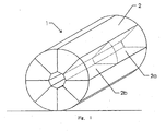
- roller is indicated in its entirety by the reference numeral 1.
- the roller 1 consists of a plurality of interconnected fluid-tight compartments 2, which through filling with fluid 3' can apply a pressure upon the subsurface. Displacing the fluid 3' between the compartment 2 can produce a force which propels the roller 1.
- the roller 1 can exert a great pressure upon one point and can propel itself, so that the sand pack according to the prior art is no longer necessary.
- a water-filled roller with a 10-metre diameter can deliver a pressure of 78 tonnes per metre of width.
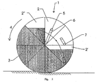
- the roller 1 can supply energy to the propulsion by in the vertical plane filling more compartments 2 with fluid in one half of the roller 1 than in the other half.
- the roller 1 will move in the direction 4 of the half with the heavier filling, as indicated in Fig. 2 .
- All compartments have at least one fluid connection 5 through which the fluid 3' can be pumped into or out of the compartment 2. If the connection 5 is situated on the side of a compartment 2, the lowest point for pumping out can be found by placing a hose 6 with a weighted suction nozzle 7 in the compartment 2.
- a selection can be made from one or more compartments 2' which are to be pumped out and a selection can be made of one or more compartments 2" which are to be pumped full.
- Connecting the selected compartments 2 to the inlet or outlet of a fluid pump by means of controllable shut-off valves means that the energy can be built to move the roller 1 in the desired direction. Aeration and deaeration are a part of this process.
- the width of the roller 1 may have to be greater than its height.
- the roller 1 will be propelled in a straight line. If the compartments 2 are divided internally into segments 2a, 2b, as can be seen in Figure 1 , the direction of propulsion can be influence to some extent by uneven filling of the divided compartments 2. The direction of propulsion can also be influenced by connecting rollers to each other, with one roller delivering more forward power than the other.
- the compartments 2 can be of different shapes, depending on the application.
- the roller 1 will propel itself gradually (in a jolting movement) if the compartments 2 are the shape of sectors of a circle which together give the roller 1 a round outside shape like that shown in Figs 1 and 2 .
- the roller will produce a shock in the subsurface if the compartments do not form a round external shape, and after overcoming the dead centre position the roller falls over onto the next compartment.
- Fig. 3 shows an embodiment in which the compartments 2 comprise flattened outer circumferential walls 10. If the roller 1 propels itself or is propelled during operation, it is advantageous for vibrations to occur in the subsurface as it turns over from the one compartment to the other. These local vibrations contribute to the compaction of the subsurface, as does the shock of the roller turning over from the one compartment to the other.
- Fig. 4 shows a variant in which the roller is made up of a plurality of cylindrical compartments 15 mounted on two intermediate frames 16.
- the compartments 15 are provided with fluid chambers here.
- pumping means or other types of drive devices can be accommodated in the central space 17 left clear between the compartments 15. This means that this variant also can be in the form of a stand-alone unit.
- each fluid chamber 3 of each compartment 2 is provided with a pumping-out connection 20, which is connected by way of a shut-off value 21 to a pumping-out line 22, and each compartment is also provided with a pumping-in connection 24, which is connected by way of a shut-off valve 25 to a pumping-in line 26.
- the lines 22, 26 here are in the form of ring lines extending along and/or through the fluid chambers 3.
- a pump 28 is provided between the pumping-out line 22 and the pumping-in line 26. Flows can be produced between certain compartments 2 by controlling the pump 28 and the shut-off valves 21, 25 in a suitable manner by way of the control unit (not shown). An example of this is given by 30 with pump 28 put into operation and with opened shut-off valves 21', 25'. The appropriate weight shift within the roller 1 will cause the roller 1 to be propelled in the direction 4.
- Fig. 5 It is also clearly visible in Fig. 5 that the sector-shaped compartments 2 are truncated, so that a clear space is produced in the centre of the roller body.
- the control unit (not shown), for example, can be accommodated in this space.
- the truncation further means that material is saved and the height of an individual compartment remains limited. This simplifies transport by, for example, road.
- the individual compartments can be mounted directly connected to each other on an intermediate frame, or can be held together in another way.
- the connection is such that the compartments are easy to assemble and disassemble, and is formed, for example, by a sliding connection or a bolted connection.
- a plate-shaped element can be fitted around the assembly of the compartments, which plate-shaped element during operation ultimately rests against the subsurface to be worked.
- the compartments can also be of a different shape, and in the assembled state may rest against each other or be separated. If there are a plurality of compartment segments lying adjacent to each other in the axial direction, said segments can be formed by internally placed partitions.
- compartment segments In a variant it is also possible to make the compartment segments completely separate from each other and connect them to each other during assembly.
- the compartments can also be obtained by partition walls which are placed in a sealing manner inside a sleeve-shaped element and separate the compartments from each other.
- the pumping means can be formed by an external pumping unit, but can also be accommodated inside the assembly of compartments.
- the compartments are preferably of the same design. This simplifies production and also the assembly.
- the fluid used is preferably water, but another fluid or filling agent such as, for example, sand is also possible.
- roller which can exert great pressure upon the subsurface is obtained, with the result that the layers of ground are tamped. If the roller consists of sector-shaped compartments with a round external shape, this will cause a reasonably uniform pressure. If the roller consists of a circle of compartments which do not form a uniform outside, this will cause a pulsating pressure.
- the roller can be sent at different pressures by detering the quantity of fluid present in the roller. By displacing the fluid between compartments, the roller can shift the centre of gravity and move itself as a result.
- the direction of movement can be adjusted by dividing the compartments up internally and filling these parts unequally.
- the direction of movement can be adjusted by connecting rollers together and filling the rollers unequally. If water is used as the fluid, this "weight" does not need to be brought in.
- the roller can be assembled and disassembled, and is movable.
Landscapes
- Engineering & Computer Science (AREA)
- Life Sciences & Earth Sciences (AREA)
- Soil Sciences (AREA)
- Structural Engineering (AREA)
- Paleontology (AREA)
- Mechanical Engineering (AREA)
- General Life Sciences & Earth Sciences (AREA)
- Mining & Mineral Resources (AREA)
- Agronomy & Crop Science (AREA)
- Civil Engineering (AREA)
- General Engineering & Computer Science (AREA)
- Environmental & Geological Engineering (AREA)
- Environmental Sciences (AREA)
- Road Paving Machines (AREA)
- Rolls And Other Rotary Bodies (AREA)
- Investigation Of Foundation Soil And Reinforcement Of Foundation Soil By Compacting Or Drainage (AREA)
- Reduction Rolling/Reduction Stand/Operation Of Reduction Machine (AREA)
- Conveying And Assembling Of Building Elements In Situ (AREA)
- Soil Working Implements (AREA)
Claims (17)
- Walze zum Verdichten eines Untergrunds, insbesondere für den Straßenbau, aufweisend einen Walzenkörper mit einer Mittelachse, wobei der Walzenkörper aus mehreren Fächern (2) gebildet ist, wobei die Fächer (2) in Umfangsrichtung um die Mittelachse verteilt vorgesehen sind, wobei jedes Fach (2) wenigstens eine Fluidkammer (3) aufweist, wobei sich die Fluidkammern (3) in den Fächern (2) miteinander in Strömungsverbindung befinden, wobei ein Pumpmittel (28) zum Pumpen eines Fluids (3') zwischen den Fluidkammern (3) in den Fächern (2) vorgesehen ist, dadurch gekennzeichnet, dass eine Steuereinheit darin vorgesehen ist, wobei die Steuereinheit zum Pumpen des Fluids (3') aus einer Fluidkammer (3) in einem Fach (2'), die zu diesem Zeitpunkt bezüglich der vorgesehenen Walzenrichtung hinten liegt, in eine Fluidkammer (3) in einem Fach (2"), die zu diesem Zeitpunkt bezüglich der vorgesehenen Walzenrichtung (4) vorne liegt, eingerichtet ist.
- Walze nach dem vorhergehenden Anspruch, wobei ein Antriebsmittel zum Antreiben der Walze in dem Walzenkörper aufgenommen ist.
- Walze nach einem der vorhergehenden Ansprüche, wobei der Walzenkörper in Axialrichtung aus mehreren Fachsegmenten (2a, 2b) gebildet ist, die benachbart zueinander liegen.
- Walze nach Anspruch 3, wobei eine Steuereinheit vorgesehen ist, wobei die Steuereinheit zum Pumpen des Fluids (3') während des Betriebs aus einer Fluidkammer (3) in dem einen Fachsegment (2a, 2b) in eine Fluidkammer (3) in einem Fachsegment (2a, 2b), das seitlich relativ dazu gelegen ist, eingerichtet ist.
- Walze nach einem der Ansprüche 2 - 4, wobei jedes Fach (2) eine externe Fluidverbindung (5) aufweist.
- Walze nach einem der vorhergehenden Ansprüche, wobei die Fächer (2) eine Gestalt in Form eines Kreissektors im Querschnitt betrachtet aufweisen.
- Walze nach Anspruch 6, wobei die sektorförmigen Fächer (2) kegelstumpfartig sind.
- Walze nach einem der vorhergehenden Ansprüche, wobei die Fächer (2) zusammen eine Außenumfangsfläche begrenzen, die im Wesentlichen zylinderförmig ist.
- Walze nach einem der vorhergehenden Ansprüche, wobei die Fächer (2) zusammen eine Außenumfangsfläche begrenzen, die nichtrunde Teile umfasst, insbesondere abgeflachte Teile (10).
- Walze nach einem der vorhergehenden Ansprüche, wobei die Fächer (2) derart verteilt angebracht sind, dass sie in der Umfangsrichtung um die Mittelachse benachbart sind.
- Walze nach einem der vorhergehenden Ansprüche, wobei die Anordnung der Fächer (2) einen Außendurchmesser von wenigstens 3 Metern aufweist.
- Walze nach einem der vorhergehenden Ansprüche, wobei die Fächer (2) dieselbe Gestalt aufweisen.
- salze nach einem der vorhergehenden Ansprüche, wobei die Anordnung der Fächer (2) einen länglichen Walzenkörper bildet.
- salze nach einem der vorhergehenden Ansprüche, wobei die Fächer (2) lösbar miteinander verbunden sind.
- Verfahren zur Verwendung einer Walze nach einem der vorhergehenden Ansprüche, aufweisend die Schritte:- Transportieren der Fächer (2) an einen gewünschten Ort;- Antreiben der Anordnung der Fächer (2) über den zu bearbeitenden Untergrund;- Befüllen eines oder mehrerer Fächer (2) mit einem Fluid (3'), wobei der Schritt des Antreibens wenigstens mittels Pumpen des Fluids (3') aus dem einen Fach (2') in das andere Fach (2'') unterstützt wird.
- Verfahren nach Anspruch 15, wobei das Fluid Wasser ist.
- Verfahren nach einem der Ansprüche 15 - 16, wobei der Schritt des Transportierens mit demontierten Fächern (2) ausgeführt wird, wobei die Fächer (2) zum Bilden des Walzenkörpers nach dem Erreichen des gewünschten Orts montiert werden.
Priority Applications (1)
| Application Number | Priority Date | Filing Date | Title |
|---|---|---|---|
| PL06824253T PL1948872T3 (pl) | 2005-11-14 | 2006-11-07 | Walec z przedziałami dla inżynierii lądowej i wodnej |
Applications Claiming Priority (2)
| Application Number | Priority Date | Filing Date | Title |
|---|---|---|---|
| NL1030416A NL1030416C2 (nl) | 2005-11-14 | 2005-11-14 | Civiele compartimenten wals. |
| PCT/NL2006/000558 WO2007055567A1 (en) | 2005-11-14 | 2006-11-07 | Civil engineering compartmented roller |
Publications (2)
| Publication Number | Publication Date |
|---|---|
| EP1948872A1 EP1948872A1 (de) | 2008-07-30 |
| EP1948872B1 true EP1948872B1 (de) | 2009-07-01 |
Family
ID=36425255
Family Applications (1)
| Application Number | Title | Priority Date | Filing Date |
|---|---|---|---|
| EP06824253A Not-in-force EP1948872B1 (de) | 2005-11-14 | 2006-11-07 | Unterteilte walze für das bauwesen |
Country Status (12)
| Country | Link |
|---|---|
| US (1) | US7775742B2 (de) |
| EP (1) | EP1948872B1 (de) |
| CN (1) | CN101305134B (de) |
| AT (1) | ATE435337T1 (de) |
| BR (1) | BRPI0618535A2 (de) |
| DE (1) | DE602006007609D1 (de) |
| ES (1) | ES2327166T3 (de) |
| NL (1) | NL1030416C2 (de) |
| PL (1) | PL1948872T3 (de) |
| PT (1) | PT1948872E (de) |
| RU (1) | RU2412306C2 (de) |
| WO (1) | WO2007055567A1 (de) |
Families Citing this family (12)
| Publication number | Priority date | Publication date | Assignee | Title |
|---|---|---|---|---|
| FR2926737A1 (fr) * | 2008-01-28 | 2009-07-31 | Jean Pierre Belin | Broyeur niveleur universel. |
| EP2558649B1 (de) * | 2010-04-16 | 2014-11-19 | Ammann Schweiz AG | Anordnung zur bereitstellung einer pulsierenden druckkraft |
| US12123152B2 (en) | 2015-10-23 | 2024-10-22 | Ligchine International Corporation | Side-step concrete screeding apparatus |
| RU2642700C1 (ru) * | 2017-01-20 | 2018-01-25 | Викторий Данилович Девяткин | Водоплавающий одноосный складной самоходный дорожный большегрузный грунтоуплотняющий каток с изменяемой площадью контакта и бесступенчатым регулированием скорости движения, частоты колебаний и их направлением, и варианты его применения |
| EP3642419A4 (de) * | 2017-06-19 | 2021-01-20 | Volvo Construction Equipment AB | Einzeltrommel-oberflächenkompaktor |
| US11560727B2 (en) | 2018-10-08 | 2023-01-24 | Ligchine International Corporation | Apparatus for screeding concrete |
| US11162232B2 (en) | 2018-10-08 | 2021-11-02 | Ligchine International Corporation | Drive system for screeding concrete |
| CN110419272B (zh) * | 2019-09-03 | 2022-03-29 | 东北农业大学 | 镇压辊可调式筑埂器 |
| US11421390B2 (en) * | 2020-10-22 | 2022-08-23 | Caterpillar Paving Products Inc. | Adjustable mass eccentric for multi-amplitude vibratory mechanism for compactor and system and method thereof |
| WO2022182755A1 (en) | 2021-02-23 | 2022-09-01 | Ligchine International Corporation | Swing boom concrete screeding apparatus |
| WO2022232915A1 (en) * | 2021-05-03 | 2022-11-10 | S6 Innovations Inc. | Line restoration tools, drums for use therewith, and methods of using the same |
| US12378082B2 (en) | 2021-10-25 | 2025-08-05 | Ligchine International Corporation | Portable telescopic conveyor belt |
Family Cites Families (10)
| Publication number | Priority date | Publication date | Assignee | Title |
|---|---|---|---|---|
| US3662657A (en) * | 1970-07-09 | 1972-05-16 | Francesco Aiuppa | Turf roller for tractor |
| US4861187A (en) * | 1987-04-14 | 1989-08-29 | Tana Jyra Ky | Method for arranging the cooling in a compactor and a cooling system for the realization of the method |
| CN2122170U (zh) * | 1990-11-07 | 1992-11-18 | 徐州工程机械制造厂 | 振动振荡压路机 |
| US5511901A (en) | 1994-10-25 | 1996-04-30 | Ingersoll-Rand Company | Removable padfoot shell conversion device |
| DE19648593C2 (de) * | 1996-11-23 | 2000-10-12 | Wacker Werke Kg | Vibrationswalze |
| RU2151837C1 (ru) * | 1998-10-19 | 2000-06-27 | Хабаровский государственный технический университет | Вибрационный валец катка |
| DE29914838U1 (de) * | 1999-08-25 | 2001-01-04 | BOMAG GmbH & Co. oHG, 56154 Boppard | Vorrichtung für die Bodenverdichtung |
| RU21401U1 (ru) * | 2000-01-26 | 2002-01-20 | Сибирская государственная автомобильно-дорожная академия | Валец дорожного катка |
| CN2469039Y (zh) * | 2001-03-15 | 2002-01-02 | 三一重工股份有限公司 | 压路机调重装置 |
| US6764275B1 (en) * | 2002-06-28 | 2004-07-20 | Dennis L. Carr | Fluid displacement rotational assembly |
-
2005
- 2005-11-14 NL NL1030416A patent/NL1030416C2/nl not_active IP Right Cessation
-
2006
- 2006-11-07 PL PL06824253T patent/PL1948872T3/pl unknown
- 2006-11-07 CN CN2006800421682A patent/CN101305134B/zh not_active Expired - Fee Related
- 2006-11-07 BR BRPI0618535-5A patent/BRPI0618535A2/pt not_active IP Right Cessation
- 2006-11-07 PT PT06824253T patent/PT1948872E/pt unknown
- 2006-11-07 DE DE602006007609T patent/DE602006007609D1/de active Active
- 2006-11-07 AT AT06824253T patent/ATE435337T1/de not_active IP Right Cessation
- 2006-11-07 RU RU2008123833/03A patent/RU2412306C2/ru active
- 2006-11-07 ES ES06824253T patent/ES2327166T3/es active Active
- 2006-11-07 EP EP06824253A patent/EP1948872B1/de not_active Not-in-force
- 2006-11-07 WO PCT/NL2006/000558 patent/WO2007055567A1/en not_active Ceased
- 2006-11-07 US US12/093,051 patent/US7775742B2/en not_active Expired - Fee Related
Also Published As
| Publication number | Publication date |
|---|---|
| DE602006007609D1 (de) | 2009-08-13 |
| BRPI0618535A2 (pt) | 2011-09-06 |
| US20080267705A1 (en) | 2008-10-30 |
| RU2008123833A (ru) | 2009-12-27 |
| PL1948872T3 (pl) | 2009-10-30 |
| CN101305134B (zh) | 2012-11-07 |
| ATE435337T1 (de) | 2009-07-15 |
| PT1948872E (pt) | 2009-07-29 |
| ES2327166T3 (es) | 2009-10-26 |
| EP1948872A1 (de) | 2008-07-30 |
| CN101305134A (zh) | 2008-11-12 |
| RU2412306C2 (ru) | 2011-02-20 |
| NL1030416C2 (nl) | 2007-05-15 |
| US7775742B2 (en) | 2010-08-17 |
| WO2007055567A1 (en) | 2007-05-18 |
Similar Documents
| Publication | Publication Date | Title |
|---|---|---|
| EP1948872B1 (de) | Unterteilte walze für das bauwesen | |
| US5018955A (en) | Decorative curbing machine | |
| CA2952884C (en) | Hand-portable directional drill | |
| US4964753A (en) | Three roll compactor | |
| CN113455130A (zh) | 一种高龄植被土层的松土、施肥一体化装置 | |
| FI75015C (fi) | Foerfarande foer framstaellning av vaeltar av olika storlekar och genom foerfarandet framstaelld vaelt samt vaeltserie. | |
| US6749783B2 (en) | Tango II soil block press | |
| CN105442602B (zh) | 一种堤坝溃口机械化植桩筑坝机及其方法 | |
| GB1590346A (en) | Process for excavating and constructing tunnel | |
| CN112176806B (zh) | 稳定型道路软基处理方法以及配套的软基处理施工系统 | |
| CA2047446A1 (en) | System for making concrete floors | |
| DE102013109601A1 (de) | Speicherkraftwerk | |
| US20160102437A1 (en) | Modular Compactor Frame Construction | |
| JP2740842B2 (ja) | 高圧気体の岩盤内貯蔵方法および高圧気体貯蔵用岩盤タンク | |
| KR100476907B1 (ko) | 가변식 보링 머신 추진공법 및 그 장치 | |
| KR101507462B1 (ko) | 관부재 추진장치 | |
| KR101075445B1 (ko) | 지중 추진관용 분쇄식 굴착장치 | |
| KR102721639B1 (ko) | 준설토 진입용 연약지반 개량 장치를 이용한 시공 방법 | |
| EP3448142B1 (de) | System und verfahren zum aufrollen einer flexiblen folie | |
| DE924198C (de) | Verfahren und Geraet zur Herstellung unterirdischer Kanaele | |
| KR102230972B1 (ko) | 친환경 세미실드 굴착장치 | |
| CN220035499U (zh) | 一种装配式生态挡墙 | |
| JPH06129184A (ja) | 配管を地下埋設するための掘進装置 | |
| JPH0237918Y2 (de) | ||
| JP5994065B2 (ja) | 建物の沈下修正基礎構造 |
Legal Events
| Date | Code | Title | Description |
|---|---|---|---|
| PUAI | Public reference made under article 153(3) epc to a published international application that has entered the european phase |
Free format text: ORIGINAL CODE: 0009012 |
|
| 17P | Request for examination filed |
Effective date: 20080526 |
|
| AK | Designated contracting states |
Kind code of ref document: A1 Designated state(s): AT BE BG CH CY CZ DE DK EE ES FI FR GB GR HU IE IS IT LI LT LU LV MC NL PL PT RO SE SI SK TR |
|
| GRAP | Despatch of communication of intention to grant a patent |
Free format text: ORIGINAL CODE: EPIDOSNIGR1 |
|
| GRAS | Grant fee paid |
Free format text: ORIGINAL CODE: EPIDOSNIGR3 |
|
| GRAA | (expected) grant |
Free format text: ORIGINAL CODE: 0009210 |
|
| AK | Designated contracting states |
Kind code of ref document: B1 Designated state(s): AT BE BG CH CY CZ DE DK EE ES FI FR GB GR HU IE IS IT LI LT LU LV MC NL PL PT RO SE SI SK TR |
|
| REG | Reference to a national code |
Ref country code: GB Ref legal event code: FG4D |
|
| REG | Reference to a national code |
Ref country code: CH Ref legal event code: EP |
|
| REG | Reference to a national code |
Ref country code: PT Ref legal event code: SC4A Free format text: AVAILABILITY OF NATIONAL TRANSLATION Effective date: 20090722 |
|
| REG | Reference to a national code |
Ref country code: RO Ref legal event code: EPE Ref country code: IE Ref legal event code: FG4D |
|
| REF | Corresponds to: |
Ref document number: 602006007609 Country of ref document: DE Date of ref document: 20090813 Kind code of ref document: P |
|
| REG | Reference to a national code |
Ref country code: GR Ref legal event code: EP Ref document number: 20090402040 Country of ref document: GR |
|
| REG | Reference to a national code |
Ref country code: ES Ref legal event code: FG2A Ref document number: 2327166 Country of ref document: ES Kind code of ref document: T3 |
|
| REG | Reference to a national code |
Ref country code: PL Ref legal event code: T3 |
|
| PG25 | Lapsed in a contracting state [announced via postgrant information from national office to epo] |
Ref country code: SI Free format text: LAPSE BECAUSE OF FAILURE TO SUBMIT A TRANSLATION OF THE DESCRIPTION OR TO PAY THE FEE WITHIN THE PRESCRIBED TIME-LIMIT Effective date: 20090701 |
|
| PG25 | Lapsed in a contracting state [announced via postgrant information from national office to epo] |
Ref country code: AT Free format text: LAPSE BECAUSE OF FAILURE TO SUBMIT A TRANSLATION OF THE DESCRIPTION OR TO PAY THE FEE WITHIN THE PRESCRIBED TIME-LIMIT Effective date: 20090701 Ref country code: EE Free format text: LAPSE BECAUSE OF FAILURE TO SUBMIT A TRANSLATION OF THE DESCRIPTION OR TO PAY THE FEE WITHIN THE PRESCRIBED TIME-LIMIT Effective date: 20090701 Ref country code: SE Free format text: LAPSE BECAUSE OF FAILURE TO SUBMIT A TRANSLATION OF THE DESCRIPTION OR TO PAY THE FEE WITHIN THE PRESCRIBED TIME-LIMIT Effective date: 20090701 Ref country code: FI Free format text: LAPSE BECAUSE OF FAILURE TO SUBMIT A TRANSLATION OF THE DESCRIPTION OR TO PAY THE FEE WITHIN THE PRESCRIBED TIME-LIMIT Effective date: 20090701 Ref country code: IS Free format text: LAPSE BECAUSE OF FAILURE TO SUBMIT A TRANSLATION OF THE DESCRIPTION OR TO PAY THE FEE WITHIN THE PRESCRIBED TIME-LIMIT Effective date: 20091101 |
|
| PG25 | Lapsed in a contracting state [announced via postgrant information from national office to epo] |
Ref country code: BG Free format text: LAPSE BECAUSE OF FAILURE TO SUBMIT A TRANSLATION OF THE DESCRIPTION OR TO PAY THE FEE WITHIN THE PRESCRIBED TIME-LIMIT Effective date: 20091001 |
|
| PG25 | Lapsed in a contracting state [announced via postgrant information from national office to epo] |
Ref country code: DK Free format text: LAPSE BECAUSE OF FAILURE TO SUBMIT A TRANSLATION OF THE DESCRIPTION OR TO PAY THE FEE WITHIN THE PRESCRIBED TIME-LIMIT Effective date: 20090701 |
|
| PLBE | No opposition filed within time limit |
Free format text: ORIGINAL CODE: 0009261 |
|
| STAA | Information on the status of an ep patent application or granted ep patent |
Free format text: STATUS: NO OPPOSITION FILED WITHIN TIME LIMIT |
|
| PG25 | Lapsed in a contracting state [announced via postgrant information from national office to epo] |
Ref country code: SK Free format text: LAPSE BECAUSE OF FAILURE TO SUBMIT A TRANSLATION OF THE DESCRIPTION OR TO PAY THE FEE WITHIN THE PRESCRIBED TIME-LIMIT Effective date: 20090701 |
|
| 26N | No opposition filed |
Effective date: 20100406 |
|
| PG25 | Lapsed in a contracting state [announced via postgrant information from national office to epo] |
Ref country code: MC Free format text: LAPSE BECAUSE OF NON-PAYMENT OF DUE FEES Effective date: 20091130 |
|
| PG25 | Lapsed in a contracting state [announced via postgrant information from national office to epo] |
Ref country code: IE Free format text: LAPSE BECAUSE OF NON-PAYMENT OF DUE FEES Effective date: 20091107 |
|
| PG25 | Lapsed in a contracting state [announced via postgrant information from national office to epo] |
Ref country code: LU Free format text: LAPSE BECAUSE OF NON-PAYMENT OF DUE FEES Effective date: 20091107 |
|
| PG25 | Lapsed in a contracting state [announced via postgrant information from national office to epo] |
Ref country code: HU Free format text: LAPSE BECAUSE OF FAILURE TO SUBMIT A TRANSLATION OF THE DESCRIPTION OR TO PAY THE FEE WITHIN THE PRESCRIBED TIME-LIMIT Effective date: 20100102 |
|
| REG | Reference to a national code |
Ref country code: CH Ref legal event code: PL |
|
| PG25 | Lapsed in a contracting state [announced via postgrant information from national office to epo] |
Ref country code: CH Free format text: LAPSE BECAUSE OF NON-PAYMENT OF DUE FEES Effective date: 20101130 Ref country code: LI Free format text: LAPSE BECAUSE OF NON-PAYMENT OF DUE FEES Effective date: 20101130 |
|
| PG25 | Lapsed in a contracting state [announced via postgrant information from national office to epo] |
Ref country code: CY Free format text: LAPSE BECAUSE OF FAILURE TO SUBMIT A TRANSLATION OF THE DESCRIPTION OR TO PAY THE FEE WITHIN THE PRESCRIBED TIME-LIMIT Effective date: 20090701 |
|
| PGFP | Annual fee paid to national office [announced via postgrant information from national office to epo] |
Ref country code: LT Payment date: 20140909 Year of fee payment: 9 |
|
| PGFP | Annual fee paid to national office [announced via postgrant information from national office to epo] |
Ref country code: LV Payment date: 20140909 Year of fee payment: 9 |
|
| REG | Reference to a national code |
Ref country code: FR Ref legal event code: PLFP Year of fee payment: 10 |
|
| REG | Reference to a national code |
Ref country code: LT Ref legal event code: MM4D Effective date: 20151107 |
|
| PG25 | Lapsed in a contracting state [announced via postgrant information from national office to epo] |
Ref country code: LV Free format text: LAPSE BECAUSE OF NON-PAYMENT OF DUE FEES Effective date: 20151107 Ref country code: LT Free format text: LAPSE BECAUSE OF NON-PAYMENT OF DUE FEES Effective date: 20151107 |
|
| REG | Reference to a national code |
Ref country code: FR Ref legal event code: PLFP Year of fee payment: 11 |
|
| REG | Reference to a national code |
Ref country code: FR Ref legal event code: PLFP Year of fee payment: 12 |
|
| REG | Reference to a national code |
Ref country code: NL Ref legal event code: PD Owner name: GIANT ROLLER B.V.; NL Free format text: DETAILS ASSIGNMENT: CHANGE OF OWNER(S), ASSIGNMENT; FORMER OWNER NAME: BUYSMAN HOLDING B.V. Effective date: 20171221 |
|
| PGFP | Annual fee paid to national office [announced via postgrant information from national office to epo] |
Ref country code: RO Payment date: 20191024 Year of fee payment: 14 |
|
| PGFP | Annual fee paid to national office [announced via postgrant information from national office to epo] |
Ref country code: BE Payment date: 20191126 Year of fee payment: 14 Ref country code: GR Payment date: 20191024 Year of fee payment: 14 Ref country code: IT Payment date: 20191129 Year of fee payment: 14 |
|
| PGFP | Annual fee paid to national office [announced via postgrant information from national office to epo] |
Ref country code: ES Payment date: 20200224 Year of fee payment: 14 |
|
| PGFP | Annual fee paid to national office [announced via postgrant information from national office to epo] |
Ref country code: NL Payment date: 20201119 Year of fee payment: 15 Ref country code: TR Payment date: 20201013 Year of fee payment: 15 |
|
| PGFP | Annual fee paid to national office [announced via postgrant information from national office to epo] |
Ref country code: PT Payment date: 20201007 Year of fee payment: 15 Ref country code: CZ Payment date: 20201008 Year of fee payment: 15 Ref country code: DE Payment date: 20201123 Year of fee payment: 15 Ref country code: FR Payment date: 20201126 Year of fee payment: 15 Ref country code: GB Payment date: 20201124 Year of fee payment: 15 |
|
| PGFP | Annual fee paid to national office [announced via postgrant information from national office to epo] |
Ref country code: PL Payment date: 20201006 Year of fee payment: 15 |
|
| PG25 | Lapsed in a contracting state [announced via postgrant information from national office to epo] |
Ref country code: RO Free format text: LAPSE BECAUSE OF NON-PAYMENT OF DUE FEES Effective date: 20201107 Ref country code: GR Free format text: LAPSE BECAUSE OF NON-PAYMENT OF DUE FEES Effective date: 20210608 |
|
| REG | Reference to a national code |
Ref country code: BE Ref legal event code: MM Effective date: 20201130 |
|
| PG25 | Lapsed in a contracting state [announced via postgrant information from national office to epo] |
Ref country code: IT Free format text: LAPSE BECAUSE OF NON-PAYMENT OF DUE FEES Effective date: 20201107 |
|
| REG | Reference to a national code |
Ref country code: ES Ref legal event code: FD2A Effective date: 20220202 |
|
| PG25 | Lapsed in a contracting state [announced via postgrant information from national office to epo] |
Ref country code: ES Free format text: LAPSE BECAUSE OF NON-PAYMENT OF DUE FEES Effective date: 20201108 |
|
| REG | Reference to a national code |
Ref country code: DE Ref legal event code: R119 Ref document number: 602006007609 Country of ref document: DE |
|
| REG | Reference to a national code |
Ref country code: NL Ref legal event code: MM Effective date: 20211201 |
|
| GBPC | Gb: european patent ceased through non-payment of renewal fee |
Effective date: 20211107 |
|
| PG25 | Lapsed in a contracting state [announced via postgrant information from national office to epo] |
Ref country code: PT Free format text: LAPSE BECAUSE OF NON-PAYMENT OF DUE FEES Effective date: 20220509 Ref country code: CZ Free format text: LAPSE BECAUSE OF NON-PAYMENT OF DUE FEES Effective date: 20211107 Ref country code: BE Free format text: LAPSE BECAUSE OF NON-PAYMENT OF DUE FEES Effective date: 20201130 |
|
| PG25 | Lapsed in a contracting state [announced via postgrant information from national office to epo] |
Ref country code: NL Free format text: LAPSE BECAUSE OF NON-PAYMENT OF DUE FEES Effective date: 20211201 |
|
| PG25 | Lapsed in a contracting state [announced via postgrant information from national office to epo] |
Ref country code: GB Free format text: LAPSE BECAUSE OF NON-PAYMENT OF DUE FEES Effective date: 20211107 Ref country code: DE Free format text: LAPSE BECAUSE OF NON-PAYMENT OF DUE FEES Effective date: 20220601 |
|
| PG25 | Lapsed in a contracting state [announced via postgrant information from national office to epo] |
Ref country code: FR Free format text: LAPSE BECAUSE OF NON-PAYMENT OF DUE FEES Effective date: 20211130 |
|
| PG25 | Lapsed in a contracting state [announced via postgrant information from national office to epo] |
Ref country code: PL Free format text: LAPSE BECAUSE OF NON-PAYMENT OF DUE FEES Effective date: 20211107 |
|
| PG25 | Lapsed in a contracting state [announced via postgrant information from national office to epo] |
Ref country code: PL Free format text: LAPSE BECAUSE OF NON-PAYMENT OF DUE FEES Effective date: 20201107 |
|
| PG25 | Lapsed in a contracting state [announced via postgrant information from national office to epo] |
Ref country code: TR Free format text: LAPSE BECAUSE OF NON-PAYMENT OF DUE FEES Effective date: 20211107 |