EP1948507B1 - Porte de coffre a bagages et coffre a bagages - Google Patents
Porte de coffre a bagages et coffre a bagages Download PDFInfo
- Publication number
- EP1948507B1 EP1948507B1 EP06830994A EP06830994A EP1948507B1 EP 1948507 B1 EP1948507 B1 EP 1948507B1 EP 06830994 A EP06830994 A EP 06830994A EP 06830994 A EP06830994 A EP 06830994A EP 1948507 B1 EP1948507 B1 EP 1948507B1
- Authority
- EP
- European Patent Office
- Prior art keywords
- flap
- luggage compartment
- luggage
- door
- luggage bin
- Prior art date
- Legal status (The legal status is an assumption and is not a legal conclusion. Google has not performed a legal analysis and makes no representation as to the accuracy of the status listed.)
- Ceased
Links
Images


Classifications
-
- B—PERFORMING OPERATIONS; TRANSPORTING
- B64—AIRCRAFT; AVIATION; COSMONAUTICS
- B64D—EQUIPMENT FOR FITTING IN OR TO AIRCRAFT; FLIGHT SUITS; PARACHUTES; ARRANGEMENT OR MOUNTING OF POWER PLANTS OR PROPULSION TRANSMISSIONS IN AIRCRAFT
- B64D11/00—Passenger or crew accommodation; Flight-deck installations not otherwise provided for
- B64D11/003—Stowage devices for passengers' personal luggage
Definitions
- the present invention relates to a luggage compartment door, including luggage compartment in an aircraft, and a corresponding luggage compartment.
- the cross section of a boot in an aircraft has a substantially trapezoidal shape, the large base of the trapezoid forming the underside of the boot.
- the bottom of the luggage compartment is longer to accommodate large luggage while the upper part is narrower to retain any luggage placed on other luggage in the trunk and prevent it from falling, especially when opening the luggage compartment. the luggage compartment door.
- the present invention therefore aims to provide a luggage compartment door that allows to give free rein to define the shape that designers want to give to the interior space of the aircraft.
- a boot with a door allowing access to a compartment with a lower face having a substantially flat area near the door, the door having, in the closed position, a first flap inclined towards the door. interior of the luggage compartment relative to a plane perpendicular to the substantially flat area of the underside of the luggage compartment, said first flap being pivotally mounted about a first axis.
- the access door of the luggage compartment further comprises a second flap disposed outside the first flap relative to the luggage compartment and articulated on the first flap, and the second flap extends, in closing position of the luggage compartment, from a lower edge of the luggage compartment to a ceiling edge.
- a luggage compartment door of the prior art has only one flap which is usually also called door or access door.
- the two doors of the luggage compartment door cooperate to close the luggage compartment.
- One flap serves in particular to maintain the luggage (s) in the luggage compartment while the other flap takes the desired shape to achieve the desired aesthetic effect. With such a door having two flaps, it can achieve any external appearance while ensuring a good hold of luggage inside the luggage compartment.
- the second flap is, in a preferred embodiment, articulated on the first flap so as to be pivotable with respect to this first flap about a second pivot axis substantially parallel to the first flap.
- the two flaps can be folded over one another in the open position of the luggage compartment is thus fully clear the opening of the luggage compartment, facilitating access to the interior of this one.
- the first flap only partially closes the luggage compartment. This allows in particular to incline more strongly the first component relative to the underside of the luggage compartment and thus be more effective for holding luggage in the trunk.
- the latter advantageously also comprises means allowing, when it opens, to maintain the second flap in contact with said ceiling edge.
- the second component is then articulated on the first part and guided on the edge of the ceiling.
- the means for maintaining the second flap in contact with the edge of the ceiling comprise for example a spring acting to separate the second flap of the first flap. This spring is advantageously integrated with the articulation between the two flaps so as to limit its bulk and better integrate into the door.
- locking means are for example arranged on the second flap.
- the present invention also relates to an aircraft cabin, characterized in that it comprises at least one luggage compartment as described above and an aircraft comprises at least one such luggage compartment.
- a luggage compartment according to the invention conventionally comprises a lower face 2, an upper face 4 and, between the lower face 2 and the upper face 4, two side walls 6 and a bottom wall 8. Access to the trunk luggage is by the opposite side to the bottom wall which is provided with a door.
- the trunk shown in the drawings is in an aircraft cabin, above seats (not shown) located in this cabin, under the ceiling thereof.
- a ceiling wall 10 is shown in the figures.
- the lower surface 2 of the luggage compartment is intended to receive one (or more) luggage (s) 12.
- the lower face 2 is a flat face. It is slightly inclined relative to the horizontal so as to facilitate the extraction of the luggage 12 out of the luggage compartment.
- the side walls 6, the bottom wall 8 and the upper face 4 define the volume of the luggage compartment. These walls may be clean walls to the luggage compartment, as shown here. It can also be common walls with other elements such as another trunk.
- the bottom 8 may be for example also the side wall of the aircraft cabin, in particular for luggage boxes located above seats arranged near such a side wall.
- the upper face 4 can be a part of the ceiling of the aircraft cabin.
- the trunk shown in the drawings is closed by a door having two components: a first flap 14 and a second flap 16.
- the second flap 16 is the visible part of the luggage compartment door for the user who has a luggage 12 in the luggage compartment or removes it.
- This second flap 16 connects the lower face 2 of the luggage compartment to the ceiling wall 10 of the aircraft cabin.
- the shape of this second flap 16 can be adapted to the aesthetics that it is desired to give inside the aircraft cabin.
- This component thus preferably provides an aesthetically harmonious connection between a fairing 18 generally located under a luggage compartment - and usually incorporating comfort elements, such as lighting, air vents, etc. - and the ceiling wall 10. .
- the first flap 14 is disposed between the second flap 16 and the storage space of the luggage compartment. This first flap 14 is visible only when the boot is open. It is especially intended to keep the luggage 12 in its place to prevent the luggage from falling out of the luggage compartment, especially when the door is opened, by keeping the luggage 12 inside the trunk.
- This first component 14 is also useful in the case where, as represented on the Figures 1 to 4 a small piece of luggage 12 is on another piece of luggage 12. It is clear ( figure 1 ) that in the absence of the first flap 14, the small luggage 12 higher could slide to the second flap 16 and tumble. At the opening of the door, the passenger would then receive this small luggage 12. The first flap 14 can effectively prevent such a fall.
- the first flap 14 is substantially flat overall shape. It is inclined relative to the underside 2 of the luggage compartment towards the inside of the trunk, when the boot is in the closed position. Thus, the angle formed by the plane containing the lower face 2 and the plane containing the first flap 14 is less than 90 °. In the case for example where the first flap 14 is not plane, it can be expected that the first flap 14 is placed in the closed position of the luggage compartment door, inside a dihedron formed of on the one hand by the lower face 2 and on the other by a plane perpendicular to the lower face 2 and passing through the lower edge 22 of the first flap 14 (cf. figure 1 ).
- the first and second flaps 14 and 16 are articulated with respect to each other at the lower edge 22 of the first flap 14. This articulation can be achieved for example by a hinge connecting the two flaps. She allows the pivoting of one flap relative to the other around a first substantially horizontal axis 24.
- the first flap 14 is also articulated about a second axis 26, parallel to the first axis 24.
- the articulation can be done at the upper face 4 of the luggage compartment. In the example shown, this articulation is more precisely at the free end of the upper face 4 of the luggage compartment. This articulation could, in another embodiment, be performed at the ceiling of the aircraft cabin.
- the two flaps 14 and 16 In the position shown on the figure 1 , corresponding to the closed position of the luggage compartment door, the two flaps 14 and 16 substantially form a dihedral relative to the first axis 24.
- One of the flaps is essentially disposed on one side of the plane perpendicular to the face 20 bottom 2 of the luggage compartment while the other flap is essentially disposed on the other side of this perpendicular plane 20.
- the first flap 14 does not necessarily extend, as is the case for the preferred embodiment shown in the drawings, over the entire height of the luggage compartment in the closed position thereof.
- a space may remain between the lower edge 22 of the first flap 14 and the lower face 2 of the luggage compartment. This space is then closed by the lower part of the second flap 16.
- This embodiment makes it possible to incline the first flap towards the inside of the luggage compartment without too much encroaching on the interior volume of this trunk.
- a locking mechanism (not shown), making it possible to keep the door in its closed position, is provided on the lower part of the second flap 16.
- Such a locking mechanism is known to those skilled in the art and is not described here.
- the upper edge of the second flap 16 comprises a rebate 28, visible in particular on the Figures 2 to 4 receiving, in the closed position of the luggage compartment door, the edge of the ceiling wall 10 facing the luggage compartment.
- the Figures 1 to 4 respectively 4 to 1, illustrate the opening and closing respectively of the door described above.
- the figure 1 represents the door in its closed position.
- the luggage 12 rests on the lower face 2.
- the second flap 16 comes to rest on the one hand at its upper edge and its rabbet 28 on the corresponding edge of the ceiling wall 10 and on the other hand its lower edge is maintained by the locking mechanism in the immediate vicinity of the free edge of the bottom face 2 of the luggage compartment.
- the first flap 14 is maintained between its two joints, one connecting the second flap 16 and the other at the free edge of the upper face of the luggage compartment.
- the locking mechanism is actuated to unlock the second flap 16. A double movement is then caused.
- the first flap 14 and the second flap 16 pivot relative to each other about the first axis 24 by reducing (during the opening of the door) the angle ⁇ formed between the two flaps .
- the first flap 14 pivots around the free edge of the upper face 4, that is to say around the second axis 26.
- elastic means are provided between the two flaps to keep them apart from each other.
- Such means are not shown in the drawings. They may for example be integrated at the first axis of articulation 24. Separate means may also be provided. Other means may also be envisaged to maintain contact between the second flap 16 and the ceiling wall. It is thus possible for example to provide on the edge of the ceiling wall 10 guiding means, the second flap 16 being equipped with complementary means.
- the second flap 16 folds over the first flap 14.
- the opening movement of the door is stopped when the two flaps are against each other and come to butter against the edge of the ceiling wall 10.
- the opening is then maximum.
- the two flaps being against each other, the opening is as large as if there were only one shutter (and therefore a conventional door of the prior art).
- Closing the luggage compartment door is done in the opposite way to the opening described above and is easily deduced.
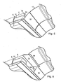
- the Figures 5 to 8 show the luggage compartment of the Figures 1 to 4 in perspective. It should be noted in these figures that on the one hand the second flap 16, the only visible part of the luggage compartment door in the closed position thereof, makes it possible to conceal the baggage compartment aesthetically and on the other hand the door according to the invention does not interfere with the removal (or setting up) of luggage in the luggage compartment.
- the first flap 14 In the closed position of the door, the first flap 14, not visible from the outside, holds the luggage 12 in the luggage compartment.
- the first component 14 is also effective when two bags, smaller than the one shown, are placed one on the other. The first flap 14 then limits the sliding of the baggage lying on the top towards the door of the boot.
Landscapes
- Engineering & Computer Science (AREA)
- Aviation & Aerospace Engineering (AREA)
- Superstructure Of Vehicle (AREA)
- Inorganic Compounds Of Heavy Metals (AREA)
- Vehicle Step Arrangements And Article Storage (AREA)
Abstract
Description
- La présente invention concerne une porte de coffre à bagages, notamment de coffre à bagages dans un aéronef, ainsi qu'un coffre à bagages correspondant.
- Généralement, la section transversale d'un coffre à bagages dans un aéronef présente une forme sensiblement trapézoïdal, la grande base du trapèze formant la face inférieure du coffre à bagages. La partie inférieure du coffre à bagages est plus longue pour recevoir de gros bagages tandis que la partie supérieure est plus étroite pour permettre de retenir un éventuel bagage posé sur un autre bagage dans le coffre et éviter sa chute, notamment lors de l'ouverture de la porte du coffre à bagages.
- Cette forme trapézoïdale imposée par des contraintes techniques est très contraignante pour définir l'esthétique du volume intérieur d'une cabine d'aéronef. Les coffres à bagages se trouvant juste en dessous du plafond, la jonction entre le coffre à bagages et le plafond forme un recoin peu esthétique.
- La présente invention a alors pour but de fournir une porte de coffre à bagages qui permette de laisser libre cours pour définir la forme que les designers souhaitent donner à l'espace intérieur de l'aéronef.
- A cet effet, elle propose un coffre à bagages comportant une porte permettant l'accès à un compartiment avec une face inférieure présentant une zone sensiblement plane à proximité de la porte, la porte présentant, en position de fermeture, un premier volet incliné vers l'intérieur du coffre à bagages par rapport à un plan perpendiculaire à la zone sensiblement plane de la face inférieure du coffre à bagages, ledit premier volet étant monté pivotant autour d'un premier axe.
- Selon la présente invention, la porte d'accès du coffre à bagages comporte en outre un second volet disposé à l'extérieur du premier volet par rapport au coffre à bagages et articulé sur le premier volet, et le second volet s'étend, en position de fermeture du coffre à bagages, depuis un bord inférieur du coffre à bagages jusqu'à un bord de plafond.
- Les premier et second volets de la définition ci-dessus constituent, avec d'autres éléments éventuels, une porte de coffre à bagages selon l'invention. Une porte de coffre à bagages de l'art antérieur ne comporte qu'un seul volet qui est généralement appelé aussi porte ou porte d'accès. Les deux volets de la porte du coffre à bagages coopèrent pour fermer le coffre à bagages. Un volet sert notamment à maintenir le(s) bagage(s) dans le coffre à bagages tandis que l'autre volet prend la forme souhaitée pour obtenir l'effet esthétique souhaité. Avec une telle porte présentant deux volets, on peut réaliser un aspect extérieur quelconque tout en garantissant un bon maintien des bagages à l'intérieur du coffre à bagages.
- Dans un coffre à bagages selon l'invention, le second volet est, dans une forme de réalisation préférée, articulé sur le premier volet de manière à pouvoir pivoter par rapport à ce premier volet autour d'un second axe de pivotement sensiblement parallèle au premier. Dans cette forme de réalisation, les deux volets peuvent se rabattre l'une sur l'autre dans la position d'ouverture du coffre à bagages est ainsi dégager entièrement l'ouverture du coffre à bagages, facilitant l'accès à l'intérieur de celui-ci.
- Dans une variante de réalisation, le premier volet ne ferme que partiellement le coffre à bagages. Ceci permet notamment d'incliner plus fortement le premier volet par rapport à la face inférieure du coffre à bagages et d'être ainsi plus efficace pour le maintien des bagages dans le coffre.
- Pour faciliter la manoeuvre de la porte du coffre à bagages, ce dernier comporte avantageusement également des moyens permettant, lors de son ouverture, de maintenir le second volet en contact avec ledit bord de plafond. Le second volet est alors d'une part articulé sur le premier volet et d'autre part guidé sur le bord du plafond. Dans cette forme de réalisation, les moyens permettant de maintenir le second volet en contact avec le bord du plafond comportent par exemple un ressort agissant de manière à écarter le second volet du premier volet. Ce ressort est avantageusement intégré à l'articulation entre les deux volets de manière à limiter son encombrement et à mieux l'intégrer dans la porte.
- Pour maintenir fermés les volets du coffre à bagages selon l'invention, des moyens de verrouillage sont par exemple disposés sur le second volet.
- La présente invention concerne également une cabine d'aéronef, caractérisée en ce qu'elle comporte au moins un coffre à bagages tel que décrit ci-dessus ainsi qu'un aéronef comporte au moins un tel coffre à bagages.
- Des détails et avantages de la présente invention ressortiront mieux de la description qui suit, faite en référence au dessin schématique annexé, sur
lequel : - La
figure 1 est une vue en coupe transversale d'un coffre à bagages selon l'invention en position fermée, - Les
figures 2 et 3 sont des vues correspondant à lafigure 1 , le coffre à bagages étant dans une position d'ouverture intermédiaire, - La
figure 4 est une vue en coupe transversale d'un coffre à bagages selon l'invention en position entièrement ouverte, - La
figure 5 est une vue en perspective d'un coffre à bagages selon l'invention en position fermée, - La
figure 6 est une vue en perspective d'un coffre à bagages selon l'invention en position ouverte, et - Les
figures 7 et 8 illustrent, en perspective, la mise en place de bagages dans le coffre à bagages desfigures 5 et 6 . - Un coffre à bagages selon l'invention comporte de manière classique une face inférieure 2, une face supérieure 4 et, entre la face inférieure 2 et la face supérieure 4, deux parois latérales 6 et une paroi de fond 8. L'accès au coffre à bagages se fait par la face opposée à la paroi de fond qui est munie d'une porte.
- Le coffre à bagages représenté aux dessins se trouve dans une cabine d'aéronef, au-dessus de sièges (non représentés) se trouvant dans cette cabine, sous le plafond de celle-ci. Une paroi de plafond 10 est représentée sur les figures.
- La face inférieure 2 du coffre à bagages est destinée à recevoir un (ou plusieurs) bagage(s) 12. Dans la forme de réalisation représentée, la face inférieure 2 est une face plane. Elle est légèrement inclinée par rapport à l'horizontale de manière à faciliter l'extraction du bagage 12 hors du coffre à bagages.
- Les parois latérales 6, la paroi de fond 8 et la face supérieure 4 délimitent le volume du coffre à bagages. Ces parois peuvent être des parois propres au coffre à bagages, comme représenté ici. Il peut également s'agir de parois communes avec d'autres éléments comme par exemple un autre coffre à bagages. Le fond 8 peut être par exemple aussi la paroi latérale de la cabine d'aéronef, notamment pour des coffres à bagages se trouvant au-dessus de sièges disposés à proximité d'une telle paroi latérale. La face supérieure 4 quant à elle peut être une partie du plafond de la cabine d'aéronef.
- Le coffre à bagages représenté aux dessins est fermé par une porte présentant deux volets : un premier volet 14 et un second volet 16.
- Le second volet 16 constitue la partie visible de la porte du coffre à bagages pour l'utilisateur qui dispose un bagage 12 dans le coffre à bagages ou l'en retire. Ce second volet 16 relie la face inférieure 2 du coffre à bagages à la paroi de plafond 10 de la cabine d'aéronef. La forme de ce second volet 16 peut être adaptée à l'esthétique que l'on souhaite donner à l'intérieur de la cabine d'aéronef. Ce volet réalise ainsi de préférence une liaison esthétiquement harmonieuse entre un carénage 18 se trouvant généralement sous un coffre à bagages -et intégrant habituellement des éléments de confort, tels des éclairages, des bouches d'aération, etc.- et la paroi de plafond 10.
- Le premier volet 14 est disposé entre le second volet 16 et le volume de rangement du coffre à bagages. Ce premier volet 14 n'est visible que lorsque le coffre à bagages est ouvert. Il est notamment destiné à maintenir le bagage 12 à sa place afin d'éviter la chute du bagage 12 hors du coffre à bagages, notamment lors de l'ouverture de la porte, en maintenant le bagage 12 à l'intérieur du coffre. Ce premier volet 14 est utile aussi dans le cas où, comme représenté sur les
figures 1 à 4 , un petit bagage 12 se trouve sur un autre bagage 12. Il apparaît clairement (figure 1 ) qu'en l'absence du premier volet 14, le petit bagage 12 supérieur risquerait de glisser jusqu'au second volet 16 et de culbuter. A l'ouverture de la porte, le passager recevrait alors sur lui ce petit bagage 12. Le premier volet 14 permet d'éviter efficacement une telle chute. - Le premier volet 14 est de forme globale sensiblement plane. Il est incliné par rapport à la face inférieure 2 du coffre à bagages vers l'intérieur du coffre, lorsque le coffre à bagages est en position fermée. Ainsi, l'angle formé par le plan contenant la face inférieure 2 et le plan contenant le premier volet 14 est inférieur à 90°. Dans le cas par exemple où le premier volet 14 n'est pas plan, on peut prévoir que ce premier volet 14 est placé, dans la position de fermeture de la porte du coffre à bagages, à l'intérieur d'un dièdre formé d'une part par la face inférieure 2 et d'autre part par un plan perpendiculaire 20 à la face inférieure 2 et passant par l'arête inférieure 22 du premier volet 14 (cf.
figure 1 ). - Les premier et second volets 14 et 16 sont articulés l'un par rapport à l'autre au niveau de l'arête inférieure 22 du premier volet 14. Cette articulation peut être réalisée par exemple par une charnière reliant les deux volets. Elle permet le pivotement d'un volet par rapport à l'autre autour d'un premier axe 24 sensiblement horizontal.
- Le premier volet 14 est également articulé autour d'un second axe 26, parallèle au premier axe 24. Ce second axe 26, également horizontal, correspond par exemple, comme représenté aux dessins, à l'arête supérieure du premier volet 14. L'articulation peut se faire au niveau de la face supérieure 4 du coffre à bagages. Dans l'exemple représenté, cette articulation se fait plus précisément à l'extrémité libre de la face supérieure 4 du coffre à bagages. Cette articulation pourrait, dans une autre forme de réalisation, être réalisée au niveau du plafond de la cabine d'aéronef.
- Dans la position représentée sur la
figure 1 , correspondant à la position fermée de la porte du coffre à bagages, les deux volets 14 et 16 forment sensiblement un dièdre par rapport au premier axe 24. L'un des volets est essentiellement disposé d'un côté du plan perpendiculaire 20 à la face inférieure 2 du coffre à bagages tandis que l'autre volet est essentiellement disposé de l'autre côté de ce plan perpendiculaire 20. - Le premier volet 14 ne s'étend pas forcément, comme c'est le cas pour la forme de réalisation préférée représentée aux dessins, sur toute la hauteur du coffre à bagages dans la position de fermeture de celui-ci. Un espace peut subsister entre l'arête inférieure 22 du premier volet 14 et la face inférieure 2 du coffre à bagages. Cet espace est alors fermé par la partie inférieure du second volet 16. Cette forme de réalisation permet d'incliner le premier volet vers l'intérieur du coffre à bagages sans trop empiéter sur le volume intérieur de ce coffre. Dans un tel cas, un mécanisme de verrouillage (non représenté), permettant de maintenir la porte dans sa position fermée, est prévu sur la partie inférieure du second volet 16. Un tel mécanisme de verrouillage est connu de l'homme du métier et n'est pas décrit ici.
- Pour réaliser la liaison entre le second volet 16 et la paroi de plafond 10, l'arête supérieure du second volet 16 comporte une feuillure 28, visible notamment sur les
figures 2 à 4 , recevant, en position de fermeture de la porte du coffre à bagages, le bord de la paroi de plafond 10 orienté vers le coffre à bagages. - Les
figures 1 à 4 , respectivement 4 à 1, illustrent l'ouverture et la fermeture respectivement de la porte décrite ci-dessus. - Comme déjà mentionné, la
figure 1 représente la porte dans sa position de fermeture. Le bagage 12 repose sur la face inférieure 2. Le second volet 16 vient reposer d'une part au niveau de son arête supérieure et de sa feuillure 28 sur le bord correspondant de la paroi de plafond 10 et d'autre part son arête inférieure est maintenue par le mécanisme de verrouillage à proximité immédiate du bord libre de la face inférieure 2 du coffre à bagages. Le premier volet 14 quant à lui est maintenu entre ses deux articulations, une le reliant au second volet 16 et l'autre au bord libre de la face supérieure du coffre à bagages. - Pour ouvrir le coffre à bagages, le mécanisme de verrouillage est actionné pour déverrouiller le second volet 16. Un double mouvement est alors provoqué.
- Selon un premier mouvement, le premier volet 14 et le second volet 16 pivotent l'un par rapport à l'autre autour du premier axe 24 en réduisant (lors de l'ouverture de la porte) l'angle α formé entre les deux volets. Selon un second mouvement, le premier volet 14 pivote autour du bord libre de la face supérieure 4, c'est-à-dire autour du second axe 26.
- Ces deux mouvements sont simultanés. Au cours de ceux-ci, la face extérieure, c'est-à-dire la face visible, du second volet 16 reste au contact du bord libre de la paroi de plafond 10, bord libre qui prend place dans la feuillure 28 en position fermée de la porte du coffre à bagages.
- Pour maintenir le contact entre le second volet 16 et le bord de la paroi du plafond 10, il est prévu des moyens élastiques entre les deux volets pour les maintenir écartés l'un de l'autre. De tels moyens ne sont pas représentés aux dessins. Ils peuvent être par exemple intégrés au niveau du premier axe d'articulation 24. Des moyens distincts peuvent également être prévus. D'autres moyens peuvent également être envisagés pour maintenir le contact entre le second volet 16 et la paroi de plafond. On peut ainsi par exemple prévoir sur le bord de la paroi de plafond 10 des moyens de guidage, le second volet 16 étant équipé de moyens complémentaires.
- Lors de l'ouverture de la porte, comme illustré sur les figures, le second volet 16 se replie sur le premier volet 14. Le mouvement d'ouverture de la porte est stoppé lorsque les deux volets sont l'un contre l'autre et viennent butter contre le bord de la paroi de plafond 10. L'ouverture est alors maximale. Les deux volets étant l'un contre l'autre, l'ouverture est aussi grande que s'il n'y avait qu'un seul volet (et donc une porte classique de l'art antérieur).
- La fermeture de la porte du coffre à bagages se réalise de la manière inverse de l'ouverture décrite ci-dessus et s'en déduit facilement.
- Les
figures 5 à 8 montrent le coffre à bagages desfigures 1 à 4 en perspective. On remarque sur ces figures que d'une part le second volet 16, seule partie visible de la porte du coffre à bagages dans la position fermée de celui-ci, permet de cacher esthétiquement le coffre à bagages et que d'autre part la porte selon invention ne gêne nullement le retrait (ou la mise en place) d'un bagage dans le coffre à bagages. Dans la position fermée de la porte, le premier volet 14, non visible de l'extérieur, maintient le bagage 12 dans le coffre à bagages. Le premier volet 14 est également efficace lorsque deux bagages, de plus petite taille que celui représenté, sont placés l'un sur l'autre. Le premier volet 14 limite alors le glissement du bagage se trouvant sur le dessus en direction de la porte du coffre à bagages. - Lorsque la porte décrite ci-dessus est dans sa position ouverte, elle vient s'escamoter vers le plafond libérant ainsi l'ouverture pour manoeuvrer les bagages destinés à venir prendre place dans le coffre à bagages correspondant.
- La présente invention ne se limite pas à la forme de réalisation préférentielle décrite ci-dessus et aux variantes évoquées. Elle concerne également toutes les variantes de réalisation à la portée de l'homme du métier dans le cadre des revendications ci-après.
Claims (9)
- Coffre à bagages notamment pour aéronef comportant une porte permettant l'accès à un compartiment avec une face inférieure (2) présentant une zone sensiblement plane à proximité de la porte, la porte présentant, en position de fermeture, un premier volet incliné vers l'intérieur du coffre à bagages par rapport à un plan perpendiculaire (20) à la zone sensiblement plane de la face inférieure (2) du coffre à bagages, ledit premier volet (14) étant monté pivotant autour d'un premier axe (26),
caractérisé en ce que la porte d'accès comporte en outre un second volet (16) disposé à l'extérieur du premier volet (14) par rapport au coffre à bagages et articulé sur le premier volet (14), et en ce que le second volet (16) soit apte à s'étendre, en position de fermeture du coffre à bagages, depuis un bord inférieur du coffre à bagages jusqu'à un bord de plafond (10) de l'aéronef. - Coffre à bagages selon la revendication 1, caractérisé en ce que le second volet (16) est articulé sur le premier volet (14) de manière à pouvoir pivoter par rapport à ce premier volet (14) autour d'un second axe (24) de pivotement sensiblement parallèle au premier (26).
- Coffre à bagages selon l'une des revendications 1 ou 2, caractérisé en ce que le premier volet (14) ne ferme que partiellement le coffre à bagages.
- Coffre à bagages selon l'une des revendications 1 à 3, caractérisé en ce que le coffre à bagages comporte en outre des moyens permettant, lors de son ouverture, de maintenir le second volet (16) en contact avec ledit bord de plafond.
- Coffre à bagages selon la revendication 4, caractérisé en ce que les moyens permettant de maintenir le second volet (16) en contact avec le bord du plafond (10) comportent un ressort agissant de manière à écarter le second volet (16) du premier volet (14).
- Coffre à bagages selon la revendication 5, caractérisé en ce que le ressort est intégré à l'articulation entre les deux portes.
- Coffre à bagages selon l'une des revendications 1 à 6, caractérisé en ce que des moyens de verrouillage sont disposés sur le second volet (16).
- Cabine d'aéronef, caractérisée en ce qu'elle comporte au moins un coffre à bagages selon l'une des revendications 1 à 7.
- Aéronef, caractérisé en ce qu'il comporte au moins un coffre à bagages selon l'une des revendications 1 à 7.
Applications Claiming Priority (4)
| Application Number | Priority Date | Filing Date | Title |
|---|---|---|---|
| FR0511026A FR2892701A1 (fr) | 2005-10-28 | 2005-10-28 | Porte de coffre a bagages et coffre a bagages |
| US74962805P | 2005-12-13 | 2005-12-13 | |
| FR0512989A FR2892704B1 (fr) | 2005-10-28 | 2005-12-20 | Porte de coffre a bagages et coffre a bagages |
| PCT/FR2006/002378 WO2007048914A1 (fr) | 2005-10-28 | 2006-10-24 | Porte de coffre à bagages et coffre à bagages |
Publications (2)
| Publication Number | Publication Date |
|---|---|
| EP1948507A1 EP1948507A1 (fr) | 2008-07-30 |
| EP1948507B1 true EP1948507B1 (fr) | 2011-02-23 |
Family
ID=37758549
Family Applications (1)
| Application Number | Title | Priority Date | Filing Date |
|---|---|---|---|
| EP06830994A Ceased EP1948507B1 (fr) | 2005-10-28 | 2006-10-24 | Porte de coffre a bagages et coffre a bagages |
Country Status (3)
| Country | Link |
|---|---|
| EP (1) | EP1948507B1 (fr) |
| CA (1) | CA2627681C (fr) |
| WO (1) | WO2007048914A1 (fr) |
Families Citing this family (1)
| Publication number | Priority date | Publication date | Assignee | Title |
|---|---|---|---|---|
| CA3047502A1 (fr) | 2016-12-20 | 2018-06-28 | Bombardier Inc. | Ensemble charniere |
Family Cites Families (4)
| Publication number | Priority date | Publication date | Assignee | Title |
|---|---|---|---|---|
| US5395074A (en) * | 1993-03-10 | 1995-03-07 | Health Tecna Aerospace Company A Unit Of Ciba-Geigy | Retrofit bezel assembly |
| US5456529A (en) * | 1993-12-30 | 1995-10-10 | The Boeing Company | Powered overhead stowage bin |
| DE4425869C2 (de) * | 1994-07-21 | 1996-05-30 | Daimler Benz Aerospace Airbus | Überkopf-Gepäckablage, insbesondere für ein Passagierflugzeug |
| US5868353A (en) * | 1996-11-21 | 1999-02-09 | Benard; Patricia A. | Overhead luggage compartment safety device |
-
2006
- 2006-10-24 WO PCT/FR2006/002378 patent/WO2007048914A1/fr not_active Ceased
- 2006-10-24 EP EP06830994A patent/EP1948507B1/fr not_active Ceased
- 2006-10-24 CA CA2627681A patent/CA2627681C/fr active Active
Also Published As
| Publication number | Publication date |
|---|---|
| CA2627681A1 (fr) | 2007-05-03 |
| EP1948507A1 (fr) | 2008-07-30 |
| CA2627681C (fr) | 2014-12-16 |
| WO2007048914A1 (fr) | 2007-05-03 |
Similar Documents
| Publication | Publication Date | Title |
|---|---|---|
| EP0949105B1 (fr) | Coffre arrière pour véhicule découvrable à toit repliable, comprenant une malle arrière et une plage arrière | |
| BE1007277A4 (fr) | Boite a gants avec couvercle et tablette pliante. | |
| EP2049391A1 (fr) | Coffre à bagages et porte associée destinés notamment à un aéronef | |
| EP0140765B1 (fr) | Installation de couchage pour cabines de conduite de véhicules routiers | |
| EP1610969B1 (fr) | Systeme de plage arriere de vehicule | |
| EP3197722B1 (fr) | Agencement d'un plancher a l'interieur d'un coffre de vehicule automobile comportant des sieges escamotables | |
| FR2844230A1 (fr) | Coffre de rangement pour vehicule automobile | |
| WO2007006938A1 (fr) | Cloison de separation dans une cabine d'aeronef | |
| FR2806969A1 (fr) | Vehicule automobile a lunette escamotable | |
| EP1234758B1 (fr) | Véhicule automobile de type break transformable en un véhicule à benne ouverte vers le haut | |
| EP1948507A1 (fr) | Porte de coffre à bagages et coffre à bagages | |
| FR2892704A1 (fr) | Porte de coffre a bagages et coffre a bagages | |
| FR2919836A1 (fr) | Module de rangement escamotable et amovible avec une structure rigide et une enveloppe souple, ce module pouvant etre fixe dans un vehicule automobile | |
| EP0380891B1 (fr) | Dispositif de cloisonnement pour la partie arrière de l'habitacle d'un véhicule | |
| EP2093106A1 (fr) | Tablette arrière de véhicule automobile intégrant un compartiment de rangement, et véhicule associé | |
| EP1234756A1 (fr) | Véhicule automobile de type break transformable | |
| FR2898325A1 (fr) | Dispositif de stockage de bagages pour motocycle. | |
| EP1234757A1 (fr) | Véhicule automobile de type break transformable en un véhicule à benne ouverte | |
| FR3103143A1 (fr) | Vehicule tricorps convertissable en pick-up comprenant un volet de coffre unique multifonction | |
| FR2921870A1 (fr) | Toit avec couverture souple. | |
| FR2903963A1 (fr) | Coffre a bagages et porte associee destines notamment a un aeronef | |
| EP2990268B1 (fr) | Élément de rangement mobile muni d'un double mecanisme dispose sous le pavillon d'un vehicule | |
| EP1512580B1 (fr) | Dispositif cache-marchandises | |
| EP1706283A1 (fr) | Vehicule a toit decouvrable et hayon arriere | |
| FR2806682A1 (fr) | Garniture interieure pour compartiment a bagages de vehicule automobile |
Legal Events
| Date | Code | Title | Description |
|---|---|---|---|
| PUAI | Public reference made under article 153(3) epc to a published international application that has entered the european phase |
Free format text: ORIGINAL CODE: 0009012 |
|
| 17P | Request for examination filed |
Effective date: 20080514 |
|
| AK | Designated contracting states |
Kind code of ref document: A1 Designated state(s): AT BE BG CH CY CZ DE DK EE ES FI FR GB GR HU IE IS IT LI LT LU LV MC NL PL PT RO SE SI SK TR |
|
| GRAP | Despatch of communication of intention to grant a patent |
Free format text: ORIGINAL CODE: EPIDOSNIGR1 |
|
| GRAS | Grant fee paid |
Free format text: ORIGINAL CODE: EPIDOSNIGR3 |
|
| GRAA | (expected) grant |
Free format text: ORIGINAL CODE: 0009210 |
|
| AK | Designated contracting states |
Kind code of ref document: B1 Designated state(s): AT BE BG CH CY CZ DE DK EE ES FI FR GB GR HU IE IS IT LI LT LU LV MC NL PL PT RO SE SI SK TR |
|
| REG | Reference to a national code |
Ref country code: GB Ref legal event code: FG4D Free format text: NOT ENGLISH |
|
| REG | Reference to a national code |
Ref country code: CH Ref legal event code: EP |
|
| REG | Reference to a national code |
Ref country code: IE Ref legal event code: FG4D Free format text: LANGUAGE OF EP DOCUMENT: FRENCH |
|
| REF | Corresponds to: |
Ref document number: 602006020320 Country of ref document: DE Date of ref document: 20110407 Kind code of ref document: P |
|
| REG | Reference to a national code |
Ref country code: DE Ref legal event code: R096 Ref document number: 602006020320 Country of ref document: DE Effective date: 20110407 |
|
| REG | Reference to a national code |
Ref country code: NL Ref legal event code: VDEP Effective date: 20110223 |
|
| LTIE | Lt: invalidation of european patent or patent extension |
Effective date: 20110223 |
|
| PG25 | Lapsed in a contracting state [announced via postgrant information from national office to epo] |
Ref country code: LV Free format text: LAPSE BECAUSE OF FAILURE TO SUBMIT A TRANSLATION OF THE DESCRIPTION OR TO PAY THE FEE WITHIN THE PRESCRIBED TIME-LIMIT Effective date: 20110223 Ref country code: LT Free format text: LAPSE BECAUSE OF FAILURE TO SUBMIT A TRANSLATION OF THE DESCRIPTION OR TO PAY THE FEE WITHIN THE PRESCRIBED TIME-LIMIT Effective date: 20110223 Ref country code: PT Free format text: LAPSE BECAUSE OF FAILURE TO SUBMIT A TRANSLATION OF THE DESCRIPTION OR TO PAY THE FEE WITHIN THE PRESCRIBED TIME-LIMIT Effective date: 20110623 Ref country code: ES Free format text: LAPSE BECAUSE OF FAILURE TO SUBMIT A TRANSLATION OF THE DESCRIPTION OR TO PAY THE FEE WITHIN THE PRESCRIBED TIME-LIMIT Effective date: 20110603 Ref country code: SE Free format text: LAPSE BECAUSE OF FAILURE TO SUBMIT A TRANSLATION OF THE DESCRIPTION OR TO PAY THE FEE WITHIN THE PRESCRIBED TIME-LIMIT Effective date: 20110223 Ref country code: GR Free format text: LAPSE BECAUSE OF FAILURE TO SUBMIT A TRANSLATION OF THE DESCRIPTION OR TO PAY THE FEE WITHIN THE PRESCRIBED TIME-LIMIT Effective date: 20110524 |
|
| PG25 | Lapsed in a contracting state [announced via postgrant information from national office to epo] |
Ref country code: SI Free format text: LAPSE BECAUSE OF FAILURE TO SUBMIT A TRANSLATION OF THE DESCRIPTION OR TO PAY THE FEE WITHIN THE PRESCRIBED TIME-LIMIT Effective date: 20110223 Ref country code: BG Free format text: LAPSE BECAUSE OF FAILURE TO SUBMIT A TRANSLATION OF THE DESCRIPTION OR TO PAY THE FEE WITHIN THE PRESCRIBED TIME-LIMIT Effective date: 20110523 Ref country code: AT Free format text: LAPSE BECAUSE OF FAILURE TO SUBMIT A TRANSLATION OF THE DESCRIPTION OR TO PAY THE FEE WITHIN THE PRESCRIBED TIME-LIMIT Effective date: 20110223 Ref country code: FI Free format text: LAPSE BECAUSE OF FAILURE TO SUBMIT A TRANSLATION OF THE DESCRIPTION OR TO PAY THE FEE WITHIN THE PRESCRIBED TIME-LIMIT Effective date: 20110223 Ref country code: CY Free format text: LAPSE BECAUSE OF FAILURE TO SUBMIT A TRANSLATION OF THE DESCRIPTION OR TO PAY THE FEE WITHIN THE PRESCRIBED TIME-LIMIT Effective date: 20110223 Ref country code: NL Free format text: LAPSE BECAUSE OF FAILURE TO SUBMIT A TRANSLATION OF THE DESCRIPTION OR TO PAY THE FEE WITHIN THE PRESCRIBED TIME-LIMIT Effective date: 20110223 |
|
| REG | Reference to a national code |
Ref country code: IE Ref legal event code: FD4D |
|
| PG25 | Lapsed in a contracting state [announced via postgrant information from national office to epo] |
Ref country code: IE Free format text: LAPSE BECAUSE OF FAILURE TO SUBMIT A TRANSLATION OF THE DESCRIPTION OR TO PAY THE FEE WITHIN THE PRESCRIBED TIME-LIMIT Effective date: 20110223 Ref country code: DK Free format text: LAPSE BECAUSE OF FAILURE TO SUBMIT A TRANSLATION OF THE DESCRIPTION OR TO PAY THE FEE WITHIN THE PRESCRIBED TIME-LIMIT Effective date: 20110223 Ref country code: EE Free format text: LAPSE BECAUSE OF FAILURE TO SUBMIT A TRANSLATION OF THE DESCRIPTION OR TO PAY THE FEE WITHIN THE PRESCRIBED TIME-LIMIT Effective date: 20110223 |
|
| PG25 | Lapsed in a contracting state [announced via postgrant information from national office to epo] |
Ref country code: RO Free format text: LAPSE BECAUSE OF FAILURE TO SUBMIT A TRANSLATION OF THE DESCRIPTION OR TO PAY THE FEE WITHIN THE PRESCRIBED TIME-LIMIT Effective date: 20110223 Ref country code: SK Free format text: LAPSE BECAUSE OF FAILURE TO SUBMIT A TRANSLATION OF THE DESCRIPTION OR TO PAY THE FEE WITHIN THE PRESCRIBED TIME-LIMIT Effective date: 20110223 Ref country code: CZ Free format text: LAPSE BECAUSE OF FAILURE TO SUBMIT A TRANSLATION OF THE DESCRIPTION OR TO PAY THE FEE WITHIN THE PRESCRIBED TIME-LIMIT Effective date: 20110223 |
|
| PLBE | No opposition filed within time limit |
Free format text: ORIGINAL CODE: 0009261 |
|
| STAA | Information on the status of an ep patent application or granted ep patent |
Free format text: STATUS: NO OPPOSITION FILED WITHIN TIME LIMIT |
|
| 26N | No opposition filed |
Effective date: 20111124 |
|
| PG25 | Lapsed in a contracting state [announced via postgrant information from national office to epo] |
Ref country code: PL Free format text: LAPSE BECAUSE OF FAILURE TO SUBMIT A TRANSLATION OF THE DESCRIPTION OR TO PAY THE FEE WITHIN THE PRESCRIBED TIME-LIMIT Effective date: 20110223 |
|
| REG | Reference to a national code |
Ref country code: DE Ref legal event code: R097 Ref document number: 602006020320 Country of ref document: DE Effective date: 20111124 |
|
| BERE | Be: lapsed |
Owner name: AIRBUS Effective date: 20111031 |
|
| PG25 | Lapsed in a contracting state [announced via postgrant information from national office to epo] |
Ref country code: IT Free format text: LAPSE BECAUSE OF FAILURE TO SUBMIT A TRANSLATION OF THE DESCRIPTION OR TO PAY THE FEE WITHIN THE PRESCRIBED TIME-LIMIT Effective date: 20110223 Ref country code: MC Free format text: LAPSE BECAUSE OF NON-PAYMENT OF DUE FEES Effective date: 20111031 |
|
| REG | Reference to a national code |
Ref country code: CH Ref legal event code: PL |
|
| PG25 | Lapsed in a contracting state [announced via postgrant information from national office to epo] |
Ref country code: CH Free format text: LAPSE BECAUSE OF NON-PAYMENT OF DUE FEES Effective date: 20111031 Ref country code: LI Free format text: LAPSE BECAUSE OF NON-PAYMENT OF DUE FEES Effective date: 20111031 Ref country code: BE Free format text: LAPSE BECAUSE OF NON-PAYMENT OF DUE FEES Effective date: 20111031 |
|
| PG25 | Lapsed in a contracting state [announced via postgrant information from national office to epo] |
Ref country code: LU Free format text: LAPSE BECAUSE OF NON-PAYMENT OF DUE FEES Effective date: 20111024 |
|
| PG25 | Lapsed in a contracting state [announced via postgrant information from national office to epo] |
Ref country code: IS Free format text: LAPSE BECAUSE OF FAILURE TO SUBMIT A TRANSLATION OF THE DESCRIPTION OR TO PAY THE FEE WITHIN THE PRESCRIBED TIME-LIMIT Effective date: 20110223 |
|
| PG25 | Lapsed in a contracting state [announced via postgrant information from national office to epo] |
Ref country code: TR Free format text: LAPSE BECAUSE OF FAILURE TO SUBMIT A TRANSLATION OF THE DESCRIPTION OR TO PAY THE FEE WITHIN THE PRESCRIBED TIME-LIMIT Effective date: 20110223 |
|
| PG25 | Lapsed in a contracting state [announced via postgrant information from national office to epo] |
Ref country code: HU Free format text: LAPSE BECAUSE OF FAILURE TO SUBMIT A TRANSLATION OF THE DESCRIPTION OR TO PAY THE FEE WITHIN THE PRESCRIBED TIME-LIMIT Effective date: 20110223 |
|
| REG | Reference to a national code |
Ref country code: FR Ref legal event code: PLFP Year of fee payment: 10 |
|
| REG | Reference to a national code |
Ref country code: FR Ref legal event code: PLFP Year of fee payment: 11 |
|
| REG | Reference to a national code |
Ref country code: FR Ref legal event code: PLFP Year of fee payment: 12 |
|
| REG | Reference to a national code |
Ref country code: FR Ref legal event code: PLFP Year of fee payment: 13 |
|
| PGFP | Annual fee paid to national office [announced via postgrant information from national office to epo] |
Ref country code: GB Payment date: 20181019 Year of fee payment: 7 |
|
| GBPC | Gb: european patent ceased through non-payment of renewal fee |
Effective date: 20191024 |
|
| PG25 | Lapsed in a contracting state [announced via postgrant information from national office to epo] |
Ref country code: GB Free format text: LAPSE BECAUSE OF NON-PAYMENT OF DUE FEES Effective date: 20191024 |
|
| PGFP | Annual fee paid to national office [announced via postgrant information from national office to epo] |
Ref country code: FR Payment date: 20231023 Year of fee payment: 18 Ref country code: DE Payment date: 20231020 Year of fee payment: 18 |
|
| REG | Reference to a national code |
Ref country code: DE Ref legal event code: R119 Ref document number: 602006020320 Country of ref document: DE |
|
| PG25 | Lapsed in a contracting state [announced via postgrant information from national office to epo] |
Ref country code: DE Free format text: LAPSE BECAUSE OF NON-PAYMENT OF DUE FEES Effective date: 20250501 |
|
| PG25 | Lapsed in a contracting state [announced via postgrant information from national office to epo] |
Ref country code: FR Free format text: LAPSE BECAUSE OF NON-PAYMENT OF DUE FEES Effective date: 20241031 |