EP1947754A1 - Busbar structure, method of producing the busbar structure, and electric motor having the busbar structure - Google Patents
Busbar structure, method of producing the busbar structure, and electric motor having the busbar structure Download PDFInfo
- Publication number
- EP1947754A1 EP1947754A1 EP20080000881 EP08000881A EP1947754A1 EP 1947754 A1 EP1947754 A1 EP 1947754A1 EP 20080000881 EP20080000881 EP 20080000881 EP 08000881 A EP08000881 A EP 08000881A EP 1947754 A1 EP1947754 A1 EP 1947754A1
- Authority
- EP
- European Patent Office
- Prior art keywords
- busbars
- mold
- busbar
- resin
- interposed
- Prior art date
- Legal status (The legal status is an assumption and is not a legal conclusion. Google has not performed a legal analysis and makes no representation as to the accuracy of the status listed.)
- Granted
Links
- 238000000034 method Methods 0.000 title claims abstract description 14
- 239000011347 resin Substances 0.000 claims abstract description 54
- 229920005989 resin Polymers 0.000 claims abstract description 54
- 239000012212 insulator Substances 0.000 claims description 33
- 238000000465 moulding Methods 0.000 claims description 21
- 239000012530 fluid Substances 0.000 claims description 2
- 238000004519 manufacturing process Methods 0.000 description 5
- 230000033001 locomotion Effects 0.000 description 4
- 230000001502 supplementing effect Effects 0.000 description 4
- 239000004734 Polyphenylene sulfide Substances 0.000 description 3
- 230000005540 biological transmission Effects 0.000 description 3
- 229920000069 polyphenylene sulfide Polymers 0.000 description 3
- RYGMFSIKBFXOCR-UHFFFAOYSA-N Copper Chemical compound [Cu] RYGMFSIKBFXOCR-UHFFFAOYSA-N 0.000 description 2
- ATJFFYVFTNAWJD-UHFFFAOYSA-N Tin Chemical compound [Sn] ATJFFYVFTNAWJD-UHFFFAOYSA-N 0.000 description 2
- 229910052802 copper Inorganic materials 0.000 description 2
- 239000010949 copper Substances 0.000 description 2
- 230000006866 deterioration Effects 0.000 description 2
- 238000006073 displacement reaction Methods 0.000 description 2
- 238000001746 injection moulding Methods 0.000 description 2
- 239000007769 metal material Substances 0.000 description 2
- 230000006378 damage Effects 0.000 description 1
- 238000007599 discharging Methods 0.000 description 1
- 230000005611 electricity Effects 0.000 description 1
- 238000012986 modification Methods 0.000 description 1
- 230000004048 modification Effects 0.000 description 1
- 238000005096 rolling process Methods 0.000 description 1
- 239000007779 soft material Substances 0.000 description 1
- 239000000126 substance Substances 0.000 description 1
Images


Classifications
-
- H—ELECTRICITY
- H02—GENERATION; CONVERSION OR DISTRIBUTION OF ELECTRIC POWER
- H02K—DYNAMO-ELECTRIC MACHINES
- H02K3/00—Details of windings
- H02K3/46—Fastening of windings on the stator or rotor structure
- H02K3/52—Fastening salient pole windings or connections thereto
- H02K3/521—Fastening salient pole windings or connections thereto applicable to stators only
- H02K3/522—Fastening salient pole windings or connections thereto applicable to stators only for generally annular cores with salient poles
-
- H—ELECTRICITY
- H02—GENERATION; CONVERSION OR DISTRIBUTION OF ELECTRIC POWER
- H02K—DYNAMO-ELECTRIC MACHINES
- H02K11/00—Structural association of dynamo-electric machines with electric components or with devices for shielding, monitoring or protection
- H02K11/30—Structural association with control circuits or drive circuits
- H02K11/33—Drive circuits, e.g. power electronics
-
- H—ELECTRICITY
- H02—GENERATION; CONVERSION OR DISTRIBUTION OF ELECTRIC POWER
- H02K—DYNAMO-ELECTRIC MACHINES
- H02K2203/00—Specific aspects not provided for in the other groups of this subclass relating to the windings
- H02K2203/09—Machines characterised by wiring elements other than wires, e.g. bus rings, for connecting the winding terminations
-
- Y—GENERAL TAGGING OF NEW TECHNOLOGICAL DEVELOPMENTS; GENERAL TAGGING OF CROSS-SECTIONAL TECHNOLOGIES SPANNING OVER SEVERAL SECTIONS OF THE IPC; TECHNICAL SUBJECTS COVERED BY FORMER USPC CROSS-REFERENCE ART COLLECTIONS [XRACs] AND DIGESTS
- Y10—TECHNICAL SUBJECTS COVERED BY FORMER USPC
- Y10T—TECHNICAL SUBJECTS COVERED BY FORMER US CLASSIFICATION
- Y10T29/00—Metal working
- Y10T29/49—Method of mechanical manufacture
- Y10T29/49002—Electrical device making
-
- Y—GENERAL TAGGING OF NEW TECHNOLOGICAL DEVELOPMENTS; GENERAL TAGGING OF CROSS-SECTIONAL TECHNOLOGIES SPANNING OVER SEVERAL SECTIONS OF THE IPC; TECHNICAL SUBJECTS COVERED BY FORMER USPC CROSS-REFERENCE ART COLLECTIONS [XRACs] AND DIGESTS
- Y10—TECHNICAL SUBJECTS COVERED BY FORMER USPC
- Y10T—TECHNICAL SUBJECTS COVERED BY FORMER US CLASSIFICATION
- Y10T29/00—Metal working
- Y10T29/49—Method of mechanical manufacture
- Y10T29/49002—Electrical device making
- Y10T29/49117—Conductor or circuit manufacturing
- Y10T29/49124—On flat or curved insulated base, e.g., printed circuit, etc.
- Y10T29/49126—Assembling bases
-
- Y—GENERAL TAGGING OF NEW TECHNOLOGICAL DEVELOPMENTS; GENERAL TAGGING OF CROSS-SECTIONAL TECHNOLOGIES SPANNING OVER SEVERAL SECTIONS OF THE IPC; TECHNICAL SUBJECTS COVERED BY FORMER USPC CROSS-REFERENCE ART COLLECTIONS [XRACs] AND DIGESTS
- Y10—TECHNICAL SUBJECTS COVERED BY FORMER USPC
- Y10T—TECHNICAL SUBJECTS COVERED BY FORMER US CLASSIFICATION
- Y10T29/00—Metal working
- Y10T29/49—Method of mechanical manufacture
- Y10T29/49002—Electrical device making
- Y10T29/49117—Conductor or circuit manufacturing
- Y10T29/49124—On flat or curved insulated base, e.g., printed circuit, etc.
- Y10T29/49147—Assembling terminal to base
-
- Y—GENERAL TAGGING OF NEW TECHNOLOGICAL DEVELOPMENTS; GENERAL TAGGING OF CROSS-SECTIONAL TECHNOLOGIES SPANNING OVER SEVERAL SECTIONS OF THE IPC; TECHNICAL SUBJECTS COVERED BY FORMER USPC CROSS-REFERENCE ART COLLECTIONS [XRACs] AND DIGESTS
- Y10—TECHNICAL SUBJECTS COVERED BY FORMER USPC
- Y10T—TECHNICAL SUBJECTS COVERED BY FORMER US CLASSIFICATION
- Y10T29/00—Metal working
- Y10T29/49—Method of mechanical manufacture
- Y10T29/49002—Electrical device making
- Y10T29/49117—Conductor or circuit manufacturing
- Y10T29/49124—On flat or curved insulated base, e.g., printed circuit, etc.
- Y10T29/49155—Manufacturing circuit on or in base
- Y10T29/49158—Manufacturing circuit on or in base with molding of insulated base
-
- Y—GENERAL TAGGING OF NEW TECHNOLOGICAL DEVELOPMENTS; GENERAL TAGGING OF CROSS-SECTIONAL TECHNOLOGIES SPANNING OVER SEVERAL SECTIONS OF THE IPC; TECHNICAL SUBJECTS COVERED BY FORMER USPC CROSS-REFERENCE ART COLLECTIONS [XRACs] AND DIGESTS
- Y10—TECHNICAL SUBJECTS COVERED BY FORMER USPC
- Y10T—TECHNICAL SUBJECTS COVERED BY FORMER US CLASSIFICATION
- Y10T29/00—Metal working
- Y10T29/49—Method of mechanical manufacture
- Y10T29/49002—Electrical device making
- Y10T29/49117—Conductor or circuit manufacturing
- Y10T29/49204—Contact or terminal manufacturing
- Y10T29/49208—Contact or terminal manufacturing by assembling plural parts
-
- Y—GENERAL TAGGING OF NEW TECHNOLOGICAL DEVELOPMENTS; GENERAL TAGGING OF CROSS-SECTIONAL TECHNOLOGIES SPANNING OVER SEVERAL SECTIONS OF THE IPC; TECHNICAL SUBJECTS COVERED BY FORMER USPC CROSS-REFERENCE ART COLLECTIONS [XRACs] AND DIGESTS
- Y10—TECHNICAL SUBJECTS COVERED BY FORMER USPC
- Y10T—TECHNICAL SUBJECTS COVERED BY FORMER US CLASSIFICATION
- Y10T29/00—Metal working
- Y10T29/49—Method of mechanical manufacture
- Y10T29/49002—Electrical device making
- Y10T29/49117—Conductor or circuit manufacturing
- Y10T29/49204—Contact or terminal manufacturing
- Y10T29/49208—Contact or terminal manufacturing by assembling plural parts
- Y10T29/4922—Contact or terminal manufacturing by assembling plural parts with molding of insulation
Definitions
- the present invention relates to a busbar structure which is attached to an electric motor and provided with busbars which function as relay members for relaying electrical connection between the electric motor and a control circuit and so on as an external circuit, a method of producing the busbar structure, and the electric motor having the busbar structure.
- an electric motor provided with a stator core around which a coil is wound interposing an insulator has been heretofore known.
- an electric motor provided with a busbar integrated type insulator which is formed by integrating an insulator for insulating the stator core from the coil and the busbars as the relay members for relaying electrical connection between the coil and an external control circuit and so on (Reference should be made to JP-A-2005-341640 ).
- the busbar is a sheet member formed of metallic material such as pure copper plated with tin which is cut into a determined shape and then, folded in a determined direction.
- busbar integrated type insulator as described above is conducted by in-mold molding, which is a kind of injection molding, in which a plurality of busbars are arranged at predetermined positions in a mold, and then, molten resin filled' in the mold is hardened thereby to integrate the busbars into the resin which becomes an insulator part.
- in-mold molding which is a kind of injection molding, in which a plurality of busbars are arranged at predetermined positions in a mold, and then, molten resin filled' in the mold is hardened thereby to integrate the busbars into the resin which becomes an insulator part.
- the busbars are arranged in the mold by positioning them with fixing pins or the like, before the molten resin is filled into the mold.
- positional displacement of the busbars may occur due to arranging error on occasion of positioning or resin pressure of the molten resin, or deformation may occur in the busbar themselves due to the resin pressure, because the busbars are formed of soft material, and it is difficult to take dimensional tolerance.
- positioning accuracy of the busbars in the mold is deteriorated, and the resin is hardened in a state where the busbars which are arranged in close proximity to each other are electrically contacted with each other.
- the invention has been made in order to solve the above described problem, and its object is to provide a method of producing a busbar structure in which busbars which are arranged in close proximity to each other can be reliably prevented from being electrically contacted with each other at a time of molding, the busbar structure which can be produced by the production method, and an electric motor having the busbar structure.
- a method of producing a busbar structure comprises:
- the interposed pin to be interposed between the busbars which are arranged in close proximity to each other is disposed in the mold for molding.
- the interposed pin is detachably disposed at a predetermined position in the mold.
- the interposedpin is detachably disposed at the predetermined position in the mold. Therefore, it is possible to dispose the interposed pin in the mold, when it is required for preventing electrical contact between the busbars which are arranged in close proximity to each other in the mold, or only at the required position.
- the busbars are arranged at predetermined position in a cavity which is formed between a fixed mold and a movable mold of the mold the movable mold being capable of being clamped and opened with respect to the fixed mold, and the fixed and movable molded are clamped
- molten resin is filled into the cavity in which the busbars are arranged, and the molten resin is hardened to fix the busbars at predetermined positions with the hardened resin, and when the fixed and movable molds are opening after the molten resin is hardened, the interposed pin is moved from the molded product.
- the interposed pin when the molds are opened, the interposed pin is removed from the molded product along with the movement of the movable mold. As the results, the interposed pin will not remain in the obtainedbusbar structure, and removal of the interposed pin from the molded product too can be easily and reliably performed.
- a busbar structure comprises:
- an electric motor comprises:
- the electric motor is provided with the busbar structure as claimed in claim 4, as the busbar integrated type insulator, electrical performance of the electric motor in its entirety will be enhanced.
- the phenomenon that the busbars which are arranged in close proximity to each other are electrically contacted with each other at the time of molding can be reliably prevented, and the electrical performance of the obtained busbar structure will be enhanced.
- a busbar integrated type insulator 14a in this embodiment is provided in an electric motor 1.
- This electric motor 1 is used in a motor-driven oil pump 50 for supplementing oil pressure which is lowered during idle stop, in a transmission of an automobile, as shown in Fig. 1A .
- the motor-driven oil pump 50 integrally includes a pump part 2 which sucks and discharges oil (fluid), and the electric motor 1 which drives the pump part 2 to rotate.
- This pump part 2 is contained in a pump chamber 24 which is formed by a pump housing 20 in a shape of a bottomed tube and a pump plate 23 for closing an end part of the pump housing 20.
- the electric motor 1 is contained in a motor housing 11 which is integrally formed with the pump housing 20 so as to communicate therewith:
- the aforesaid pump part 2 is a so-called trochoid pump, and includes an outer rotor 21 having internal teeth, and an inner rotor 22 having external teeth and meshed with the outer rotor 21.
- the aforesaid electric motor 1 includes a motor rotor 12 which is rotatably held in the pump housing 20 and the motor housing 11 respectively by means of a first and a second rolling bearings 4 and 5, a stator core 13 in a tubular shape which surrounds the motor rotor 12, and six (a plurality of) coils 13b which are wound around the stator core 13.
- This electric motor 1 is a brushless DC motor having three phases. Three pairs of the coils 13b which are opposed to one another constitute a U phase, a V phase, and a W phase.
- a magnet 12a in a tubular shape is rigidly fitted to an outer periphery of the motor rotor 12, as shown in Fig. 1A .
- a control board 9 for controlling the electric motor 1 is attached to the motor housing 11 at a side of a bottom part 11c of the motor housing 11.
- the control board 9 is contained and sealed in a controller containing part 9b, together with electronic components 9a such as coils and condensers on its control circuit.
- the inner rotor 22 is pivotally held by an end of the aforesaid motor rotor 12, whereby the inner rotor 22 is driven to rotate with the rotation of the motor rotor 12, thereby to suck and discharge the oil in cooperation with the outer rotor 21.
- the busbar integrated type insulator 14a (the busbar structure) in this embodiment is fitted to the stator core 13 from a right side in an axial direction (from a side of the control board 9) in the aforesaid electric motor 1, and adapted to insulate the stator core 13 from the aforesaid coils 13b in cooperation with an insulator 14b which is fitted to the stator core 13 from a left side in the axial direction.
- the insulators 14a and 14b are formed of PPS (polyphenylene sulfide) resin (insulating substance).
- the busbar integrated type insulator 14a is formed in a tubular shape as a whole, as shown in Fig. 1B and Fig. 2 , and includes an annular part 15, and six (a plurality of) engaging parts 15a which are projected inward in a radial direction from the annular part 15 and adapted to be engaged with respective teeth 13a of the stator core 13 corresponding to the three phases, namely the U phase, V phase and W phase, as described above.
- each of the busbars 16 to 19 is produced from a long-sized sheet member formed of metallic material (the sheet member of pure copper plated with tin) which is molded into a determined shape from a flat plate by folding or so.
- FIG. 1A, 1B and Fig. 2 four (a plurality of) projected parts 15pl to 15p4 are provided on the annular part 15 of the aforesaidbusbar integrated type insulator 14a so as to project toward the aforesaid control board 9.
- one nut 15n is embedded by in-mold molding
- the two nuts 15n, 15n are embedded together with a part of the busbars 17, 18 by in-mold molding .
- bolts 100 are respectively screwed into the nuts 15n passing through the control board 9 (See Fig.
- the control board 9 is fixed to the busbar integrated type insulator 14a at the aforesaid projected parts 15p1 to 15p4, and the aforesaid busbars 17 to 19 are electrically connected to the control circuit which is provided on the control board 9 (The busbar 16 functions as a common electrode, and not directly connected to the control circuit on the control board 9).
- driving electric current which is controlled by the aforesaid control circuit is supplied to a pair of the coils 13b which constitute the phases, U, V and W.
- the busbars 17 to 19 as shown in Fig. 1B and Fig. 2 are integrally provided with ring-like portions 107, 108, and 109.
- the control board 9, the ring-like portions 107, 108, 109, and the nuts 15n are fixed by screwing the bolts 100 in a state where they are in face contact with one another, and consequently, the aforesaid coils 13b are electrically connected to the control circuit on the control board 9 by way of the respective busbars 17 to 19.
- the projected part 15pl as shown in Figs. 3A and 3B , a pair of the bolts 100 are screwed into the nuts 15n, in a state respectively passed through the through holes 15h1 which are formed through the projected part 15p1.
- the busbar integrated type insulator 14a in this embodiment is characterized in that on occasion of integrally molding a plurality of the busbars 17 to 19 with PPS resin (the resin) by in-mold molding, a pair of interposed pins p1, p2 formed of rod-like members (See Figs. 4A to 4C ) are disposed in the mold so as to be interposed between the adjacent busbars 17, 18 in the projected part 15p1 of the busbar integrated type insulator 14a. Characteristic feature of the productionmethod will be described below, referring to a process for forming the above described projected part 15p1.
- the busbars 17, 18 are arranged in close proximity to each other at predetermined positions (See Fig. 2 ) in a cavity 32c which is formed between a fixed mold 31 and a movable mold 32 which can be closed and opened with respect to the fixed mold 31, together with the other busbars 16, 19 (omitted in Fig. 4A ). Thereafter, the two molds 31, 32 are clamped (busbar arranging step).
- the ring-like portions 107, 108 of the aforesaid busbars 17, 18 and the nuts 15n in a state where they are in face contact with one another are fixed in the fixed mold 31 after inserting them over fixed pins pf, pf which are engaged and fixed at predetermined positions in the fixed mold 31.
- the two interposed pins p1, p2 which have been detachably fitted to (disposed in) an engaged part 32a (a predetermined position) of the movable mold 32 in advance are moved together with the movable mold 32, and inserted into a region (a space) between the busbars 17, 18 to be filled with the resin.
- protruded parts 32s, 32s which are provided on the movable mold 32 so as to protrude toward the fixed mold 31 are engaged with the aforesaid fixed pins pf, pf, and distal end faces 32t of the protruded parts 32s are butted against end faces of the nuts 15n at their inner diameter side, so that the molten resin may not intrude into the nuts 15n.
- molten resin 15r is filled into the cavity 32c in which the busbars 16 to 19 have been arranged, from a plurality of gates which are not shown (resin filling step).
- the interposed pins p1, p2 are interposed between the busbars 17, 18 which are arranged in close proximity to each other in the above described busbar arranging step, and therefore, such inconvenience that positional displacements of the busbars 17, 18 may occur due to arranging error on occasion of positioning the busbars 17, 18 in the fixed mold 31 or resin pressure of the molten resin 15r which has been filled in the cavity 32c, resulting in electrical contact between them will be effectively prevented.
- the interposed pins p1, p2 are moved along with movement of the movable mold 32 when the two molds 31, 32 are opened, and the molded product (the hardened resin) is removed. Then, a pair of through holes 15h2, 15h2 formed by the removal of the interposed pins p1, p2 remain in the projected part 15p1 of the obtained busbar integrated type insulator 14a (See Fig. 3B ).
- busbar integrated type insulator 14a is removed from the fixed mold 31 to obtain a finished product.
- the busbar integrated type insulator 14a the busbar structure
- the interposed pins p1, p2 to be interposed between the busbars 17, 18 which are arranged in close proximity to each other are disposed in the movable mold 32 for molding.
- the busbars 17, 18 may be electrically contacted with each other due to arranging error on occasion of positioning the busbars 17, 18 or due to the resin pressure of the molten resin will be reliably prevented.
- the interposed pins p1, p2 are detachably disposed in the engaged part 32a of the movable mold 32. Therefore, it is possible to dispose the interposed pins p1, p2 in the movable mold 32, when they are required for preventing electrical contact between the busbars 17 and 18, or only at the required positions.
- the electric motor 1 is provided with the busbar integrated type insulator 14a in which such inconvenience that the busbars 17, 18 may be electrically contacted with each other due to arranging error on occasion of positioning the busbars 17, 18 or resin pressure of the molten resin is reliably prevented. As the results, electrical performance of the electric motor in its entirety will be enhanced.
- the above described embodiment may be modified as follows.
- the interposed pins p1, p2 to be interposed between the busbars 17, 18 which are arranged in close proximity to each other are disposed in the movable mold 32 for molding.
- the interposed pins p1, p2 may be disposed in the fixed mold 31 alternatively, or may be disposed in both the molds 31, 32 for molding.
- the interposed pins p1, p2 are formed of a pair of rod-like members.
- the interposed pins p1, p2 may be formed of a pair of plate-like members. Alternatively, the pins do not have to be in a pair, but a single pin may be used.
- the interposed pins p1, p2 are disposed at one position in the movable mold 32 (the mold).
- the interposed pins p1, p2 to be interposed between the busbars which are arranged in close proximity to each other may be disposed at desired positions in the mold.
- the interposed pins may be distributed to a plurality of positions in the mold.
- the electric motor 1 provided with the busbar integrated type insulator 14a is used in the motor-driven oil pump 50 for supplementing oil pressure which is lowered during idle stop, in a transmission of an automobile.
- this electric motor for other uses in an automobile, for example, as the electric motor for assisting steering motion of an electric power steering device, or for general-purpose other than the use in an automobile.
- a motor-driven oil pump for supplementing oil pressure which is lowered during idle stop wherein a pump part for sucking and discharging oil is integrally formed with an electric motor for rotating the pump part, characterized in that the electric motor as claimed in claim 5 is used as the aforesaid electric motor.
- the electric motor as claimed in claim 5 is used as the aforesaid electric motor.
Landscapes
- Engineering & Computer Science (AREA)
- Power Engineering (AREA)
- Microelectronics & Electronic Packaging (AREA)
- Injection Moulding Of Plastics Or The Like (AREA)
- Insulation, Fastening Of Motor, Generator Windings (AREA)
- Manufacture Of Motors, Generators (AREA)
- Windings For Motors And Generators (AREA)
Abstract
Description
- The present invention relates to a busbar structure which is attached to an electric motor and provided with busbars which function as relay members for relaying electrical connection between the electric motor and a control circuit and so on as an external circuit, a method of producing the busbar structure, and the electric motor having the busbar structure.
- An electric motor provided with a stator core around which a coil is wound interposing an insulator has been heretofore known. Among the electric motors of this type, there is an electric motor provided with a busbar integrated type insulator which is formed by integrating an insulator for insulating the stator core from the coil and the busbars as the relay members for relaying electrical connection between the coil and an external control circuit and so on (Reference should be made to
JP-A-2005-341640 - Generally, production of the busbar integrated type insulator as described above is conducted by in-mold molding, which is a kind of injection molding, in which a plurality of busbars are arranged at predetermined positions in a mold, and then, molten resin filled' in the mold is hardened thereby to integrate the busbars into the resin which becomes an insulator part.
- In such molding process, the busbars are arranged in the mold by positioning them with fixing pins or the like, before the molten resin is filled into the mold. However, in some cases, positional displacement of the busbars may occur due to arranging error on occasion of positioning or resin pressure of the molten resin, or deformation may occur in the busbar themselves due to the resin pressure, because the busbars are formed of soft material, and it is difficult to take dimensional tolerance. As described, it has sometimes happened that positioning accuracy of the busbars in the mold is deteriorated, and the resin is hardened in a state where the busbars which are arranged in close proximity to each other are electrically contacted with each other.
- For this reason, in the obtained busbar integrated type insulator, deterioration of insulating performance and electrifying performance which may cause insulating destruction when electricity is energized and tested are observed. As the results, deterioration in yield of the electric motor is incurred, which has been a factor of increase of the production cost. Moreover, such phenomenon that electrical performance of the busbars integrated type insulator is deteriorated tends to be observed more and more, as the electric motor becomes compact as recently required for use in an automobile or the like.
- The invention has been made in order to solve the above described problem, and its object is to provide a method of producing a busbar structure in which busbars which are arranged in close proximity to each other can be reliably prevented from being electrically contacted with each other at a time of molding, the busbar structure which can be produced by the production method, and an electric motor having the busbar structure.
- In order to solve the above described problem, according to a first aspect of the invention, a method of producing a busbar structure comprises:
- arranging a plurality of busbars in close proximity to each other in a mold;
- interposing an interposed pin between the busbar; and
- integrally molding the busbars with resin.
- According to this aspect, on occasion of producing the busbar structure by integrally molding a plurality of the busbars with the resin, the interposed pin to be interposed between the busbars which are arranged in close proximity to each other is disposed in the mold for molding. As the results, in the obtained busbar structure, such inconvenience that the busbars may be electrically contacted with each other due to arranging error on occasion of positioning the busbars or due to resin pressure of the molten resin will be reliably prevented.
- According to a second aspect of the invention, the interposed pin is detachably disposed at a predetermined position in the mold.
According to this aspect, the interposedpin is detachably disposed at the predetermined position in the mold. Therefore, it is possible to dispose the interposed pin in the mold, when it is required for preventing electrical contact between the busbars which are arranged in close proximity to each other in the mold, or only at the required position. - According to a third aspect of the invention, in the arranging step, the busbars are arranged at predetermined position in a cavity which is formed between a fixed mold and a movable mold of the mold the movable mold being capable of being clamped and opened with respect to the fixed mold, and the fixed and movable molded are clamped, in the molding step, molten resin is filled into the cavity in which the busbars are arranged, and the molten resin is hardened to fix the busbars at predetermined positions with the hardened resin, and when the fixed and movable molds are opening after the molten resin is hardened, the interposed pin is moved from the molded product.
- According to this aspect, when the molds are opened, the interposed pin is removed from the molded product along with the movement of the movable mold. As the results, the interposed pin will not remain in the obtainedbusbar structure, and removal of the interposed pin from the molded product too can be easily and reliably performed.
- According to a fourth aspect of the invention, a busbar structure comprises:
- a resin body;
- a plurality of busbars molded in the resin body, the busbars being arranged in close proximity to each other; and
- a through hole that is formed through the resin body and arranged between the busbars,
- wherein the through hole is formed by removing an interposed pin which is interposed between the busbars for preventing the busbars from being electrically contacted with each other at the time of molding the busbars with resin.
- According to this aspect, there is obtained the busbar structure in which the inconvenience that the busbars which are arranged in close proximity to each other are electrically contacted with each other due to arranging error on occasion of positioning or resin pressure of the molten resin is reliably prevented.
According to a fifth aspect of the invention, an electric motor comprises: - coils constituting phases;
- a rotor surrounded by a stator core around which the coils are wound; and
- a busbar integrated type insulator for insulating the stator core from the coils and relaying electrical connection to an external control circuit, the insulator includes a busbar structure according to the fourth aspect.
- According to this aspect, because the electric motor is provided with the busbar structure as claimed in claim 4, as the busbar integrated type insulator, electrical performance of the electric motor in its entirety will be enhanced.
- According to the busbar structure, and the method of producing the busbar structure in this invention, the phenomenon that the busbars which are arranged in close proximity to each other are electrically contacted with each other at the time of molding can be reliably prevented, and the electrical performance of the obtained busbar structure will be enhanced.
-
-
Fig. 1A is a sectional view taken in an axial direction showing an essential part of a motor-driven oil pump according to an embodiment of the invention, andFig. 1B is an insulator part (including a stator core, coils, and busbars) according to the embodiment. -
Fig. 2 is a perspective view showing a structure of a busbar integrated type insulator (a busbar structure) according to the embodiment of the invention. -
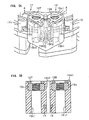
Fig. 3A is an enlarged perspective view showing a projected part which is projected toward a control board (a region encircled by a dotted line a inFig. 2 ) in the busbar integrated type insulator according to the embodiment of the invention, andFig. 3B is a sectional view taken along a line A-A inFig. 3A . -
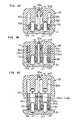
Figs. 4A to 4C shows a process chart showing a production process of the busbar integrated type insulator according to the embodiment of the invention, in whichFig. 4A is a view showing a fixed mold and a movable mold in a clamped state,Fig. 4B is a view showing molten resin filled in a cavity of the molds, andFig. 4C is a view showing a state where the fixed mold and the movable mold are opened after the molten resin has been hardened, and interposed pins fixed to the movable mold are removed. - Now, an embodiment of the invention will be described referring to the drawings.
As shown inFig. 1A , a busbar integratedtype insulator 14a in this embodiment is provided in an electric motor 1. This electric motor 1 is used in a motor-drivenoil pump 50 for supplementing oil pressure which is lowered during idle stop, in a transmission of an automobile, as shown inFig. 1A . - Referring to
Fig. 1A , the motor-drivenoil pump 50 integrally includes apump part 2 which sucks and discharges oil (fluid), and the electric motor 1 which drives thepump part 2 to rotate. Thispump part 2 is contained in apump chamber 24 which is formed by apump housing 20 in a shape of a bottomed tube and apump plate 23 for closing an end part of thepump housing 20. The electric motor 1 is contained in a motor housing 11 which is integrally formed with thepump housing 20 so as to communicate therewith: - The
aforesaid pump part 2 is a so-called trochoid pump, and includes anouter rotor 21 having internal teeth, and aninner rotor 22 having external teeth and meshed with theouter rotor 21. - As shown in
Figs. 1A and 1B , the aforesaid electric motor 1 includes a motor rotor 12 which is rotatably held in thepump housing 20 and the motor housing 11 respectively by means of a first and a second rolling bearings 4 and 5, astator core 13 in a tubular shape which surrounds the motor rotor 12, and six (a plurality of)coils 13b which are wound around thestator core 13. This electric motor 1 is a brushless DC motor having three phases. Three pairs of thecoils 13b which are opposed to one another constitute a U phase, a V phase, and a W phase. Amagnet 12a in a tubular shape is rigidly fitted to an outer periphery of the motor rotor 12, as shown inFig. 1A . - Referring to
Fig. 1A , in the motor-drivenoil pump 50 in this embodiment, acontrol board 9 for controlling the electric motor 1 is attached to the motor housing 11 at a side of a bottom part 11c of the motor housing 11. Thecontrol board 9 is contained and sealed in acontroller containing part 9b, together with electronic components 9a such as coils and condensers on its control circuit. - In the motor-driven
oil pump 50 in this embodiment, theinner rotor 22 is pivotally held by an end of the aforesaid motor rotor 12, whereby theinner rotor 22 is driven to rotate with the rotation of the motor rotor 12, thereby to suck and discharge the oil in cooperation with theouter rotor 21. - As shown in
Fig. 1A , the busbar integratedtype insulator 14a (the busbar structure) in this embodiment is fitted to thestator core 13 from a right side in an axial direction (from a side of the control board 9) in the aforesaid electric motor 1, and adapted to insulate thestator core 13 from theaforesaid coils 13b in cooperation with aninsulator 14b which is fitted to thestator core 13 from a left side in the axial direction. Theinsulators - The busbar integrated
type insulator 14a is formed in a tubular shape as a whole, as shown inFig. 1B andFig. 2 , and includes anannular part 15, and six (a plurality of) engagingparts 15a which are projected inward in a radial direction from theannular part 15 and adapted to be engaged withrespective teeth 13a of thestator core 13 corresponding to the three phases, namely the U phase, V phase and W phase, as described above. In this busbar integratedtype insulator 14a, four (a plurality of)busbars respective busbar terminals 16t to 19t which are connected to respective ends of thecoils 13b) are integrally molded with the aforesaid resin by in-mold molding, which is a kind of injection molding, in a state arranged at predetermined positions, for the purpose of electrically connecting thecoils 13b to one another, or electrically connecting thecoils 13b which constitute the three phases to theaforesaid control board 9. In this embodiment, each of thebusbars 16 to 19 is produced from a long-sized sheet member formed of metallic material (the sheet member of pure copper plated with tin) which is molded into a determined shape from a flat plate by folding or so. - Moreover, referring to
Figs. 1A, 1B andFig. 2 , four (a plurality of) projected parts 15pl to 15p4 are provided on theannular part 15 of the aforesaidbusbarintegrated type insulator 14a so as to project toward theaforesaid control board 9. In each of the projected parts 15p2 to 15p4, onenut 15n is embedded by in-mold molding, while in the projected part 15pl which is shown in an enlarged scale inFigs. 3A and 3B , the twonuts busbars bolts 100 are respectively screwed into thenuts 15n passing through the control board 9 (SeeFig. 1 ). In this manner, thecontrol board 9 is fixed to the busbar integratedtype insulator 14a at the aforesaid projected parts 15p1 to 15p4, and theaforesaid busbars 17 to 19 are electrically connected to the control circuit which is provided on the control board 9 (Thebusbar 16 functions as a common electrode, and not directly connected to the control circuit on the control board 9). In this manner, driving electric current which is controlled by the aforesaid control circuit is supplied to a pair of thecoils 13b which constitute the phases, U, V and W. More specifically, thebusbars 17 to 19 as shown inFig. 1B andFig. 2 are integrally provided with ring-like portions control board 9, the ring-like portions bolts 100 in a state where they are in face contact with one another, and consequently, theaforesaid coils 13b are electrically connected to the control circuit on thecontrol board 9 by way of therespective busbars 17 to 19. In the projected part 15pl as shown inFigs. 3A and 3B , a pair of thebolts 100 are screwed into the nuts 15n, in a state respectively passed through the through holes 15h1 which are formed through the projected part 15p1. - The busbar integrated
type insulator 14a in this embodiment is characterized in that on occasion of integrally molding a plurality of thebusbars 17 to 19 with PPS resin (the resin) by in-mold molding, a pair of interposed pins p1, p2 formed of rod-like members (SeeFigs. 4A to 4C ) are disposed in the mold so as to be interposed between theadjacent busbars type insulator 14a. Characteristic feature of the productionmethod will be described below, referring to a process for forming the above described projected part 15p1. - Specifically, as shown in
Fig. 4A , as a first step, thebusbars Fig. 2 ) in acavity 32c which is formed between a fixedmold 31 and amovable mold 32 which can be closed and opened with respect to the fixedmold 31, together with theother busbars 16, 19 (omitted inFig. 4A ). Thereafter, the twomolds - More specifically, the ring-
like portions aforesaid busbars mold 31 after inserting them over fixed pins pf, pf which are engaged and fixed at predetermined positions in the fixedmold 31. Thereafter, on occasion of clamping the twomolds engaged part 32a (a predetermined position) of themovable mold 32 in advance are moved together with themovable mold 32, and inserted into a region (a space) between thebusbars parts movable mold 32 so as to protrude toward the fixedmold 31 are engaged with the aforesaid fixed pins pf, pf, and distal end faces 32t of the protrudedparts 32s are butted against end faces of the nuts 15n at their inner diameter side, so that the molten resin may not intrude into the nuts 15n. - Then, as shown in
Fig. 4B ,molten resin 15r is filled into thecavity 32c in which thebusbars 16 to 19 have been arranged, from a plurality of gates which are not shown (resin filling step).
In this embodiment, the interposed pins p1, p2 are interposed between thebusbars busbars busbars mold 31 or resin pressure of themolten resin 15r which has been filled in thecavity 32c, resulting in electrical contact between them will be effectively prevented. - Thereafter, as shown in
Fig. 4C , themolten resin 15r which has been filled is hardened, and thebusbars 16 to 19 are fixed to the predetermined positions of a molded product with the hardened resin (SeeFig. 2 ). Thereafter, the aforesaid twomolds - In this embodiment, the interposed pins p1, p2 are moved along with movement of the
movable mold 32 when the twomolds type insulator 14a (SeeFig. 3B ). - Finally, the busbar integrated
type insulator 14a is removed from the fixedmold 31 to obtain a finished product.
As described above, according to the method of producing the busbar integratedtype insulator 14a (the busbar structure) in this embodiment, the following functions and advantages can be obtained. - (1) In this embodiment, on occasion of producing the busbar integrated
type insulator 14a by integrally molding a plurality of thebusbars 16 to 19 with the resin, the interposed pins p1, p2 to be interposed between thebusbars movable mold 32 for molding. As the results, such inconvenience that thebusbars busbars - (2) In this embodiment, the interposed pins p1, p2 are detachably disposed in the
engaged part 32a of themovable mold 32. Therefore, it is possible to dispose the interposed pins p1, p2 in themovable mold 32, when they are required for preventing electrical contact between thebusbars - (3) In this embodiment, when the
molds movable mold 32. As the results, the interposed pins p1, p2 will not remain in the obtained busbar integratedtype insulator 14a, and removal of the interposed pins p1, p2 from the molded product too can be easily and reliably performed. - (4) In this embodiment, the electric motor 1 is provided with the busbar integrated
type insulator 14a in which such inconvenience that thebusbars busbars - Further, the above described embodiment may be modified as follows.
In the above described embodiment, the interposed pins p1, p2 to be interposed between thebusbars movable mold 32 for molding. However, the interposed pins p1, p2 may be disposed in the fixedmold 31 alternatively, or may be disposed in both themolds - In the above described embodiment, the interposed pins p1, p2 are formed of a pair of rod-like members. However, the interposed pins p1, p2 may be formed of a pair of plate-like members. Alternatively, the pins do not have to be in a pair, but a single pin may be used.
In the above described embodiment, the interposed pins p1, p2 are disposed at one position in the movable mold 32 (the mold). However, the interposed pins p1, p2 to be interposed between the busbars which are arranged in close proximity to each other may be disposed at desired positions in the mold. For example, the interposed pins may be distributed to a plurality of positions in the mold. - In the above described embodiment, the electric motor 1 provided with the busbar integrated
type insulator 14a is used in the motor-drivenoil pump 50 for supplementing oil pressure which is lowered during idle stop, in a transmission of an automobile. However, it is of course possible to use this electric motor for other uses in an automobile, for example, as the electric motor for assisting steering motion of an electric power steering device, or for general-purpose other than the use in an automobile. - Further, technical concept which can be grasped from the above described embodiment and modifications will be described below.
In the transmission of an automobile, a motor-driven oil pump for supplementing oil pressure which is lowered during idle stop, wherein a pump part for sucking and discharging oil is integrally formed with an electric motor for rotating the pump part, characterized in that the electric motor as claimed in claim 5 is used as the aforesaid electric motor. According to this structure, electric performance of the electric motor in the motor-driven oil pump for supplementing the oil pressure which is lowered during idle stop is enhanced. As the results, reliability as themotor-driven oil pump for use in an automobile is enhanced.
Claims (6)
- A method of producing a busbar structure, the method comprising:arranging a plurality of busbars in close proximity to each other in a mold;interposing an interposed pin between the busbar; andintegrally molding the busbars with resin.
- The method according to claim 1, wherein the interposed pin is detachably disposed at a predetermined position in the mold.
- The method according to claim 1, wherein
in the arranging step, the busbars are arranged at predetermined position in a cavity which is formed between a fixed mold and a movable mold of the mold the movable mold being capable of being clamped and opened with respect to the fixed mold, and the fixed and movable molded are clamped,
in the molding step, moltenresin is filled into the cavity in which the busbars are arranged, and the molten resin is hardened to fix the busbars at predetermined positions with the hardened resin, and
when the fixed and movable molds are opening after the molten resin is hardened, the interposed pin is moved from the molded product. - A busbar structure comprising:a resin body;a plurality of busbars molded in the resin body, the busbars being arranged in close proximity to each other; anda through hole that is formed through the resin body and arranged between the busbars,wherein the through hole is formed by removing an interposed pin which is interposed between the busbars for preventing the busbars from being electrically contacted with each other at the time of molding the busbars with resin.
- An electric motor comprising:coils constituting phases;a rotor surrounded by a stator core around which the coils are wound; anda busbar integrated type insulator for insulating the stator core from the coils and relaying electrical connection to an external control circuit, the insulator includes a busbar structure according to claim 4.
- A pump comprising:a pump part which sucks and discharges fluid; andan electric motor according to claim 5 which drives the pump part to rotate.
Applications Claiming Priority (1)
| Application Number | Priority Date | Filing Date | Title |
|---|---|---|---|
| JP2007010396A JP4978208B2 (en) | 2007-01-19 | 2007-01-19 | Bus bar structure, method for manufacturing the bus bar structure, and electric motor having the bus bar structure |
Publications (2)
| Publication Number | Publication Date |
|---|---|
| EP1947754A1 true EP1947754A1 (en) | 2008-07-23 |
| EP1947754B1 EP1947754B1 (en) | 2016-11-30 |
Family
ID=39304746
Family Applications (1)
| Application Number | Title | Priority Date | Filing Date |
|---|---|---|---|
| EP08000881.6A Ceased EP1947754B1 (en) | 2007-01-19 | 2008-01-17 | Busbar structure, method of producing the busbar structure, and electric motor having the busbar structure |
Country Status (3)
| Country | Link |
|---|---|
| US (1) | US7861407B2 (en) |
| EP (1) | EP1947754B1 (en) |
| JP (1) | JP4978208B2 (en) |
Cited By (4)
| Publication number | Priority date | Publication date | Assignee | Title |
|---|---|---|---|---|
| EP1965485A3 (en) * | 2007-02-28 | 2010-01-06 | JTEKT Corporation | Electric motor and electric pump unit |
| WO2015000672A3 (en) * | 2013-07-03 | 2015-04-02 | Ebm-Papst St. Georgen Gmbh & Co. Kg | Electronically commuted motor |
| EP3355447A1 (en) * | 2017-01-31 | 2018-08-01 | Nidec Corporation | Motor and blower including the same |
| CN110311480A (en) * | 2018-03-27 | 2019-10-08 | 株式会社山田制作所 | Motor stator |
Families Citing this family (7)
| Publication number | Priority date | Publication date | Assignee | Title |
|---|---|---|---|---|
| JP4743167B2 (en) * | 2007-05-29 | 2011-08-10 | トヨタ自動車株式会社 | Terminal module for rotating electric machine and rotating electric machine |
| JP5332414B2 (en) * | 2008-09-02 | 2013-11-06 | 株式会社ジェイテクト | Electric motor unit |
| WO2013072948A1 (en) * | 2011-11-14 | 2013-05-23 | 三菱電機株式会社 | Pump, refrigeration cycle device, and method for manufacturing pump |
| CN105071600B (en) * | 2015-07-16 | 2017-12-29 | 博格思众(常州)电机电器有限公司 | A kind of location structure of pcb board and upper insulating support |
| DE102017106399B4 (en) * | 2017-03-24 | 2023-10-05 | Nidec Corporation | Electric motor |
| DE102017211168A1 (en) * | 2017-06-30 | 2019-01-03 | Zf Friedrichshafen Ag | Stator interconnection device for a rotating electrical machine |
| MY209053A (en) * | 2019-08-21 | 2025-06-18 | Panasonic Ip Man Co Ltd | Stator, and electric motor |
Citations (4)
| Publication number | Priority date | Publication date | Assignee | Title |
|---|---|---|---|---|
| DE3834673A1 (en) * | 1988-01-19 | 1989-08-03 | Olympus Optical Co | Air-core rotor and method for its production |
| WO2000057532A2 (en) * | 1999-03-19 | 2000-09-28 | Briggs & Stratton Corporation | Direct current motor |
| JP2005341640A (en) | 2004-05-24 | 2005-12-08 | Koyo Seiko Co Ltd | Stator of motor |
| US20070178723A1 (en) * | 2006-02-01 | 2007-08-02 | Nidec Corporation | Busbar Unit, Electric Motor and Electrohydraulic Power Steering System Furnished With the Busbar Unit, and Method of Manufacturing the Busbar Unit |
Family Cites Families (8)
| Publication number | Priority date | Publication date | Assignee | Title |
|---|---|---|---|---|
| JPH05291325A (en) * | 1992-04-08 | 1993-11-05 | Hitachi Ltd | Mold |
| JP3287532B2 (en) * | 1996-02-02 | 2002-06-04 | 矢崎総業株式会社 | Insert molding method |
| JP2001086695A (en) | 1999-09-16 | 2001-03-30 | Toyoda Mach Works Ltd | Motor |
| JP2001103700A (en) | 1999-09-30 | 2001-04-13 | Toyota Motor Corp | Motor stator |
| JP2003079079A (en) | 2001-09-03 | 2003-03-14 | Honda Motor Co Ltd | Power distribution ring for rotating electric machines |
| JP3772716B2 (en) * | 2001-09-28 | 2006-05-10 | 日立電線株式会社 | Molded terminal block and manufacturing method thereof |
| JP2004304874A (en) | 2003-03-28 | 2004-10-28 | Toyota Motor Corp | Bus bar module and method of manufacturing bus bar module |
| JP4404199B2 (en) | 2004-03-30 | 2010-01-27 | 株式会社ジェイテクト | Synchronous motor |
-
2007
- 2007-01-19 JP JP2007010396A patent/JP4978208B2/en not_active Expired - Fee Related
-
2008
- 2008-01-17 US US12/007,958 patent/US7861407B2/en not_active Expired - Fee Related
- 2008-01-17 EP EP08000881.6A patent/EP1947754B1/en not_active Ceased
Patent Citations (4)
| Publication number | Priority date | Publication date | Assignee | Title |
|---|---|---|---|---|
| DE3834673A1 (en) * | 1988-01-19 | 1989-08-03 | Olympus Optical Co | Air-core rotor and method for its production |
| WO2000057532A2 (en) * | 1999-03-19 | 2000-09-28 | Briggs & Stratton Corporation | Direct current motor |
| JP2005341640A (en) | 2004-05-24 | 2005-12-08 | Koyo Seiko Co Ltd | Stator of motor |
| US20070178723A1 (en) * | 2006-02-01 | 2007-08-02 | Nidec Corporation | Busbar Unit, Electric Motor and Electrohydraulic Power Steering System Furnished With the Busbar Unit, and Method of Manufacturing the Busbar Unit |
Cited By (9)
| Publication number | Priority date | Publication date | Assignee | Title |
|---|---|---|---|---|
| EP1965485A3 (en) * | 2007-02-28 | 2010-01-06 | JTEKT Corporation | Electric motor and electric pump unit |
| US8120216B2 (en) | 2007-02-28 | 2012-02-21 | Jtekt Corporation | Electric motor and electric pump unit with busbars integrally formed with driving circuit connecting terminals |
| WO2015000672A3 (en) * | 2013-07-03 | 2015-04-02 | Ebm-Papst St. Georgen Gmbh & Co. Kg | Electronically commuted motor |
| CN105359387A (en) * | 2013-07-03 | 2016-02-24 | 依必安-派特圣乔根有限责任两合公司 | Electronically commuted motor |
| CN105359387B (en) * | 2013-07-03 | 2018-06-19 | 依必安-派特圣乔根有限责任两合公司 | The motor of electronic rectifier |
| US10158267B2 (en) | 2013-07-03 | 2018-12-18 | Ebm-Papst St. Georgen Gmbh & Co. Kg | Electronically commutated motor |
| EP3355447A1 (en) * | 2017-01-31 | 2018-08-01 | Nidec Corporation | Motor and blower including the same |
| CN110311480A (en) * | 2018-03-27 | 2019-10-08 | 株式会社山田制作所 | Motor stator |
| CN110311480B (en) * | 2018-03-27 | 2023-03-28 | 株式会社山田制作所 | Stator for motor |
Also Published As
| Publication number | Publication date |
|---|---|
| JP4978208B2 (en) | 2012-07-18 |
| US7861407B2 (en) | 2011-01-04 |
| US20080175732A1 (en) | 2008-07-24 |
| EP1947754B1 (en) | 2016-11-30 |
| JP2008178252A (en) | 2008-07-31 |
Similar Documents
| Publication | Publication Date | Title |
|---|---|---|
| EP1947754B1 (en) | Busbar structure, method of producing the busbar structure, and electric motor having the busbar structure | |
| US9312737B2 (en) | Motor | |
| US7588444B2 (en) | Busbar unit, electric motor and electrohydraulic power steering system furnished with the busbar unit, and method of manufacturing the busbar unit | |
| CN111327142B (en) | Motor | |
| US10594173B2 (en) | Actuator with coated stator and rotor modules | |
| JP2013247761A (en) | Electric oil pump apparatus | |
| JP5363255B2 (en) | Stator manufacturing method and stator | |
| CN107000276B (en) | Insert-molded product and method for producing insert-molded product | |
| CN112567601B (en) | Motor, electric power steering device, method for manufacturing motor, bus bar unit, and method for manufacturing bus bar unit | |
| US20130285513A1 (en) | Control device and motor unit including control device | |
| US20180219449A1 (en) | Drive apparatus | |
| CN107660322B (en) | control device | |
| JP4623430B2 (en) | Busbar unit, electric motor, and busbar unit manufacturing method | |
| US20080219867A1 (en) | Electric motor and electric pump unit | |
| EP2680405A2 (en) | Motor | |
| JP4978359B2 (en) | Bus bar structure and electric motor having the bus bar structure | |
| JP2013150403A (en) | Motor device and manufacturing method therefor | |
| KR20170106629A (en) | Bus-bar of motor and motor having the same | |
| CN111313594A (en) | Drive device | |
| KR20120048319A (en) | Mold structure for bus-bar of eps motor | |
| JP6019733B2 (en) | Electric oil pump device | |
| KR20210095381A (en) | Motor | |
| JP2013238157A5 (en) | ||
| CN114552894A (en) | Driving device and electric product | |
| KR20130019091A (en) | Stator of motor |
Legal Events
| Date | Code | Title | Description |
|---|---|---|---|
| PUAI | Public reference made under article 153(3) epc to a published international application that has entered the european phase |
Free format text: ORIGINAL CODE: 0009012 |
|
| AK | Designated contracting states |
Kind code of ref document: A1 Designated state(s): AT BE BG CH CY CZ DE DK EE ES FI FR GB GR HR HU IE IS IT LI LT LU LV MC MT NL NO PL PT RO SE SI SK TR |
|
| AX | Request for extension of the european patent |
Extension state: AL BA MK RS |
|
| 17P | Request for examination filed |
Effective date: 20081021 |
|
| AKX | Designation fees paid |
Designated state(s): DE FR |
|
| 17Q | First examination report despatched |
Effective date: 20140319 |
|
| REG | Reference to a national code |
Ref country code: DE Ref legal event code: R079 Ref document number: 602008047596 Country of ref document: DE Free format text: PREVIOUS MAIN CLASS: H02K0003040000 Ipc: H02K0003520000 |
|
| RIC1 | Information provided on ipc code assigned before grant |
Ipc: H02K 11/00 20060101ALI20150427BHEP Ipc: H02K 3/52 20060101AFI20150427BHEP |
|
| GRAP | Despatch of communication of intention to grant a patent |
Free format text: ORIGINAL CODE: EPIDOSNIGR1 |
|
| INTG | Intention to grant announced |
Effective date: 20160713 |
|
| GRAS | Grant fee paid |
Free format text: ORIGINAL CODE: EPIDOSNIGR3 |
|
| GRAA | (expected) grant |
Free format text: ORIGINAL CODE: 0009210 |
|
| AK | Designated contracting states |
Kind code of ref document: B1 Designated state(s): DE FR |
|
| REG | Reference to a national code |
Ref country code: FR Ref legal event code: PLFP Year of fee payment: 10 |
|
| REG | Reference to a national code |
Ref country code: DE Ref legal event code: R096 Ref document number: 602008047596 Country of ref document: DE |
|
| REG | Reference to a national code |
Ref country code: DE Ref legal event code: R097 Ref document number: 602008047596 Country of ref document: DE |
|
| PLBE | No opposition filed within time limit |
Free format text: ORIGINAL CODE: 0009261 |
|
| STAA | Information on the status of an ep patent application or granted ep patent |
Free format text: STATUS: NO OPPOSITION FILED WITHIN TIME LIMIT |
|
| 26N | No opposition filed |
Effective date: 20170831 |
|
| REG | Reference to a national code |
Ref country code: FR Ref legal event code: PLFP Year of fee payment: 11 |
|
| PGFP | Annual fee paid to national office [announced via postgrant information from national office to epo] |
Ref country code: DE Payment date: 20200107 Year of fee payment: 13 |
|
| PGFP | Annual fee paid to national office [announced via postgrant information from national office to epo] |
Ref country code: FR Payment date: 20201210 Year of fee payment: 14 |
|
| REG | Reference to a national code |
Ref country code: DE Ref legal event code: R119 Ref document number: 602008047596 Country of ref document: DE |
|
| PG25 | Lapsed in a contracting state [announced via postgrant information from national office to epo] |
Ref country code: DE Free format text: LAPSE BECAUSE OF NON-PAYMENT OF DUE FEES Effective date: 20210803 |
|
| PG25 | Lapsed in a contracting state [announced via postgrant information from national office to epo] |
Ref country code: FR Free format text: LAPSE BECAUSE OF NON-PAYMENT OF DUE FEES Effective date: 20220131 |