EP1947531A2 - Vorrichtung zur Einstellung der Bewegungsamplitude der Einkupplungswippe eines Chronographs mit Säulenrad - Google Patents
Vorrichtung zur Einstellung der Bewegungsamplitude der Einkupplungswippe eines Chronographs mit Säulenrad Download PDFInfo
- Publication number
- EP1947531A2 EP1947531A2 EP07024464A EP07024464A EP1947531A2 EP 1947531 A2 EP1947531 A2 EP 1947531A2 EP 07024464 A EP07024464 A EP 07024464A EP 07024464 A EP07024464 A EP 07024464A EP 1947531 A2 EP1947531 A2 EP 1947531A2
- Authority
- EP
- European Patent Office
- Prior art keywords
- wheel
- chronograph
- cam
- column
- column wheel
- Prior art date
- Legal status (The legal status is an assumption and is not a legal conclusion. Google has not performed a legal analysis and makes no representation as to the accuracy of the status listed.)
- Granted
Links
Images



Classifications
-
- G—PHYSICS
- G04—HOROLOGY
- G04F—TIME-INTERVAL MEASURING
- G04F7/00—Apparatus for measuring unknown time intervals by non-electric means
- G04F7/04—Apparatus for measuring unknown time intervals by non-electric means using a mechanical oscillator
- G04F7/08—Watches or clocks with stop devices, e.g. chronograph
- G04F7/0842—Watches or clocks with stop devices, e.g. chronograph with start-stop control mechanisms
- G04F7/0847—Watches or clocks with stop devices, e.g. chronograph with start-stop control mechanisms with column wheel
-
- G—PHYSICS
- G04—HOROLOGY
- G04F—TIME-INTERVAL MEASURING
- G04F7/00—Apparatus for measuring unknown time intervals by non-electric means
- G04F7/04—Apparatus for measuring unknown time intervals by non-electric means using a mechanical oscillator
- G04F7/08—Watches or clocks with stop devices, e.g. chronograph
- G04F7/0823—Watches or clocks with stop devices, e.g. chronograph with couplings between the chronograph mechanism and the base movement
- G04F7/0828—Watches or clocks with stop devices, e.g. chronograph with couplings between the chronograph mechanism and the base movement acting in the plane of the movement
Definitions
- the present invention relates to a mechanical timepiece whose movement is provided with a chronograph mechanism comprising flip-flops and a column wheel as well as such a chronograph mechanism.
- the present invention relates to a chronograph mechanism comprising a column wheel controlling the movements of a clutch rocker provided with a particular adjustment device of the amplitude of displacement of the clutch rocker.
- This adjustment device determines more particularly the penetration of the toothing of an intermediate wheel, pivoted on the clutch rocker, in the toothing of the chronograph wheel. This penetration of the toothing of the intermediate wheel into the toothing of the chronograph wheel is decisive for the proper operation of the chronograph mechanism.
- the clutch rocker carrying the intermediate wheel is pivoted concentrically to a driving wheel engaged with the intermediate wheel.
- the spout, or free end, of the clutch rocker is in contact, under the effect of its return spring, with one of the columns of the column wheel, the column wheel the intermediate wheel does not mesh with the chronograph wheel.
- the toothing of the intermediate wheel engages in the toothing of the chronograph wheel to drive it.
- the degree of penetration of these teeth is essential despite the precision of these teeth due to small modules, manufacturing tolerances as well as poor round two wheels.
- This degree of penetration is determined by the position of an eccentric against which abuts the eccentric clutch lever located between the axis of rotation of the clutch rocker and the tip of this rocker.
- Such a displacement setting of the clutch rocker of a column wheel chronograph mechanism is known in particular from the document EP 1 316 869 or document CH 5821 .
- the object of the present invention is to provide a device for adjusting the penetration of the toothing of the intermediate wheel in the toothing of the chronograph wheel which is more precise.
- Another object of the present invention is to remove the eccentric adjusting the stroke of the clutch rocker to simplify the mechanism and its mounting. Indeed the eccentric being driven by a cone in a round hole, it requires a manual operation of setting up with a squared by the watchmaker.
- the invention relates to a device for adjusting the amplitude of the displacement of the clutch rocker of a column wheel chronograph mechanism, accurate and simpler than the devices described above and which is distinguished by the features listed in claim 1.
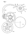
- the figure 1 illustrates the column wheel with its cap, the clutch rocker, the drive wheel, the intermediate wheel and the chronograph wheel of a chronograph mechanism in the disengaged or stopped position.
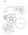
- the figure 2 is a view similar to the figure 1 but in the engaged or walking position of the chronograph, the column wheel being provided with its hat.
- the figure 3 illustrates on a larger scale the column wheel and the spout of the clutch rocker in the disengaged or stopping position of the chronograph, some parts being open for a better visibility of the mechanism.
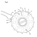
- the figure 4 is a figure similar to the figure 3 in the engaged or walking position of the chronograph.
- the figure 5 is a diametral section of the column wheel during the adjustment operation of the chronograph mechanism.
- the figure 6 is a diametral section of the column wheel provided with its cap, the nose of the clutch rocker being in abutment against a column.
- the figure 7 is a diametral section of the column wheel provided with its cap, the nose of the clutch rocker having fallen between two columns, the bearing face thereof being in abutment on the edge of the cap of the column wheel .
- the figure 8 is a cut similar to that of the figure 7 a variant of the adjustment device.
- the accompanying drawing illustrates the part of the chronograph mechanism making it possible to describe the adjustment device according to the invention of the amplitude of displacement of the clutch rocker or of the penetration of the toothing of the intermediate wheel into the toothing of the wheel. chronograph.
- the chronograph mechanism comprises, inter alia, a column wheel 1 comprising eight columns 2 uniformly distributed around its periphery and a wolf tooth 3 toothing comprising sixteen teeth.
- This column wheel is pivoted on an internally threaded hollow shaft 4 secured to the bridge 5.
- This column wheel 1 comprises a cap 6 resting on the hollow axis 4 and pivoted around it.
- a screw 7 screwed into the hollow shaft 4 makes it possible to lock the cap 6 of the column wheel 1.
- the peripheral part 17 of this cap 6 extending above the columns 2 of the column wheel also constitutes a limiting safety device. the axial displacement of the column wheel 1 in case of shocks.
- the column wheel 1 is driven stepwise in rotation by an unillustrated pawl engaged with the toothing 3, pawl controlled by a non-illustrated control lever actuated traditionally by an unillustrated pusher.
- the chronograph mechanism further comprises a clutch lever 10 pivoted about an axis 11 concentrically to a driving wheel 12 meshing permanently with an intermediate wheel 13 pivoted on a central portion of the clutch rocker 10. At its free end the clutch rocker 10 ends with a spout 14 cooperating with the column wheel 1. According to the angular position of the column wheel 1 the spout 14 takes bearing against the peripheral face of a column 2 of the column wheel or falls between two adjacent columns 2.
- the spout 14 has in its end portion 18 a smaller thickness than that of the rocker thereby forming a bearing surface 16.
- the peripheral surface 17 of the cap 6 of the wheel columns 1 is oval and not circular.
- the angular position of the cap 6 on the column wheel 1 determines the engaged angular position of the clutch rocker 10. To adjust this position simply unscrew slightly the fixing screw 7 of the cap 6 and move it angularly using a tool having fingers that are housed in holes 19 that includes the cap 6. Once the ideal position of the rocker 10 set the fastening screw 7 is tightened.
- the device for adjusting the stroke of the clutch rocker is constituted by the oval peripheral surface 17 of the cap 6 of the column wheel 1 cooperating with the bearing face 16 of the spout 14 of the rocker d clutch 10.
- the cap 6 thus has three functions, an aesthetic function, a function of limiting the axial displacements of the column wheel 1 in the event of shocks and a function of adjusting the penetration of the teeth of the intermediate wheels 13 and the chronograph 15.
- the mechanism is thus simplified by abandoning the eccentric generally used for adjusting the stroke of the clutch rocker.
- the adjustment of the stroke of the clutch rocker 10 is more precise because it is performed on the point of the clutch lever farthest from its pivot center, the displacement of the end of the spout 14 is greater amplitude than the displacement of the intermediate wheel which allows a very precise adjustment.
- the diameter of the cap 6 of the column wheel 1 is at least four to eight times greater than that of a usual control eccentric, it follows that the accuracy and visibility of the setting are greatly increased. This setting is also more progressive and therefore easier to perform.
- the ovalization of the cap 6 of the crown wheel is invisible to the naked eye, because the difference between the large and the small outer diameter is typically of the order of a few hundredths of a millimeter, for example 0.03 at 0.08 mm.
- the cap 6 of the column wheel 1 could have an off-center peripheral circumference rather than an equilibrium the result would be the even.
- a portion of the circumference of the cap has a distance to its center which varies according to its angular orientation so that said cap constitutes a cam for adjusting the position of the spout 14 of the latch. clutch when it is between two columns 2 of the column wheel 1.
- the cap 6 of the column wheel may have, seen from above, a circular shape but have on its underside an eccentric boss 21, the peripheral surface 22 serves as an adjustment cam cooperating with the bearing face 16 of the spout 14 clutch lever 10.
- the device for adjusting the penetration of the toothing of the intermediate wheel 13 into the toothing of the chronograph wheel 15 comprises on the one hand a bearing surface 16 carried by the spout 14 of the rocker d clutch and on the other hand a cam 17; 21,22 concentrically pivoted to the column wheel 1, preferably but not necessarily integrated in the cap 6 of the column wheel 1.
- This cam whose angular position determines the penetration of the toothing of the intermediate wheel 13 into the toothing of the chronograph wheel 15 is located at least partially above the column wheel, and can be fixed in the desired angular position, for example using a screw.
- This cam is preferably concentric with the column wheel 1 and in the preferred embodiment integrated in the cap 6 of this column wheel 1.
- the support face 16 of the spout 14 could be constituted by a pin driven into said spout 14.
Landscapes
- Physics & Mathematics (AREA)
- General Physics & Mathematics (AREA)
- Measurement Of Unknown Time Intervals (AREA)
Applications Claiming Priority (1)
| Application Number | Priority Date | Filing Date | Title |
|---|---|---|---|
| CH00085/07A CH703809B1 (fr) | 2007-01-22 | 2007-01-22 | Mécanisme de chronographe à roue à colonne et pièce d'horlogerie munie d'un tel mécanisme. |
Publications (3)
| Publication Number | Publication Date |
|---|---|
| EP1947531A2 true EP1947531A2 (de) | 2008-07-23 |
| EP1947531A3 EP1947531A3 (de) | 2011-05-25 |
| EP1947531B1 EP1947531B1 (de) | 2015-08-19 |
Family
ID=38984268
Family Applications (1)
| Application Number | Title | Priority Date | Filing Date |
|---|---|---|---|
| EP07024464.5A Active EP1947531B1 (de) | 2007-01-22 | 2007-12-18 | Vorrichtung zur Einstellung der Bewegungsamplitude der Einkupplungswippe eines Chronographs mit Säulenrad |
Country Status (2)
| Country | Link |
|---|---|
| EP (1) | EP1947531B1 (de) |
| CH (1) | CH703809B1 (de) |
Cited By (1)
| Publication number | Priority date | Publication date | Assignee | Title |
|---|---|---|---|---|
| EP2251747A3 (de) * | 2009-05-12 | 2016-12-07 | Patek Philippe SA Genève | Chronographenmechanismus und mit diesem Mechanismus ausgestattete Uhr |
Citations (2)
| Publication number | Priority date | Publication date | Assignee | Title |
|---|---|---|---|---|
| CH5821A (fr) | 1892-11-04 | 1893-03-31 | Lugrin Henry Alfred | Perfectionnement aux méchanismes de chronographes |
| EP1316869A2 (de) | 2001-12-03 | 2003-06-04 | Ortho-Clinical Diagnostics, Inc. | Verbesserungen einer Fluiddosiereinrichtung |
Family Cites Families (4)
| Publication number | Priority date | Publication date | Assignee | Title |
|---|---|---|---|---|
| FR806906A (fr) * | 1936-05-28 | 1936-12-29 | Leon Levy & Freres S A | Mécanisme de chronographe |
| CH209682A (fr) * | 1939-01-10 | 1940-04-30 | Hahn Charles | Chronographe-compteur. |
| EP1296205A1 (de) * | 2001-09-24 | 2003-03-26 | Girard-Perregaux S.A. | Chronographmechanismus |
| EP1316863A1 (de) * | 2001-11-09 | 2003-06-04 | Manufacture Roger Dubuis S.A. | Formuhrwerk mit Chronograph |
-
2007
- 2007-01-22 CH CH00085/07A patent/CH703809B1/fr unknown
- 2007-12-18 EP EP07024464.5A patent/EP1947531B1/de active Active
Patent Citations (2)
| Publication number | Priority date | Publication date | Assignee | Title |
|---|---|---|---|---|
| CH5821A (fr) | 1892-11-04 | 1893-03-31 | Lugrin Henry Alfred | Perfectionnement aux méchanismes de chronographes |
| EP1316869A2 (de) | 2001-12-03 | 2003-06-04 | Ortho-Clinical Diagnostics, Inc. | Verbesserungen einer Fluiddosiereinrichtung |
Cited By (1)
| Publication number | Priority date | Publication date | Assignee | Title |
|---|---|---|---|---|
| EP2251747A3 (de) * | 2009-05-12 | 2016-12-07 | Patek Philippe SA Genève | Chronographenmechanismus und mit diesem Mechanismus ausgestattete Uhr |
Also Published As
| Publication number | Publication date |
|---|---|
| EP1947531B1 (de) | 2015-08-19 |
| CH703809B1 (fr) | 2012-03-30 |
| EP1947531A3 (de) | 2011-05-25 |
Similar Documents
| Publication | Publication Date | Title |
|---|---|---|
| EP2718770B1 (de) | Vorrichtung zur ausrichtung der geschraubten aufzugskrone einer uhr | |
| EP2915012B1 (de) | Device for the orientation of a screwed element of a timepiece | |
| EP1927037B1 (de) | Vorrichtung zur befestigung eines bodens an einem uhrmittelteil | |
| EP1617305B1 (de) | Arretiervorrichtung bei der Zeigerstellung einer Uhr mit einem Tourbillon | |
| EP4194964B1 (de) | Unruh mit trägheitsregulierung | |
| EP1857892B1 (de) | Uhr mit einem drehbaren Teil | |
| EP2957964A2 (de) | Kippkupplung für uhren | |
| CH705087B1 (fr) | Pièce d'horlogerie. | |
| EP1701225B1 (de) | Geschraubte Krone für einer Uhr | |
| EP2196866A2 (de) | Assembly comprising a ratchet-wheel fixed to the barrel-arbor and barrel-arbor for this assembly | |
| CH714613A2 (fr) | Mouvement et pièce d'horlogerie. | |
| EP3462251B1 (de) | Stellmechanismus für uhrwerk | |
| EP1947531B1 (de) | Vorrichtung zur Einstellung der Bewegungsamplitude der Einkupplungswippe eines Chronographs mit Säulenrad | |
| EP3037896B1 (de) | Demontierbarer spiralklötzchenträger | |
| EP3339966B1 (de) | Drucktaste für eine uhr | |
| EP2010972B1 (de) | Uhr mit einem durch einen drehbaren aussenring gesteurten zeigereinstellmechanismus | |
| EP3391154B1 (de) | Schwingsystem für eine uhr | |
| EP4407382A1 (de) | Spiralfeder für uhrwerk | |
| EP3407142A1 (de) | Uhrwerk mit sekunden-stopp-funktion | |
| CH707158A2 (fr) | Elément vissé orientable, par exemple couronne pour pièce d'horlogerie. | |
| EP2500785B1 (de) | Uhrmechanismus und mit diesem Uhrmechanismus ausgestattete Uhr | |
| EP2035884B1 (de) | Bügel für brillen und brillen mit einem solchen bügel | |
| CH339132A (fr) | Montre munie d'une aiguille des secondes | |
| CH718095B1 (fr) | Montre comprenant un boîtier étanche logé dans une carrure extérieure. | |
| CH336014A (fr) | Ressort de friction |
Legal Events
| Date | Code | Title | Description |
|---|---|---|---|
| PUAI | Public reference made under article 153(3) epc to a published international application that has entered the european phase |
Free format text: ORIGINAL CODE: 0009012 |
|
| AK | Designated contracting states |
Kind code of ref document: A2 Designated state(s): AT BE BG CH CY CZ DE DK EE ES FI FR GB GR HU IE IS IT LI LT LU LV MC MT NL PL PT RO SE SI SK TR |
|
| AX | Request for extension of the european patent |
Extension state: AL BA HR MK RS |
|
| RAP1 | Party data changed (applicant data changed or rights of an application transferred) |
Owner name: PATEK PHILIPPE SA GENEVE |
|
| PUAL | Search report despatched |
Free format text: ORIGINAL CODE: 0009013 |
|
| AK | Designated contracting states |
Kind code of ref document: A3 Designated state(s): AT BE BG CH CY CZ DE DK EE ES FI FR GB GR HU IE IS IT LI LT LU LV MC MT NL PL PT RO SE SI SK TR |
|
| AX | Request for extension of the european patent |
Extension state: AL BA HR MK RS |
|
| 17P | Request for examination filed |
Effective date: 20110722 |
|
| AKX | Designation fees paid |
Designated state(s): CH DE FR GB IT LI |
|
| 17Q | First examination report despatched |
Effective date: 20150114 |
|
| GRAP | Despatch of communication of intention to grant a patent |
Free format text: ORIGINAL CODE: EPIDOSNIGR1 |
|
| INTG | Intention to grant announced |
Effective date: 20150414 |
|
| GRAS | Grant fee paid |
Free format text: ORIGINAL CODE: EPIDOSNIGR3 |
|
| GRAA | (expected) grant |
Free format text: ORIGINAL CODE: 0009210 |
|
| AK | Designated contracting states |
Kind code of ref document: B1 Designated state(s): CH DE FR GB IT LI |
|
| REG | Reference to a national code |
Ref country code: GB Ref legal event code: FG4D Free format text: NOT ENGLISH |
|
| REG | Reference to a national code |
Ref country code: CH Ref legal event code: NV Representative=s name: MICHELI AND CIE SA, CH Ref country code: CH Ref legal event code: EP |
|
| REG | Reference to a national code |
Ref country code: DE Ref legal event code: R096 Ref document number: 602007042631 Country of ref document: DE |
|
| REG | Reference to a national code |
Ref country code: FR Ref legal event code: PLFP Year of fee payment: 9 |
|
| REG | Reference to a national code |
Ref country code: DE Ref legal event code: R097 Ref document number: 602007042631 Country of ref document: DE |
|
| PLBE | No opposition filed within time limit |
Free format text: ORIGINAL CODE: 0009261 |
|
| STAA | Information on the status of an ep patent application or granted ep patent |
Free format text: STATUS: NO OPPOSITION FILED WITHIN TIME LIMIT |
|
| 26N | No opposition filed |
Effective date: 20160520 |
|
| REG | Reference to a national code |
Ref country code: FR Ref legal event code: PLFP Year of fee payment: 10 |
|
| REG | Reference to a national code |
Ref country code: FR Ref legal event code: PLFP Year of fee payment: 11 |
|
| PGFP | Annual fee paid to national office [announced via postgrant information from national office to epo] |
Ref country code: FR Payment date: 20221021 Year of fee payment: 16 |
|
| PGFP | Annual fee paid to national office [announced via postgrant information from national office to epo] |
Ref country code: IT Payment date: 20221111 Year of fee payment: 16 |
|
| P01 | Opt-out of the competence of the unified patent court (upc) registered |
Effective date: 20230521 |
|
| PG25 | Lapsed in a contracting state [announced via postgrant information from national office to epo] |
Ref country code: FR Free format text: LAPSE BECAUSE OF NON-PAYMENT OF DUE FEES Effective date: 20231231 |
|
| PG25 | Lapsed in a contracting state [announced via postgrant information from national office to epo] |
Ref country code: FR Free format text: LAPSE BECAUSE OF NON-PAYMENT OF DUE FEES Effective date: 20231231 |
|
| PG25 | Lapsed in a contracting state [announced via postgrant information from national office to epo] |
Ref country code: IT Free format text: LAPSE BECAUSE OF NON-PAYMENT OF DUE FEES Effective date: 20231218 |
|
| REG | Reference to a national code |
Ref country code: CH Ref legal event code: U11 Free format text: ST27 STATUS EVENT CODE: U-0-0-U10-U11 (AS PROVIDED BY THE NATIONAL OFFICE) Effective date: 20260101 |
|
| PGFP | Annual fee paid to national office [announced via postgrant information from national office to epo] |
Ref country code: DE Payment date: 20250930 Year of fee payment: 19 |
|
| PGFP | Annual fee paid to national office [announced via postgrant information from national office to epo] |
Ref country code: GB Payment date: 20251001 Year of fee payment: 19 |
|
| PGFP | Annual fee paid to national office [announced via postgrant information from national office to epo] |
Ref country code: CH Payment date: 20260101 Year of fee payment: 19 |