EP1947396A1 - Hot water supply system - Google Patents
Hot water supply system Download PDFInfo
- Publication number
- EP1947396A1 EP1947396A1 EP06811104A EP06811104A EP1947396A1 EP 1947396 A1 EP1947396 A1 EP 1947396A1 EP 06811104 A EP06811104 A EP 06811104A EP 06811104 A EP06811104 A EP 06811104A EP 1947396 A1 EP1947396 A1 EP 1947396A1
- Authority
- EP
- European Patent Office
- Prior art keywords
- water supply
- hot water
- liquid fluid
- supply system
- radiators
- Prior art date
- Legal status (The legal status is an assumption and is not a legal conclusion. Google has not performed a legal analysis and makes no representation as to the accuracy of the status listed.)
- Withdrawn
Links
Images




Classifications
-
- F—MECHANICAL ENGINEERING; LIGHTING; HEATING; WEAPONS; BLASTING
- F24—HEATING; RANGES; VENTILATING
- F24D—DOMESTIC- OR SPACE-HEATING SYSTEMS, e.g. CENTRAL HEATING SYSTEMS; DOMESTIC HOT-WATER SUPPLY SYSTEMS; ELEMENTS OR COMPONENTS THEREFOR
- F24D3/00—Hot-water central heating systems
- F24D3/18—Hot-water central heating systems using heat pumps
-
- F—MECHANICAL ENGINEERING; LIGHTING; HEATING; WEAPONS; BLASTING
- F24—HEATING; RANGES; VENTILATING
- F24D—DOMESTIC- OR SPACE-HEATING SYSTEMS, e.g. CENTRAL HEATING SYSTEMS; DOMESTIC HOT-WATER SUPPLY SYSTEMS; ELEMENTS OR COMPONENTS THEREFOR
- F24D17/00—Domestic hot-water supply systems
- F24D17/02—Domestic hot-water supply systems using heat pumps
-
- F—MECHANICAL ENGINEERING; LIGHTING; HEATING; WEAPONS; BLASTING
- F24—HEATING; RANGES; VENTILATING
- F24D—DOMESTIC- OR SPACE-HEATING SYSTEMS, e.g. CENTRAL HEATING SYSTEMS; DOMESTIC HOT-WATER SUPPLY SYSTEMS; ELEMENTS OR COMPONENTS THEREFOR
- F24D19/00—Details
- F24D19/10—Arrangement or mounting of control or safety devices
- F24D19/1006—Arrangement or mounting of control or safety devices for water heating systems
- F24D19/1051—Arrangement or mounting of control or safety devices for water heating systems for domestic hot water
- F24D19/1054—Arrangement or mounting of control or safety devices for water heating systems for domestic hot water the system uses a heat pump
-
- F—MECHANICAL ENGINEERING; LIGHTING; HEATING; WEAPONS; BLASTING
- F24—HEATING; RANGES; VENTILATING
- F24D—DOMESTIC- OR SPACE-HEATING SYSTEMS, e.g. CENTRAL HEATING SYSTEMS; DOMESTIC HOT-WATER SUPPLY SYSTEMS; ELEMENTS OR COMPONENTS THEREFOR
- F24D19/00—Details
- F24D19/10—Arrangement or mounting of control or safety devices
- F24D19/1006—Arrangement or mounting of control or safety devices for water heating systems
- F24D19/1051—Arrangement or mounting of control or safety devices for water heating systems for domestic hot water
- F24D19/1063—Arrangement or mounting of control or safety devices for water heating systems for domestic hot water counting of energy consumption
-
- F—MECHANICAL ENGINEERING; LIGHTING; HEATING; WEAPONS; BLASTING
- F24—HEATING; RANGES; VENTILATING
- F24D—DOMESTIC- OR SPACE-HEATING SYSTEMS, e.g. CENTRAL HEATING SYSTEMS; DOMESTIC HOT-WATER SUPPLY SYSTEMS; ELEMENTS OR COMPONENTS THEREFOR
- F24D3/00—Hot-water central heating systems
- F24D3/08—Hot-water central heating systems in combination with systems for domestic hot-water supply
-
- F—MECHANICAL ENGINEERING; LIGHTING; HEATING; WEAPONS; BLASTING
- F24—HEATING; RANGES; VENTILATING
- F24H—FLUID HEATERS, e.g. WATER OR AIR HEATERS, HAVING HEAT-GENERATING MEANS, e.g. HEAT PUMPS, IN GENERAL
- F24H15/00—Control of fluid heaters
- F24H15/10—Control of fluid heaters characterised by the purpose of the control
- F24H15/144—Measuring or calculating energy consumption
-
- F—MECHANICAL ENGINEERING; LIGHTING; HEATING; WEAPONS; BLASTING
- F24—HEATING; RANGES; VENTILATING
- F24H—FLUID HEATERS, e.g. WATER OR AIR HEATERS, HAVING HEAT-GENERATING MEANS, e.g. HEAT PUMPS, IN GENERAL
- F24H15/00—Control of fluid heaters
- F24H15/20—Control of fluid heaters characterised by control inputs
- F24H15/212—Temperature of the water
-
- F—MECHANICAL ENGINEERING; LIGHTING; HEATING; WEAPONS; BLASTING
- F24—HEATING; RANGES; VENTILATING
- F24H—FLUID HEATERS, e.g. WATER OR AIR HEATERS, HAVING HEAT-GENERATING MEANS, e.g. HEAT PUMPS, IN GENERAL
- F24H15/00—Control of fluid heaters
- F24H15/20—Control of fluid heaters characterised by control inputs
- F24H15/212—Temperature of the water
- F24H15/223—Temperature of the water in the water storage tank
-
- F—MECHANICAL ENGINEERING; LIGHTING; HEATING; WEAPONS; BLASTING
- F24—HEATING; RANGES; VENTILATING
- F24H—FLUID HEATERS, e.g. WATER OR AIR HEATERS, HAVING HEAT-GENERATING MEANS, e.g. HEAT PUMPS, IN GENERAL
- F24H15/00—Control of fluid heaters
- F24H15/20—Control of fluid heaters characterised by control inputs
- F24H15/238—Flow rate
-
- F—MECHANICAL ENGINEERING; LIGHTING; HEATING; WEAPONS; BLASTING
- F24—HEATING; RANGES; VENTILATING
- F24H—FLUID HEATERS, e.g. WATER OR AIR HEATERS, HAVING HEAT-GENERATING MEANS, e.g. HEAT PUMPS, IN GENERAL
- F24H15/00—Control of fluid heaters
- F24H15/20—Control of fluid heaters characterised by control inputs
- F24H15/246—Water level
- F24H15/248—Water level of water storage tanks
-
- F—MECHANICAL ENGINEERING; LIGHTING; HEATING; WEAPONS; BLASTING
- F24—HEATING; RANGES; VENTILATING
- F24H—FLUID HEATERS, e.g. WATER OR AIR HEATERS, HAVING HEAT-GENERATING MEANS, e.g. HEAT PUMPS, IN GENERAL
- F24H15/00—Control of fluid heaters
- F24H15/30—Control of fluid heaters characterised by control outputs; characterised by the components to be controlled
- F24H15/305—Control of valves
- F24H15/31—Control of valves of valves having only one inlet port and one outlet port, e.g. flow rate regulating valves
-
- F—MECHANICAL ENGINEERING; LIGHTING; HEATING; WEAPONS; BLASTING
- F24—HEATING; RANGES; VENTILATING
- F24H—FLUID HEATERS, e.g. WATER OR AIR HEATERS, HAVING HEAT-GENERATING MEANS, e.g. HEAT PUMPS, IN GENERAL
- F24H15/00—Control of fluid heaters
- F24H15/30—Control of fluid heaters characterised by control outputs; characterised by the components to be controlled
- F24H15/375—Control of heat pumps
- F24H15/38—Control of compressors of heat pumps
-
- F—MECHANICAL ENGINEERING; LIGHTING; HEATING; WEAPONS; BLASTING
- F24—HEATING; RANGES; VENTILATING
- F24H—FLUID HEATERS, e.g. WATER OR AIR HEATERS, HAVING HEAT-GENERATING MEANS, e.g. HEAT PUMPS, IN GENERAL
- F24H15/00—Control of fluid heaters
- F24H15/30—Control of fluid heaters characterised by control outputs; characterised by the components to be controlled
- F24H15/375—Control of heat pumps
- F24H15/385—Control of expansion valves of heat pumps
-
- F—MECHANICAL ENGINEERING; LIGHTING; HEATING; WEAPONS; BLASTING
- F24—HEATING; RANGES; VENTILATING
- F24H—FLUID HEATERS, e.g. WATER OR AIR HEATERS, HAVING HEAT-GENERATING MEANS, e.g. HEAT PUMPS, IN GENERAL
- F24H15/00—Control of fluid heaters
- F24H15/40—Control of fluid heaters characterised by the type of controllers
- F24H15/414—Control of fluid heaters characterised by the type of controllers using electronic processing, e.g. computer-based
- F24H15/443—Control of fluid heaters characterised by the type of controllers using electronic processing, e.g. computer-based using a central controller connected to several sub-controllers
-
- F—MECHANICAL ENGINEERING; LIGHTING; HEATING; WEAPONS; BLASTING
- F25—REFRIGERATION OR COOLING; COMBINED HEATING AND REFRIGERATION SYSTEMS; HEAT PUMP SYSTEMS; MANUFACTURE OR STORAGE OF ICE; LIQUEFACTION SOLIDIFICATION OF GASES
- F25B—REFRIGERATION MACHINES, PLANTS OR SYSTEMS; COMBINED HEATING AND REFRIGERATION SYSTEMS; HEAT PUMP SYSTEMS
- F25B6/00—Compression machines, plants or systems, with several condenser circuits
- F25B6/02—Compression machines, plants or systems, with several condenser circuits arranged in parallel
-
- F—MECHANICAL ENGINEERING; LIGHTING; HEATING; WEAPONS; BLASTING
- F24—HEATING; RANGES; VENTILATING
- F24D—DOMESTIC- OR SPACE-HEATING SYSTEMS, e.g. CENTRAL HEATING SYSTEMS; DOMESTIC HOT-WATER SUPPLY SYSTEMS; ELEMENTS OR COMPONENTS THEREFOR
- F24D2200/00—Heat sources or energy sources
- F24D2200/12—Heat pump
- F24D2200/123—Compression type heat pumps
-
- F—MECHANICAL ENGINEERING; LIGHTING; HEATING; WEAPONS; BLASTING
- F24—HEATING; RANGES; VENTILATING
- F24D—DOMESTIC- OR SPACE-HEATING SYSTEMS, e.g. CENTRAL HEATING SYSTEMS; DOMESTIC HOT-WATER SUPPLY SYSTEMS; ELEMENTS OR COMPONENTS THEREFOR
- F24D2200/00—Heat sources or energy sources
- F24D2200/32—Heat sources or energy sources involving multiple heat sources in combination or as alternative heat sources
-
- F—MECHANICAL ENGINEERING; LIGHTING; HEATING; WEAPONS; BLASTING
- F25—REFRIGERATION OR COOLING; COMBINED HEATING AND REFRIGERATION SYSTEMS; HEAT PUMP SYSTEMS; MANUFACTURE OR STORAGE OF ICE; LIQUEFACTION SOLIDIFICATION OF GASES
- F25B—REFRIGERATION MACHINES, PLANTS OR SYSTEMS; COMBINED HEATING AND REFRIGERATION SYSTEMS; HEAT PUMP SYSTEMS
- F25B2339/00—Details of evaporators; Details of condensers
- F25B2339/04—Details of condensers
- F25B2339/047—Water-cooled condensers
-
- Y—GENERAL TAGGING OF NEW TECHNOLOGICAL DEVELOPMENTS; GENERAL TAGGING OF CROSS-SECTIONAL TECHNOLOGIES SPANNING OVER SEVERAL SECTIONS OF THE IPC; TECHNICAL SUBJECTS COVERED BY FORMER USPC CROSS-REFERENCE ART COLLECTIONS [XRACs] AND DIGESTS
- Y02—TECHNOLOGIES OR APPLICATIONS FOR MITIGATION OR ADAPTATION AGAINST CLIMATE CHANGE
- Y02B—CLIMATE CHANGE MITIGATION TECHNOLOGIES RELATED TO BUILDINGS, e.g. HOUSING, HOUSE APPLIANCES OR RELATED END-USER APPLICATIONS
- Y02B30/00—Energy efficient heating, ventilation or air conditioning [HVAC]
- Y02B30/12—Hot water central heating systems using heat pumps
Definitions
- the present invention relates to a hot water supply system that utilizes heat pump type hot water supply machines.
- This hot water supply system 901 is, as shown in FIG. 8 , mainly configured by a central hot water supply machine 906, individual hot water supply machines 920 and water supply pipes 902, 911 and 914, and the like.
- the central hot water supply machine 906 is, as shown in FIG. 8 , mainly configured by a central hot water supply heat pump 907, a central hot water storage tank 908, a three-way valve 910 and a temperature sensor 912.
- the central hot water supply heat pump 907 is for heating tap water supplied through the upstream-most water supply pipe 902 to generate warm water.
- the central hot water storage tank 908 is for storing the warm water generated by the central hot water supply heat pump 907.
- the three-way valve 910 interconnects the central hot water storage tank 908, a branched pipe 905 that is branched at a first bifurcation point 904 from the upstream-most water supply pipe 902, and the constant temperature water supply pipe 911.
- the temperature sensor 912 is for measuring the temperature of the tap water or the warm water and is disposed downstream of the three-way valve 910.
- the individual hot water supply machines 920 are hot water supply machines disposed in dwelling units 950 in a multi-dwelling housing complex 960 and, as shown in FIG. 8 , are mainly configured by individual hot water supply heat pumps 921 and individual hot water storage tanks 922, respectively.
- the individual hot water supply heat pumps 921 are for further heating the warm water supplied through the individual water supply pipes 914 extending to the dwelling units 950 from second bifurcation points 913 of the constant temperature water supply pipe 911 to generate higher-temperature warm water (hot water).
- the individual hot water storage tanks 922 are for storing the high-temperature warm water (hot water) generated by the individual hot water supply heat pumps 921.
- hot water supply taps 924 are disposed downstream of the individual hot water storage tanks 922, and hot water supply openings 926 are disposed downstream thereof.
- the individual water supply pipes 914 are branched at third bifurcation points 916 upstream of the individual hot water supply heat pumps 921, water supply taps 930 are disposed downstream thereof, and water supply openings 932 are disposed downstream thereof.
- fourth bifurcation points 918 upstream of the water supply openings 930 and fifth bifurcation points 919 downstream of the hot water supply taps 924 are bypass-connected by bypass pipes 931 disposed with mixing taps 928.
- the central hot water supply heat pump 907 heats the tap water supplied from the upstream-most water supply pipe 902 to generate warm water of 5 to 65°C.
- This warm water is stored in the central hot water storage tank 908 and appropriately delivered on demand.
- the delivered warm water merges in the three-way valve 910 with tap water supplied from the branched pipe 905. Then, the water temperature after merging is sensed by the temperature sensor 912, and the mixing ratio is adjusted by the three-way valve 910 such that the temperature becomes 20°C.
- this warm water passes through the constant temperature water supply pipe 911 and the individual water supply pipes 914 and is diverted at the third bifurcation points 916, with some of the warm water being supplied to the individual hot water supply heat pumps 921 and the remaining warm water being supplied to the water supply taps 930.
- the individual hot water supply heat pumps 921 heat the warm water supplied through the individual water supply pipes 914 to generate warm water (hot water) of 20 to 90°C.
- This warm water (hot water) is stored in the individual hot water storage tanks 922 and appropriately delivered by opening the hot water supply taps 924.
- the delivered warm water (hot water) is supplied from the hot water openings 926. It will be noted that before that, it is mixed as needed by the mixing taps 928 that are simultaneously opened with warm water (hot water) that has been guided to the fourth bifurcation points 918, and temperature adjustment is performed.
- this hot water supply system 901 when installed in a multi-dwelling housing complex, residents of the dwelling units 950 can effectively utilize free space such as verandas.
- a hot water supply system pertaining to a first invention comprises a plurality of heat source units, first fluid pipes, second radiators, a second fluid pipe and a first liquid fluid storage container.
- Each of the heat source units includes a refrigerant circuit.
- the "radiators" mentioned here are condensers or gas coolers, for example.
- Each of the refrigerant circuits is formed by sequentially connecting a compressor, a first radiator, a pressure reducing mechanism and an evaporator.
- the first fluid pipes are disposed with respect to the first radiators. Additionally, a fluid that exchanges heat in the first radiators with refrigerant supplied from the compressors flows through these first fluid pipes.
- phase "fluid” mentioned here is a phrase that includes liquid fluids, gas fluids and supercritical fluids.
- heat exchange panels for floor heating, coil components of fan coil units, and hot water supply pipes for instantaneous water heating can be connected to these first fluid pipes.
- the second radiators are connected in parallel with respect to the first radiators to discharge sides of the compressors.
- a liquid fluid that exchanges heat in the second radiators with the refrigerant supplied from the compressors flows through the second fluid pipe.
- the first liquid fluid storage container is connected to the second fluid pipe. Additionally, the liquid fluid is stored in this first liquid fluid storage container.
- the plural heat source units include the refrigerant circuits that are formed by sequentially connecting the compressors, the first radiators, the pressure reducing mechanisms and the evaporators.
- the first fluid pipes are disposed with respect to the first radiators. Additionally, the liquid that exchanges heat in the first radiators with the refrigerant supplied from the compressors flows through these first fluid pipes.
- the second radiators are connected in parallel with respect to the first radiators to the discharge sides of the compressors. Additionally, the liquid fluid that exchanges heat in the second radiators with the refrigerant supplied from the compressors flows through this second fluid pipe.
- the first liquid fluid storage container is connected to the second fluid pipe. Additionally, the liquid fluid is stored in this first liquid fluid storage container.
- this hot water supply system when the heat source units are disposed in dwelling units of a multi-dwelling housing complex and the second radiators and the first liquid fluid storage container are installed on a roof or in an underground machine room of the multi-dwelling housing complex (when the liquid fluid storage container is installed in an underground machine room, a separate liquid fluid pump becomes necessary), not only are warm environments of the dwelling units supplied by just the heat source units installed in the dwelling units, but a shared hot water storage container can be held. In other words, in this hot water supply system, the heat source machine of the central hot water supply machine that had conventionally been installed becomes unnecessary. Consequently, in this hot water supply system, a repair reserve fund corresponding to the portion of the heat source machine and the like becomes unnecessary, and the economical burden on the residents of a condominium multi-dwelling housing complex becomes lighter.
- a hot water supply system pertaining to a second invention is the hot water supply system pertaining to the first invention and further comprises a central control device.
- the central control device centrally controls the plurality of heat source units.
- the central control device is disposed. For this reason, in this hot water supply system, it becomes possible to efficiently operate the plurality of heat source units as the situation demands and to store hot water in the first liquid fluid storage container.
- a hot water supply system pertaining to a third invention is the hot water supply system pertaining to the first invention or the second invention and further comprises flow rate control mechanisms.
- the flow rate control mechanisms control the flow rate of the refrigerant supplied from the compressors to the first radiators and the flow rate of the refrigerant supplied from the compressors to the second radiators.
- the "flow rate control mechanisms” mentioned here are valve mechanisms configured by electromagnetic valves whose openings are capable of being adjusted, for example.
- the phrase “flow rate control” mentioned here is a phrase that includes an aspect where the refrigerant discharged from the compressors is supplied to just the first radiators or to just the second radiators.
- the flow rate control mechanisms are disposed. For this reason, in this hot water supply system, it becomes possible to distribute the refrigerant discharged from the compressors freely to the first radiators and the second radiators. Consequently, in this hot water supply system, it becomes possible to freely adjust the heat quantity of the refrigerant in the first radiators and the heat quantity of the refrigerant in the second radiators.
- a hot water supply system pertaining to a fourth invention is the hot water supply system of any of the first invention to the third invention and further comprises heat exchangers.
- the heat exchangers are connected to the first fluid pipes. It will be noted that the "heat exchangers" mentioned here can be utilized for floor heating, air conditioning, or instantaneous water heating, for example.
- the heat exchangers are connected to the first fluid pipes. For this reason, in this hot water supply system, it becomes possible for the heat source units to provide not only the function of storing hot water in the shared first liquid fluid storage container in a multi-dwelling housing complex but also functions such as floor heating, air conditioning, and instantaneous water heating to each of the dwelling units.
- a hot water supply system pertaining to a fifth invention is the hot water supply system of any of the first invention to the fourth invention, wherein the first liquid fluid storage container is one.
- the "first liquid fluid storage container” mentioned here may be a water supply tank installed in a multi-dwelling housing complex such as an apartment complex.
- temperature irregularities are present in the liquid fluid, with low-temperature liquid fluid being present in the lower portion of the first liquid fluid storage container and high-temperature liquid fluid being present in the upper portion of the first liquid fluid storage container. Consequently, by ensuring that the low-temperature liquid fluid is delivered from the lower portion and that the high-temperature liquid fluid is delivered from the upper portion, the first liquid fluid storage container can function as a hot water supply-cum-water supply source.
- the first liquid fluid storage container is one. For this reason, in this hot water supply system, it becomes possible to reduce costs corresponding to the container for storing the liquid fluid.
- a hot water supply system pertaining to a sixth invention is the hot water supply system pertaining to the fifth invention, wherein one of the second fluid pipe is disposed with respect to a plurality of the second radiators.
- one of the second fluid pipe is disposed with respect to a plurality of the second radiators. For this reason, in this hot water supply system, it becomes possible to make the leading-out of the second fluid pipe simple.
- a hot water supply system pertaining to a seventh invention is the hot water supply system pertaining to the fifth invention or the sixth invention and further comprises a plurality of liquid fluid delivery pipes.
- the liquid fluid delivery pipes extend from the first liquid fluid storage container.
- the plurality of liquid fluid delivery pipes are disposed. For this reason, in this hot water supply system, it becomes possible to distribute the high-temperature liquid fluid stored in the first liquid fluid storage container to each dwelling unit of a multi-dwelling housing complex.
- a hot water supply system pertaining to an eighth invention is the hot water supply system pertaining to any of the first invention to the fourth invention, wherein a plurality of the first liquid fluid storage containers are disposed, and the first liquid fluid storage containers are interconnected by communicating pipes such that the first liquid fluid storage containers are capable of exchanging the liquid fluid.
- this hot water supply system a plurality of the first liquid fluid storage containers are disposed. For this reason, in this hot water supply system, it becomes possible to store liquid fluid of different temperatures in each of the first liquid fluid storage containers, for example. Further, in this hot water supply system, even when the liquid fluid in one of the first liquid fluid storage containers is centrally used, the liquid fluid in another of the first liquid fluid storage containers can be immediately compensated.
- a hot water supply system pertaining to a ninth invention is the hot water supply system pertaining to the eighth invention and further comprises a plurality of liquid fluid delivery pipes.
- the liquid fluid delivery pipes extend from the first liquid fluid storage containers.
- the plurality of liquid fluid delivery pipes are disposed with respect to the first liquid fluid storage containers. For this reason, in this hot water supply system, it becomes possible to immediately distribute the liquid fluid of various temperatures stored in the plurality of first liquid fluid storage containers to each dwelling unit of a multi-dwelling housing complex.
- a hot water supply system pertaining to a tenth invention is the hot water supply system pertaining to the seventh invention or the ninth invention and further comprises second liquid fluid storage containers.
- the second liquid fluid storage containers are disposed in the vicinities of the heat source units. Additionally, the liquid fluid delivered from the first liquid fluid storage containers via the liquid fluid delivery pipes is stored in these second liquid fluid storage containers.
- the second liquid fluid storage containers are disposed. For this reason, in this hot water supply system, for example, it becomes possible to store a relatively low-temperature liquid fluid in the first liquid fluid storage containers, further heat that liquid fluid in the first radiators after that liquid fluid has been supplied to the second liquid fluid storage containers, and generate a high-temperature liquid fluid. Consequently, in this hot water supply system, it becomes possible to hold liquid fluid of a desired temperature in each dwelling unit.
- a hot water supply system pertaining to an eleventh invention is the hot water supply system of any of the seventh invention, the ninth invention and the tenth invention and further comprises flow rate measuring means and temperature measuring means.
- the flow rate measuring means measure the flow rate of the liquid fluid flowing in the liquid fluid delivery pipes.
- the temperature measuring means measure the temperature of the liquid fluid flowing in the liquid fluid delivery pipes.
- the flow rate measuring means measure the flow rate of the liquid fluid flowing in the liquid fluid delivery pipes. Further, the temperature measuring means measure the temperature of the liquid fluid flowing in the liquid fluid delivery pipes. For this reason, in this hot water supply system, reasonable fee management can be performed in a multi-dwelling housing complex.
- a hot water supply system pertaining to a twelfth invention is the hot water supply system pertaining to any of the first invention to the eleventh invention and further comprises energy measuring means.
- the energy measuring means measure the amount of consumed energy of the heat source units for supplying the refrigerant to the second radiators.
- the energy measuring means measure the amount of consumed energy of the compressor for supplying the refrigerant to the second radiators. For this reason, in this hot water supply system, the contribution percentage of each of the heat source units with respect to heating the liquid fluid stored in the first liquid fluid storage container can be determined. As a result, it becomes possible to perform distribution of electrical bills corresponding to the contribution percentage of each of the heat source units in a multi-dwelling housing complex.
- the hot water supply system pertaining to the first invention when the heat source units are disposed in dwelling units of a multi-dwelling housing complex and the second radiators and the first liquid fluid storage container are installed on a roof or in an underground machine room of the multi-dwelling housing complex, not only are warm environments of the dwelling units supplied by just the heat source units installed in the dwelling units, but a shared hot water storage container can be held.
- the heat source machine of the central hot water supply machine that had conventionally been installed becomes unnecessary. Consequently, in this hot water supply system, a repair reserve fund corresponding to the portion of the heat source machine and the like becomes unnecessary, and the economical burden on the residents of a condominium multi-dwelling housing complex becomes lighter.
- the hot water supply system pertaining to the second invention it becomes possible to efficiently operate the plurality of heat source units as the situation demands and to store hot water in the first liquid fluid storage container.
- the hot water supply system pertaining to the third invention it becomes possible to freely adjust the heat quantity of the refrigerant in the first radiators and the heat quantity of the refrigerant in the second radiators.
- the heat source units In the hot water supply system pertaining to the fourth invention, it becomes possible for the heat source units to provide not only the function of storing hot water in the shared first liquid fluid storage container in a multi-dwelling housing complex but also functions such as floor heating, air conditioning, and instantaneous water heating to each of the dwelling units.
- the hot water supply system pertaining to the seventh invention it becomes possible to distribute the high-temperature liquid fluid stored in the first liquid fluid storage container to each dwelling unit of a multi-dwelling housing complex.
- the hot water supply system pertaining to the eighth invention it becomes possible to store liquid fluid of different temperatures in each of the first liquid fluid storage containers, for example. Further, in this hot water supply system, even when the liquid fluid in one of the first liquid fluid storage containers is centrally used, the liquid fluid in another of the first liquid fluid storage containers can be immediately compensated.
- the hot water supply system pertaining to the ninth invention it becomes possible to immediately distribute the liquid fluid of various temperatures stored in the plurality of first liquid fluid storage containers to each dwelling unit of a multi-dwelling housing complex.
- the hot water supply system pertaining to the tenth invention it becomes possible to store a relatively low-temperature liquid fluid in the first liquid fluid storage containers, further heat that liquid fluid in the first radiators after that liquid fluid has been supplied to the second liquid fluid storage containers, and generate a high-temperature liquid fluid. Consequently, in this hot water supply system, it becomes possible to hold liquid fluid of a desired temperature in each dwelling unit.
- the contribution percentage of each of the heat source units with respect to heating the liquid fluid stored in the first liquid fluid storage container can be determined. As a result, it becomes possible to perform distribution of electrical bills corresponding to the contribution percentage of each of the heat source units in a multi-dwelling housing complex.
- FIG. 1 a hot water supply system 1 pertaining to a first embodiment of the present invention will be described using the drawings of FIG. 1 to FIG. 4 .
- the hot water supply system 1 is a hot water supply system for a multi-dwelling housing complex and, as shown in FIG. 1 , is mainly configured by heat source units 10a, 10b, ..., 10z, floor heating units 50a, 50b, ..., 50z, a water heating unit 70, a water supply/hot water supply tank 80, a first water pump 81, a first water supply main 90, a second water supply main 91, water supply branched pipes 95a, 95b, ..., 95z, a hot water supply main 92, hot water supply branched pipes 94a, 94b, ..., 94z, a second water pump 93, individual management units 28a (see FIG. 3 ) and a central management unit 101 (see FIG. 4 ).
- the heat source units 10a, 10b, ..., 10z are so-called heat pump type heat source units and are installed on verandas or balconies of dwelling units 2a, 2b, ..., 2z of a multi-dwelling housing complex.
- the plural heat source units are represented by the reference numerals 10a, 10b, ..., 10z. It will be noted that because they all have the same configuration and specification, the heat source units will be described below using the heat source unit of reference numeral 10a as a representative.
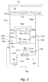
- the heat source unit 10a is, as shown in FIG. 2 , mainly disposed with a refrigerant circuit 20a that is formed as a result of a compressor 11a, a flow path switching unit 19a, a first water heat exchanger 15a, an electrically powered expansion valve 14a, an air heat exchanger 13a and an accumulator 12a being sequentially connected by a first refrigerant pipe 21a.
- the compressor 11a is a positive displacement inverter type compressor and becomes a drive source that compresses gaseous CO 2 (carbon dioxide) refrigerant filling the inside of the refrigerant circuit 20a and causes the refrigerant to circulate inside the refrigerant circuit 20a.
- CO 2 carbon dioxide
- the CO 2 refrigerant is controlled to reach a supercritical pressure on a high pressure side.
- the flow path switching unit 19a is, as shown in FIG. 2 , disposed on a discharge side of the compressor 11a and mainly includes one inlet and two outlets.
- a refrigerant passage extending from the inlet is branched midway and connected to inlet sides of a first electromagnetic valve 17a and a second electromagnetic valve 18a.
- an outlet side of the first electromagnetic valve 17a is connected to the first water heat exchanger 15a via the refrigerant passage and the first refrigerant pipe 21a, and an outlet side of the second electromagnetic valve 18a is connected to a first close valve 26a via the refrigerant passage and a first branched refrigerant pipe 22a.
- the second electromagnetic valve 18a is closed when the first electromagnetic valve 17a is open, and the first electromagnetic valve 17a is closed when the second electromagnetic valve 18a is open.
- the first water heat exchanger 15a is mainly disposed with a first water jacket and a second refrigerant pipe that is disposed inside the first water jacket and folded back several times.
- this first water heat exchanger 15a water or warm water flowing into the first water jacket from a first water pipe 24a exchanges heat with high-temperature supercritical refrigerant flowing into the second refrigerant pipe from the first refrigerant pipe 21 a and becomes high-temperature warm water (hot water), and, at the same time, the supercritical refrigerant flowing through the second refrigerant pipe is cooled.
- the high-temperature warm water (hot water) leaving the first water jacket thereafter flows into a second water pipe 25a.
- the supercritical refrigerant that has been cooled in the first water heat exchanger 15a is depressurized.
- the supercritical refrigerant that has been depressurized by the electrically powered expansion valve 14a exchanges heat with air blown by a fan 30a and becomes gas refrigerant, and, at the same time, that air is cooled.
- the fan 30a is, as shown in FIG. 2 , mainly configured by an impeller 31a and a fan motor 32a, and the fan 30a exhibits a blowing function as a result of the impeller 31a being driven to rotate by the fan motor 32a.
- the accumulator 12a is a compressor protector for ensuring that liquid refrigerant does not enter the compressor 11 a, and the accumulator 12a is disposed between an outlet side of the air heat exchanger 13a and a suction side of the compressor 11a. Additionally, the gas refrigerant passing through the accumulator 12a is sucked into the compressor 11 a.
- a second branched refrigerant pipe 23a is branched and extends from the first refrigerant pipe 21 a that interconnects an outlet side of the first water heat exchanger 15a and the electrically powered expansion valve 14a, and the second branched refrigerant pipe 23a is connected to a second close valve 27a.
- a third water pump 16a is disposed in this heat source unit 10a. Further, the third water pump 16a becomes a drive source that delivers water or warm water flowing through the first water pipe 24a to the first water heat exchanger 15a and a heat exchange panel 51a (described later) of the floor heating unit 50a.
- the floor heating units 50a, 50b, ..., 50z are installed in floor surfaces or the like of rooms of the dwelling units 2a, 2b, ..., 2z of the multi-dwelling housing complex.
- the plural floor heating units are represented by the reference numerals 50a, 50b, ..., 50z. It will be noted that because they all have the same configuration and specification, the floor heating units will be described below using the floor heating unit of reference numeral 50a as a representative.
- the floor heating unit 50a is, as shown in FIG. 2 , mainly disposed with a third water pipe 52a, a fourth water pipe 53a, and a heat exchange panel 51a.
- the third water pipe 52a is, as shown in FIG. 2 , connected to the second water pipe 25a of the heat source unit 10a via a first communication-use water pipe 41a.
- the fourth water pipe 53a is, as shown in FIG. 2 , connected to the first water pipe 24a of the heat source unit 10a via a second communication-use water pipe 42a.
- the heat exchange panel 51a is, as shown in FIG. 2 , connected to the third water pipe 52a and the fourth water pipe 53a and warms the floor of the room by warm water flowing inside the heat exchange panel 51 a.
- the water or warm water delivered from the heat exchange panel 51a flows through the fourth water pipe 53a and the second communication-use water pipe 42a, again flows into the first water pipe 24a of the heat source unit 10a, and is warmed by the first water heat exchanger 15a. It will be noted that the flow of this water or warm water is generated by the third water pump 16a of the heat source unit 10a (refer to the arrows in FIG. 2 ).
- the water heating unit 70 is a unit for heating the water or warm water stored in the water supply/hot water supply tank 80 to generate high-temperature warm water (hot water) and is installed on a roof of the multi-dwelling housing complex.
- This water heating unit 70 is disposed with third refrigerant pipes 73a, 73b, ..., 73z, fourth refrigerant pipes 74a, 74b, ..., 74z, second water heat exchangers 71a, 71b, ..., 71z, and a fifth water pipe 72.
- the third refrigerant pipes 73a, 73b, ..., 73z are connected to the first close valves 26a, 26b, ..., 26z of the heat source units 10a, 10b, ..., 10z via first communication-use refrigerant pipes 61 a, 61b,..., 61z, and are connected to the second water heat exchangers 71a, 71b, ..., 71z.
- the fourth refrigerant pipes 74a, 74b, ..., 74z are connected to the second close valves 27a, 27b, ..., 27z of the heat source units 10a, 10b, ..., 10z via second communication-use refrigerant pipes 62a, 62b, ..., 62z, and are connected to the second water heat exchangers 71 a, 71b, ..., 71 z.
- the second water heat exchangers 71a, 71b, ..., 71z are mainly disposed with second water jackets and fifth refrigerant pipes that are disposed inside the second water jackets and folded back several times.
- water or warm water that is delivered by the first water pump 81 from the water supply/hot water supply tank 80 passes through the fifth water pipe 72 and flows into the second water jackets exchanges heat with high-temperature supercritical refrigerant flowing into the fifth refrigerant pipes and becomes high-temperature warm water, and, at the same time, the supercritical refrigerant flowing through the fifth refrigerant pipes is cooled.
- the high-temperature warm water leaving the second water jackets is thereafter returned to the water supply/hot water supply tank 80 through a seventh water pipe 83 (refer to the arrows in FIG. 2 ).
- the water supply/hot water supply tank 80 is a tank that simultaneously stores water and high-temperature warm water (hot water) and is installed on the roof of the multi-dwelling housing complex.
- the water supply/hot water supply tank 80 simultaneously stores water and high-temperature warm water (hot water) is attributed to the fact that temperature irregularities arise in liquid fluid inside a first liquid fluid storage container, with low-temperature liquid fluid being present in the lower portion of the first liquid fluid storage container and high-temperature liquid fluid being present in the upper portion of the first liquid fluid storage container.
- the first water pump 81 is connected to the water supply/hot water supply tank 80 via an eighth water pipe 82 and plays the role of delivering the water and warm water (hot water) stored in the water supply/hot water supply tank 80 to the fifth water pipe 72 of the water heating unit 70.
- the first water supply main 90 is a water supply pipe that extends from a waterworks pipe (not shown) buried underground to the water supply/hot water supply tank 80 installed on the roof of the multi-dwelling housing complex. It will be noted that the water supplied from the waterworks pipe is supplied to the water supply/hot water supply tank 80 by a pump (not shown) disposed midway in the first water supply main 90.
- the second water supply main 91 is a water supply pipe that becomes the backbone for supplying water to each of the dwelling units 2a, 2b, ..., 2z of the multi-dwelling housing complex, is connected to the lower portion of the water supply/hot water supply tank 80, and runs through the inside of the building frame of the multi-dwelling housing complex.
- the water supply branched pipes 95a, 95b, ..., 95z are water supply pipes that are branched from the second water supply main 91 and extend to the dwelling units 2a, 2b, ..., 2z of the multi-dwelling housing complex. Further, first manual valves 97a, 97b, ..., 97z are disposed on terminal ends of these water supply branched pipes 95a, 95b, ..., 95z. It will be noted that these first manual valves 97a, 97b, ..., 97z are opened and closed in response to the will of the residents of the dwelling units 2a, 2b, ..., 2z. Further, unillustrated water meters are connected to these water supply branched pipes 95a, 95b, ..., 95z.
- the hot water supply main 92 is a hot water supply pipe that becomes the backbone for supplying hot water to each of the dwelling units 2a, 2b, ..., 2z of the multi-dwelling housing complex, runs through the inside of the building frame of the multi-dwelling housing complex from the upper portion of the water supply/hot water supply tank 80, and again returns to the water supply/hot water supply tank 80.
- the hot water supply branched pipes 94a, 94b, ..., 94z are hot water supply pipes that are branched from the hot water supply main 92 and extend to the dwelling units 2a, 2b, ..., 2z of the multi-dwelling housing complex. Further, second manual valves 96a, 96b, ..., 96z are disposed on terminal ends of these hot water supply branched pipes 94a, 94b, ..., 94z. It will be noted that these second manual valves 96a, 96b, ..., 96z are opened and closed in response to the will of the residents of the dwelling units 2a, 2b, ..., 2z.
- temperature sensors 98a, 98b, ..., 98z and flowmeters 99a, 99b, ..., 99z are attached to these hot water supply branched pipes 94a, 94b, ..., 94z. It will be noted that these temperature sensors 98a, 98b, ..., 98z and flowmeters 99a, 99b, ..., 99z are communicably connected to the central management unit 101 such that how much hot water of what °C the residents of each of the dwelling units 2a, 2b, ..., 2z have used can be understood.
- the second water pump 93 is disposed in the hot water supply main 92 downstream of the bifurcation point of the hot water supply branched pipe 94a and becomes a drive source that again returns the hot water flowing in the hot water supply main 92 to the water supply/hot water supply tank 80.
- the individual management units 28a are installed on a wall surface or the like of a room in each of the dwelling units 2a, 2b, ..., 2z of the multi-dwelling housing complex.
- the individual management units installed in the dwelling units 2a, 2b, ..., 2z all have the same configuration and specification, so the individual management units will be described below using the individual management unit for the floor heating unit represented by reference numeral 50a as a representative.
- the individual management unit 28a controls the heat source unit 10a, 10b, ..., 10z in response to the demands of the residents of the dwelling unit 2a, 2b, ..., 2z or in accordance with a command from the central management unit 101, collect necessary data from the heat source unit 10a, 10b, ..., 10z, and transmit the data to the central management unit 101.
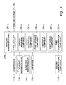
- the individual management units 28a is mainly configured by a first control component 281a, an energy measuring component 282a, a switch determining component 283a, a first storage component 284a, a first input component 286a, a first display component 287a and a first communication component 285a.
- the first control component 281a is electrically connected to the compressor 11a, the electrically powered expansion valve 14a, the flow path switching unit 19a, the fan motor 32a and the third water pump 16a via a dedicated interface (not shown) and controls each of the devices 11 a, 14a, 16a, 19a and 32a in accordance with an individual control program stored in the first storage component 284a.
- the energy measuring component 282a is communicably connected to the compressor 11a, the electrically powered expansion valve 14a, the flow path switching unit 19a and the fan motor 32a via a dedicated interface (not shown) and measures the quantity of electrical energy that each of the devices 11a, 14a, 19a and 32a consumes when the second electromagnetic valve 18a is in an open state.
- the switch determining component 283a is electrically connected to the flow path switching unit 19a and switches between opened and closed states of the first electromagnetic valve 17a and the second electromagnetic valve 18a in response to the demands of the residents of the dwelling unit 2a, 2b, ..., 2z or in accordance with a command from the central management unit 101.
- the first storage component 284a are stored programs such as the aforementioned individual control program and a communication program, and data necessary for performing control and communication.
- a floor heating ON/OFF button, a temperature adjustment button, and the like are disposed in the first input component 286a, and when those buttons are pressed by residents or the like of the dwelling unit 2a, 2b, ..., 2z, starting/stopping and positive displacement control of the compressor 11a of the heat source unit 10a, 10b, ..., 10z, control of the opening of the electrically powered expansion valve 14a, and status switching of the flow path switching unit 19a are performed.
- the first display component 287a displays the start/stop status of floor heating, the set temperature, the operating area, and whether or not the heat source unit 10a, 10b, ..., 10z are being centrally controlled.
- the first communication component 285a is communicable with a second communication component 105 of the central management unit 101, transmits status data and energy measurement data of the heat source unit 10a, 10b, ..., 10z to the central management unit 101, and receives control signals and the like transmitted from the central management unit 101.
- the central management unit 101 is installed in a management room, a machine room, or the like of the multi-dwelling housing complex.
- This central management unit 101 is for centrally managing the heat source units 10a, 10b, ..., 10z installed in the dwelling units 2a, 2b, ..., 2z and, as shown in FIG. 4 , is mainly configured by a second control component 102, a fee deriving component 103, a second storage component 104 and a second communication component 105.
- the second control component 102 is electrically connected to the first water pump 81 via a dedicated interface (not shown), controls the first water pump 81 in accordance with a central control program stored in the second storage component 104, generates control signals for centrally controlling the plural heat source units 10a, 10b, ..., 10z, and transmits the control signals to the first communication components 285a, 285b, ..., 285z of the individual management units 28a through the second communication component 105.
- the fee deriving component 103 is communicably connected to the temperature sensors 98a, 98b, ..., 98z and the flowmeters 99a, 99b, ..., 99z via a dedicated interface (not shown) and derives hot water supply fees in regard to each of the dwelling units 2a, 2b, ..., 2z in accordance with a fee derivation program stored in the second storage component 104.
- methods of deriving the hot water supply fees include a method of deriving the hot water supply fees by checking temperature data and use flow rate data against a fee management table, for example.
- this fee deriving component 103 calculates the contribution percentage of each of the heat source units 10a, 10b, ..., 10z to heating the water or warm water stored in the water supply/hot water supply tank 80 by utilizing the energy measurement data transmitted from the first communication components 285a, 285b, ..., 285z to determine reduced fees. Examples of methods of calculating these reduced fees include a method of multiplying the electrical power unit price by the sum of the energy measurement data and then multiplying the contribution percentage of each of the heat source unites 10a, 10b, ..., 10z.
- the second storage component 104 are stored programs such as the aforementioned central control program and fee derivation program, history data such as temperature data, use flow rate data and energy measurement data, and a fee management table.
- the second communication component 105 is communicable with the first communication components 285a, 285b, ..., 285c of the plural individual management units 28a, transmits control signals and the like generated by the second control component 102 to the individual management units 28a, and receives status data and energy measurement data of the heat source units transmitted from the first communication components 285a, 285b, ..., 285z of the individual management units 28a.
- the first control component 281a closes the first electromagnetic valve 17a of the flow path switching unit 19a, opens the second electromagnetic valve 18a, and, at the same time, transmits an operation start command to the compressor 11 a. Further, at this time, the electrically powered expansion valve 14a is set to an appropriate opening and, at the same time, the third water pump 16a starts operation. It will be noted that, at this time, the first close valve 26a and the second close valve 27a are opened.
- gas refrigerant is sucked into and compressed by the compressor 11a, thereafter reaches a supercritical state, is sent to the second refrigerant pipe of the first water heat exchanger 15a via the first electromagnetic valve 17a, exchanges heat with water or warm water flowing through the first water jacket of the first water heat exchanger 15a, and is cooled.
- the water or warm water flowing through the second refrigerant pipe is heated and becomes high-temperature warm water (hot water).
- this high-temperature warm water (hot water) is sent to the heat exchange panel 51a of the floor heating unit 50a by the third water pump 16a, warms the floor and space of the dwelling unit 2a, is cooled at the same time, and is thereafter again sent to the first water heat exchanger 15a by the third water pump 16a.
- the supercritical refrigerant that has been cooled is sent to the electrically powered expansion valve 14a, depressurized, thereafter sent to the air heat exchanger 13a, and exchanges heat with air blown form the fan 30a, whereby it is evaporated and becomes gas refrigerant.
- An unillustrated temperature sensor is disposed in the water supply/hot water supply tank 80, and this temperature sensor is communicably connected to the central management unit 101. Additionally, when the output value of this temperature sensor falls below a lower limit value, then the second control component 102 causes the first water pump 81 to operate, at the same time requests floor heating ON/OFF status data with respect to the individual management units 28a, identifies the heat source units 10a, 10b, ..., 10z that are not performing floor heating operation at that point in time on the basis of that ON/OFF status data, and transmits control signals to the first communication components 285a, 285b, ..., 285z of the individual management units 28a through the second communication component 105.
- the first control components 281a open the first electromagnetic valves 17a of the flow path switching units 19a, closes the second electromagnetic valves 18a, and, at the same time, transmit an operation start command to the compressors 11a. Further, at this time, the electrically powered expansion valves 14a are set to an appropriate opening. It will be noted that, at this time, the first close valves 26a and the second close valves 27a are opened.
- gas refrigerant is sucked into and compressed by the compressors 11a, thereafter reaches a supercritical state, is sent to the fifth refrigerant pipes of the second water heat exchangers 71a, 71b, ..., 71z via the second electromagnetic valves 18a, the first close valves 26a and the first communication-use refrigerant pipes 6 1 a, 61b, ..., 61z, exchanges heat with water or warm water flowing through the second water jackets of the second water heat exchangers 71 a, 71b, ..., 71z, and is cooled.
- the water or warm water flowing through the fifth refrigerant pipes is heated and becomes high-temperature warm water (hot water).
- this high-temperature warm water (hot water) is sent to the water supply/hot water supply tank 80 by the first water pump 81.
- that warm water (hot water) is further sent to the second water heat exchangers 71a, 71b, ..., 71z by the first water pump 81.
- the compressors 11 a and the first water pump 81 are caused to stop.
- the supercritical refrigerant that has been cooled is sent to the electrically powered expansion valves 14a via the second communication-use refrigerant pipes 62a, 62b, ..., 62z and the second close valves 27a, depressurized, thereafter supplied to the air heat exchangers 13a, and exchanges heat with air blown from the fans 30a, whereby it is evaporated and becomes gas refrigerant.
- the plural heat source units 10a, 10b, ..., 10z are installed in the dwelling units 2a, 2b, ..., 2z, and each of those heat source units 10a, 10b, ..., 10z includes the refrigerant circuit 20a that is formed by sequentially connecting the compressor 11a, the first water heat exchanger 15a, the electrically powered expansion valve 14a and the air heat exchanger 13a by the first refrigerant pipe 21 a. Further, these heat source units 10a, 10b, ..., 10z are connected to the floor heating units 50a, 50b, ..., 50z via the first water heat exchangers 15a.
- the second water heat exchangers 71 a are disposed in the water heating unit 70 installed on the roof, and these second water heat exchangers 71a are connected in parallel with the first water heat exchangers 15a to the discharge side of the compressors 11 a of the heat source units 10a, 10b, ..., 10z. Additionally, the water or warm water stored in the water supply/hot water supply tank 80 installed on the roof is heated by the water heating unit 70.
- this hot water supply system not only are warm environments of the dwelling units 2a, 2b, ..., 2z supplied by just the heat source units 10a, 10b, ..., 10z installed in the dwelling units 2a, 2b, ..., 2z, but shared hot water can be held in the water supply/hot water supply tank 80.
- the heat source machine of the central hot water supply machine that had conventionally been installed becomes unnecessary. Consequently, in this hot water supply system 1, a repair reserve fund corresponding to the heat source machine and the like becomes unnecessary, and the economical burden on the residents of the condominium multi-dwelling housing complex becomes lighter.
- the central management unit 101 and the flow path switch units 19a are disposed. For this reason, in this hot water supply system 1, the heat source units 10a, 10b, ..., 10z that are not being utilized can be selected and utilized to heat the water or warm water inside the water supply/hot water supply tank 80.
- the water supply/hot water supply tank 80 doubles as a water supply tank and a hot water supply tank. For this reason, in this hot water supply system 1, costs corresponding to the shared hot water supply tank can be reduced.
- the flowmeters 99a, 99b, ..., 99z measure the flow rate of the warm water (hot water) flowing through the hot water supply branched pipes 94a, 94b, ..., 94z
- the temperature sensors 98a, 98b, ..., 98z measure the temperature of the warm water (hot water) flowing through the hot water supply branched pipes 94a, 94b, ..., 94z
- the central management unit 101 derives the hot water supply fees in regard to each of the dwelling units 2a, 2b, ..., 2z. For this reason, in this hot water supply system 1, reasonable hot water supply fee management can be performed.
- the central management unit 101 calculates the contribution percentage of each of the heat source units 10a, 10b, ..., 10z to heating the water or warm water stored in the water supply/hot water supply tank 80 by utilizing the energy measurement data supplied from the individual management units 28a to determine reduced fees. For this reason, in this hot water supply system 1, it becomes possible to perform distribution of electrical bills corresponding to the contribution percentage of each of the heat source units 10a, 10b, ..., 10z.
- the flow path switching units 19a were employed, but instead of these, flow rate adjusting units may also be employed.
- the hot water supply system may also be configured such that it can distribute the supercritical refrigerant discharged from the compressors 11 a in an appropriate ratio to the first water heat exchangers 15a and the second water heat exchangers 71 a.
- the third water pumps 16a were disposed in the heat source units 10a, 10b, ..., 10z, but instead of these, the third water pumps 16a may also be disposed in the floor heating units 50a.
- the hot water supply system 1 pertaining to the preceding embodiment, carbon dioxide was employed as the refrigerant, but instead of this, a refrigerant such as ammonia, hydrocarbon, or fluorocarbon may also be utilized.
- a refrigerant such as ammonia, hydrocarbon, or fluorocarbon may also be utilized.
- the first water heat exchangers 15a and the second water heat exchangers 71a function as condensers not as gas coolers.
- the water heating unit 70 was installed on the roof, but the water heating unit 70 may also be installed in an underground machine room or the like.
- the hot water supply branched pipes 94a, 94b, ..., 94z that are branched from the hot water supply main 92 are plurally disposed and configured to supply hot water to the dwelling units 2a, 2b, ..., 2z, but the hot water supply system may also be configured such that just one of the hot water supply branched pipes 94a, 94b, ..., 94z is disposed and the warm water (hot water) in the water supply/hot water supply tank is used just for a shared bath or pool.
- the heat source units 10a, 10b, ..., 10z were connected to the floor heating units 50a, 50b, ..., 50z via the first water heat exchangers 15a, but the heat source units 10a, 10b, ..., 10z may also be connected to coil components of fan coil units or the like via the first water heat exchangers 15a.
- heating of the dwelling units 2a, 2b, ..., 2z becomes possible.
- the flow path switching units 19a disposed with the first electromagnetic valves 17a and the second electromagnetic valves 18a were employed in the refrigerant circuits 20a, but instead of these, a three-way valves may also be employed.
- the positive displacement inverter type compressor 11 a was installed in the heat source units 10a, 10b, ..., 10z, but instead of this, a non-inverter type compressor may also be installed.
- a hot water supply system 201 pertaining to a second embodiment of the present invention will be described using the drawings of FIG. 5 to FIG. 7 . It will be noted that, because there are configural elements in the hot water supply system 201 pertaining to the second embodiment that correspond to the configural elements of the hot water supply system 1 pertaining to the first embodiment, description in regard to those corresponding portions will be omitted by adding reference numerals that are the same as the reference numerals used to describe the hot water supply system 1 pertaining to the first embodiment.
- the hot water supply system 201 is a hot water supply system for a multi-dwelling housing complex and, as shown in FIG. 5 , is mainly configured by heat source units 10a, 10b, ..., 10z, hot water storage tank units 150a, 150b, ..., 150z, a first water heating unit 170A, a second water heating unit 170B, a first water supply/hot water supply tank 180A, a second water supply/hot water supply tank 180B, a fourth water pump 81 A, a fifth water pump 81B, a first water supply main 190, a second water supply main 91, water supply branched pipes 95a, 95b, ..., 95z, a hot water supply main 192, hot water supply branched pipes 94a, 94b, ..., 94z, terminal hot water supply pipes 194a, 194b, ..., 194z, individual management units 28a (see FIG. 3 ) and a central management unit 301 (see FIG. 7 ).
- the heat source units 10a, 10b, ..., 10z are the same as the heat source units 10a, 10b, ..., 10z that are employed in the hot water supply system 1 pertaining to the first embodiment. For that reason, description will be omitted here.
- the hot water storage tank units 150a, 150b, ..., 150z are box-like bodies that include compact tanks and are installed in proximity to the heat storage units 10a, 10b, ..., 10z on verandas or balconies of the dwelling units 2a, 2b, ..., 2z of the multi-dwelling housing complex.
- the plural hot water storage tank units are represented by the reference numerals 150a, 150b, ..., 150z. It will be noted that because these all have the same configuration and specification, the hot water storage tank units will be described below using the hot water storage tank unit of reference numeral 150a as a representative.
- the hot water storage tank unit 150a is, as shown in FIG. 6 , mainly disposed with a ninth water pipe 152a, a tenth water pipe 153a and a hot water storage tank 151a.
- the ninth water pipe 152a is, as shown in FIG 6 , connected to the second water pipe 25a of the heat source unit 10a via the first communication-use water pipe 41 a.
- the tenth water pipe 153a is, as shown in FIG. 6 , connected to the first water pipe 24a of the heat source unit 10a via the second communication-use water pipe 42a.
- the hot water storage tank 151 a is, as shown in FIG.
- the hot water supply branched pipe 94a is connected to the upper portion of this hot water storage tank 151a, and the terminal hot water supply pipe 194a is connected to a place slightly higher than the intermediate portion of the hot water storage tank 151a.
- the first water heating unit 170A and the second water heating unit 170B are units where the water heating unit 70 employed in the hot water supply system 1 pertaining to the first embodiment has been divided into two. It will be noted that, in the present embodiment, the water pipe disposed in the first water heating unit 170A will be called an eleventh water pipe and be represented by the reference numeral 172A. Further, the water pipe disposed in the second water heating unit 170B will be called a twelfth water pipe and be represented by reference numeral 172B.
- the first water heating unit 170A corresponds to the fourth water pump 81 A and the first water supply/hot water supply tank 180A
- the second water heating unit 170B corresponds to the fifth water pump 8 1 B and the second water supply/hot water supply tank 180B.
- the first water supply/hot water supply tank 180A and the second water supply/hot water supply tank 180B have the same function as that of the water supply/hot water supply tank 80 employed in the hot water supply system 1 pertaining to the first embodiment but are largely different from the water supply/hot water supply tank 80 of the first embodiment in that they are interconnected by a first compensation-use communicating pipe 210A and a second compensation-use communicating pipe 210B.
- the first compensation-use communicating pipe 210A is disposed so as to have a falling gradient from a seventh electromagnetic valve 211A connected to the first water supply/hot water supply tank 180A towards the second water supply/hot water supply tank 180B.
- the second compensation-use communicating pipe 210B is disposed so as to have a falling gradient from an eighth electromagnetic valve 211 B connected to the second water supply/hot water supply tank 180B towards the first water supply/hot water supply tank 180A. Further, warm water (hot water) of mutually different temperatures is stored in these water supply/hot water supply tanks 180A and 180B.
- the fourth water pump 81 A and the fifth water pump 8 1 B have the same function as that of the first water pump 81 employed in the hot water supply system 1 pertaining to the first embodiment.
- the first water supply main 190 is a water supply pipe that is branched midway and extends from the waterworks pipe buried underground to the first water supply/hot water supply tank 180A and the second water supply/hot water supply tank 180B installed on the roof of the multi-dwelling housing complex. It will be noted that the water supplied from the waterworks pipe (not shown) is supplied to the first water supply/hot water supply tank 180A and the second water supply/hot water supply tank 180B by a pump (not shown) disposed midway in the first water supply main 190. It will be noted that a fifth electromagnetic valve 212A and a sixth electromagnetic valve 212B are disposed between the bifurcation point of the first water supply main 190 and each of the water supply/hot water supply main tanks 180A and 180B.
- the second water supply main 91 is the same as the second water supply main 91 pertaining to the first embodiment.
- the water supply branched pipes 95a, 95b, ..., 95z are the same as the water supply branched pipes 95a, 95b, ..., 95z pertaining to the first embodiment.
- the hot water supply main 192 is a hot water supply pipe that becomes the backbone for supplying hot water to each of the dwelling units 2a, 2b, ..., 2z of the multi-dwelling housing complex, and is mainly configured by a first hot water supply main 192C, a second hot water supply main 192A and a third hot water supply main 192B.
- the second hot water supply main 192A extends from the upper portion of the first water supply/hot water supply tank 180A, and a ninth electromagnetic valve 193A is disposed midway thereof.
- the third hot water supply main 192B extends from the upper portion of the second water supply/hot water supply tank 180B, and a tenth electromagnetic valve 193B is disposed midway thereof.
- the first hot water supply main 192C runs through the inside of the building frame of the multi-dwelling housing complex as shown in FIG 5 so as to join together the terminal end of the second hot water supply main 192A and the terminal end of the third hot water supply main 192B.
- the hot water supply branched pipes 194a, 194b, ..., 194z are hot water supply pipes that are branched from the hot water supply main 192 and, as shown in FIG. 1 and FIG. 2 , extend to the hot water storage tanks 151a, 151b, ..., 151z of the hot water storage tank units 150a, 150b, ..., 150z disposed in the dwelling units 2a, 2b, ..., 2z of the multi-dwelling housing complex. Additionally, temperature sensors 98a, 98b, ..., 98z and flowmeters 99a, 99b, ..., 99z are attached to these hot water supply branched pipes 194a, 194b, ..., 194z.
- these temperature sensors 98a, 98b, ..., 98z and flowmeters 99a, 99b, ..., 99z are communicably connected to the central management unit 101 such that how much hot water of what °C the residents of each of the dwelling units 2a, 2b, ..., 2z have used can be understood.
- eleventh electromagnetic valves 196a, 196b, ..., 196z are disposed respectively in these hot water supply branched pipes 194a, 194b, ..., 194z.
- the terminal hot water supply pipes 294a, 294b, ..., 294z are pipes that extend to rooms of the dwelling units 2a, 2b, ..., 2z from the hot water storage tanks 151a, 151b, ..., 151z.
- Second manual valves 96a, 96b, ..., 96z are disposed on the terminal ends of these terminal hot water supply pipes 294a, 294b, ..., 2946z. It will be noted that these second manual valves 96a, 96b, ..., 96z are opened and closed in response to the will of the residents of the dwelling units 2a, 2b, ..., 2z.
- the individual management units have the same structure as that of the individual management units 28a pertaining to the first embodiment, but their functions are in part different.
- the specific point of difference is that the management target changes from floor heating to hot water storage.
- the floor heating ON/OFF button and the temperature adjustment button were disposed in the first input component 286a, but in the present embodiment, a hot water storage ON/OFF button, a hot water temperature adjustment button, and a hot water storage volume adjustment button are disposed on the first input component.
- the start/stop status of floor heating, the set temperature and the operating area were displayed on the first display component 287a, but in the present embodiment, whether or not heating operation is being performed, whether or not hot water is being supplied from the water supply/hot water supply tanks 180A and 180B, the actual temperature of the hot water inside the hot water storage tank 151a (measured by the temperature sensor inside the hot water storage tank 151a) and the set temperature, the remaining volume of storage hot water inside the hot water storage tank 151 a (measured by a water level measuring instrument) and the set hot water volume are displayed on the first display component.
- the central management unit 301 is installed in a management room, a machine room, or the like of the multi-dwelling housing complex.
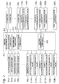
- This central management unit 301 is for centrally managing the heat source units 10a, 10b, ..., 10z installed in the dwelling units 2a, 2b, ..., 2z and, as shown in FIG. 7 , is mainly configured by a second control component 302, a fee deriving component 303, a second storage component 304 and a second communication component 305.
- the second control component 302 is electrically connected to the fourth water pump 81A, the fifth water pump 81B, the fifth electromagnetic valve 212A, the sixth electromagnetic valve 212B, the seventh electromagnetic valve 211A, the eighth electromagnetic valve 211B, the ninth electromagnetic valve 193A, the tenth electromagnetic valve 193B and the eleventh electromagnetic valves 196a, 196b, ..., 196z via a dedicated interface (not shown).
- the second control component 203 controls, in accordance with a central control program stored in the second storage unit 304, the pump performance of the fourth water pump 81A and the fifth water pump 81B, controls the opening and closing of the fifth electromagnetic valve 212A, the sixth electromagnetic valve 212B, the seventh electromagnetic valve 211 A, the eighth electromagnetic valve 211 B, the ninth electromagnetic valve 193A, the tenth electromagnetic valve 193B and the eleventh electromagnetic valves 196a, 196b, ..., 196z, generates control signals for centrally controlling the plural heat source units 10a, 10b, ..., 10z, and transmits the control signals to the first communication components 285a, 285b, ..., 285z of the individual management units through the second communication component 305.
- the fee deriving component 303 is communicably connected to the temperature sensors 98a, 98b, ..., 98z and the flowmeters 99a, 99b, ..., 99z via a dedicated interface (not shown) and derives hot water supply fees in regard to each of the dwelling units 2a, 2b, ..., 2z in accordance with a fee derivation program stored in the second storage component 304.
- methods of deriving the hot water supply fees include a method of deriving the hot water supply fees by checking temperature data and use flow rate data against a fee management table, for example.
- this fee deriving component 303 calculates the contribution percentage of each of the heat source units 10a, 10b, ..., 10z to heating the water or warm water stored in the first water supply/hot water supply tank 180A or the second water supply/hot water supply tank 180B by utilizing the energy measurement data transmitted from the first communication components 285a to determine reduced fees. Examples of methods of calculating these reduced fees include a method of multiplying the electrical power unit price by the sum of the energy measurement data and then multiplying the contribution percentage of each of the heat source unites 10a, 10b, ..., 10z.
- the second storage component 304 are stored programs such as the aforementioned central control program and fee derivation program, history data such as hot water temperature data, use flow rate data and energy measurement data, and a fee management table.
- the second communication component 305 is communicable with the first communication components 285a, 285b, ..., 285c of the plural individual management units 28a, transmits control signals and the like generated by the second control component 302 to the individual management units 28a, and receives status data and energy measurement data of the heat source units 10a, 10b, ..., 10z transmitted from the first communication components 285a, 285b, ..., 285z of the individual management units 28a.
- the first control component 281 a closes the first electromagnetic valve 17a of the flow path switching unit 19a, opens the second electromagnetic valve 18a, and, at the same time, transmits an operation start command to the compressor 11a. Further, at this time, the electrically powered expansion valve 14a is set to an appropriate opening and, at the same time, the third water pump 16a starts operation. It will be noted that, at this time, the first close valve 26a and the second close valve 27a are opened.
- gas refrigerant is sucked into and compressed by the compressor 11 a, thereafter reaches a supercritical state, is sent to the second refrigerant pipe of the first water heat exchanger 15a via the first electromagnetic valve 17a, exchanges heat with water or warm water flowing through the first water jacket of the first water heat exchanger 15a, and is cooled.
- the water or warm water flowing through the second refrigerant pipe is heated and becomes higher-temperature warm water. It will be noted that this high-temperature warm water is sent to the hot water storage tank 151a of the hot water storage tank unit 150a by the third water pump 16a.
- the supercritical refrigerant that has been cooled is sent to the electrically powered expansion valve 14a, depressurized, thereafter supplied to the air heat exchanger 13a, and exchanges heat with air blown from the fan 30a, whereby it is evaporated and becomes gas refrigerant.
- Unillustrated temperature sensors are disposed in the first water supply/hot water supply tank 180A and the second water supply/hot water supply tank 180B, and these temperature sensors are communicably connected to the central management unit 301. Additionally, when the output values of these temperature sensors fall below a lower limit value, then the second control component 302 causes the fourth water pump 81A or the fifth water pump 8 1 B to operate, at the same time requests start/stop data of the compressor 11a with respect to the individual management units 28a, identifies the heat source units 10a, 10b, ..., 10z that are not performing individual hot water storage operation at that point in time on the basis of that start/stop data, and transmits control signals to the first communication components 285a, 285b, ..., 285z of the individual management units 28a through the second communication component 305.
- the first control components 281a, 285b, ..., 285z When the first communication components 285a, 285b, ..., 285z receive the control signals from the second communication component 305, the first control components 281a, 285b, ..., 285z open the first electromagnetic valves 17a of the flow path switching units 19a, close the second electromagnetic valves 18a, and, at the same time, transmit an operation start command to the compressors 11a. Further, at this time, the electrically powered expansion valves 14a are set to an appropriate opening. It will be noted that, at this time, the first close valves 26a and the second close valves 27a are opened.
- gas refrigerant is sucked into and compressed by the compressors 11 a, thereafter reaches a supercritical state, is sent to the fifth refrigerant pipes of the second water heat exchangers 71 a, 71b, ..., 7 1 z via the second electromagnetic valves 18a, the first close valves 26a and the first communication-use refrigerant pipes 61 a, 61b, ..., 6 1 z, exchanges heat with water or warm water flowing through the second water jackets of the second water heat exchangers 71 a, 71b, ..., 71z, and is cooled.
- the water or warm water flowing through the fifth refrigerant pipes is heated and becomes high-temperature warm water.
- this high-temperature warm water (hot water) is sent to the first water supply/hot water supply tank 180A or the second water supply/hot water supply 180B by the fourth water pump 81 A or the fifth water pump 81 B.
- the supercritical refrigerant that has been cooled is sent to the electrically powered expansion valves 14a via the second communication-use refrigerant pipes 62a, 62b, ..., 62z and the second close valves 27a, depressurized, thereafter supplied to the air heat exchangers 13a, and exchanges heat with air blown from the fans 30a, whereby it is evaporated and becomes gas refrigerant.
- Water level measuring instruments are disposed in the tanks 151a, 151b, ..., 151z, 180A, and 180B pertaining to the present embodiment, and these water level measuring instruments are electrically connected to the second control component 302. Additionally, when the output values of the water level measuring instruments fall below a lower limit value, then the second control component 302 appropriately opens the electromagnetic valves 193A, 183B, 196a, 196b, 212A and 212B and supplies water or warm water (hot water) to the insides of the tanks 151a, 151b, ..., 151z, 180A and 180B. Additionally, when the output values of the water level measuring instruments reach an upper limit value, then the second control component 302 closes the electromagnetic valves 193A, 193B, 196a, 196b, 212A and 212B.
- which of the ninth electromagnetic valve 193A and the tenth electromagnetic valve 193B is opened and closed may be determined by an initial setting beforehand or can be appropriately selected in response to the demands of the residents of the dwelling units 2a, 2b, ..., 2z. In the latter case, it is necessary to dispose a selection button on the first input components 286a.
- the hot water supply system 201 pertaining to the present embodiment, the first water supply/hot water supply tank 180A and the second water supply/hot water supply tank 180B are disposed, and warm water (hot water) of different temperatures is stored. For this reason, this hot water supply system 201 can accommodate the various needs of the residents of the dwelling units 2a, 2b, ..., 2z of the multi-dwelling housing complex.
- the first water supply/hot water supply tank 180A and the second water supply/hot water supply tank 180B are interconnected by the first compensation-use communicating pipe 210A and the second compensation-use communicating pipe 210B, and exchange of warm water (hot water) can be performed by controlling the seventh electromagnetic valve 211A and the eighth electromagnetic valve 211B.
- the warm water (hot water) of the second water supply/hot water supply tank 180B or the first water supply/hot water supply tank 180A can be immediately compensated.
- the compact hot water storage tanks 151 a are disposed in the dwelling units 2a, 2b, ..., 2z. For this reason, in this hot water supply system 201, it becomes possible to store relatively low-temperature warm water in the first water supply/hot water supply tank 180A and the second water supply/hot water supply tank 180B, to further warm that warm water in the first water heat exchangers 15a after that warm water has been supplied to the hot water storage tanks 151a of the dwelling units 2a, 2b, ..., 2z, and to generate higher-temperature warm water.
- the floor heating units 50a, 50b, ..., 50z may also be connected to the first water heat exchangers 15a (multi-connection).
- the first water supply/hot water supply tank 180A and the second water supply/hot water supply tank 180B were interconnected by the first compensation-use communicating pipe 210A and the second compensation-use communicating pipe 210B, and warm water (hot water) of respectively different temperatures was stored in the first water supply/hot water supply tank 180A and the second water supply/hot water supply tank 180B, but the first water supply/hot water supply tank 180A and the second water supply/hot water supply tank 180B may also be interconnected by one compensation-use communicating pipe and warm water (hot water) of the same temperature may be stored in the first water supply/hot water supply tank 180A and the second water supply/hot water supply tank 180B.
- the hot water supply system pertaining to the present invention has the characteristic that a repair reserve fund corresponding to a heat source machine becomes unnecessary and the economical burden on residents of a condominium multi-dwelling housing complex becomes lighter, and the hot water supply system is useful as a hot water supply system for a multi-dwelling housing complex.
Landscapes
- Engineering & Computer Science (AREA)
- Physics & Mathematics (AREA)
- Mechanical Engineering (AREA)
- Thermal Sciences (AREA)
- General Engineering & Computer Science (AREA)
- Combustion & Propulsion (AREA)
- Chemical & Material Sciences (AREA)
- Fluid Mechanics (AREA)
- Computer Hardware Design (AREA)
- Water Supply & Treatment (AREA)
- Heat-Pump Type And Storage Water Heaters (AREA)
- Steam Or Hot-Water Central Heating Systems (AREA)
- Domestic Hot-Water Supply Systems And Details Of Heating Systems (AREA)
Abstract
Description
- The present invention relates to a hot water supply system that utilizes heat pump type hot water supply machines.
- In the past, a hot
water supply system 901 for a multi-dwelling housing complex such as shown inFIG. 8 has been proposed. - This hot
water supply system 901 is, as shown inFIG. 8 , mainly configured by a central hotwater supply machine 906, individual hotwater supply machines 920 andwater supply pipes - The central hot
water supply machine 906 is, as shown inFIG. 8 , mainly configured by a central hot watersupply heat pump 907, a central hotwater storage tank 908, a three-way valve 910 and atemperature sensor 912. Here, the central hot watersupply heat pump 907 is for heating tap water supplied through the upstream-mostwater supply pipe 902 to generate warm water. The central hotwater storage tank 908 is for storing the warm water generated by the central hot watersupply heat pump 907. The three-way valve 910 interconnects the central hotwater storage tank 908, abranched pipe 905 that is branched at afirst bifurcation point 904 from the upstream-mostwater supply pipe 902, and the constant temperaturewater supply pipe 911. Thetemperature sensor 912 is for measuring the temperature of the tap water or the warm water and is disposed downstream of the three-way valve 910. - The individual hot
water supply machines 920 are hot water supply machines disposed indwelling units 950 in amulti-dwelling housing complex 960 and, as shown inFIG. 8 , are mainly configured by individual hot watersupply heat pumps 921 and individual hotwater storage tanks 922, respectively. Here, the individual hot watersupply heat pumps 921 are for further heating the warm water supplied through the individualwater supply pipes 914 extending to thedwelling units 950 fromsecond bifurcation points 913 of the constant temperaturewater supply pipe 911 to generate higher-temperature warm water (hot water). The individual hotwater storage tanks 922 are for storing the high-temperature warm water (hot water) generated by the individual hot watersupply heat pumps 921. - Additionally, hot
water supply taps 924 are disposed downstream of the individual hotwater storage tanks 922, and hotwater supply openings 926 are disposed downstream thereof. Further, the individualwater supply pipes 914 are branched atthird bifurcation points 916 upstream of the individual hot watersupply heat pumps 921,water supply taps 930 are disposed downstream thereof, andwater supply openings 932 are disposed downstream thereof. Further,fourth bifurcation points 918 upstream of thewater supply openings 930 andfifth bifurcation points 919 downstream of the hotwater supply taps 924 are bypass-connected bybypass pipes 931 disposed withmixing taps 928. - In this hot water supply system 1, the central hot water
supply heat pump 907 heats the tap water supplied from the upstream-mostwater supply pipe 902 to generate warm water of 5 to 65°C. This warm water is stored in the central hotwater storage tank 908 and appropriately delivered on demand. The delivered warm water merges in the three-way valve 910 with tap water supplied from thebranched pipe 905. Then, the water temperature after merging is sensed by thetemperature sensor 912, and the mixing ratio is adjusted by the three-way valve 910 such that the temperature becomes 20°C. Thereafter, this warm water passes through the constant temperaturewater supply pipe 911 and the individualwater supply pipes 914 and is diverted at thethird bifurcation points 916, with some of the warm water being supplied to the individual hot watersupply heat pumps 921 and the remaining warm water being supplied to thewater supply taps 930. The individual hot watersupply heat pumps 921 heat the warm water supplied through the individualwater supply pipes 914 to generate warm water (hot water) of 20 to 90°C. This warm water (hot water) is stored in the individual hotwater storage tanks 922 and appropriately delivered by opening the hotwater supply taps 924. The delivered warm water (hot water) is supplied from thehot water openings 926. It will be noted that before that, it is mixed as needed by themixing taps 928 that are simultaneously opened with warm water (hot water) that has been guided to thefourth bifurcation points 918, and temperature adjustment is performed. - Additionally, when this hot
water supply system 901 is installed in a multi-dwelling housing complex, residents of thedwelling units 950 can effectively utilize free space such as verandas. - <Patent Document 1>
JP-A No. 2004-333038 - However, when such a hot water supply system is introduced to a condominium multi-dwelling housing complex, the residents of the dwelling units must themselves bear maintenance fees of the individual hot water supply machines and the like, and it is sufficiently assumed that the residents must each month pay a repair reserve fund on top of the portion corresponding to the central hot water supply machine serving as a common utility. Consequently, there is the potential for the residents of condominium multi-dwelling housing complexes to which such a hot water supply system has been introduced to become economically strapped.
- It is an object of the present invention to provide a hot water supply system whose economical burden is as small as possible on residents of a condominium multi-dwelling housing complex.
- A hot water supply system pertaining to a first invention comprises a plurality of heat source units, first fluid pipes, second radiators, a second fluid pipe and a first liquid fluid storage container. Each of the heat source units includes a refrigerant circuit. It will be noted that the "radiators" mentioned here are condensers or gas coolers, for example. Each of the refrigerant circuits is formed by sequentially connecting a compressor, a first radiator, a pressure reducing mechanism and an evaporator. The first fluid pipes are disposed with respect to the first radiators. Additionally, a fluid that exchanges heat in the first radiators with refrigerant supplied from the compressors flows through these first fluid pipes. It will be noted that the phase "fluid" mentioned here is a phrase that includes liquid fluids, gas fluids and supercritical fluids. Further, heat exchange panels for floor heating, coil components of fan coil units, and hot water supply pipes for instantaneous water heating can be connected to these first fluid pipes. The second radiators are connected in parallel with respect to the first radiators to discharge sides of the compressors. A liquid fluid that exchanges heat in the second radiators with the refrigerant supplied from the compressors flows through the second fluid pipe. The first liquid fluid storage container is connected to the second fluid pipe. Additionally, the liquid fluid is stored in this first liquid fluid storage container.
- In this hot water supply system, the plural heat source units include the refrigerant circuits that are formed by sequentially connecting the compressors, the first radiators, the pressure reducing mechanisms and the evaporators. Further, the first fluid pipes are disposed with respect to the first radiators. Additionally, the liquid that exchanges heat in the first radiators with the refrigerant supplied from the compressors flows through these first fluid pipes. Further, the second radiators are connected in parallel with respect to the first radiators to the discharge sides of the compressors. Additionally, the liquid fluid that exchanges heat in the second radiators with the refrigerant supplied from the compressors flows through this second fluid pipe. Moreover, the first liquid fluid storage container is connected to the second fluid pipe. Additionally, the liquid fluid is stored in this first liquid fluid storage container. For this reason, in this hot water supply system, when the heat source units are disposed in dwelling units of a multi-dwelling housing complex and the second radiators and the first liquid fluid storage container are installed on a roof or in an underground machine room of the multi-dwelling housing complex (when the liquid fluid storage container is installed in an underground machine room, a separate liquid fluid pump becomes necessary), not only are warm environments of the dwelling units supplied by just the heat source units installed in the dwelling units, but a shared hot water storage container can be held. In other words, in this hot water supply system, the heat source machine of the central hot water supply machine that had conventionally been installed becomes unnecessary. Consequently, in this hot water supply system, a repair reserve fund corresponding to the portion of the heat source machine and the like becomes unnecessary, and the economical burden on the residents of a condominium multi-dwelling housing complex becomes lighter.
- A hot water supply system pertaining to a second invention is the hot water supply system pertaining to the first invention and further comprises a central control device. The central control device centrally controls the plurality of heat source units.
- In this hot water supply system, the central control device is disposed. For this reason, in this hot water supply system, it becomes possible to efficiently operate the plurality of heat source units as the situation demands and to store hot water in the first liquid fluid storage container.
- A hot water supply system pertaining to a third invention is the hot water supply system pertaining to the first invention or the second invention and further comprises flow rate control mechanisms. The flow rate control mechanisms control the flow rate of the refrigerant supplied from the compressors to the first radiators and the flow rate of the refrigerant supplied from the compressors to the second radiators. It will be noted that the "flow rate control mechanisms" mentioned here are valve mechanisms configured by electromagnetic valves whose openings are capable of being adjusted, for example. Further, the phrase "flow rate control" mentioned here is a phrase that includes an aspect where the refrigerant discharged from the compressors is supplied to just the first radiators or to just the second radiators.
- In this hot water supply system, the flow rate control mechanisms are disposed. For this reason, in this hot water supply system, it becomes possible to distribute the refrigerant discharged from the compressors freely to the first radiators and the second radiators. Consequently, in this hot water supply system, it becomes possible to freely adjust the heat quantity of the refrigerant in the first radiators and the heat quantity of the refrigerant in the second radiators.
- A hot water supply system pertaining to a fourth invention is the hot water supply system of any of the first invention to the third invention and further comprises heat exchangers. The heat exchangers are connected to the first fluid pipes. It will be noted that the "heat exchangers" mentioned here can be utilized for floor heating, air conditioning, or instantaneous water heating, for example.
- In this hot water supply system, the heat exchangers are connected to the first fluid pipes. For this reason, in this hot water supply system, it becomes possible for the heat source units to provide not only the function of storing hot water in the shared first liquid fluid storage container in a multi-dwelling housing complex but also functions such as floor heating, air conditioning, and instantaneous water heating to each of the dwelling units.
- A hot water supply system pertaining to a fifth invention is the hot water supply system of any of the first invention to the fourth invention, wherein the first liquid fluid storage container is one. It will be noted that the "first liquid fluid storage container" mentioned here may be a water supply tank installed in a multi-dwelling housing complex such as an apartment complex. In this case, ordinarily, inside the first liquid fluid storage container, temperature irregularities are present in the liquid fluid, with low-temperature liquid fluid being present in the lower portion of the first liquid fluid storage container and high-temperature liquid fluid being present in the upper portion of the first liquid fluid storage container. Consequently, by ensuring that the low-temperature liquid fluid is delivered from the lower portion and that the high-temperature liquid fluid is delivered from the upper portion, the first liquid fluid storage container can function as a hot water supply-cum-water supply source.
- In this hot water supply system, the first liquid fluid storage container is one. For this reason, in this hot water supply system, it becomes possible to reduce costs corresponding to the container for storing the liquid fluid.
- A hot water supply system pertaining to a sixth invention is the hot water supply system pertaining to the fifth invention, wherein one of the second fluid pipe is disposed with respect to a plurality of the second radiators.
- In this hot water supply system, one of the second fluid pipe is disposed with respect to a plurality of the second radiators. For this reason, in this hot water supply system, it becomes possible to make the leading-out of the second fluid pipe simple.
- A hot water supply system pertaining to a seventh invention is the hot water supply system pertaining to the fifth invention or the sixth invention and further comprises a plurality of liquid fluid delivery pipes. The liquid fluid delivery pipes extend from the first liquid fluid storage container.
- In this hot water supply system, the plurality of liquid fluid delivery pipes are disposed. For this reason, in this hot water supply system, it becomes possible to distribute the high-temperature liquid fluid stored in the first liquid fluid storage container to each dwelling unit of a multi-dwelling housing complex.
- A hot water supply system pertaining to an eighth invention is the hot water supply system pertaining to any of the first invention to the fourth invention, wherein a plurality of the first liquid fluid storage containers are disposed, and the first liquid fluid storage containers are interconnected by communicating pipes such that the first liquid fluid storage containers are capable of exchanging the liquid fluid.
- In this hot water supply system, a plurality of the first liquid fluid storage containers are disposed. For this reason, in this hot water supply system, it becomes possible to store liquid fluid of different temperatures in each of the first liquid fluid storage containers, for example. Further, in this hot water supply system, even when the liquid fluid in one of the first liquid fluid storage containers is centrally used, the liquid fluid in another of the first liquid fluid storage containers can be immediately compensated.
- A hot water supply system pertaining to a ninth invention is the hot water supply system pertaining to the eighth invention and further comprises a plurality of liquid fluid delivery pipes. The liquid fluid delivery pipes extend from the first liquid fluid storage containers.
- In this hot water supply system, the plurality of liquid fluid delivery pipes are disposed with respect to the first liquid fluid storage containers. For this reason, in this hot water supply system, it becomes possible to immediately distribute the liquid fluid of various temperatures stored in the plurality of first liquid fluid storage containers to each dwelling unit of a multi-dwelling housing complex.
- A hot water supply system pertaining to a tenth invention is the hot water supply system pertaining to the seventh invention or the ninth invention and further comprises second liquid fluid storage containers. The second liquid fluid storage containers are disposed in the vicinities of the heat source units. Additionally, the liquid fluid delivered from the first liquid fluid storage containers via the liquid fluid delivery pipes is stored in these second liquid fluid storage containers.
- In this hot water supply system, the second liquid fluid storage containers are disposed. For this reason, in this hot water supply system, for example, it becomes possible to store a relatively low-temperature liquid fluid in the first liquid fluid storage containers, further heat that liquid fluid in the first radiators after that liquid fluid has been supplied to the second liquid fluid storage containers, and generate a high-temperature liquid fluid. Consequently, in this hot water supply system, it becomes possible to hold liquid fluid of a desired temperature in each dwelling unit.
- A hot water supply system pertaining to an eleventh invention is the hot water supply system of any of the seventh invention, the ninth invention and the tenth invention and further comprises flow rate measuring means and temperature measuring means. The flow rate measuring means measure the flow rate of the liquid fluid flowing in the liquid fluid delivery pipes. The temperature measuring means measure the temperature of the liquid fluid flowing in the liquid fluid delivery pipes.
- In this hot water supply system, the flow rate measuring means measure the flow rate of the liquid fluid flowing in the liquid fluid delivery pipes. Further, the temperature measuring means measure the temperature of the liquid fluid flowing in the liquid fluid delivery pipes. For this reason, in this hot water supply system, reasonable fee management can be performed in a multi-dwelling housing complex.
- A hot water supply system pertaining to a twelfth invention is the hot water supply system pertaining to any of the first invention to the eleventh invention and further comprises energy measuring means. The energy measuring means measure the amount of consumed energy of the heat source units for supplying the refrigerant to the second radiators.
- In this hot water supply system, the energy measuring means measure the amount of consumed energy of the compressor for supplying the refrigerant to the second radiators. For this reason, in this hot water supply system, the contribution percentage of each of the heat source units with respect to heating the liquid fluid stored in the first liquid fluid storage container can be determined. As a result, it becomes possible to perform distribution of electrical bills corresponding to the contribution percentage of each of the heat source units in a multi-dwelling housing complex.
- In the hot water supply system pertaining to the first invention, when the heat source units are disposed in dwelling units of a multi-dwelling housing complex and the second radiators and the first liquid fluid storage container are installed on a roof or in an underground machine room of the multi-dwelling housing complex, not only are warm environments of the dwelling units supplied by just the heat source units installed in the dwelling units, but a shared hot water storage container can be held. In other words, in this hot water supply system, the heat source machine of the central hot water supply machine that had conventionally been installed becomes unnecessary. Consequently, in this hot water supply system, a repair reserve fund corresponding to the portion of the heat source machine and the like becomes unnecessary, and the economical burden on the residents of a condominium multi-dwelling housing complex becomes lighter.
- In the hot water supply system pertaining to the second invention, it becomes possible to efficiently operate the plurality of heat source units as the situation demands and to store hot water in the first liquid fluid storage container.
- In the hot water supply system pertaining to the third invention, it becomes possible to freely adjust the heat quantity of the refrigerant in the first radiators and the heat quantity of the refrigerant in the second radiators.
- In the hot water supply system pertaining to the fourth invention, it becomes possible for the heat source units to provide not only the function of storing hot water in the shared first liquid fluid storage container in a multi-dwelling housing complex but also functions such as floor heating, air conditioning, and instantaneous water heating to each of the dwelling units.
- In the hot water supply system pertaining to the fifth invention, it becomes possible to reduce costs corresponding to the container for storing the liquid fluid.
- In the hot water supply system pertaining to the sixth invention, it becomes possible to make the leading-out of the second fluid pipe simple.
- In the hot water supply system pertaining to the seventh invention, it becomes possible to distribute the high-temperature liquid fluid stored in the first liquid fluid storage container to each dwelling unit of a multi-dwelling housing complex.
- In the hot water supply system pertaining to the eighth invention, it becomes possible to store liquid fluid of different temperatures in each of the first liquid fluid storage containers, for example. Further, in this hot water supply system, even when the liquid fluid in one of the first liquid fluid storage containers is centrally used, the liquid fluid in another of the first liquid fluid storage containers can be immediately compensated.
- In the hot water supply system pertaining to the ninth invention, it becomes possible to immediately distribute the liquid fluid of various temperatures stored in the plurality of first liquid fluid storage containers to each dwelling unit of a multi-dwelling housing complex.
- In the hot water supply system pertaining to the tenth invention, it becomes possible to store a relatively low-temperature liquid fluid in the first liquid fluid storage containers, further heat that liquid fluid in the first radiators after that liquid fluid has been supplied to the second liquid fluid storage containers, and generate a high-temperature liquid fluid. Consequently, in this hot water supply system, it becomes possible to hold liquid fluid of a desired temperature in each dwelling unit.
- In the hot water supply system pertaining to the eleventh invention, reasonable fee management can be performed in a multi-dwelling housing complex.
- In the hot water supply system pertaining to the twelfth invention, the contribution percentage of each of the heat source units with respect to heating the liquid fluid stored in the first liquid fluid storage container can be determined. As a result, it becomes possible to perform distribution of electrical bills corresponding to the contribution percentage of each of the heat source units in a multi-dwelling housing complex.
-
-
FIG. 1 is a configural diagram of a hot water supply system pertaining to a first embodiment of the present invention. -
FIG. 2 is a configural diagram of a heat source unit and a floor heating unit employed in the hot water supply system pertaining to the first embodiment of the present invention. -
FIG. 3 is a functional block diagram of an individual management unit employed in the hot water supply system pertaining to the first embodiment of the present invention. -
FIG. 4 is a functional block diagram of a central management unit employed in the hot water supply system pertaining to the first embodiment of the present invention. -
FIG. 5 is a configural diagram of a hot water supply system pertaining to a second embodiment of the present invention. -
FIG. 6 is a configural diagram of a heat source unit and an auxiliary tank unit employed in the hot water supply system pertaining to the second embodiment of the present invention. -
FIG. 7 is a functional block diagram of a central management unit employed in the hot water supply system pertaining to the second embodiment of the present invention. -
FIG. 8 is a configural diagram of a conventional hot water supply system. -
- 1
- Hot Water Supply System
- 10a, 10b, ..., 10z
- Heat Source Units
- 11a
- Compressor
- 13a
- Air Heat Exchanger (Evaporator)
- 14a
- Electrically Powered Expansion Valve (Pressure Reducing Mechanism)
- 15a
- First Water Heat Exchanger (First Radiator)
- 19a
- Flow Path Switching Unit (Flow Rate Control Mechanism)
- 20a
- Refrigerant Circuit
- 24a
- First Water Pipe (First Fluid Pipe)
- 51 a
- Heat Exchange Panel (Heat Exchanger)
- 71a, 71, ..., 71z
- Second Water Heat Exchangers (Second Radiators)
- 72
- Fifth Water Pipe (Second Fluid Pipe)
- 80
- Water Supply/Hot Water Supply Tank (First Liquid Fluid Storage Container)
- 94a, 94b, ..., 94z, 194a, 194b, ..., 194z
- Hot Water Supply Branched Pipes (Liquid Fluid Delivery Pipes)
- 98a, 98b, ..., 98z
- Temperature Sensors (Temperature Measuring Means)
- 99a, 99b, ..., 99z
- Flowmeters (Flow Rate Measuring Means)
- 102, 302
- Second Control Components (Central Control Devices)
- 151 a
- Hot Water Storage Tank (Second Liquid Fluid Storage Container)
- 180A
- First Water Supply/Hot Water Supply Tank (First Liquid Fluid Storage Container)
- 180B
- Second Water Supply/Hot Water Supply Tank (First Liquid Fluid Storage Container)
- 210A
- First Compensation-use Communicating Pipe (Communicating Pipe)
- 210B
- Second Compensation-use Communicating Pipe (Communicating Pipe)
- 282a, 282b, ..., 282z
- Energy Measuring Components (Energy Measuring Means)
- Here, a hot water supply system 1 pertaining to a first embodiment of the present invention will be described using the drawings of
FIG. 1 to FIG. 4 . - The hot water supply system 1 is a hot water supply system for a multi-dwelling housing complex and, as shown in
FIG. 1 , is mainly configured byheat source units 10a, 10b, ..., 10z,floor heating units water heating unit 70, a water supply/hotwater supply tank 80, afirst water pump 81, a first water supply main 90, a second water supply main 91, water supply branchedpipes pipes second water pump 93,individual management units 28a (seeFIG. 3 ) and a central management unit 101 (seeFIG. 4 ). - Below, the configural elements of the hot water supply system 1 will be described in detail individually.
- The
heat source units 10a, 10b, ..., 10z are so-called heat pump type heat source units and are installed on verandas or balconies ofdwelling units 2a, 2b, ..., 2z of a multi-dwelling housing complex. Here, the plural heat source units are represented by thereference numerals 10a, 10b, ..., 10z. It will be noted that because they all have the same configuration and specification, the heat source units will be described below using the heat source unit of reference numeral 10a as a representative. - The
heat source unit 10a is, as shown inFIG. 2 , mainly disposed with arefrigerant circuit 20a that is formed as a result of acompressor 11a, a flowpath switching unit 19a, a firstwater heat exchanger 15a, an electricallypowered expansion valve 14a, anair heat exchanger 13a and anaccumulator 12a being sequentially connected by a firstrefrigerant pipe 21a. Thecompressor 11a is a positive displacement inverter type compressor and becomes a drive source that compresses gaseous CO2 (carbon dioxide) refrigerant filling the inside of therefrigerant circuit 20a and causes the refrigerant to circulate inside therefrigerant circuit 20a. It will be noted that, in therefrigerant circuit 20a pertaining to the present embodiment, the CO2 refrigerant is controlled to reach a supercritical pressure on a high pressure side. The flowpath switching unit 19a is, as shown inFIG. 2 , disposed on a discharge side of thecompressor 11a and mainly includes one inlet and two outlets. A refrigerant passage extending from the inlet is branched midway and connected to inlet sides of a firstelectromagnetic valve 17a and a secondelectromagnetic valve 18a. Additionally, in the present embodiment, an outlet side of the firstelectromagnetic valve 17a is connected to the firstwater heat exchanger 15a via the refrigerant passage and the firstrefrigerant pipe 21a, and an outlet side of the secondelectromagnetic valve 18a is connected to a firstclose valve 26a via the refrigerant passage and a first branchedrefrigerant pipe 22a. It will be noted that, in this flowpath switching unit 19a, the secondelectromagnetic valve 18a is closed when the firstelectromagnetic valve 17a is open, and the firstelectromagnetic valve 17a is closed when the secondelectromagnetic valve 18a is open. The firstwater heat exchanger 15a is mainly disposed with a first water jacket and a second refrigerant pipe that is disposed inside the first water jacket and folded back several times. Additionally, in this firstwater heat exchanger 15a, water or warm water flowing into the first water jacket from a first water pipe 24a exchanges heat with high-temperature supercritical refrigerant flowing into the second refrigerant pipe from the firstrefrigerant pipe 21 a and becomes high-temperature warm water (hot water), and, at the same time, the supercritical refrigerant flowing through the second refrigerant pipe is cooled. It will be noted that the high-temperature warm water (hot water) leaving the first water jacket thereafter flows into asecond water pipe 25a. In the electricallypowered expansion valve 14a, the supercritical refrigerant that has been cooled in the firstwater heat exchanger 15a is depressurized. In theair heat exchanger 13a, the supercritical refrigerant that has been depressurized by the electricallypowered expansion valve 14a exchanges heat with air blown by afan 30a and becomes gas refrigerant, and, at the same time, that air is cooled. It will be noted that thefan 30a is, as shown inFIG. 2 , mainly configured by animpeller 31a and afan motor 32a, and thefan 30a exhibits a blowing function as a result of theimpeller 31a being driven to rotate by thefan motor 32a. Theaccumulator 12a is a compressor protector for ensuring that liquid refrigerant does not enter thecompressor 11 a, and theaccumulator 12a is disposed between an outlet side of theair heat exchanger 13a and a suction side of thecompressor 11a. Additionally, the gas refrigerant passing through theaccumulator 12a is sucked into thecompressor 11 a. - Further, in this
refrigerant circuit 20a, a second branchedrefrigerant pipe 23a is branched and extends from the firstrefrigerant pipe 21 a that interconnects an outlet side of the firstwater heat exchanger 15a and the electricallypowered expansion valve 14a, and the second branchedrefrigerant pipe 23a is connected to a secondclose valve 27a. - Further, as shown in
FIG. 2 , athird water pump 16a is disposed in thisheat source unit 10a. Further, thethird water pump 16a becomes a drive source that delivers water or warm water flowing through the first water pipe 24a to the firstwater heat exchanger 15a and a heat exchange panel 51a (described later) of thefloor heating unit 50a. - The
floor heating units dwelling units 2a, 2b, ..., 2z of the multi-dwelling housing complex. Here, the plural floor heating units are represented by thereference numerals - The
floor heating unit 50a is, as shown inFIG. 2 , mainly disposed with athird water pipe 52a, afourth water pipe 53a, and a heat exchange panel 51a. Thethird water pipe 52a is, as shown inFIG. 2 , connected to thesecond water pipe 25a of theheat source unit 10a via a first communication-use water pipe 41a. Thefourth water pipe 53a is, as shown inFIG. 2 , connected to the first water pipe 24a of theheat source unit 10a via a second communication-use water pipe 42a. The heat exchange panel 51a is, as shown inFIG. 2 , connected to thethird water pipe 52a and thefourth water pipe 53a and warms the floor of the room by warm water flowing inside the heat exchange panel 51 a. It will be noted that the water or warm water delivered from the heat exchange panel 51a flows through thefourth water pipe 53a and the second communication-use water pipe 42a, again flows into the first water pipe 24a of theheat source unit 10a, and is warmed by the firstwater heat exchanger 15a. It will be noted that the flow of this water or warm water is generated by thethird water pump 16a of theheat source unit 10a (refer to the arrows inFIG. 2 ). - The
water heating unit 70 is a unit for heating the water or warm water stored in the water supply/hotwater supply tank 80 to generate high-temperature warm water (hot water) and is installed on a roof of the multi-dwelling housing complex. Thiswater heating unit 70 is disposed with thirdrefrigerant pipes 73a, 73b, ..., 73z, fourthrefrigerant pipes 74a, 74b, ..., 74z, secondwater heat exchangers fifth water pipe 72. The thirdrefrigerant pipes 73a, 73b, ..., 73z are connected to the firstclose valves 26a, 26b, ..., 26z of theheat source units 10a, 10b, ..., 10z via first communication-use refrigerant pipes 61 a, 61b,..., 61z, and are connected to the secondwater heat exchangers refrigerant pipes 74a, 74b, ..., 74z are connected to the secondclose valves 27a, 27b, ..., 27z of theheat source units 10a, 10b, ..., 10z via second communication-use refrigerant pipes 62a, 62b, ..., 62z, and are connected to the secondwater heat exchangers water heat exchangers water heat exchangers first water pump 81 from the water supply/hotwater supply tank 80, passes through thefifth water pipe 72 and flows into the second water jackets exchanges heat with high-temperature supercritical refrigerant flowing into the fifth refrigerant pipes and becomes high-temperature warm water, and, at the same time, the supercritical refrigerant flowing through the fifth refrigerant pipes is cooled. It will be noted that the high-temperature warm water leaving the second water jackets is thereafter returned to the water supply/hotwater supply tank 80 through a seventh water pipe 83 (refer to the arrows inFIG. 2 ). - The water supply/hot
water supply tank 80 is a tank that simultaneously stores water and high-temperature warm water (hot water) and is installed on the roof of the multi-dwelling housing complex. Here, that "the water supply/hotwater supply tank 80 simultaneously stores water and high-temperature warm water (hot water)" is attributed to the fact that temperature irregularities arise in liquid fluid inside a first liquid fluid storage container, with low-temperature liquid fluid being present in the lower portion of the first liquid fluid storage container and high-temperature liquid fluid being present in the upper portion of the first liquid fluid storage container. - The
first water pump 81 is connected to the water supply/hotwater supply tank 80 via aneighth water pipe 82 and plays the role of delivering the water and warm water (hot water) stored in the water supply/hotwater supply tank 80 to thefifth water pipe 72 of thewater heating unit 70. - The first water supply main 90 is a water supply pipe that extends from a waterworks pipe (not shown) buried underground to the water supply/hot
water supply tank 80 installed on the roof of the multi-dwelling housing complex. It will be noted that the water supplied from the waterworks pipe is supplied to the water supply/hotwater supply tank 80 by a pump (not shown) disposed midway in the first water supply main 90. - The second water supply main 91 is a water supply pipe that becomes the backbone for supplying water to each of the
dwelling units 2a, 2b, ..., 2z of the multi-dwelling housing complex, is connected to the lower portion of the water supply/hotwater supply tank 80, and runs through the inside of the building frame of the multi-dwelling housing complex. - The water supply branched
pipes dwelling units 2a, 2b, ..., 2z of the multi-dwelling housing complex. Further, firstmanual valves pipes manual valves dwelling units 2a, 2b, ..., 2z. Further, unillustrated water meters are connected to these water supply branchedpipes - The hot water supply main 92 is a hot water supply pipe that becomes the backbone for supplying hot water to each of the
dwelling units 2a, 2b, ..., 2z of the multi-dwelling housing complex, runs through the inside of the building frame of the multi-dwelling housing complex from the upper portion of the water supply/hotwater supply tank 80, and again returns to the water supply/hotwater supply tank 80. - The hot water supply branched
pipes dwelling units 2a, 2b, ..., 2z of the multi-dwelling housing complex. Further, secondmanual valves pipes manual valves dwelling units 2a, 2b, ..., 2z. Further,temperature sensors flowmeters pipes temperature sensors flowmeters central management unit 101 such that how much hot water of what °C the residents of each of thedwelling units 2a, 2b, ..., 2z have used can be understood. - The
second water pump 93 is disposed in the hot water supply main 92 downstream of the bifurcation point of the hot water supply branchedpipe 94a and becomes a drive source that again returns the hot water flowing in the hot water supply main 92 to the water supply/hotwater supply tank 80. - The
individual management units 28a are installed on a wall surface or the like of a room in each of thedwelling units 2a, 2b, ..., 2z of the multi-dwelling housing complex. The individual management units installed in thedwelling units 2a, 2b, ..., 2z all have the same configuration and specification, so the individual management units will be described below using the individual management unit for the floor heating unit represented byreference numeral 50a as a representative. - The
individual management unit 28a, for example, controls theheat source unit 10a, 10b, ..., 10z in response to the demands of the residents of thedwelling unit 2a, 2b, ..., 2z or in accordance with a command from thecentral management unit 101, collect necessary data from theheat source unit 10a, 10b, ..., 10z, and transmit the data to thecentral management unit 101. As shown inFIG. 3 , theindividual management units 28a is mainly configured by afirst control component 281a, anenergy measuring component 282a, aswitch determining component 283a, afirst storage component 284a, afirst input component 286a, afirst display component 287a and afirst communication component 285a. - The
first control component 281a is electrically connected to thecompressor 11a, the electricallypowered expansion valve 14a, the flowpath switching unit 19a, thefan motor 32a and thethird water pump 16a via a dedicated interface (not shown) and controls each of thedevices first storage component 284a. - The
energy measuring component 282a is communicably connected to thecompressor 11a, the electricallypowered expansion valve 14a, the flowpath switching unit 19a and thefan motor 32a via a dedicated interface (not shown) and measures the quantity of electrical energy that each of thedevices electromagnetic valve 18a is in an open state. - The
switch determining component 283a is electrically connected to the flowpath switching unit 19a and switches between opened and closed states of the firstelectromagnetic valve 17a and the secondelectromagnetic valve 18a in response to the demands of the residents of thedwelling unit 2a, 2b, ..., 2z or in accordance with a command from thecentral management unit 101. - In the
first storage component 284a are stored programs such as the aforementioned individual control program and a communication program, and data necessary for performing control and communication. - A floor heating ON/OFF button, a temperature adjustment button, and the like are disposed in the
first input component 286a, and when those buttons are pressed by residents or the like of thedwelling unit 2a, 2b, ..., 2z, starting/stopping and positive displacement control of thecompressor 11a of theheat source unit 10a, 10b, ..., 10z, control of the opening of the electricallypowered expansion valve 14a, and status switching of the flowpath switching unit 19a are performed. - The
first display component 287a displays the start/stop status of floor heating, the set temperature, the operating area, and whether or not theheat source unit 10a, 10b, ..., 10z are being centrally controlled. - The
first communication component 285a is communicable with asecond communication component 105 of thecentral management unit 101, transmits status data and energy measurement data of theheat source unit 10a, 10b, ..., 10z to thecentral management unit 101, and receives control signals and the like transmitted from thecentral management unit 101. - The
central management unit 101 is installed in a management room, a machine room, or the like of the multi-dwelling housing complex. - This
central management unit 101 is for centrally managing theheat source units 10a, 10b, ..., 10z installed in thedwelling units 2a, 2b, ..., 2z and, as shown inFIG. 4 , is mainly configured by asecond control component 102, afee deriving component 103, asecond storage component 104 and asecond communication component 105. - The
second control component 102 is electrically connected to thefirst water pump 81 via a dedicated interface (not shown), controls thefirst water pump 81 in accordance with a central control program stored in thesecond storage component 104, generates control signals for centrally controlling the pluralheat source units 10a, 10b, ..., 10z, and transmits the control signals to thefirst communication components individual management units 28a through thesecond communication component 105. - The
fee deriving component 103 is communicably connected to thetemperature sensors flowmeters dwelling units 2a, 2b, ..., 2z in accordance with a fee derivation program stored in thesecond storage component 104. Examples of methods of deriving the hot water supply fees include a method of deriving the hot water supply fees by checking temperature data and use flow rate data against a fee management table, for example. Further, thisfee deriving component 103 calculates the contribution percentage of each of theheat source units 10a, 10b, ..., 10z to heating the water or warm water stored in the water supply/hotwater supply tank 80 by utilizing the energy measurement data transmitted from thefirst communication components - In the
second storage component 104 are stored programs such as the aforementioned central control program and fee derivation program, history data such as temperature data, use flow rate data and energy measurement data, and a fee management table. - The
second communication component 105 is communicable with thefirst communication components individual management units 28a, transmits control signals and the like generated by thesecond control component 102 to theindividual management units 28a, and receives status data and energy measurement data of the heat source units transmitted from thefirst communication components individual management units 28a. - Here, the floor heating function in the
dwelling unit 2a will be representatively described. - In the
dwelling unit 2a, when a resident switches ON the floor heating ON/OFF button with thefirst input component 286a of theindividual management unit 28a, then thefirst control component 281a closes the firstelectromagnetic valve 17a of the flowpath switching unit 19a, opens the secondelectromagnetic valve 18a, and, at the same time, transmits an operation start command to thecompressor 11 a. Further, at this time, the electricallypowered expansion valve 14a is set to an appropriate opening and, at the same time, thethird water pump 16a starts operation. It will be noted that, at this time, the firstclose valve 26a and the secondclose valve 27a are opened. - Then, when the
compressor 11 a starts operation, gas refrigerant is sucked into and compressed by thecompressor 11a, thereafter reaches a supercritical state, is sent to the second refrigerant pipe of the firstwater heat exchanger 15a via the firstelectromagnetic valve 17a, exchanges heat with water or warm water flowing through the first water jacket of the firstwater heat exchanger 15a, and is cooled. In other words, at this time, the water or warm water flowing through the second refrigerant pipe is heated and becomes high-temperature warm water (hot water). It will be noted that this high-temperature warm water (hot water) is sent to the heat exchange panel 51a of thefloor heating unit 50a by thethird water pump 16a, warms the floor and space of thedwelling unit 2a, is cooled at the same time, and is thereafter again sent to the firstwater heat exchanger 15a by thethird water pump 16a. - Then, the supercritical refrigerant that has been cooled is sent to the electrically
powered expansion valve 14a, depressurized, thereafter sent to theair heat exchanger 13a, and exchanges heat with air blown form thefan 30a, whereby it is evaporated and becomes gas refrigerant. - Then, that gas refrigerant is again sucked into the
compressor 11 a via theaccumulator 12a. In this manner, floor heating operation is performed (refer to the arrows inFIG 2 ). - An unillustrated temperature sensor is disposed in the water supply/hot
water supply tank 80, and this temperature sensor is communicably connected to thecentral management unit 101. Additionally, when the output value of this temperature sensor falls below a lower limit value, then thesecond control component 102 causes thefirst water pump 81 to operate, at the same time requests floor heating ON/OFF status data with respect to theindividual management units 28a, identifies theheat source units 10a, 10b, ..., 10z that are not performing floor heating operation at that point in time on the basis of that ON/OFF status data, and transmits control signals to thefirst communication components individual management units 28a through thesecond communication component 105. - When the
first communication components second communication component 105, thefirst control components 281a open the firstelectromagnetic valves 17a of the flowpath switching units 19a, closes the secondelectromagnetic valves 18a, and, at the same time, transmit an operation start command to thecompressors 11a. Further, at this time, the electricallypowered expansion valves 14a are set to an appropriate opening. It will be noted that, at this time, the firstclose valves 26a and the secondclose valves 27a are opened. - Then, when the
compressors 11a starts operation, gas refrigerant is sucked into and compressed by thecompressors 11a, thereafter reaches a supercritical state, is sent to the fifth refrigerant pipes of the secondwater heat exchangers electromagnetic valves 18a, the firstclose valves 26a and the first communication-use refrigerant pipes 6 1 a, 61b, ..., 61z, exchanges heat with water or warm water flowing through the second water jackets of the secondwater heat exchangers water supply tank 80 by thefirst water pump 81. Then, when the high-temperature warm water (hot water) that has been sent to the water supply/hotwater supply tank 80 has not reached a set hot water temperature, then that warm water (hot water) is further sent to the secondwater heat exchangers first water pump 81. Conversely, when the high-temperature warm water (hot water) that has been sent to the water supply/hotwater supply tank 80 has reached the set hot water temperature, then thecompressors 11 a and thefirst water pump 81 are caused to stop. - Then, the supercritical refrigerant that has been cooled is sent to the electrically
powered expansion valves 14a via the second communication-use refrigerant pipes 62a, 62b, ..., 62z and the secondclose valves 27a, depressurized, thereafter supplied to theair heat exchangers 13a, and exchanges heat with air blown from thefans 30a, whereby it is evaporated and becomes gas refrigerant. - Then, that gas refrigerant is again sucked into the
compressors 11 a via theaccumulator 12a. In this manner, operation of heating the water inside the water supply/hot water supply tank is performed (refer to the arrows inFIG. 2 ). - It will be noted that, during this operation of heating the water inside the water supply/hot water supply tank, when floor heating ON/OFF is ON during central control, floor heating is given priority.
- In the hot water supply system 1 pertaining to the present embodiment, the plural
heat source units 10a, 10b, ..., 10z are installed in thedwelling units 2a, 2b, ..., 2z, and each of thoseheat source units 10a, 10b, ..., 10z includes therefrigerant circuit 20a that is formed by sequentially connecting thecompressor 11a, the firstwater heat exchanger 15a, the electricallypowered expansion valve 14a and theair heat exchanger 13a by the firstrefrigerant pipe 21 a. Further, theseheat source units 10a, 10b, ..., 10z are connected to thefloor heating units water heat exchangers 15a. Further, the secondwater heat exchangers 71 a are disposed in thewater heating unit 70 installed on the roof, and these secondwater heat exchangers 71a are connected in parallel with the firstwater heat exchangers 15a to the discharge side of thecompressors 11 a of theheat source units 10a, 10b, ..., 10z. Additionally, the water or warm water stored in the water supply/hotwater supply tank 80 installed on the roof is heated by thewater heating unit 70. For this reason, in this hot water supply system 1, not only are warm environments of thedwelling units 2a, 2b, ..., 2z supplied by just theheat source units 10a, 10b, ..., 10z installed in thedwelling units 2a, 2b, ..., 2z, but shared hot water can be held in the water supply/hotwater supply tank 80. In other words, in this hot water supply system 1, the heat source machine of the central hot water supply machine that had conventionally been installed becomes unnecessary. Consequently, in this hot water supply system 1, a repair reserve fund corresponding to the heat source machine and the like becomes unnecessary, and the economical burden on the residents of the condominium multi-dwelling housing complex becomes lighter. - In the hot water supply system 1 pertaining to the present embodiment, the
central management unit 101 and the flow path switchunits 19a are disposed. For this reason, in this hot water supply system 1, theheat source units 10a, 10b, ..., 10z that are not being utilized can be selected and utilized to heat the water or warm water inside the water supply/hotwater supply tank 80. - In the hot water supply system 1 pertaining to the present embodiment, the water supply/hot
water supply tank 80 doubles as a water supply tank and a hot water supply tank. For this reason, in this hot water supply system 1, costs corresponding to the shared hot water supply tank can be reduced. - In the hot water supply system 1 pertaining to the present embodiment, the
flowmeters pipes temperature sensors pipes central management unit 101 derives the hot water supply fees in regard to each of thedwelling units 2a, 2b, ..., 2z. For this reason, in this hot water supply system 1, reasonable hot water supply fee management can be performed. - In the hot water supply system pertaining to the present embodiment, the
central management unit 101 calculates the contribution percentage of each of theheat source units 10a, 10b, ..., 10z to heating the water or warm water stored in the water supply/hotwater supply tank 80 by utilizing the energy measurement data supplied from theindividual management units 28a to determine reduced fees. For this reason, in this hot water supply system 1, it becomes possible to perform distribution of electrical bills corresponding to the contribution percentage of each of theheat source units 10a, 10b, ..., 10z. - In the hot water supply system 1 pertaining to the preceding embodiment, the flow
path switching units 19a were employed, but instead of these, flow rate adjusting units may also be employed. In other words, the hot water supply system may also be configured such that it can distribute the supercritical refrigerant discharged from thecompressors 11 a in an appropriate ratio to the firstwater heat exchangers 15a and the secondwater heat exchangers 71 a. By configuring the hot water supply system in this manner, in this hot water supply system 1, the floor heating function and the function of heating the water inside the water supply/hot water supply tank can be simultaneously realized. - In the hot water supply system 1 pertaining to the preceding embodiment, the third water pumps 16a were disposed in the
heat source units 10a, 10b, ..., 10z, but instead of these, thethird water pumps 16a may also be disposed in thefloor heating units 50a. - In the hot water supply system 1 pertaining to the preceding embodiment, carbon dioxide was employed as the refrigerant, but instead of this, a refrigerant such as ammonia, hydrocarbon, or fluorocarbon may also be utilized. In this case, the first
water heat exchangers 15a and the secondwater heat exchangers 71a function as condensers not as gas coolers. - In the hot water supply system 1 pertaining to the preceding embodiment, the
water heating unit 70 was installed on the roof, but thewater heating unit 70 may also be installed in an underground machine room or the like. - In the hot water supply system 1 pertaining to the preceding embodiment, the hot water supply branched
pipes dwelling units 2a, 2b, ..., 2z, but the hot water supply system may also be configured such that just one of the hot water supply branchedpipes - In the hot water supply system 1 pertaining to the preceding embodiment, the
heat source units 10a, 10b, ..., 10z were connected to thefloor heating units water heat exchangers 15a, but theheat source units 10a, 10b, ..., 10z may also be connected to coil components of fan coil units or the like via the firstwater heat exchangers 15a. By configuring the hot water supply system in this manner, heating of thedwelling units 2a, 2b, ..., 2z becomes possible. - In the hot water supply system pertaining to the preceding embodiment, the flow
path switching units 19a disposed with the firstelectromagnetic valves 17a and the secondelectromagnetic valves 18a were employed in therefrigerant circuits 20a, but instead of these, a three-way valves may also be employed. - In the hot water supply system 1 pertaining to the preceding embodiment, the positive displacement
inverter type compressor 11 a was installed in theheat source units 10a, 10b, ..., 10z, but instead of this, a non-inverter type compressor may also be installed. - Here, a hot
water supply system 201 pertaining to a second embodiment of the present invention will be described using the drawings ofFIG. 5 to FIG. 7 . It will be noted that, because there are configural elements in the hotwater supply system 201 pertaining to the second embodiment that correspond to the configural elements of the hot water supply system 1 pertaining to the first embodiment, description in regard to those corresponding portions will be omitted by adding reference numerals that are the same as the reference numerals used to describe the hot water supply system 1 pertaining to the first embodiment. - The hot
water supply system 201 is a hot water supply system for a multi-dwelling housing complex and, as shown inFIG. 5 , is mainly configured byheat source units 10a, 10b, ..., 10z, hot waterstorage tank units water heating unit 170A, a secondwater heating unit 170B, a first water supply/hotwater supply tank 180A, a second water supply/hotwater supply tank 180B, afourth water pump 81 A, afifth water pump 81B, a first water supply main 190, a second water supply main 91, water supply branchedpipes pipes water supply pipes individual management units 28a (seeFIG. 3 ) and a central management unit 301 (seeFIG. 7 ). - Below, the configural elements of the hot
water supply system 201 will be described in detail individually. - The
heat source units 10a, 10b, ..., 10z are the same as theheat source units 10a, 10b, ..., 10z that are employed in the hot water supply system 1 pertaining to the first embodiment. For that reason, description will be omitted here. - The hot water
storage tank units heat storage units 10a, 10b, ..., 10z on verandas or balconies of thedwelling units 2a, 2b, ..., 2z of the multi-dwelling housing complex. Here, the plural hot water storage tank units are represented by thereference numerals reference numeral 150a as a representative. - The hot water
storage tank unit 150a is, as shown inFIG. 6 , mainly disposed with aninth water pipe 152a, atenth water pipe 153a and a hotwater storage tank 151a. Theninth water pipe 152a is, as shown inFIG 6 , connected to thesecond water pipe 25a of theheat source unit 10a via the first communication-use water pipe 41 a. Thetenth water pipe 153a is, as shown inFIG. 6 , connected to the first water pipe 24a of theheat source unit 10a via the second communication-use water pipe 42a. The hotwater storage tank 151 a is, as shown inFIG. 6 , connected to theninth water pipe 152a and thetenth water pipe 153a and is for storing warm water (hot water) that has been warmed in the firstwater heat exchanger 15a. It will be noted that the water or warm water inside the hotwater storage tank 151a is caused to circulate by thethird water pump 16a of theheat source unit 10a until the output value of a temperature sensor disposed inside the hotwater storage tank 151a reaches a constant value. Further, the hot water supply branchedpipe 94a is connected to the upper portion of this hotwater storage tank 151a, and the terminal hotwater supply pipe 194a is connected to a place slightly higher than the intermediate portion of the hotwater storage tank 151a. - The first
water heating unit 170A and the secondwater heating unit 170B are units where thewater heating unit 70 employed in the hot water supply system 1 pertaining to the first embodiment has been divided into two. It will be noted that, in the present embodiment, the water pipe disposed in the firstwater heating unit 170A will be called an eleventh water pipe and be represented by thereference numeral 172A. Further, the water pipe disposed in the secondwater heating unit 170B will be called a twelfth water pipe and be represented byreference numeral 172B. Further, as will be apparent fromFIG 5 , in the present embodiment, the firstwater heating unit 170A corresponds to thefourth water pump 81 A and the first water supply/hotwater supply tank 180A, and the secondwater heating unit 170B corresponds to the fifth water pump 8 1 B and the second water supply/hotwater supply tank 180B. - The first water supply/hot
water supply tank 180A and the second water supply/hotwater supply tank 180B have the same function as that of the water supply/hotwater supply tank 80 employed in the hot water supply system 1 pertaining to the first embodiment but are largely different from the water supply/hotwater supply tank 80 of the first embodiment in that they are interconnected by a first compensation-use communicating pipe 210A and a second compensation-use communicating pipe 210B. Here, the first compensation-use communicating pipe 210A is disposed so as to have a falling gradient from a seventhelectromagnetic valve 211A connected to the first water supply/hotwater supply tank 180A towards the second water supply/hotwater supply tank 180B. The second compensation-use communicating pipe 210B is disposed so as to have a falling gradient from an eighthelectromagnetic valve 211 B connected to the second water supply/hotwater supply tank 180B towards the first water supply/hotwater supply tank 180A. Further, warm water (hot water) of mutually different temperatures is stored in these water supply/hotwater supply tanks - The
fourth water pump 81 A and the fifth water pump 8 1 B have the same function as that of thefirst water pump 81 employed in the hot water supply system 1 pertaining to the first embodiment. - The first water supply main 190 is a water supply pipe that is branched midway and extends from the waterworks pipe buried underground to the first water supply/hot
water supply tank 180A and the second water supply/hotwater supply tank 180B installed on the roof of the multi-dwelling housing complex. It will be noted that the water supplied from the waterworks pipe (not shown) is supplied to the first water supply/hotwater supply tank 180A and the second water supply/hotwater supply tank 180B by a pump (not shown) disposed midway in the first water supply main 190. It will be noted that a fifthelectromagnetic valve 212A and a sixthelectromagnetic valve 212B are disposed between the bifurcation point of the first water supply main 190 and each of the water supply/hot water supplymain tanks - The second water supply main 91 is the same as the second water supply main 91 pertaining to the first embodiment.
- The water supply branched
pipes pipes - The hot water supply main 192 is a hot water supply pipe that becomes the backbone for supplying hot water to each of the
dwelling units 2a, 2b, ..., 2z of the multi-dwelling housing complex, and is mainly configured by a first hot water supply main 192C, a second hot water supply main 192A and a third hot water supply main 192B. The second hot water supply main 192A extends from the upper portion of the first water supply/hotwater supply tank 180A, and a ninthelectromagnetic valve 193A is disposed midway thereof. The third hot water supply main 192B extends from the upper portion of the second water supply/hotwater supply tank 180B, and a tenthelectromagnetic valve 193B is disposed midway thereof. The first hot water supply main 192C runs through the inside of the building frame of the multi-dwelling housing complex as shown inFIG 5 so as to join together the terminal end of the second hot water supply main 192A and the terminal end of the third hot water supply main 192B. - The hot water supply branched
pipes FIG. 1 andFIG. 2 , extend to the hotwater storage tanks 151a, 151b, ..., 151z of the hot waterstorage tank units dwelling units 2a, 2b, ..., 2z of the multi-dwelling housing complex. Additionally,temperature sensors flowmeters pipes temperature sensors flowmeters central management unit 101 such that how much hot water of what °C the residents of each of thedwelling units 2a, 2b, ..., 2z have used can be understood. Further, eleventhelectromagnetic valves pipes - The terminal hot
water supply pipes dwelling units 2a, 2b, ..., 2z from the hotwater storage tanks 151a, 151b, ..., 151z. Secondmanual valves water supply pipes manual valves dwelling units 2a, 2b, ..., 2z. - The individual management units have the same structure as that of the
individual management units 28a pertaining to the first embodiment, but their functions are in part different. Here, reference will be made to the points of difference with theindividual management units 28a pertaining to the first embodiment. The specific point of difference is that the management target changes from floor heating to hot water storage. - Specifically, first, in the first embodiment, the floor heating ON/OFF button and the temperature adjustment button were disposed in the
first input component 286a, but in the present embodiment, a hot water storage ON/OFF button, a hot water temperature adjustment button, and a hot water storage volume adjustment button are disposed on the first input component. - Further, in the first embodiment, the start/stop status of floor heating, the set temperature and the operating area were displayed on the
first display component 287a, but in the present embodiment, whether or not heating operation is being performed, whether or not hot water is being supplied from the water supply/hotwater supply tanks water storage tank 151a (measured by the temperature sensor inside the hotwater storage tank 151a) and the set temperature, the remaining volume of storage hot water inside the hotwater storage tank 151 a (measured by a water level measuring instrument) and the set hot water volume are displayed on the first display component. - The
central management unit 301 is installed in a management room, a machine room, or the like of the multi-dwelling housing complex. - This
central management unit 301 is for centrally managing theheat source units 10a, 10b, ..., 10z installed in thedwelling units 2a, 2b, ..., 2z and, as shown inFIG. 7 , is mainly configured by asecond control component 302, afee deriving component 303, asecond storage component 304 and asecond communication component 305. - The
second control component 302 is electrically connected to thefourth water pump 81A, thefifth water pump 81B, the fifthelectromagnetic valve 212A, the sixthelectromagnetic valve 212B, the seventhelectromagnetic valve 211A, the eighthelectromagnetic valve 211B, the ninthelectromagnetic valve 193A, the tenthelectromagnetic valve 193B and the eleventhelectromagnetic valves second storage unit 304, the pump performance of thefourth water pump 81A and thefifth water pump 81B, controls the opening and closing of the fifthelectromagnetic valve 212A, the sixthelectromagnetic valve 212B, the seventhelectromagnetic valve 211 A, the eighthelectromagnetic valve 211 B, the ninthelectromagnetic valve 193A, the tenthelectromagnetic valve 193B and the eleventhelectromagnetic valves heat source units 10a, 10b, ..., 10z, and transmits the control signals to thefirst communication components second communication component 305. - The
fee deriving component 303 is communicably connected to thetemperature sensors flowmeters dwelling units 2a, 2b, ..., 2z in accordance with a fee derivation program stored in thesecond storage component 304. Examples of methods of deriving the hot water supply fees include a method of deriving the hot water supply fees by checking temperature data and use flow rate data against a fee management table, for example. Further, thisfee deriving component 303 calculates the contribution percentage of each of theheat source units 10a, 10b, ..., 10z to heating the water or warm water stored in the first water supply/hotwater supply tank 180A or the second water supply/hotwater supply tank 180B by utilizing the energy measurement data transmitted from thefirst communication components 285a to determine reduced fees. Examples of methods of calculating these reduced fees include a method of multiplying the electrical power unit price by the sum of the energy measurement data and then multiplying the contribution percentage of each of the heat source unites 10a, 10b, ..., 10z. - In the
second storage component 304 are stored programs such as the aforementioned central control program and fee derivation program, history data such as hot water temperature data, use flow rate data and energy measurement data, and a fee management table. - The
second communication component 305 is communicable with thefirst communication components individual management units 28a, transmits control signals and the like generated by thesecond control component 302 to theindividual management units 28a, and receives status data and energy measurement data of theheat source units 10a, 10b, ..., 10z transmitted from thefirst communication components individual management units 28a. - Here, the individual hot water storage function in the
dwelling unit 2a will be representatively described. - In
dwelling unit 2a, when the hot water storage ON/OFF button is switched ON with thefirst input component 286a of theindividual management unit 28a and the output value from the temperature sensor disposed inside the hotwater storage tank 151 a is lower than a lower limit value, then thefirst control component 281 a closes the firstelectromagnetic valve 17a of the flowpath switching unit 19a, opens the secondelectromagnetic valve 18a, and, at the same time, transmits an operation start command to thecompressor 11a. Further, at this time, the electricallypowered expansion valve 14a is set to an appropriate opening and, at the same time, thethird water pump 16a starts operation. It will be noted that, at this time, the firstclose valve 26a and the secondclose valve 27a are opened. - Then, when the
compressor 11 a starts operation, gas refrigerant is sucked into and compressed by thecompressor 11 a, thereafter reaches a supercritical state, is sent to the second refrigerant pipe of the firstwater heat exchanger 15a via the firstelectromagnetic valve 17a, exchanges heat with water or warm water flowing through the first water jacket of the firstwater heat exchanger 15a, and is cooled. In other words, at this time, the water or warm water flowing through the second refrigerant pipe is heated and becomes higher-temperature warm water. It will be noted that this high-temperature warm water is sent to the hotwater storage tank 151a of the hot waterstorage tank unit 150a by thethird water pump 16a. Then, when the high-temperature warm water sent to the hotwater storage tank 151a has not reached a set hot water temperature, then that warm water is further sent to the firstwater heat exchanger 15a by thethird water pump 16a. Conversely, when the high-temperature warm water that has been sent to the hotwater storage tank 151a has reached the set hot water temperature, then thecompressor 11a and thethird water pump 16a are caused to stop. - Then, the supercritical refrigerant that has been cooled is sent to the electrically
powered expansion valve 14a, depressurized, thereafter supplied to theair heat exchanger 13a, and exchanges heat with air blown from thefan 30a, whereby it is evaporated and becomes gas refrigerant. - Then, that gas refrigerant is again sucked into the
compressor 11 a via theaccumulator 12a. In this manner, individual hot water storage operation is performed (refer to the arrows inFIG. 6 ). - Unillustrated temperature sensors are disposed in the first water supply/hot
water supply tank 180A and the second water supply/hotwater supply tank 180B, and these temperature sensors are communicably connected to thecentral management unit 301. Additionally, when the output values of these temperature sensors fall below a lower limit value, then thesecond control component 302 causes thefourth water pump 81A or the fifth water pump 8 1 B to operate, at the same time requests start/stop data of thecompressor 11a with respect to theindividual management units 28a, identifies theheat source units 10a, 10b, ..., 10z that are not performing individual hot water storage operation at that point in time on the basis of that start/stop data, and transmits control signals to thefirst communication components individual management units 28a through thesecond communication component 305. - When the
first communication components second communication component 305, thefirst control components electromagnetic valves 17a of the flowpath switching units 19a, close the secondelectromagnetic valves 18a, and, at the same time, transmit an operation start command to thecompressors 11a. Further, at this time, the electricallypowered expansion valves 14a are set to an appropriate opening. It will be noted that, at this time, the firstclose valves 26a and the secondclose valves 27a are opened. - Then, when the
compressors 11 a start operation, gas refrigerant is sucked into and compressed by thecompressors 11 a, thereafter reaches a supercritical state, is sent to the fifth refrigerant pipes of the secondwater heat exchangers electromagnetic valves 18a, the firstclose valves 26a and the first communication-use refrigerant pipes 61 a, 61b, ..., 6 1 z, exchanges heat with water or warm water flowing through the second water jackets of the secondwater heat exchangers water supply tank 180A or the second water supply/hot water supply 180B by thefourth water pump 81 A or thefifth water pump 81 B. Then, when the high-temperature warm water (hot water) that has been sent to the first water supply/hotwater supply tank 180A or the second water supply/hotwater supply tank 180B has not reached a set hot water temperature, then that warm water (hot water) is further sent to the secondwater heat exchangers fourth water pump 81A or thefifth water pump 81B. Conversely, when the high-temperature warm water (hot water) that has been sent to the first water supply/hotwater supply tank 180A or the second water supply/hotwater supply tank 180B has reached the set hot water temperature, then thecompressors 11a and thefourth water pump 81A or thefifth water pump 81 B are caused to stop. - Then, the supercritical refrigerant that has been cooled is sent to the electrically
powered expansion valves 14a via the second communication-use refrigerant pipes 62a, 62b, ..., 62z and the secondclose valves 27a, depressurized, thereafter supplied to theair heat exchangers 13a, and exchanges heat with air blown from thefans 30a, whereby it is evaporated and becomes gas refrigerant. - Then, that gas refrigerant is again sucked into the
compressors 11 a via theaccumulators 12a. In this manner, operation of heating the water inside the water supply/hot water supply tanks is performed (refer to the arrows inFIG. 6 ). - It will be noted that, during this operation of heating the water inside the water supply/hot water supply tanks, when the output values of the temperature sensors disposed inside the hot
water storage tanks 151a reach the lower limit value during central control, then individual hot water storage operation is given priority. - Water level measuring instruments are disposed in the
tanks 151a, 151b, ..., 151z, 180A, and 180B pertaining to the present embodiment, and these water level measuring instruments are electrically connected to thesecond control component 302. Additionally, when the output values of the water level measuring instruments fall below a lower limit value, then thesecond control component 302 appropriately opens theelectromagnetic valves tanks 151a, 151b, ..., 151z, 180A and 180B. Additionally, when the output values of the water level measuring instruments reach an upper limit value, then thesecond control component 302 closes theelectromagnetic valves - It will be noted that which of the ninth
electromagnetic valve 193A and the tenthelectromagnetic valve 193B is opened and closed may be determined by an initial setting beforehand or can be appropriately selected in response to the demands of the residents of thedwelling units 2a, 2b, ..., 2z. In the latter case, it is necessary to dispose a selection button on thefirst input components 286a. - In the hot
water supply system 201 pertaining to the present embodiment, the first water supply/hotwater supply tank 180A and the second water supply/hotwater supply tank 180B are disposed, and warm water (hot water) of different temperatures is stored. For this reason, this hotwater supply system 201 can accommodate the various needs of the residents of thedwelling units 2a, 2b, ..., 2z of the multi-dwelling housing complex. - In the hot
water supply system 201 pertaining to the present embodiment, the first water supply/hotwater supply tank 180A and the second water supply/hotwater supply tank 180B are interconnected by the first compensation-use communicating pipe 210A and the second compensation-use communicating pipe 210B, and exchange of warm water (hot water) can be performed by controlling the seventhelectromagnetic valve 211A and the eighthelectromagnetic valve 211B. For this reason, in this hotwater supply system 201, even when the first water supply/hotwater supply tank 180A or the second water supply/hotwater supply tank 180B is centrally used, the warm water (hot water) of the second water supply/hotwater supply tank 180B or the first water supply/hotwater supply tank 180A can be immediately compensated. - In the hot
water supply system 201 pertaining to the present embodiment, the compact hotwater storage tanks 151 a are disposed in thedwelling units 2a, 2b, ..., 2z. For this reason, in this hotwater supply system 201, it becomes possible to store relatively low-temperature warm water in the first water supply/hotwater supply tank 180A and the second water supply/hotwater supply tank 180B, to further warm that warm water in the firstwater heat exchangers 15a after that warm water has been supplied to the hotwater storage tanks 151a of thedwelling units 2a, 2b, ..., 2z, and to generate higher-temperature warm water. - In the hot
water supply system 201 pertaining to the preceding embodiment, thefloor heating units water heat exchangers 15a (multi-connection). - In the hot
water supply system 201 pertaining to the preceding embodiment, the first water supply/hotwater supply tank 180A and the second water supply/hotwater supply tank 180B were interconnected by the first compensation-use communicating pipe 210A and the second compensation-use communicating pipe 210B, and warm water (hot water) of respectively different temperatures was stored in the first water supply/hotwater supply tank 180A and the second water supply/hotwater supply tank 180B, but the first water supply/hotwater supply tank 180A and the second water supply/hotwater supply tank 180B may also be interconnected by one compensation-use communicating pipe and warm water (hot water) of the same temperature may be stored in the first water supply/hotwater supply tank 180A and the second water supply/hotwater supply tank 180B. - The hot water supply system pertaining to the present invention has the characteristic that a repair reserve fund corresponding to a heat source machine becomes unnecessary and the economical burden on residents of a condominium multi-dwelling housing complex becomes lighter, and the hot water supply system is useful as a hot water supply system for a multi-dwelling housing complex.
Claims (12)
- A hot water supply system (1) comprising:a plurality of heat source units (10a, 10b, ..., 10z) including refrigerant circuits (20a, 20b, ..., 20z) that are formed by sequentially connecting compressors (11a, 11b, ... , 11z), first radiators (15a, 15b, ..., 15z), pressure reducing mechanisms (14a, 14b, ..., 14z) and evaporators (13a, 13b, ..., 13z);first fluid pipes (24a, 25a, 24b, 25b, ..., 24z, 25z) that are disposed with respect to the first radiators and through which flows a fluid that exchanges heat in the first radiators with refrigerant supplied from the compressors;second radiators (71a, 71b, ..., 71z) that are connected in parallel with respect to the first radiators to discharge sides of the compressors;a second fluid pipe (72) through which flows a liquid fluid that exchanges heat in the second radiators with the refrigerant supplied from the compressors; anda first liquid fluid storage container (80, 180A, 180B) that is connected to the second fluid pipe and is for storing the liquid fluid.
- The hot water supply system of claim 1, further comprising a central control device (102) that centrally controls the plurality of heat source units.
- The hot water supply system of claim 1 or 2, further comprising flow rate control mechanisms (19a, 19b, ..., 19z) that control the flow rate of the refrigerant supplied from the compressors to the first radiators and the flow rate of the refrigerant supplied from the compressors to the second radiators.
- The hot water supply system of any of claims 1 to 3, further comprising heat exchangers (51, 51b, ..., 51z) that are connected to the first fluid pipes.
- The hot water supply system of any of claims 1 to 4, wherein the first liquid fluid storage container (80) is one.
- The hot water supply system of claim 5, wherein one of the second fluid pipe is disposed with respect to a plurality of the second radiators.
- The hot water supply system of claim 5 or 6, further comprising a plurality of liquid fluid delivery pipes (94a, 94b, ..., 94z) that extend from the first liquid fluid storage container.
- The hot water supply system of any of claims 1 to 4, wherein a plurality of the first liquid fluid storage containers (180A, 180B) are disposed, and the first liquid fluid storage containers are interconnected by communicating pipes (210A, 210B) such that the first liquid fluid storage containers are capable of exchanging the liquid fluid.
- The hot water supply system of claim 8, further comprising a plurality of liquid fluid delivery pipes (94a, 94b, ..., 94z) that extend from the first liquid fluid storage containers.
- The hot water supply system of claim 7 or 9, further comprising second liquid fluid storage containers (151a) that are disposed in the vicinities of the heat source units and are for storing the liquid fluid delivered from the first liquid fluid storage containers via the liquid fluid delivery pipes.
- The hot water supply system of any of claims 7, 9 and 10, further comprising
flow rate measuring means (99a, 99b, ..., 99z) that measure the flow rate of the liquid fluid flowing in the liquid fluid delivery pipes and
temperature measuring means (98a, 98b, ..., 98z) that measure the temperature of the liquid fluid flowing in the liquid fluid delivery pipes. - The hot water supply system of any of claims 1 to 11, further comprising energy measuring means (282a, 282b, ..., 282z) that measure the amount of consumed energy of the heat source units for supplying the refrigerant to the second radiators.
Applications Claiming Priority (2)
| Application Number | Priority Date | Filing Date | Title |
|---|---|---|---|
| JP2005290152A JP5034207B2 (en) | 2005-10-03 | 2005-10-03 | Hot water system |
| PCT/JP2006/319756 WO2007040215A1 (en) | 2005-10-03 | 2006-10-03 | Hot water supply system |
Publications (2)
| Publication Number | Publication Date |
|---|---|
| EP1947396A1 true EP1947396A1 (en) | 2008-07-23 |
| EP1947396A4 EP1947396A4 (en) | 2016-01-20 |
Family
ID=37906256
Family Applications (1)
| Application Number | Title | Priority Date | Filing Date |
|---|---|---|---|
| EP06811104.6A Withdrawn EP1947396A4 (en) | 2005-10-03 | 2006-10-03 | HOT WATER SUPPLY SYSTEM |
Country Status (3)
| Country | Link |
|---|---|
| EP (1) | EP1947396A4 (en) |
| JP (1) | JP5034207B2 (en) |
| WO (1) | WO2007040215A1 (en) |
Cited By (3)
| Publication number | Priority date | Publication date | Assignee | Title |
|---|---|---|---|---|
| CH708598A1 (en) * | 2013-09-20 | 2015-03-31 | Nussbaum & Co Ag R | Arrangement and method for room temperature control and hot water supply points. |
| EP3073214A4 (en) * | 2013-11-18 | 2016-11-16 | Chillida Vicente Ávila | INDUSTRIAL REFRIGERATION SYSTEM |
| WO2024183861A1 (en) * | 2023-03-08 | 2024-09-12 | Viessmann Climate Solutions Se | Thermotechnical installation and method for operating a thermotechnical installation |
Families Citing this family (6)
| Publication number | Priority date | Publication date | Assignee | Title |
|---|---|---|---|---|
| JP5085270B2 (en) * | 2007-10-23 | 2012-11-28 | 東芝キヤリア株式会社 | Heat pump hot water supply system |
| JP5267861B2 (en) * | 2008-12-26 | 2013-08-21 | 株式会社ノーリツ | Fuel / electric power usage calculation method, fuel / electricity charge calculation method, fuel / electricity usage calculation device, and fuel / electricity charge calculation device |
| JP5220083B2 (en) * | 2010-11-02 | 2013-06-26 | 三菱電機株式会社 | Hot water system |
| JP2013096591A (en) * | 2011-10-28 | 2013-05-20 | Sekisui Chem Co Ltd | Hot water supply system |
| JP6083023B2 (en) * | 2012-12-21 | 2017-02-22 | 株式会社リトルバード | Bathtub water temperature maintenance system for bathing facilities, etc. |
| CN110332584A (en) * | 2019-07-02 | 2019-10-15 | 北京工业大学 | The heat pipe-type heating plant of multiple compressor parallels |
Family Cites Families (14)
| Publication number | Priority date | Publication date | Assignee | Title |
|---|---|---|---|---|
| FR2502762A1 (en) * | 1978-08-11 | 1982-10-01 | Zundel Daniel | Modular heat pump installation - has individual heat pump elements mounted in parallel on sliding frame |
| FR2516223A2 (en) * | 1978-08-11 | 1983-05-13 | Zundel Daniel | Multi-function modular heat pump - has double evaporators and condensers with low temperature heat storage |
| JPH02166351A (en) * | 1988-12-20 | 1990-06-27 | Mitsubishi Electric Corp | Heat pump type cooling, heating and hot water supply device |
| JPH0548006Y2 (en) * | 1989-01-30 | 1993-12-20 | ||
| JP3663977B2 (en) * | 1999-05-28 | 2005-06-22 | 松下電器産業株式会社 | Heat pump bath water heater |
| DE10019302A1 (en) * | 2000-04-19 | 2001-10-25 | Stiebel Eltron Gmbh & Co Kg | Heat pump for heating of heating water and service water has two liquefiers connected in parallel in coolant circuit and by means of valve device, first or second liquefier switched on |
| JP3847193B2 (en) * | 2002-03-25 | 2006-11-15 | 大阪瓦斯株式会社 | Water heater, external server and communication system |
| JP4161669B2 (en) * | 2002-10-11 | 2008-10-08 | ダイキン工業株式会社 | Water heater |
| JP2004333038A (en) * | 2003-05-08 | 2004-11-25 | Kansai Electric Power Co Inc:The | Hot water supply system |
| JP4055695B2 (en) * | 2003-10-28 | 2008-03-05 | 松下電器産業株式会社 | Heat pump water heater |
| JP4082343B2 (en) * | 2003-12-03 | 2008-04-30 | ダイキン工業株式会社 | Heat pump type water heater |
| JP4088790B2 (en) * | 2003-12-17 | 2008-05-21 | 日立アプライアンス株式会社 | Heat pump type water heater and its operating method |
| JP4114613B2 (en) * | 2004-01-27 | 2008-07-09 | 松下電工株式会社 | Heat pump hot water supply system |
| JP4215661B2 (en) * | 2004-02-27 | 2009-01-28 | 三洋電機株式会社 | Heat pump water heater / heater |
-
2005
- 2005-10-03 JP JP2005290152A patent/JP5034207B2/en not_active Expired - Fee Related
-
2006
- 2006-10-03 EP EP06811104.6A patent/EP1947396A4/en not_active Withdrawn
- 2006-10-03 WO PCT/JP2006/319756 patent/WO2007040215A1/en not_active Ceased
Non-Patent Citations (1)
| Title |
|---|
| See references of WO2007040215A1 * |
Cited By (3)
| Publication number | Priority date | Publication date | Assignee | Title |
|---|---|---|---|---|
| CH708598A1 (en) * | 2013-09-20 | 2015-03-31 | Nussbaum & Co Ag R | Arrangement and method for room temperature control and hot water supply points. |
| EP3073214A4 (en) * | 2013-11-18 | 2016-11-16 | Chillida Vicente Ávila | INDUSTRIAL REFRIGERATION SYSTEM |
| WO2024183861A1 (en) * | 2023-03-08 | 2024-09-12 | Viessmann Climate Solutions Se | Thermotechnical installation and method for operating a thermotechnical installation |
Also Published As
| Publication number | Publication date |
|---|---|
| JP5034207B2 (en) | 2012-09-26 |
| EP1947396A4 (en) | 2016-01-20 |
| WO2007040215A1 (en) | 2007-04-12 |
| JP2007101038A (en) | 2007-04-19 |
Similar Documents
| Publication | Publication Date | Title |
|---|---|---|
| AU2017200042B2 (en) | Apparatus and methods for pre-heating water with air conditioner unit or heat pump | |
| EP2356387B1 (en) | Hybrid heating system | |
| US9500394B2 (en) | Retro-fit energy exchange system for transparent incorporation into a plurality of existing energy transfer systems | |
| EP2261574A1 (en) | Heat-pump hot water apparatus | |
| JPH05189659A (en) | Central air-conditioning system charge calculation method and charge calculation device | |
| JP5034207B2 (en) | Hot water system | |
| KR101147829B1 (en) | Hybrid Control Device and Hybrid Control Method for Heating and Cooling with Measured Data from Heat Meter | |
| CN101970941B (en) | Heating system and method for controlling the heating system | |
| JP4839141B2 (en) | Heat pump water heater | |
| CN105829804A (en) | Control of a pump to optimize heat transfer | |
| CN101532725A (en) | Heat pump type water heater | |
| JP4207867B2 (en) | Hot water storage water heater | |
| KR101610958B1 (en) | Water circulation system associated with refrigerant cycle and the method of controlling the same | |
| JP7832529B1 (en) | Heat pump device | |
| JP2004278885A (en) | Heat source device and control device | |
| CN102997489A (en) | Efficient integrated hot water and air conditioning machine | |
| EP4617572A1 (en) | Air conditioning system of an indoor environment of a building | |
| CN201377904Y (en) | Heat pump water heater | |
| JP4977442B2 (en) | Hot water heater | |
| US20230003399A1 (en) | Air conditioning system and method for controlling air conditioning system | |
| JP2025162683A (en) | Storage water heater | |
| JP2002147883A (en) | Hot water refrigerant heating air conditioner and control method thereof | |
| JPH029342Y2 (en) | ||
| KR100567800B1 (en) | Hot water supply device | |
| JP2005300079A (en) | Hot water storage water heater |
Legal Events
| Date | Code | Title | Description |
|---|---|---|---|
| PUAI | Public reference made under article 153(3) epc to a published international application that has entered the european phase |
Free format text: ORIGINAL CODE: 0009012 |
|
| 17P | Request for examination filed |
Effective date: 20080429 |
|
| AK | Designated contracting states |
Kind code of ref document: A1 Designated state(s): AT BE BG CH CY CZ DE DK EE ES FI FR GB GR HU IE IS IT LI LT LU LV MC NL PL PT RO SE SI SK TR |
|
| DAX | Request for extension of the european patent (deleted) | ||
| RA4 | Supplementary search report drawn up and despatched (corrected) |
Effective date: 20151223 |
|
| RIC1 | Information provided on ipc code assigned before grant |
Ipc: F24D 3/18 20060101ALI20151217BHEP Ipc: F24D 3/08 20060101ALI20151217BHEP Ipc: F24D 19/10 20060101ALI20151217BHEP Ipc: F25B 6/02 20060101ALI20151217BHEP Ipc: F24H 1/18 20060101ALI20151217BHEP Ipc: F24H 1/00 20060101ALI20151217BHEP Ipc: F24D 17/02 20060101AFI20151217BHEP |
|
| STAA | Information on the status of an ep patent application or granted ep patent |
Free format text: STATUS: THE APPLICATION IS DEEMED TO BE WITHDRAWN |
|
| 18D | Application deemed to be withdrawn |
Effective date: 20160722 |