EP1946251B1 - Device for identifying and protecting an element whose integrity is desired to be known - Google Patents
Device for identifying and protecting an element whose integrity is desired to be known Download PDFInfo
- Publication number
- EP1946251B1 EP1946251B1 EP06820239A EP06820239A EP1946251B1 EP 1946251 B1 EP1946251 B1 EP 1946251B1 EP 06820239 A EP06820239 A EP 06820239A EP 06820239 A EP06820239 A EP 06820239A EP 1946251 B1 EP1946251 B1 EP 1946251B1
- Authority
- EP
- European Patent Office
- Prior art keywords
- aerial
- identification
- antenna
- tag
- integrity
- Prior art date
- Legal status (The legal status is an assumption and is not a legal conclusion. Google has not performed a legal analysis and makes no representation as to the accuracy of the status listed.)
- Not-in-force
Links
Images
Classifications
-
- G—PHYSICS
- G06—COMPUTING; CALCULATING OR COUNTING
- G06K—GRAPHICAL DATA READING; PRESENTATION OF DATA; RECORD CARRIERS; HANDLING RECORD CARRIERS
- G06K19/00—Record carriers for use with machines and with at least a part designed to carry digital markings
- G06K19/06—Record carriers for use with machines and with at least a part designed to carry digital markings characterised by the kind of the digital marking, e.g. shape, nature, code
- G06K19/067—Record carriers with conductive marks, printed circuits or semiconductor circuit elements, e.g. credit or identity cards also with resonating or responding marks without active components
- G06K19/07—Record carriers with conductive marks, printed circuits or semiconductor circuit elements, e.g. credit or identity cards also with resonating or responding marks without active components with integrated circuit chips
- G06K19/073—Special arrangements for circuits, e.g. for protecting identification code in memory
- G06K19/07309—Means for preventing undesired reading or writing from or onto record carriers
- G06K19/07372—Means for preventing undesired reading or writing from or onto record carriers by detecting tampering with the circuit
- G06K19/07381—Means for preventing undesired reading or writing from or onto record carriers by detecting tampering with the circuit with deactivation or otherwise incapacitation of at least a part of the circuit upon detected tampering
- G06K19/0739—Means for preventing undesired reading or writing from or onto record carriers by detecting tampering with the circuit with deactivation or otherwise incapacitation of at least a part of the circuit upon detected tampering the incapacitated circuit being part of an antenna
-
- G—PHYSICS
- G06—COMPUTING; CALCULATING OR COUNTING
- G06K—GRAPHICAL DATA READING; PRESENTATION OF DATA; RECORD CARRIERS; HANDLING RECORD CARRIERS
- G06K19/00—Record carriers for use with machines and with at least a part designed to carry digital markings
- G06K19/06—Record carriers for use with machines and with at least a part designed to carry digital markings characterised by the kind of the digital marking, e.g. shape, nature, code
- G06K19/067—Record carriers with conductive marks, printed circuits or semiconductor circuit elements, e.g. credit or identity cards also with resonating or responding marks without active components
- G06K19/07—Record carriers with conductive marks, printed circuits or semiconductor circuit elements, e.g. credit or identity cards also with resonating or responding marks without active components with integrated circuit chips
- G06K19/077—Constructional details, e.g. mounting of circuits in the carrier
- G06K19/07749—Constructional details, e.g. mounting of circuits in the carrier the record carrier being capable of non-contact communication, e.g. constructional details of the antenna of a non-contact smart card
- G06K19/0775—Constructional details, e.g. mounting of circuits in the carrier the record carrier being capable of non-contact communication, e.g. constructional details of the antenna of a non-contact smart card arrangements for connecting the integrated circuit to the antenna
- G06K19/07756—Constructional details, e.g. mounting of circuits in the carrier the record carrier being capable of non-contact communication, e.g. constructional details of the antenna of a non-contact smart card arrangements for connecting the integrated circuit to the antenna the connection being non-galvanic, e.g. capacitive
-
- G—PHYSICS
- G06—COMPUTING; CALCULATING OR COUNTING
- G06K—GRAPHICAL DATA READING; PRESENTATION OF DATA; RECORD CARRIERS; HANDLING RECORD CARRIERS
- G06K19/00—Record carriers for use with machines and with at least a part designed to carry digital markings
- G06K19/06—Record carriers for use with machines and with at least a part designed to carry digital markings characterised by the kind of the digital marking, e.g. shape, nature, code
- G06K19/067—Record carriers with conductive marks, printed circuits or semiconductor circuit elements, e.g. credit or identity cards also with resonating or responding marks without active components
- G06K19/07—Record carriers with conductive marks, printed circuits or semiconductor circuit elements, e.g. credit or identity cards also with resonating or responding marks without active components with integrated circuit chips
- G06K19/077—Constructional details, e.g. mounting of circuits in the carrier
- G06K19/07749—Constructional details, e.g. mounting of circuits in the carrier the record carrier being capable of non-contact communication, e.g. constructional details of the antenna of a non-contact smart card
- G06K19/07758—Constructional details, e.g. mounting of circuits in the carrier the record carrier being capable of non-contact communication, e.g. constructional details of the antenna of a non-contact smart card arrangements for adhering the record carrier to further objects or living beings, functioning as an identification tag
- G06K19/0776—Constructional details, e.g. mounting of circuits in the carrier the record carrier being capable of non-contact communication, e.g. constructional details of the antenna of a non-contact smart card arrangements for adhering the record carrier to further objects or living beings, functioning as an identification tag the adhering arrangement being a layer of adhesive, so that the record carrier can function as a sticker
-
- G—PHYSICS
- G06—COMPUTING; CALCULATING OR COUNTING
- G06K—GRAPHICAL DATA READING; PRESENTATION OF DATA; RECORD CARRIERS; HANDLING RECORD CARRIERS
- G06K19/00—Record carriers for use with machines and with at least a part designed to carry digital markings
- G06K19/06—Record carriers for use with machines and with at least a part designed to carry digital markings characterised by the kind of the digital marking, e.g. shape, nature, code
- G06K19/067—Record carriers with conductive marks, printed circuits or semiconductor circuit elements, e.g. credit or identity cards also with resonating or responding marks without active components
- G06K19/07—Record carriers with conductive marks, printed circuits or semiconductor circuit elements, e.g. credit or identity cards also with resonating or responding marks without active components with integrated circuit chips
- G06K19/077—Constructional details, e.g. mounting of circuits in the carrier
- G06K19/07749—Constructional details, e.g. mounting of circuits in the carrier the record carrier being capable of non-contact communication, e.g. constructional details of the antenna of a non-contact smart card
- G06K19/07766—Constructional details, e.g. mounting of circuits in the carrier the record carrier being capable of non-contact communication, e.g. constructional details of the antenna of a non-contact smart card comprising at least a second communication arrangement in addition to a first non-contact communication arrangement
- G06K19/07767—Constructional details, e.g. mounting of circuits in the carrier the record carrier being capable of non-contact communication, e.g. constructional details of the antenna of a non-contact smart card comprising at least a second communication arrangement in addition to a first non-contact communication arrangement the first and second communication means being two different antennas types, e.g. dipole and coil type, or two antennas of the same kind but operating at different frequencies
Definitions
- the invention relates to an identification and protection device intended to be associated with an element whose integrity is to be known, as well as an identification and protection unit comprising such a device and a device for reading / writing the device. such a device.
- the invention relates to the field of identification by electronic tag which can read the content remotely and in particular the RFID chips.
- tags are used in many contactless identification applications, such as access control (identification badge), ticketing (transport ticket), state security (passport), identification of samples or containers, etc.
- the information contained on the label is for example information of origin, dates, content, etc.
- the identification tag tends in particular to replace the bar code as a means of identification.
- the tag is associated with an antenna for reading the contents of the tag remotely by means of a remote reading device.
- the inviolability state of the element carrying the identification tag That is to say, it is desired to know whether this element has been damaged, for example whether a container containing a sample has been opened and then closed again.
- Physical means such as a security band, are available to verify this inviolability status. However, it may be useful to obtain this information at the reading device without having physical verification of the element bearing the identification tag.
- WO 95/15622 describes an identification and protection device intended to be associated with an element whose integrity is desired to be known.
- the invention aims to overcome these drawbacks by proposing an identification and protection device comprising two antennas coupled together, the antennas making it possible to read the contents of the label and one of the antennas making it possible to inform if one has damaged the integrity of the element or not by rupture or separation of this antenna.
- the invention relates to an identification and protection device intended to be associated with an element whose integrity is to be known, said device comprising an electronic identification tag associated with a first antenna. arranged to read the contents of the tag remotely, said device comprising at least a second antenna coupled to the first antenna, said second antenna being arranged to read the contents of the tag remotely, said second antenna being intended to be associated with the element so that the coupling between the first and second antennas is broken when the integrity of said element is impaired
- the coupling is broken by opening the second antenna when the integrity of the element is compromised. In this case, the coupling is permanently broken.
- the opening of the second antenna is a breakage of said antenna when the integrity of the element is compromised.
- the opening of the second antenna is due to a degradation of said antenna depending on the surrounding environment, for example degradation of the antenna after a certain time or when exceeding a predefined temperature .
- the coupling is broken away by separation between the second antenna and the first antenna when the integrity of the element is compromised.
- the breaking of the coupling is reversible, it is possible to establish the coupling again by bringing the second antenna closer to the first antenna.
- the first and second antennas can be electromagnetically coupled without contact between said antennas.
- the invention relates to an identification and protection assembly comprising an identification and protection device as described above as well as a read / write device of said device, said apparatus comprising a first head reading device arranged to read the signal transmitted by the first antenna and at least a second read head arranged to read the signal transmitted by the second antenna, said apparatus being arranged to emit a positive signal if the signals are read on both antennas and a negative signal if the signals are read on the first antenna only.
- an identification and protection device 1 intended to be associated with an element (not shown) whose integrity is desired to be known.
- the device 1 associated with an element whose state of integrity is to know whether the element has been opened or not is described.
- the device 1 comprises an electronic identification tag 2 whose content can be read remotely.
- the label 2 is for example of the RFID chip type.
- a battery pack can be associated with it in order to supply it with energy, which is called an active label.
- the power supply of the tag 2 can be achieved by means of the remote reading device arranged to read the contents of the tag.
- the label is not associated with a battery and the label is said to be passive.
- the tag 2 is associated with a first antenna 3.
- the first antenna 3 is arranged so that the content of the tag 2 can be read remotely by a reading device. Similarly, content may be written on the label 2 via the reading device which is then a read / write device.
- the first antenna 3 is for example electrically associated with the tag 2, that is to say that there is an electrical connection between the antenna 3 and the tag 2.
- the antenna 3 can be coupled to the non-contact label 2 by means of electromagnetic coupling.
- the first antenna 3 is disposed near the label 2 on one of the parts of the element which remains intact if the element is open.
- the label 2 and the first antenna 3 are disposed integrally on the body of the container. In this way, it is ensured that the content of the label 2 can always be read, even if the integrity of the element is compromised.
- the first antenna may have different shapes depending on the embodiments and the geometry constraints of the element with which the device 1 is intended to be associated.
- the device 1 further comprises a second antenna 4 coupled to the first antenna 3.
- the second antenna 4 is electromagnetically coupled with the first antenna 3, that is to say that it There is no electrical contact between the first and second antennas:
- the electromagnetic coupling consists of tuning and resonating the two antennas in order to transmit an electromagnetic modulation representing the content of the label 2.
- the second antenna 4 is intended to be arranged at least in part on the part of the element that can be affected.
- the second antenna 4 extends at least in part on the plug.
- the second antenna 4 may have different shapes depending on the realizations and the geometry constraints of the element. A form constraint is also to ensure that the electromagnetic coupling is ensured with the first antenna 3.
- the second antenna 4 surrounds the first antenna 3 and has a dimension much greater than that of the first antenna 3.
- the content of the label 2 can be read via the second antenna 4 and / or the first antenna 3. This provides additional information indicating that the element has preserved its integrity.
- the second antenna 4 when the second antenna 4 extends only in part on the part of the element to which it can be damaged, the second antenna 4 is arranged to break, as shown in FIG. figure 2 when the integrity of the element is compromised.
- the content of the tag 2 can only be read via the first antenna 3, the second antenna 4 no longer functioning because of its breaking. This provides additional information indicating that the integrity of the element has been compromised.
- the second antenna 4 opens up by degradation of the material in which the antenna 4 is made.
- the integrity information consists of knowing whether the element has been maintained in a certain temperature range during its storage
- the antenna 4 can be made of a material that degrades if a predetermined temperature is exceeded. A material adapted to such use is then chosen. If the integrity information is to know if an expiry date has not been exceeded, the antenna 4 can be made of a material that degrades after a certain time corresponding to this expiry date.
- it is possible to provide other materials for the antenna 4 depending on what is desired to know about the integrity of the element for example an antenna that degrades or no longer emits in an aqueous, acidic medium. or basic, etc.
- the second antenna 4 when the second antenna 4 extends entirely over the part of the element that can be damaged, for example a cover that can be opened or closed, the second antenna 4 deviates from the first antenna 3 and label 2 when the element is open. The electromagnetic coupling between the two antennas is then broken and the content of the label 2 can only be read via the first antenna 3. This gives additional information indicating that the interference has been impaired. integrity of the element.
- the content of the label 2 is still readable by the first antenna and this content is not lost when the integrity of the element is compromised.
- antennas beyond the second antenna 4. These antennas are coupled with each other and are arranged for the couplings to be broken as indicated above if it is detrimental to the integrity of the element. This provides several levels of integrity protection. For example, it is possible to provide an antenna that degrades as a function of the temperature coupled to an antenna arranged to break when the element is opened, etc.
- the read / write apparatus comprises a first read head arranged to read the signal transmitted by the first antenna 3.
- the apparatus further comprises at least a second read head arranged to read the signal transmitted by the second antenna 4.
- the apparatus can thus read both the signal transmitted by the first antenna 3 and that emitted by the second antenna 4.
- the apparatus is arranged to emit a positive signal when the signals are read on both antennas and a signal negative if the signals are read on the first antenna 3 only.
- the positive signal is for example a diode illuminating when the two signals are read and the negative signal a diode does not illuminate.
- the signal transmitted by the apparatus can also be transferred to a processing system.
- the apparatus is arranged to transmit, by means of a writing head, the positive or negative signal to the tag 2 in order to write the integrity information on this tag.
Landscapes
- Engineering & Computer Science (AREA)
- Computer Hardware Design (AREA)
- Microelectronics & Electronic Packaging (AREA)
- Physics & Mathematics (AREA)
- General Physics & Mathematics (AREA)
- Theoretical Computer Science (AREA)
- Computer Security & Cryptography (AREA)
- General Engineering & Computer Science (AREA)
- Burglar Alarm Systems (AREA)
- Near-Field Transmission Systems (AREA)
- Credit Cards Or The Like (AREA)
- Storage Device Security (AREA)
- Investigating Or Analyzing Materials By The Use Of Ultrasonic Waves (AREA)
- Inspection Of Paper Currency And Valuable Securities (AREA)
Abstract
Description
L'invention concerne un dispositif d'identification et de protection destiné à être associé à un élément dont on souhaite connaître l'intégrité, ainsi qu'un ensemble d'identification et de protection comprenant un tel dispositif et un appareil de lecture/écriture d'un tel dispositif.The invention relates to an identification and protection device intended to be associated with an element whose integrity is to be known, as well as an identification and protection unit comprising such a device and a device for reading / writing the device. such a device.
L'invention se rapporte au domaine de l'identification par étiquette électronique dont on peut lire le contenu à distance et notamment les puces RFID. De telles étiquettes sont utilisées dans de nombreuses applications d'identification sans contact, telles que le contrôle d'accès (badge d'identification), la billetterie (ticket de transport), la sécurité d'état (passeport), l'identification d'échantillons ou de containers, etc. Les informations contenues sur l'étiquette sont par exemple des informations de provenance, de dates, de contenu, etc. L'étiquette d'identification tend notamment à remplacer le code barre comme moyen d'identification.The invention relates to the field of identification by electronic tag which can read the content remotely and in particular the RFID chips. Such tags are used in many contactless identification applications, such as access control (identification badge), ticketing (transport ticket), state security (passport), identification of samples or containers, etc. The information contained on the label is for example information of origin, dates, content, etc. The identification tag tends in particular to replace the bar code as a means of identification.
L'étiquette est associée à une antenne permettant de lire le contenu de l'étiquette à distance au moyen d'un dispositif de lecture à distance.The tag is associated with an antenna for reading the contents of the tag remotely by means of a remote reading device.
Dans certaines applications, on souhaite connaître l'état d'inviolabilité de l'élément portant l'étiquette d'identification. C'est-à-dire que l'on souhaite savoir s'il a été porté atteinte à cet élément, par exemple savoir si un récipient contenant un échantillon a été ouvert puis refermé.In some applications, it is desired to know the inviolability state of the element carrying the identification tag. That is to say, it is desired to know whether this element has been damaged, for example whether a container containing a sample has been opened and then closed again.
Des moyens physiques, telles qu'une bande de sécurité, sont disponibles pour vérifier cet état d'inviolabilité. Cependant, il peut être utile d'obtenir cette information au niveau du dispositif de lecture sans avoir de vérification physique de l'élément portant l'étiquette d'identification.Physical means, such as a security band, are available to verify this inviolability status. However, it may be useful to obtain this information at the reading device without having physical verification of the element bearing the identification tag.
Il est connu d'agencer l'antenne sur l'élément portant l'étiquette de telle façon que cette antenne se rompe lorsque l'on porte atteinte à l'élément. De la sorte, lorsque l'intégrité de l'élément n'est plus garantie, le contenu de l'étiquette ne peut plus être lu car l'antenne n'est plus apte à émettre des informations, ceci signifiant que l'élément a été ouvert.It is known to arrange the antenna on the element bearing the label so that this antenna breaks when the element is damaged. In this way, when the integrity of the element is no longer guaranteed, the content of the label can no longer be read because the antenna is no longer able to transmit information, which means that the element has been opened.
Cependant, ce type de système empêche la lecture ultérieure de l'étiquette. L'étiquette n'est donc plus utilisable et les informations qu'elle contenait ne sont plus lisibles. Or les informations contenues sur l'étiquette sont toujours utiles, bien que l'on ait porté atteinte à l'intégrité de l'élément.However, this type of system prevents the subsequent reading of the label. The label is no longer usable and the information it contained is no longer readable. But the information on the label is still useful, although the integrity of the element has been compromised.
Le document
L'invention vise à pallier ces inconvénients en proposant un dispositif d'identification et de protection comprenant deux antennes couplées entre elles, les antennes permettant de lire le contenu de l'étiquette et l'une des antennes permettant d'informer si l'on a porté atteinte à l'intégrité de l'élément ou non par rupture ou écartement de cette antenne.The invention aims to overcome these drawbacks by proposing an identification and protection device comprising two antennas coupled together, the antennas making it possible to read the contents of the label and one of the antennas making it possible to inform if one has damaged the integrity of the element or not by rupture or separation of this antenna.
A cet effet et selon un premier aspect, l'invention concerne un dispositif d'identification et de protection destiné à être associé à un élément dont on souhaite connaître l'intégrité, ledit dispositif comprenant une étiquette d'identification électronique associée à une première antenne agencée pour permettre de lire le contenu de l'étiquette à distance, ledit dispositif comprenant au moins une deuxième antenne couplée à la première antenne, ladite deuxième antenne étant agencée pour permettre de lire le contenu de l'étiquette à distance, ladite deuxième antenne étant destinée à être associée à l'élément de sorte à ce que le couplage entre la première et la deuxième antennes est rompu lorsque l'on porte atteinte à l'intégrité dudit élémentFor this purpose and according to a first aspect, the invention relates to an identification and protection device intended to be associated with an element whose integrity is to be known, said device comprising an electronic identification tag associated with a first antenna. arranged to read the contents of the tag remotely, said device comprising at least a second antenna coupled to the first antenna, said second antenna being arranged to read the contents of the tag remotely, said second antenna being intended to be associated with the element so that the coupling between the first and second antennas is broken when the integrity of said element is impaired
Ainsi, lorsque les informations contenues sur l'étiquette peuvent être lues par l'intermédiaire de la deuxième antenne et de la première antenne, cela signifie que l'on a pas porté atteinte à l'intégrité de l'élément. Au contraire, lorsque les informations sont lues par l'intermédiaire de la première antenne seulement, cela signifie que l'on a porté atteinte à l'intégrité de l'élément. Dans les deux cas, l'étiquette peut toujours être lue et les informations qu'elle contient ne sont pas perdues.Thus, when the information on the label can be read through the second antenna and the first antenna, this means that the integrity of the element has not been compromised. On the contrary, when the information is read through the first antenna only, it means that the integrity of the element has been compromised. In both cases, the label can still be read and the information it contains is not lost.
Selon une réalisation, le couplage est rompu par ouverture de la deuxième antenne lorsque l'on porte atteinte à l'intégrité de l'élément. Dans ce cas, le couplage est rompu définitivement.In one embodiment, the coupling is broken by opening the second antenna when the integrity of the element is compromised. In this case, the coupling is permanently broken.
Selon une variante de cette réalisation, l'ouverture de la deuxième antenne est une rupture de ladite antenne lorsque l'on porte atteinte à l'intégrité de l'élément.According to a variant of this embodiment, the opening of the second antenna is a breakage of said antenna when the integrity of the element is compromised.
Selon d'autres variantes, l'ouverture de la deuxième antenne est due à une dégradation de ladite antenne en fonction du milieu environnant, par exemple dégradation de l'antenne au bout d'un certain temps ou lorsque l'on dépasse une température prédéfinie.According to other variants, the opening of the second antenna is due to a degradation of said antenna depending on the surrounding environment, for example degradation of the antenna after a certain time or when exceeding a predefined temperature .
Selon une autre réalisation, le couplage est rompu par éloignement entre la deuxième antenne et la première antenne lorsque l'on porte atteinte à l'intégrité de l'élément. Dans ce cas, la rupture du couplage est réversible, il est possible d'établir à nouveau le couplage en rapprochant la deuxième antenne de la première antenne.In another embodiment, the coupling is broken away by separation between the second antenna and the first antenna when the integrity of the element is compromised. In this case, the breaking of the coupling is reversible, it is possible to establish the coupling again by bringing the second antenna closer to the first antenna.
La première et la deuxième antennes peuvent être couplées par voie électromagnétique sans contact entre lesdites antennes.The first and second antennas can be electromagnetically coupled without contact between said antennas.
Selon un deuxième aspect, l'invention concerne un ensemble d'identification et de protection comprenant un dispositif d'identification et de protection tel que décrit ci-dessus ainsi qu'un appareil de lecture/écriture dudit dispositif, ledit appareil comprenant une première tête de lecture agencée pour lire le signal émis par la première antenne et au moins une deuxième tête de lecture agencée pour lire le signal émis par la deuxième antenne, ledit appareil étant agencé pour émettre un signal positif si la lecture des signaux se fait sur les deux antennes et un signal négatif si la lecture des signaux se fait sur la première antenne uniquement.According to a second aspect, the invention relates to an identification and protection assembly comprising an identification and protection device as described above as well as a read / write device of said device, said apparatus comprising a first head reading device arranged to read the signal transmitted by the first antenna and at least a second read head arranged to read the signal transmitted by the second antenna, said apparatus being arranged to emit a positive signal if the signals are read on both antennas and a negative signal if the signals are read on the first antenna only.
D'autres avantages et particularités de l'invention apparaîtront au cours de la description qui suit, faite en référence aux figures annexées.
- La
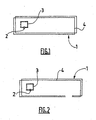
figure 1 est une représentation schématique d'un dispositif d'identification et de protection selon l'invention, l'élément étant intact. - La
figure 2 est une représentation schématique du dispositif de lafigure 1 , lorsque l'on a porté atteinte à l'intégrité de l'élément.
- The
figure 1 is a schematic representation of an identification and protection device according to the invention, the element being intact. - The
figure 2 is a schematic representation of the device of thefigure 1 when the integrity of the element has been compromised.
En référence à la
À des fins de simplification, on décrira le dispositif 1 associé à un élément dont l'état d'intégrité consiste à savoir si l'élément a été ouvert ou non.For purposes of simplification, the device 1 associated with an element whose state of integrity is to know whether the element has been opened or not is described.
Le dispositif 1 comprend une étiquette d'identification électronique 2 dont le contenu peut être lu à distance. L'étiquette 2 est par exemple du type puce RFID. Une batterie d'alimentation peut lui être associée afin de l'alimenter en énergie, on parle alors d'étiquette active. Selon une autre réalisation, l'alimentation en énergie de l'étiquette 2 peut être réalisée par l'intermédiaire du dispositif de lecture à distance agencé pour lire le contenu de l'étiquette. Dans ce cas, l'étiquette n'est pas associée à une batterie et l'étiquette est dite passive.The device 1 comprises an electronic identification tag 2 whose content can be read remotely. The label 2 is for example of the RFID chip type. A battery pack can be associated with it in order to supply it with energy, which is called an active label. According to another embodiment, the power supply of the tag 2 can be achieved by means of the remote reading device arranged to read the contents of the tag. In this case, the label is not associated with a battery and the label is said to be passive.
L'étiquette 2 est associée avec une première antenne 3. La première antenne 3 est agencée de sorte que le contenu de l'étiquette 2 peut être lu à distance par un dispositif de lecture. De même, du contenu peut être inscrit sur l'étiquette 2 par l'intermédiaire du dispositif de lecture qui est alors un dispositif de lecture/écriture.The tag 2 is associated with a
La première antenne 3 est par exemple associée électriquement avec l'étiquette 2, c'est-à-dire qu'il existe une connexion électrique entre l'antenne 3 et l'étiquette 2. Selon une autre réalisation, l'antenne 3 peut être couplée à l'étiquette 2 sans contact au moyen d'un couplage électromagnétique.The
La première antenne 3 est disposée à proximité de l'étiquette 2 sur l'une des parties de l'élément qui reste intègre si l'élément est ouvert. Par exemple dans le cas d'un récipient comprenant un corps et un bouchon, l'étiquette 2 et la première antenne 3 sont disposées intégralement sur le corps du récipient. De la sorte, on s'assure que l'on peut toujours lire le contenu de l'étiquette 2, même si l'on porte atteinte à l'intégrité de l'élément. La première antenne peut avoir différentes formes selon les réalisations et les contraintes de géométrie de l'élément avec lequel le dispositif 1 est destiné à être associé.The
Le dispositif 1 comprend en outre une deuxième antenne 4 couplée à la première antenne 3. Selon la réalisation représentée sur les figures, la deuxième antenne 4 est couplée par voie électromagnétique avec la première antenne 3, c'est-à-dire qu'il n'y a pas de contact électrique entre la première et la deuxième antennes: Le couplage électromagnétique consiste à accorder et à mettre en résonance les deux antennes afin de transmettre une modulation électromagnétique représentant le contenu de l'étiquette 2.The device 1 further comprises a
La deuxième antenne 4 est destinée à être disposée au moins en partie sur la partie de l'élément à laquelle on peut porter atteinte. Ainsi, dans le cas de l'élément comprenant un corps de récipient et un bouchon, la deuxième antenne 4 s'étend au moins en partie sur le bouchon. La deuxième antenne 4 peut présenter différentes formes selon les réalisations et les contraintes de géométrie de l'élément. Une contrainte de forme est également qu'il faut s'assurer que le couplage électromagnétique est assuré avec la première antenne 3.The
Selon la réalisation représentée sur les figures, la deuxième antenne 4 entoure la première antenne 3 et présente une dimension très supérieure à celle de la première antenne 3.According to the embodiment shown in the figures, the
En fonctionnement normal, lorsque l'élément n'a pas été ouvert ou que l'on n'a pas porté atteinte à son intégrité, le contenu de l'étiquette 2 peut être lu par l'intermédiaire de la deuxième antenne 4 et/ou de la première antenne 3. On obtient ainsi une information supplémentaire indiquant que l'élément a préservé son intégrité.In normal operation, when the element has not been opened or when its integrity has not been compromised, the content of the label 2 can be read via the
Selon la réalisation représentée sur les figures, lorsque la deuxième antenne 4 ne s'étend qu'en partie sur la partie de l'élément à laquelle on peut porter atteinte, la deuxième antenne 4 est agencée pour se rompre, comme représenté sur la
Outre la rupture de la deuxième antenne 4, on peut envisager selon les réalisations que la deuxième antenne 4 s'ouvre par dégradation du matériau dans lequel est réalisée l'antenne 4. Ainsi, si l'information d'intégrité consiste à savoir si l'élément a été maintenu dans une certaine plage de températures lors de son stockage, l'antenne 4 peut être réalisée dans un matériau se dégradant si l'on dépasse une température prédéfinie. Un matériau adapté à une telle utilisation est alors choisi. Si l'information d'intégrité consiste à savoir si une date de péremption n'a pas été dépassée, l'antenne 4 peut être réalisée dans un matériau se dégradant au bout d'un certain temps correspondant à cette date de péremption. De même, on peut prévoir d'autres matériaux pour l'antenne 4 en fonction de ce que l'on souhaite savoir sur l'intégrité de l'élément, par exemple une antenne se dégradant ou n'émettant plus en milieu aqueux, acide ou basique, etc.Apart from breaking the
Selon une autre réalisation, lorsque la deuxième antenne 4 s'étend en totalité sur la partie de l'élément à laquelle on peut porter atteinte, par exemple un couvercle qui peut être ouvert ou fermé, la deuxième antenne 4 s'écarte de la première antenne 3 et de l'étiquette 2 lorsque l'élément est ouvert. Le couplage électromagnétique entre les deux antennes est alors rompu et on ne peut lire le contenu de l'étiquette 2 que par l'intermédiaire de la première antenne 3. On obtient ainsi une information supplémentaire indiquant que l'on a porté atteinte à l'intégrité de l'élément.According to another embodiment, when the
Dans tous les cas, le contenu de l'étiquette 2 reste toujours lisible par la première antenne et ce contenu n'est pas perdu lorsque l'on porte atteinte à l'intégrité de l'élément.In all cases, the content of the label 2 is still readable by the first antenna and this content is not lost when the integrity of the element is compromised.
Selon d'autres réalisations, on peut prévoir d'autres antennes au-delà de la deuxième antenne 4. Ces antennes sont couplées les unes avec les autres et sont agencées pour les couplages soient rompus comme indiqué plus haut si l'on porte atteinte à l'intégrité de l'élément. On obtient ainsi plusieurs niveaux de protection de l'intégrité. On peut par exemple prévoir une antenne se dégradant en fonction de la température couplée à une antenne agencée pour se rompre en cas d'ouverture de l'élément, etc.According to other embodiments, it is possible to provide other antennas beyond the
On décrit à présent un ensemble d'identification et de protection comprenant un dispositif d'identification et de protection tel que décrit ci-dessus ainsi qu'un appareil de lecture/écriture de ce dispositif. L'appareil de lecture/écriture comprend une première tête de lecture agencée pour lire le signal émis par la première antenne 3. L'appareil comprend en outre au moins une deuxième tête de lecture agencée pour lire le signal émis par la deuxième antenne 4. L'appareil peut ainsi lire à la fois le signal émis par la première antenne 3 et celui émis par la deuxième antenne 4. L'appareil est agencé pour émettre un signal positif lorsque la lecture des signaux se fait sur les deux antennes et un signal négatif si la lecture des signaux se fait sur la première antenne 3 uniquement. Le signal positif est par exemple une diode s'illuminant lorsque les deux signaux sont lus et le signal négatif une diode ne s'illuminant pas. Le signal émis par l'appareil peut également être transféré à un système de traitement.An identification and protection assembly is now described comprising an identification and protection device as described above as well as a read / write device of this device. The read / write apparatus comprises a first read head arranged to read the signal transmitted by the
Selon une réalisation, l'appareil est agencé pour transmettre, par l'intermédiaire d'une tête d'écriture, le signal positif ou négatif à l'étiquette 2 afin d'inscrire l'information d'intégrité sur cette étiquette.In one embodiment, the apparatus is arranged to transmit, by means of a writing head, the positive or negative signal to the tag 2 in order to write the integrity information on this tag.
Claims (10)
- Identification and protection device intended to be combined with an element of which one wishes to know the integrity, the said device comprising an electronic identification tag (2) combined with a first aerial (3) arranged to allow the content of the tag (2) to be read at a distance, at least a second aerial (4) coupled with the first aerial (3), the said second aerial being arranged to allow the content of the tag (2) to be read at a distance, the said second aerial being intended to be combined with the element in such a way that the coupling between the first (3) and second aerial (4) is broken when the integrity of the said element is violated, characterised in that the coupling is broken on opening the second aerial (4) by degradation of the data of the said aerial by means of the nature of the surrounding area.
- Identification and protection device according to claim 1, characterised in that the tag (2) and the first aerial (3) are intended to be arranged on a section of the element of which the integrity is always maintained, the second aerial (4) extending at least partly on the section of the element of which the integrity can be violated.
- Identification and protection device according to claim 1 or 2, characterised in that the opening of the second aerial (4) is achieved by decryption of the said aerial.
- Identification and protection device according to claim 1 or 2, characterised in that the coupling is broken by distance between the second aerial (4) and the first aerial (3) when the integrity of the element is violated, the coupling between the aerials being able to be re-established by bringing the said aerials together.
- Identification and protection device according to any one of claims 1 to 4, characterised in that the first (3) and second aerial (4) are coupled electromagnetically without contact between the said aerials.
- Identification and protection device according to any one of claims 1 to 5, characterised in that the content of the tag (2) is read by means of the second aerial (4) and/or the first aerial (3) when the integrity of the element is not violated, and by means of the first aerial (3) only when the integrity of the said element has been violated.
- Identification and protection device according to any one of claims 1 to 6, characterised in that the identification tag (2) is connected to a battery powering the said tag.
- Identification and protection device according to any one of claims 1 to 6, characterised in that the electronic identification tag (2) is powered by means of the distance reading device arranged to read the content of the tag.
- Identification and protection assembly including an identification and protection device according to any one of claims 1 to 8, the said assembly being characterised in that it includes a reading/writing device, the said device comprising a first reading head arranged to read the signal emitted by the first aerial (3) and at least a second reading head arranged to read the signal emitted by the second aerial (4), the said device being arranged to emit a positive signal if reading the signals happens on the two aerials and a negative signal if reading the signals only happens on the first aerial (3).
- Identification and protection assembly according to claim 9, characterised in that the device is arranged to transmit, by means of a writing head, the positive or negative signal to the tag (2) in order to write the integrity information on the said tag.
Applications Claiming Priority (2)
| Application Number | Priority Date | Filing Date | Title |
|---|---|---|---|
| FR0510647A FR2892214B1 (en) | 2005-10-19 | 2005-10-19 | DEVICE FOR IDENTIFYING AND PROTECTING AN ELEMENT WHERE WE WISH TO KNOW THE INTEGRITY |
| PCT/FR2006/002350 WO2007045766A2 (en) | 2005-10-19 | 2006-10-19 | Device for identifying and protecting am element whose integrity is desired to be known |
Publications (2)
| Publication Number | Publication Date |
|---|---|
| EP1946251A2 EP1946251A2 (en) | 2008-07-23 |
| EP1946251B1 true EP1946251B1 (en) | 2012-03-28 |
Family
ID=36616517
Family Applications (1)
| Application Number | Title | Priority Date | Filing Date |
|---|---|---|---|
| EP06820239A Not-in-force EP1946251B1 (en) | 2005-10-19 | 2006-10-19 | Device for identifying and protecting an element whose integrity is desired to be known |
Country Status (7)
| Country | Link |
|---|---|
| US (1) | US20090102646A1 (en) |
| EP (1) | EP1946251B1 (en) |
| JP (1) | JP2009512926A (en) |
| AT (1) | ATE551665T1 (en) |
| CA (1) | CA2626597A1 (en) |
| FR (1) | FR2892214B1 (en) |
| WO (1) | WO2007045766A2 (en) |
Families Citing this family (4)
| Publication number | Priority date | Publication date | Assignee | Title |
|---|---|---|---|---|
| FR2915822A1 (en) * | 2007-05-03 | 2008-11-07 | Pygmalyon Sa | Passive and resonating type radiofrequency detection or identification tag for object carrier, has closed loops corresponding to wavelength to be transmitted, where loops are placed close to each other to establish coupling between loops |
| CN102027516A (en) * | 2008-04-25 | 2011-04-20 | 国际密封系统公司 | Anti-counterfeiting system |
| US9697711B2 (en) * | 2015-03-19 | 2017-07-04 | The Boeing Company | System and method for tamper detection using RFID devices |
| DE102015003837B4 (en) * | 2015-03-25 | 2017-11-23 | Dietrich Fischer | Method and system for counterfeiting |
Family Cites Families (3)
| Publication number | Priority date | Publication date | Assignee | Title |
|---|---|---|---|---|
| FI95523C (en) * | 1993-11-30 | 1996-02-12 | Idesco Oy | Remotely readable sensor design |
| JP2000172812A (en) * | 1998-12-08 | 2000-06-23 | Hitachi Maxell Ltd | Noncontact information medium |
| FR2840431B1 (en) * | 2002-05-29 | 2004-09-03 | Francois Trantoul | METHOD AND DEVICE FOR PROTECTING READING INSTRUCTIONS |
-
2005
- 2005-10-19 FR FR0510647A patent/FR2892214B1/en not_active Expired - Fee Related
-
2006
- 2006-10-19 US US12/091,007 patent/US20090102646A1/en not_active Abandoned
- 2006-10-19 EP EP06820239A patent/EP1946251B1/en not_active Not-in-force
- 2006-10-19 CA CA002626597A patent/CA2626597A1/en not_active Abandoned
- 2006-10-19 WO PCT/FR2006/002350 patent/WO2007045766A2/en active Application Filing
- 2006-10-19 JP JP2008536085A patent/JP2009512926A/en active Pending
- 2006-10-19 AT AT06820239T patent/ATE551665T1/en active
Also Published As
| Publication number | Publication date |
|---|---|
| US20090102646A1 (en) | 2009-04-23 |
| WO2007045766A2 (en) | 2007-04-26 |
| ATE551665T1 (en) | 2012-04-15 |
| WO2007045766A3 (en) | 2007-06-14 |
| EP1946251A2 (en) | 2008-07-23 |
| FR2892214B1 (en) | 2008-02-15 |
| CA2626597A1 (en) | 2007-04-26 |
| JP2009512926A (en) | 2009-03-26 |
| FR2892214A1 (en) | 2007-04-20 |
Similar Documents
| Publication | Publication Date | Title |
|---|---|---|
| US11288565B2 (en) | Non-transferable radio frequency identification label or tag | |
| EP2507747B1 (en) | Activation and indication of an rf field on a device including a chip | |
| EP0617826B1 (en) | Security sealing device | |
| EP1946251B1 (en) | Device for identifying and protecting an element whose integrity is desired to be known | |
| EP1511909B9 (en) | Multipurpose seal with lock and method of manufacturing a multipurpose seal | |
| EP0573320A1 (en) | System for automatic identification and detection of vehicles and objects | |
| JP2005182880A (en) | Tape cartridge | |
| US20110102153A1 (en) | Document including an integrated microcircuit device and a method of detecting an attack on the physical integrity of the document | |
| JP5122308B2 (en) | Coin-type storage media | |
| US20110140830A1 (en) | Temperature Tracking Device and Method Using Same | |
| EP0681549B1 (en) | System for identifying, searching for and locating objects | |
| CA2687736A1 (en) | Flexible adhesive label for security furnished with at least one contactless microcircuit for an official document | |
| EP2107532B1 (en) | Device to probe for secure data relating to the driving of a vehicle | |
| WO2002069250A1 (en) | Number plate authentication device | |
| AU761006B2 (en) | Method for protecting the identity of objects and device for performing the method | |
| WO2009098670A2 (en) | Tamper evident seal | |
| CN201149751Y (en) | ID code radio frequency lock-sealing apparatus | |
| CN201188289Y (en) | ID code radio frequency lock | |
| FR3047591A1 (en) | A TRACEABILITY SYSTEM FOR A GOODS COMPRISING A LABEL FOR INDICATING THAT AT LEAST ONE TEMPERATURE THRESHOLD HAS BEEN REACHED AND / OR EXCEEDED BY MEANS OF RADIO-IDENTIFICATION | |
| FR3095531A1 (en) | Guarantee and test label for a biometric sensor, electronic device such as a smart card, manufacturing and testing processes | |
| FR2968803A1 (en) | Electromagnetic transponder e.g. dual integrated circuit card, for contactless exchanging of protected data with reader for bank card, has electric circuit switched from one state to another state when resonant circuit is powered by reader | |
| JP3099594U (en) | Radio wave shielding packaging for sending non-contact type IC cards | |
| KR20030064067A (en) | Auto gate management system with rf-id label and method thereof | |
| WO2017064386A1 (en) | Cylinder of pressurised fluid and drawing or filling device |
Legal Events
| Date | Code | Title | Description |
|---|---|---|---|
| PUAI | Public reference made under article 153(3) epc to a published international application that has entered the european phase |
Free format text: ORIGINAL CODE: 0009012 |
|
| 17P | Request for examination filed |
Effective date: 20080505 |
|
| AK | Designated contracting states |
Kind code of ref document: A2 Designated state(s): AT BE BG CH CY CZ DE DK EE ES FI FR GB GR HU IE IS IT LI LT LU LV MC NL PL PT RO SE SI SK TR |
|
| 17Q | First examination report despatched |
Effective date: 20081111 |
|
| GRAP | Despatch of communication of intention to grant a patent |
Free format text: ORIGINAL CODE: EPIDOSNIGR1 |
|
| DAX | Request for extension of the european patent (deleted) | ||
| GRAS | Grant fee paid |
Free format text: ORIGINAL CODE: EPIDOSNIGR3 |
|
| GRAL | Information related to payment of fee for publishing/printing deleted |
Free format text: ORIGINAL CODE: EPIDOSDIGR3 |
|
| GRAS | Grant fee paid |
Free format text: ORIGINAL CODE: EPIDOSNIGR3 |
|
| GRAL | Information related to payment of fee for publishing/printing deleted |
Free format text: ORIGINAL CODE: EPIDOSDIGR3 |
|
| GRAS | Grant fee paid |
Free format text: ORIGINAL CODE: EPIDOSNIGR3 |
|
| GRAA | (expected) grant |
Free format text: ORIGINAL CODE: 0009210 |
|
| AK | Designated contracting states |
Kind code of ref document: B1 Designated state(s): AT BE BG CH CY CZ DE DK EE ES FI FR GB GR HU IE IS IT LI LT LU LV MC NL PL PT RO SE SI SK TR |
|
| REG | Reference to a national code |
Ref country code: GB Ref legal event code: FG4D Free format text: NOT ENGLISH |
|
| REG | Reference to a national code |
Ref country code: CH Ref legal event code: EP |
|
| REG | Reference to a national code |
Ref country code: AT Ref legal event code: REF Ref document number: 551665 Country of ref document: AT Kind code of ref document: T Effective date: 20120415 |
|
| REG | Reference to a national code |
Ref country code: IE Ref legal event code: FG4D Free format text: LANGUAGE OF EP DOCUMENT: FRENCH |
|
| REG | Reference to a national code |
Ref country code: DE Ref legal event code: R096 Ref document number: 602006028517 Country of ref document: DE Effective date: 20120606 |
|
| REG | Reference to a national code |
Ref country code: NL Ref legal event code: VDEP Effective date: 20120328 |
|
| PG25 | Lapsed in a contracting state [announced via postgrant information from national office to epo] |
Ref country code: LT Free format text: LAPSE BECAUSE OF FAILURE TO SUBMIT A TRANSLATION OF THE DESCRIPTION OR TO PAY THE FEE WITHIN THE PRESCRIBED TIME-LIMIT Effective date: 20120328 |
|
| LTIE | Lt: invalidation of european patent or patent extension |
Effective date: 20120328 |
|
| PG25 | Lapsed in a contracting state [announced via postgrant information from national office to epo] |
Ref country code: GR Free format text: LAPSE BECAUSE OF FAILURE TO SUBMIT A TRANSLATION OF THE DESCRIPTION OR TO PAY THE FEE WITHIN THE PRESCRIBED TIME-LIMIT Effective date: 20120629 Ref country code: LV Free format text: LAPSE BECAUSE OF FAILURE TO SUBMIT A TRANSLATION OF THE DESCRIPTION OR TO PAY THE FEE WITHIN THE PRESCRIBED TIME-LIMIT Effective date: 20120328 Ref country code: FI Free format text: LAPSE BECAUSE OF FAILURE TO SUBMIT A TRANSLATION OF THE DESCRIPTION OR TO PAY THE FEE WITHIN THE PRESCRIBED TIME-LIMIT Effective date: 20120328 |
|
| REG | Reference to a national code |
Ref country code: AT Ref legal event code: MK05 Ref document number: 551665 Country of ref document: AT Kind code of ref document: T Effective date: 20120328 |
|
| PG25 | Lapsed in a contracting state [announced via postgrant information from national office to epo] |
Ref country code: CY Free format text: LAPSE BECAUSE OF FAILURE TO SUBMIT A TRANSLATION OF THE DESCRIPTION OR TO PAY THE FEE WITHIN THE PRESCRIBED TIME-LIMIT Effective date: 20120328 |
|
| PG25 | Lapsed in a contracting state [announced via postgrant information from national office to epo] |
Ref country code: PL Free format text: LAPSE BECAUSE OF FAILURE TO SUBMIT A TRANSLATION OF THE DESCRIPTION OR TO PAY THE FEE WITHIN THE PRESCRIBED TIME-LIMIT Effective date: 20120328 Ref country code: EE Free format text: LAPSE BECAUSE OF FAILURE TO SUBMIT A TRANSLATION OF THE DESCRIPTION OR TO PAY THE FEE WITHIN THE PRESCRIBED TIME-LIMIT Effective date: 20120328 Ref country code: IS Free format text: LAPSE BECAUSE OF FAILURE TO SUBMIT A TRANSLATION OF THE DESCRIPTION OR TO PAY THE FEE WITHIN THE PRESCRIBED TIME-LIMIT Effective date: 20120728 Ref country code: SI Free format text: LAPSE BECAUSE OF FAILURE TO SUBMIT A TRANSLATION OF THE DESCRIPTION OR TO PAY THE FEE WITHIN THE PRESCRIBED TIME-LIMIT Effective date: 20120328 Ref country code: RO Free format text: LAPSE BECAUSE OF FAILURE TO SUBMIT A TRANSLATION OF THE DESCRIPTION OR TO PAY THE FEE WITHIN THE PRESCRIBED TIME-LIMIT Effective date: 20120328 Ref country code: SE Free format text: LAPSE BECAUSE OF FAILURE TO SUBMIT A TRANSLATION OF THE DESCRIPTION OR TO PAY THE FEE WITHIN THE PRESCRIBED TIME-LIMIT Effective date: 20120328 |
|
| PG25 | Lapsed in a contracting state [announced via postgrant information from national office to epo] |
Ref country code: PT Free format text: LAPSE BECAUSE OF FAILURE TO SUBMIT A TRANSLATION OF THE DESCRIPTION OR TO PAY THE FEE WITHIN THE PRESCRIBED TIME-LIMIT Effective date: 20120730 Ref country code: SK Free format text: LAPSE BECAUSE OF FAILURE TO SUBMIT A TRANSLATION OF THE DESCRIPTION OR TO PAY THE FEE WITHIN THE PRESCRIBED TIME-LIMIT Effective date: 20120328 |
|
| PG25 | Lapsed in a contracting state [announced via postgrant information from national office to epo] |
Ref country code: DK Free format text: LAPSE BECAUSE OF FAILURE TO SUBMIT A TRANSLATION OF THE DESCRIPTION OR TO PAY THE FEE WITHIN THE PRESCRIBED TIME-LIMIT Effective date: 20120328 Ref country code: AT Free format text: LAPSE BECAUSE OF FAILURE TO SUBMIT A TRANSLATION OF THE DESCRIPTION OR TO PAY THE FEE WITHIN THE PRESCRIBED TIME-LIMIT Effective date: 20120328 Ref country code: CZ Free format text: LAPSE BECAUSE OF FAILURE TO SUBMIT A TRANSLATION OF THE DESCRIPTION OR TO PAY THE FEE WITHIN THE PRESCRIBED TIME-LIMIT Effective date: 20120328 Ref country code: NL Free format text: LAPSE BECAUSE OF FAILURE TO SUBMIT A TRANSLATION OF THE DESCRIPTION OR TO PAY THE FEE WITHIN THE PRESCRIBED TIME-LIMIT Effective date: 20120328 |
|
| PGFP | Annual fee paid to national office [announced via postgrant information from national office to epo] |
Ref country code: FR Payment date: 20121204 Year of fee payment: 7 |
|
| PLBE | No opposition filed within time limit |
Free format text: ORIGINAL CODE: 0009261 |
|
| STAA | Information on the status of an ep patent application or granted ep patent |
Free format text: STATUS: NO OPPOSITION FILED WITHIN TIME LIMIT |
|
| PG25 | Lapsed in a contracting state [announced via postgrant information from national office to epo] |
Ref country code: IT Free format text: LAPSE BECAUSE OF FAILURE TO SUBMIT A TRANSLATION OF THE DESCRIPTION OR TO PAY THE FEE WITHIN THE PRESCRIBED TIME-LIMIT Effective date: 20120328 |
|
| 26N | No opposition filed |
Effective date: 20130103 |
|
| REG | Reference to a national code |
Ref country code: DE Ref legal event code: R097 Ref document number: 602006028517 Country of ref document: DE Effective date: 20130103 |
|
| BERE | Be: lapsed |
Owner name: BARA, NICOLAS Effective date: 20121031 Owner name: LO-RE, BRUNO Effective date: 20121031 |
|
| PG25 | Lapsed in a contracting state [announced via postgrant information from national office to epo] |
Ref country code: ES Free format text: LAPSE BECAUSE OF FAILURE TO SUBMIT A TRANSLATION OF THE DESCRIPTION OR TO PAY THE FEE WITHIN THE PRESCRIBED TIME-LIMIT Effective date: 20120709 |
|
| PG25 | Lapsed in a contracting state [announced via postgrant information from national office to epo] |
Ref country code: MC Free format text: LAPSE BECAUSE OF NON-PAYMENT OF DUE FEES Effective date: 20121031 |
|
| REG | Reference to a national code |
Ref country code: CH Ref legal event code: PL |
|
| GBPC | Gb: european patent ceased through non-payment of renewal fee |
Effective date: 20121019 |
|
| REG | Reference to a national code |
Ref country code: IE Ref legal event code: MM4A |
|
| PG25 | Lapsed in a contracting state [announced via postgrant information from national office to epo] |
Ref country code: GB Free format text: LAPSE BECAUSE OF NON-PAYMENT OF DUE FEES Effective date: 20121019 Ref country code: BE Free format text: LAPSE BECAUSE OF NON-PAYMENT OF DUE FEES Effective date: 20121031 Ref country code: LI Free format text: LAPSE BECAUSE OF NON-PAYMENT OF DUE FEES Effective date: 20121031 Ref country code: BG Free format text: LAPSE BECAUSE OF FAILURE TO SUBMIT A TRANSLATION OF THE DESCRIPTION OR TO PAY THE FEE WITHIN THE PRESCRIBED TIME-LIMIT Effective date: 20120628 Ref country code: IE Free format text: LAPSE BECAUSE OF NON-PAYMENT OF DUE FEES Effective date: 20121019 Ref country code: DE Free format text: LAPSE BECAUSE OF NON-PAYMENT OF DUE FEES Effective date: 20130501 Ref country code: CH Free format text: LAPSE BECAUSE OF NON-PAYMENT OF DUE FEES Effective date: 20121031 |
|
| REG | Reference to a national code |
Ref country code: DE Ref legal event code: R119 Ref document number: 602006028517 Country of ref document: DE Effective date: 20130501 |
|
| REG | Reference to a national code |
Ref country code: FR Ref legal event code: TP Owner name: MAINTAG, FR Effective date: 20130910 |
|
| PG25 | Lapsed in a contracting state [announced via postgrant information from national office to epo] |
Ref country code: TR Free format text: LAPSE BECAUSE OF FAILURE TO SUBMIT A TRANSLATION OF THE DESCRIPTION OR TO PAY THE FEE WITHIN THE PRESCRIBED TIME-LIMIT Effective date: 20120328 |
|
| PG25 | Lapsed in a contracting state [announced via postgrant information from national office to epo] |
Ref country code: LU Free format text: LAPSE BECAUSE OF NON-PAYMENT OF DUE FEES Effective date: 20121019 |
|
| PG25 | Lapsed in a contracting state [announced via postgrant information from national office to epo] |
Ref country code: HU Free format text: LAPSE BECAUSE OF FAILURE TO SUBMIT A TRANSLATION OF THE DESCRIPTION OR TO PAY THE FEE WITHIN THE PRESCRIBED TIME-LIMIT Effective date: 20061019 |
|
| REG | Reference to a national code |
Ref country code: FR Ref legal event code: ST Effective date: 20140630 |
|
| PG25 | Lapsed in a contracting state [announced via postgrant information from national office to epo] |
Ref country code: FR Free format text: LAPSE BECAUSE OF NON-PAYMENT OF DUE FEES Effective date: 20131031 |