EP1946136B1 - Resonator system for use during magnetic resonance imaging - Google Patents
Resonator system for use during magnetic resonance imaging Download PDFInfo
- Publication number
- EP1946136B1 EP1946136B1 EP06817389.7A EP06817389A EP1946136B1 EP 1946136 B1 EP1946136 B1 EP 1946136B1 EP 06817389 A EP06817389 A EP 06817389A EP 1946136 B1 EP1946136 B1 EP 1946136B1
- Authority
- EP
- European Patent Office
- Prior art keywords
- capacitance
- adjustable capacitance
- magnetic field
- resonator
- processor
- Prior art date
- Legal status (The legal status is an assumption and is not a legal conclusion. Google has not performed a legal analysis and makes no representation as to the accuracy of the status listed.)
- Not-in-force
Links
- 238000002595 magnetic resonance imaging Methods 0.000 title claims description 53
- 230000003068 static effect Effects 0.000 claims description 28
- 239000003990 capacitor Substances 0.000 claims description 27
- 230000004044 response Effects 0.000 claims description 19
- 239000004020 conductor Substances 0.000 description 14
- 125000004435 hydrogen atom Chemical group [H]* 0.000 description 11
- 238000012800 visualization Methods 0.000 description 9
- 230000006870 function Effects 0.000 description 7
- 238000004804 winding Methods 0.000 description 4
- 230000005684 electric field Effects 0.000 description 3
- 230000005672 electromagnetic field Effects 0.000 description 3
- 230000002708 enhancing effect Effects 0.000 description 3
- 238000000034 method Methods 0.000 description 3
- 238000006842 Henry reaction Methods 0.000 description 2
- RYGMFSIKBFXOCR-UHFFFAOYSA-N Copper Chemical compound [Cu] RYGMFSIKBFXOCR-UHFFFAOYSA-N 0.000 description 1
- 229910000881 Cu alloy Inorganic materials 0.000 description 1
- 229910052802 copper Inorganic materials 0.000 description 1
- 239000010949 copper Substances 0.000 description 1
- 230000001419 dependent effect Effects 0.000 description 1
- 230000010339 dilation Effects 0.000 description 1
- 229940079593 drug Drugs 0.000 description 1
- 239000003814 drug Substances 0.000 description 1
- 239000007943 implant Substances 0.000 description 1
- 230000006698 induction Effects 0.000 description 1
- 239000000463 material Substances 0.000 description 1
- 230000001902 propagating effect Effects 0.000 description 1
Images
Classifications
-
- G—PHYSICS
- G01—MEASURING; TESTING
- G01R—MEASURING ELECTRIC VARIABLES; MEASURING MAGNETIC VARIABLES
- G01R33/00—Arrangements or instruments for measuring magnetic variables
- G01R33/20—Arrangements or instruments for measuring magnetic variables involving magnetic resonance
- G01R33/28—Details of apparatus provided for in groups G01R33/44 - G01R33/64
- G01R33/285—Invasive instruments, e.g. catheters or biopsy needles, specially adapted for tracking, guiding or visualization by NMR
- G01R33/286—Invasive instruments, e.g. catheters or biopsy needles, specially adapted for tracking, guiding or visualization by NMR involving passive visualization of interventional instruments, i.e. making the instrument visible as part of the normal MR process
-
- G—PHYSICS
- G01—MEASURING; TESTING
- G01R—MEASURING ELECTRIC VARIABLES; MEASURING MAGNETIC VARIABLES
- G01R33/00—Arrangements or instruments for measuring magnetic variables
- G01R33/20—Arrangements or instruments for measuring magnetic variables involving magnetic resonance
- G01R33/28—Details of apparatus provided for in groups G01R33/44 - G01R33/64
- G01R33/32—Excitation or detection systems, e.g. using radio frequency signals
- G01R33/36—Electrical details, e.g. matching or coupling of the coil to the receiver
- G01R33/3628—Tuning/matching of the transmit/receive coil
Definitions
- the present disclosure relates generally to medical device systems; and more particularly to medical device systems for use during magnetic resonance imaging.
- Magnetic resonance imaging can create images of internal aspects of structures by using magnetic fields of various field strengths.
- MRI Magnetic resonance imaging
- An LC circuit can form a basis for a resonator device.
- An LC circuit with a fixed inductance and a fixed capacitance can resonate at a particular frequency.
- an MRI can use magnetic fields with a range of field strengths to cause material in a structure or an object to resonate over a range of frequencies.
- a resonator device with a fixed inductance and a fixed capacitance may not resonate over a range of frequencies.
- Document DE-A-101 27 850 discloses a resonator system for use during magnetic resonance imaging, comprising a gastroscope and a resonator circuit that includes an inductor coil in series with an adjustable capacitance.
- the inductor coil surrounds a space that is surrounded by a portion of the gastroscope.
- a matching box is provided for adjusting the resonant frequency of the resonator circuit.
- the present invention relates to a resonator system for use during magnetic resonance imaging according to claim 1. Preferred embodiments are described in dependent claims 2 to 5.
- Embodiments of the present disclosure are directed to resonator systems.
- a resonator device can be used in conjunction with a medical device, including a deliverable device, deliverable in a lumen of a body.
- a medical device including a deliverable device, deliverable in a lumen of a body.
- One embodiment of the present disclosure includes a resonator with an adjustable capacitance for a medical device, which can enhance visualization when performing MRI.
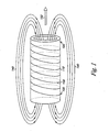
- Figure 1 illustrates an exemplary embodiment of an MRI machine and a static magnetic field.
- Figure 1 is intended to illustrate basic concepts of an MRI machine and is not intended to show details of an MRI machine or to illustrate a particular MRI machine.
- Figure 1 includes an MRI scanner 110 with a coil 130 and terminals 120.
- Figure 1 also includes static magnetic field lines 140 and a magnetic field vector 150.
- the MRI scanner 110 is a cylindrical tube.
- the coil 130 is electrically conductive.
- the coil 130 begins at one terminal 120, winds around the MRI scanner 110 in helical form, and ends at another terminal 120.
- Each terminal 120 is connected to the coil 130 so that electrical current can flow from the terminal 120 through the coil 130.
- each of the static magnetic field lines 140 has a direction, which is represented by arrows. The direction of the magnetic field lines 140 can depend upon the direction in which electrical current flows through the coil 130.
- the static magnetic field also has a magnetic field vector 150.
- the magnetic field vector 150 coincides with a central axis of the MRI scanner 110.
- the magnetic field vector 150 also has a direction which can depend upon the direction in which electrical current flows through the coil 130.
- the static magnetic field can cause hydrogen protons within the field to align with the magnetic field vector 150.
- the magnetic field vector 150 can also serve as a reference direction when performing MRI, as described in Figures 2A and 2B .
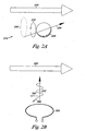
- Figure 2A illustrates an exemplary embodiment of a hydrogen proton in a static magnetic field of an MRI machine.
- Figure 2A includes a magnetic field vector 250 and an illustration of a precessing hydrogen proton 230.
- the magnetic field vector 250 corresponds with a static magnetic field of an MRI machine, such as the static magnetic field of Figure 1 .
- the illustration of the precessing hydrogen proton 230 includes a hydrogen proton 238, a spin direction 232, a reference arrow 234, and a reference circle 236.
- the presence of the static magnetic field causes the hydrogen proton 238 to precess in the spin direction 232.
- the hydrogen proton 238 precesses in the spin direction 232 around an axis that is parallel to the magnetic field vector 250.
- the reference arrow 234 indicates that the precessing of the hydrogen proton 238 creates the reference circle 236.
- the magnetic field vector 250 is perpendicular to the reference circle 236.
- Figure 2B illustrates an exemplary embodiment of a radio-frequency pulse in relation to a static magnetic field of an MRI machine.
- Figure 2B includes a magnetic field vector 250, a transmitter coil 260, a radio frequency (RF) pulse 270, an RF pulse magnetic field vector 280, and an RF pulse electrical field vector 290.
- the magnetic field vector 250 corresponds with a static magnetic field of an MRI machine, such as the static magnetic field of Figure 1 .
- the transmitter coil 260 can be part of the MRI machine and can create the RF pulse 270.
- the RF pulse 270 can be an oscillating electro-magnetic field, propagating in a direction perpendicular to the magnetic field vector 250.
- the RF pulse 270 includes the RF pulse magnetic field vector 280 and the RF pulse electrical field vector 290.
- RF pulse magnetic field vector 280 and the RF pulse electrical field vector 290 can be perpendicular to each other and perpendicular to the direction in which the RF pulse 270 propagates.
- An MRI machine can create an RF pulse at a certain frequency called the Larmor frequency.
- the Larmor frequency is a frequency at which certain protons resonate.
- the Larmor frequency differs for protons of different elements and for static magnetic fields of different strengths.
- Many MRI machines create RF pulses for hydrogen protons, and this is assumed throughout this document unless otherwise indicated.
- the Larmor frequency is 42.9 MHz for each Tesla of static magnetic field strength.
- Some MRI machines can create static magnetic fields with a magnetic field strength ranging from 0.3 Teslas to 7.0 Teslas. Many MRI machines create static magnetic fields with a magnetic field strength ranging from 1.5 Teslas to 3.0 Teslas. Thus, MRI machines that create static magnetic fields with a magnetic field strength between 0.3 and 7.0 Teslas operate at Larmor frequencies between 13 and 300 MHz. Similarly, MRI machines that create static magnetic fields with a magnetic field strength between 1.5 and 3.0 Teslas operate at Larmor frequencies between 64 and 129 MHz.
- a resonator device can enhance visualization of images by resonating at the Larmor frequency. In some instances, a resonator device can enhance visualization of images by resonating at a frequency close to a Larmor frequency, depending on the frequency response of the device.
- a resonator device based on an LC circuit with a fixed inductance and a fixed capacitance may not resonate over a range of frequencies. Additionally, an inductance of an LC circuit may change under certain conditions or may change in certain applications, such as an inductor coil with a radius that changes when used with an expandable stent.
- a resonator device can be used with a balloon expandable stent or a self-expandable stent. However, a resonator device with an adjustable capacitance can resonate over a range of frequencies, as described in Figures 3A and 3B .
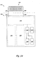
- Figure 3A illustrates an embodiment of a resonator device with an adjustable capacitance according to the present disclosure.
- the resonator device 301 includes an inductor coil 304, connecting conductors 306, and a circuit package 308.
- the connecting conductors 306 are shown as broken lines to indicate that the inductor coil 304 and the circuit package 308 as shown, may have different scales.
- the sizes of elements in the Figure 3A are merely illustrative and are not intended to indicate any particular size or relationship in size.
- the inductor coil 304 is external to the circuit package 308, in the resonator device 301.
- the circuit package 308 encapsulates electrical components, including sensors 310, an adjustable capacitance 320, and an adjustable capacitance control 330.
- the inductor coil 304, the connecting conductors 306, at least a portion of the adjustable capacitance 320, and at least a portion of the adjustable capacitance control 330 together form an LC resonator circuit.
- the circuit package also encapsulates a processor 360, a memory, 370, a power source 380, and a selector 390, which relate to the LC resonator circuit, as described herein.
- the adjustable capacitance 320 can have different particular capacitance values.
- the adjustable capacitance 320 as a whole, is electrically in series with the inductor coil 304.
- the inductor coil 304 and the adjustable capacitance 320 respectively form L and C components of the LC resonator circuit, as will be understood by one of ordinary skill in the art.
- the adjustable capacitance 320 is electrically connected to the adjustable capacitance control 330.
- the processor 360 is connected to the LC resonator circuit through the adjustable capacitance control 330.
- the processor 360 executes logic and/or program instructions that allow it to perform functions, including a function of adjusting the adjustable capacitance 320 by directing the adjustable capacitance control 330.
- the processor 360 directs the adjustable capacitance control 330 to control the adjustable capacitance 320 to obtain different particular capacitance values. Since the processor 360 directs the adjustable capacitance control 330, in various embodiments, the processor 360 can also be considered as part of the adjustable capacitance control 330.
- the processor 360 is also connected to the sensors 310.
- Figure 3A does not show details of the sensors 310, the adjustable capacitance 320, or the adjustable capacitance control 330. These details are described in Figure 3B .
- the processor 360 is also connected to the memory 370, the power source 380, and the selector 390.
- the memory 370 can store data which can be used by the processor 360.
- the processor 360 can communicate with the memory 370 through its connection to the memory 370.
- the power source 380 can provide the processor 360 with electrical power so the processor 360 can perform its functions, as described in Figure 2 .
- the selector 390 can be set to different settings, which represent various user inputs, as described herein.
- the power source 380 can have different forms in various embodiments.
- the power source 380 can generate electrical power from an electro-magnetic field.
- the power source 380 can be the inductor coil 304, another conducting coil, or a secondary resonator circuit.
- the powering electro-magnetic field can be an RF pulse from an MRI machine or some other field.
- an RF pulse can provide power over longer distances.
- the power source 380 can be a battery or a rechargeable capacitor.
- the power source 380 can also generate electrical power from an alternating magnetic field, such as a field within a transformer, for powering by induction over shorter distances.
- the processor 360 of Figure 3A automatically adjusts the adjustable capacitance 320 of the LC resonator circuit to a resonant capacitance, in response to an RF pulse from an MRI machine.
- the processor 360 performs this automatic adjustment by determining a resonant capacitance and then adjusting the adjustable capacitance 320 to the resonant capacitance.
- the resonant capacitance is a capacitance at which the LC resonator circuit will resonate in response to the RF pulse, as will be understood by one of ordinary skill in the art.
- the processor 360 directs this adjustment in various ways by executing logic and/or program instructions in response to known, sensed, and/or calculated values, as described in Figure 3B .
- a range of adjustable capacitance for an LC resonator circuit of a resonating device can be estimated, based upon a potential range of MRI Larmor frequencies of and an estimated range of inductor coil inductances.
- a potential range of MRI Larmor frequencies can be determined as described above.
- An estimated range of inductor coil inductances can be estimated by mathematically modeling an ideal inductance coil.
- An inductance for an ideal inductance coil can be mathematically modeled by using an ideal inductor formula.
- L ( ⁇ * N 2 * ⁇ * r 2 ) / 1
- L inductance in Henries
- ⁇ is a factor equal to 1.26 x 10 -7 Henries per meter
- N is a number of windings in an inductor coil
- r is a radius of the inductor coil in meters
- 1 is a length of the inductor coil in meters.
- the ideal inductor formula can be used to mathematically model an inductance for an ideal inductor coil sized to match various dimensions of a stent.
- a stent can range in radius from 0.001 meters to .005 meters and in length from 0.008 meters to 0.07 meters.
- an inductor can have 1 winding for every 0.001 meter of inductor length or 1 winding for every 0.002 meter of inductor length. Using these example numbers for an ideal inductance coil yields an estimated range of inductor coil inductances from 0.79 nanoHenries to 0.69 microHenries.
- a range of adjustable capacitance for an LC resonator circuit of a resonating device can be estimated, based upon a potential range of MRI Larmor frequencies, a potential range of inductor coil inductances and an LC circuit resonance formula.
- f 1 / (2 * ⁇ * ⁇ (L *C ) ) where f is a resonant frequency of the LC resonator circuit, L is an inductance of the LC resonator circuit at the resonant frequency, and C is the capacitance of the LC resonator circuit at the resonant frequency.
- the LC circuit resonance formula can be solved for a range of adjustable capacitance.
- a potential range of MRI Larmor frequencies from 13 to 300 MHz and a potential range of inductor coil inductances from 0.79 nanoHenries to 0.69 microHenries in the LC circuit resonance formula yields an estimated range of adjustable capacitance from 0.41 picoFarads to 0.19 microFarads, which can be created as described in Figure 3B .
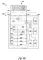
- Figure 3B illustrates another embodiment of a resonator device with an adjustable capacitance according to the present disclosure.
- the embodiment of Figure 3B is a specific embodiment of Figure 3A and includes elements corresponding with elements of the embodiment of Figure 3A .
- the resonator device 302 includes the inductor coil 304, the connecting conductors 306, and the circuit package 308.
- the sizes of elements in Figure 3B are merely illustrative and are not intended to indicate any particular size or relationship of size.
- the inductor coil 304 is external to the circuit package 308, in the resonator device 302.
- the circuit package 308 encapsulates electrical components, including the sensors 310, the adjustable capacitance 320, and the adjustable capacitance control 330.
- the inductor coil 304, the connecting conductors 306, at least a portion of the adjustable capacitance 320, and at least a portion of the adjustable capacitance control 330 together form an LC resonator circuit.
- the circuit package also encapsulates a processor 360, a memory, 370, a power source 380, and a selector 390, which relate to the LC resonator circuit, as described herein.
- the adjustable capacitance 320 includes a varactor 321, and capacitors 322, 324, 326, and 329.
- the varactor 321, and the capacitors 322, 324, 326, and 329 are electrically connected parallel to each other.
- the adjustable capacitance 320 can have different particular capacitance values based on the capacitance value of the varactor 321, the capacitance values of the capacitors 322, 324, 326, and 329, and the adjustable capacitance control 330, as described herein.
- the adjustable capacitance 320 is electrically in series with the inductor coil 304.
- One side of the inductor coil 304 is electrically connected to one side of the adjustable capacitance 320 through one of the connecting conductors 306.
- Another side of the inductor coil 304 is electrically connected to another side of the adjustable capacitance 320 through another of the connecting conductors 306 and through the adjustable capacitance control 330.
- the varactor 321, and the capacitors 322, 324, 326, and 329 are electrically parallel to each other, the adjustable capacitance 320, with its particular capacitance value, is electrically in series with the inductor coil 304.
- the inductor coil 304 and the adjustable capacitance 320 respectively form L and C components of the LC resonator circuit, as will be understood by one of ordinary skill in the art.
- the adjustable capacitance 320 is electrically connected to the adjustable capacitance control 330.
- the adjustable capacitance control 330 includes a varactor controller 331, and electrical switches 332, 334, 336, and 339.
- the varactor controller 331 controls an adjustable capacitance of the varactor 321.
- Each of the electrical switches 332, 334, 336, and 339 has an open state and a closed state. In the closed state, an electrical switch forms an electrical connection that allows electrical current to flow through that switch. In the open state, an electrical switch forms an electrical break that prevents electrical current from flowing through that switch.
- Each of the electrical switches of Figure 3B is shown in the open state, so the locations of the switches can be clearly identified.
- each electrical switch can connect its corresponding capacitor to the LC resonator circuit or disconnect its corresponding capacitor from the LC resonator circuit, depending on the state of the switch. For example, if the electrical switch 332 is in its closed state, it connects the capacitor 322 to the LC resonator circuit. Alternatively, if the electrical switch 332 is in its open state, then the capacitor 322 is disconnected from the LC resonator circuit.
- each electrical switch can connect or disconnect its corresponding capacitor individually.
- the adjustable capacitance 320 can be adjusted to different particular capacitance values depending on which capacitors are connected to the LC resonator circuit.
- the LC resonator circuit is electrically connected to some of the sensors 310.
- the sensors 310 include a voltage sensor 312, a current sensor 314, and a magnetic field strength sensor 316.
- some of the sensors 310 are electrically connected to the LC resonator circuit and each of the sensors 310 are connected to the processor 360.
- the voltage sensor 312 is electrically connected across the adjustable capacitance 312 and can sense an electrical voltage differential across the adjustable capacitance 312.
- the voltage sensor 312 is also connected to the processor 360 and can transmit a signal that represents a sensed voltage through that connection to the processor 360.
- the current-sensor 314 is electrically connected in line with a path of the LC resonator circuit and can sense an electrical current flow through the path of the LC resonator circuit.
- the current sensor 314 is also connected to the processor 360 and can transmit a signal that represents a sensed current through that connection to the processor 360.
- the magnetic field strength sensor 316 can sense a magnetic field strength of a magnetic field, such as a magnetic field strength of a static magnetic field from an MRI machine.
- the magnetic field strength sensor 316 is also connected to the processor 360 and can transmit a signal that represents a sensed magnetic field strength through that connection to the processor 360.
- the processor 360 is connected to the LC resonator circuit through the adjustable capacitance control 330.
- the processor 360 can execute logic and/or program instructions that allow it to perform functions, including a function of adjusting the adjustable capacitance 320 by directing the adjustable capacitance control 330.
- the processor 360 directs the adjustable capacitance control 330 to control the adjustable capacitance 320 to obtain different particular capacitance values.
- the processor 360 directs the adjustable capacitance control 330 to open or close particular electrical switches which connect or disconnect particular capacitors, to obtain different particular capacitance values in the LC resonator circuit.
- the processor 360 directs the varactor controller 331 to control the adjustable capacitance of the varactor 321, to obtain different particular capacitance values in the LC resonator circuit. Since the processor 360 directs the adjustable capacitance control 330, in various embodiments, the processor 360 can also be considered as part of the adjustable capacitance control 330. For simplicity, Figure 3B shows a connection between the processor 360 and the adjustable capacitance control 330, as a whole, but does not show individual control connections for elements of the adjustable capacitance control 330.
- the processor 360 is also connected to the memory 370, in the resonator device 302.
- the memory 370 can store data such as logic and/or program instructions and/or values.
- the processor 360 can transmit such data to the memory 370 and receive such data from the memory 370 through its connection to the memory 370.
- the processor 360 can use data stored in the memory 370 to perform functions.
- the memory 370 can store program instructions that the processor 360 can use to direct the adjustable capacitance control 330 to adjust the adjustable capacitance 320 of the LC resonator circuit to a resonant capacitance in a magnetic field, as described herein.
- the memory 370 can store values that represent signals that the processor 360 receives from one or more of the sensors 310.
- the memory 370 can store values that represent an electrical voltage differential across the adjustable capacitance 312, as sensed by the voltage sensor 312.
- the memory 370 can also store known values, such as a known inductance of the LC resonator circuit, including an inductance of the inductor coil 304.
- the processor 360 is also connected to the power source 380 and the selector 390.
- the power source 380 provides the processor 360 with electrical power so the processor 360 can perform its functions, as described in Figure 2 .
- the selector 390 can be set to different settings, which represent various user inputs, as described herein.
- the processor 360 can detect the different settings of the selector 390 through its connection to the selector 390.
- the processor 360 of Figure 3B automatically adjusts the adjustable capacitance 320 of the LC resonator circuit to a resonant capacitance, in response to a magnetic field strength from a magnetic field.
- the processor 360 performs this automatic adjustment by determining a resonant capacitance and then adjusting the adjustable capacitance 320 to the resonant capacitance.
- the resonant capacitance is a capacitance at which the LC resonator circuit will resonate in response to an RF pulse of an MRI machine, as will be understood by one of ordinary skill in the art.
- the processor 360 can adjust the adjustable capacitance 320 to the resonant capacitance by directing the adjustable capacitance control 330 to change a number of the parallel capacitors 322, 324, 326, and 329 that are connected to the LC resonator circuit and/or to adjust a capacitance of the varactor 321.
- the processor 360 directs this adjustment in various ways by executing logic and/or program instructions in response to known, sensed, and/or calculated values.
- the processor 360 can direct the adjustment of the adjustable capacitance 320 of the LC resonator circuit to a resonant capacitance by executing logic and/or program instructions in response to sensed, and/or calculated values for a magnetic field strength of a magnetic field and an inductance of the LC resonator circuit.
- Known values can be provided to the processor 360 from the memory 370, from the selector 390, or from directing the adjustable capacitance 310 to adjust to a known capacitance.
- the magnetic field strength sensor 316 can sense a magnetic field strength of a magnetic field, such as a magnetic field strength of a static magnetic field from an MRI machine. In various embodiments of the present disclosure, magnetic field strength values, inductance values, and capacitance values can be calculated as described herein.
- the processor 360 can execute logic and/or program instructions to direct the adjustment of the adjustable capacitance 320 of the LC resonator circuit to a resonant capacitance in response to a sensed magnetic field strength and a known inductance of the circuit. For example, if the processor 360 receives a signal from the magnetic field strength sensor 316 that the particular magnetic field has a magnetic field strength of 1.5 Teslas then the processor 360 can use a Larmor frequency formula, as described herein, to determine that the particular magnetic field has a Larmor frequency of 64 MHz.
- the processor can use the LC circuit resonance formula to determine that the resonant capacitance for that circuit is 8.9 picoFarads.
- the processor in response to the magnetic field strength of a particular magnetic field and a known inductance of the circuit the processor can then direct the adjustable capacitance control 330 to adjust the adjustable capacitance 320 to 8.9 picoFarads.
- the processor 360 can also direct the adjustment of the adjustable capacitance 320 of the LC resonator circuit to a resonant capacitance by executing logic and/or program instructions in response to sensed voltages across the adjustable capacitance 320 and/or sensed currents through the resonator circuit, for particular magnetic fields. For example, for a particular magnetic field, the processor 360 can direct the adjustable capacitance 320 to adjust to a particular capacitance, receive a signal from the voltage sensor 312 that represents a sensed voltage across the adjustable capacitance 320, and repeat this adjusting and sensing to determine a resonant capacitance at which a voltage across the adjustable capacitance 320 is a maximum voltage that can be obtained across the adjustable capacitance 320 in that particular magnetic field.
- the processor 360 can perform a similar adjusting and sensing using a signal from the current sensor 314 to determine a resonant capacitance at a maximum current that can be obtained through the resonator circuit in a particular magnetic field.
- the processor 360 can store sensed values in the memory 370, as necessary.
- the processor 360 can also repeat the adjusting of the adjustable capacitance 320 by adjusting through all possible capacitance values, by performing a bracketing approach, or by using some other technique.
- a resonant capacitance for the LC resonator circuit of the resonator device 302 of Figure 3B can be determined in other ways.
- the adjustable capacitance 320 can be adjusted to a known capacitance, an inductance of the LC resonator circuit can be calculated, and a resonant capacitance for the LC resonator circuit can also be calculated, based on a sensed magnetic field strength and the calculated inductance.
- the inductance of the LC resonator circuit can be calculated by using various general circuitry formulas such as Kirchoff's voltage law, Kirchoff's current law, and other defined relationships for resistance, reactance, impedance, and frequency response for LC circuits, as will be understood by one of ordinary skill in the art.
- a resonant capacitance for the LC resonator circuit can be determined from a frequency response of the LC resonator circuit as sensed by the voltage sensor 312, the current sensor 314, and/or another type of sensor.
- the inductor coil 304 of the resonator device 302 of Figure 3B can be made as described herein.
- the inductor coil 304 can be a commercially available inductor coil with a number of windings, a radius, and a length chosen to suit a particular application.
- the inductor coil 304 can be fabricated from a flexible conductive material, such as copper or a copper alloy, with an adjustable radius, such as a radius that can increase when used with an expandable stent.
- more than one inductor coil can be used in the LC resonator circuit.
- a core inductor can be used in place of an inductor coil.
- the adjustable capacitance 320 of the resonator device 302 of Figure 3B can also be made as described herein.
- the adjustable capacitance 320 can include the varactor 320, which is sized to have a range similar to a lower end of a range of estimated adjustable capacitance. For example, if a lower end of a range of estimated adjustable capacitance is 0.41 picoFarads, as described in Figure 3A , then the varactor 320 can have a capacitance range of 1 picoFarad.
- capacitors in the adjustable capacitance 320 can be of increasing size, to provide for a continuous range of possible capacitance.
- the adjustable capacitance 320 can include a varactor with a 1 picoFarad adjustable capacitance, and capacitors with values of 1, 2, 4, 8, 16, 32, 64, 128, 256, 512, 1012, 2048, and 4096 picoFarads.
- adjustable capacitance 320 can also include various other combinations of capacitors.
- the embodiment of Figure 3B shows one varactor and four capacitors in parallel, other numbers of varactors and/or capacitors can be used, in various embodiments of the present disclosure.
- resistors and other electrical components can be added to the LC resonator circuit of the resonator device 302 to provide different resonant frequency responses, as will be understood by one of ordinary skill in the art.
- Figure 4A illustrates an embodiment of a resonator system with a medical device according to the present disclosure.
- the system embodiment of Figure 4A includes a stent 402, and a resonator device including an inductor coil 404, connecting conductors 406 and a circuit package 408.
- the inductor coil 404 surrounds the stent 402 and extends beyond both ends of the stent 402.
- the inductor coil 404 can relate to an implantable medical device, such as the stent 404, in various ways.
- a portion of the inductor coil 404 can surround a space that is surrounded by at least a portion of a medical device.
- a portion of the inductor coil 404 can surround a portion of a passageway of a stent.
- a portion of the inductor coil 404 can surround the medical device.
- electrical components encapsulated by the circuit package 408 include sensors, an adjustable capacitance, an adjustable capacitance control, a processor, a memory, a power source, and a selector.
- the inductor coil 404, the connecting conductors 406, at least a portion of the adjustable capacitance, and a portion of the adjustable capacitance control together form an LC resonator circuit.
- the processor automatically adjusts the adjustable capacitance of the LC resonator circuit to a resonant capacitance, in response to a magnetic field strength, as described in Figures 3A and 3B .
- the system embodiment of Figure 4A can resonate over a range of MRI frequencies, enhancing the visualization of the stent 402, when performing MRI.
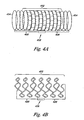
- Figure 4B illustrates another embodiment of a resonator system with a medical device according to the present disclosure.
- the system embodiment of Figure 4B includes a stent with a meandering coil 422, connecting conductors 426 and a circuit package 428.
- electrical components encapsulated by the circuit package 428 include sensors, an adjustable capacitance, an adjustable capacitance control, a processor, a memory, a power source, and a selector.
- the meandering coil of the stent 422, the connecting conductors 406, at least a portion of the adjustable capacitance, and a portion of the adjustable capacitance control together form an LC resonator circuit, with the meandering coil of the stent 422 forming the L component of the LC resonator circuit.
- the processor automatically adjusts the adjustable capacitance of the LC resonator circuit to a resonant capacitance, in response to a magnetic field strength, as described in Figures 3A and 3B .
- the system embodiment of Figure 4A can resonate over a range of MRI frequencies and stent diameters, enhancing the visualization of the stent 422, when performing MRI.
- a resonator system can be made with other implantable medical devices such as a graft, a shunt, and a vena cava filter, as will be understood by one of ordinary skill in the art.
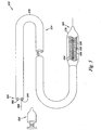
- FIG. 5 illustrates another embodiment of a resonator system with a medical device according to the present disclosure.
- the resonator system 500 of Figure 5 includes an inductor coil 504, connecting conductors 506 and a circuit package 508.
- electrical components encapsulated by the circuit package 508 include sensors, an adjustable capacitance, an adjustable capacitance control, a processor, a memory, a power source, and a selector.
- the inductor coil 504, the connecting conductors 506, a portion of the adjustable capacitance, and a portion of the adjustable capacitance control together form an LC resonator circuit.
- the processor automatically adjusts the adjustable capacitance of the LC resonator circuit to a resonant capacitance, in response to a magnetic field strength magnetic field, as described in Figures 3A and 3B .
- the system embodiment of Figure 5 can resonate over a range of MRI frequencies, enhancing the visualization of a distal end 580 of a catheter 574, when performing MRI.
- Figure 5 also illustrates the catheter 574 with an elongate body 576, an inflatable balloon 578 positioned adjacent the distal end 580, and a lumen 582 longitudinally extending in the elongate body 576 of the catheter 574 from the inflatable balloon 578 to a proximal end 584.
- the catheter 574 can further include a guidewire lumen 586 to receive a guidewire 588.
- the inflatable balloon 578 can be inflated through the use of an inflation pump 590 that can releasably couple to a lumen 582.
- the inductor coil 504 can placed inside a temporarily implantable medical device, such as the catheter 574, in various ways.
- the inductor coil 504 can be connected to a temporarily implantable medical device.
- the resonator system 500 of Figure 5 can be used with various temporarily implantable medical devices, such as a guiding catheter, a guiding wire, a catheter for stent delivery, or a catheter for dilation without a stent.
- a resonator device or system can also be implanted into a body.
- a variety of procedures can be used to implant an embodiment of a resonator device or system with an implantable medical device.
- certain embodiments of a resonator device can be implanted adjacent to a stent that has already been implanted in a body.
- both a stent and certain embodiments of a resonator device can be implanted simultaneously.
- both a stent and a resonator device could be loaded onto a catheter (e.g., a balloon catheter) for implanting in a body.
- a medical device can be a deliverable device, deliverable in a lumen of a body.
Landscapes
- Physics & Mathematics (AREA)
- Condensed Matter Physics & Semiconductors (AREA)
- General Physics & Mathematics (AREA)
- Health & Medical Sciences (AREA)
- General Health & Medical Sciences (AREA)
- Pathology (AREA)
- Magnetic Resonance Imaging Apparatus (AREA)
- External Artificial Organs (AREA)
- Prostheses (AREA)
- Surgical Instruments (AREA)
Applications Claiming Priority (2)
| Application Number | Priority Date | Filing Date | Title |
|---|---|---|---|
| US11/270,417 US7423496B2 (en) | 2005-11-09 | 2005-11-09 | Resonator with adjustable capacitance for medical device |
| PCT/US2006/041736 WO2007055914A1 (en) | 2005-11-09 | 2006-10-27 | Resonator with adjustable capacitance for medical device |
Publications (2)
| Publication Number | Publication Date |
|---|---|
| EP1946136A1 EP1946136A1 (en) | 2008-07-23 |
| EP1946136B1 true EP1946136B1 (en) | 2013-05-22 |
Family
ID=37708255
Family Applications (1)
| Application Number | Title | Priority Date | Filing Date |
|---|---|---|---|
| EP06817389.7A Not-in-force EP1946136B1 (en) | 2005-11-09 | 2006-10-27 | Resonator system for use during magnetic resonance imaging |
Country Status (5)
| Country | Link |
|---|---|
| US (2) | US7423496B2 (enExample) |
| EP (1) | EP1946136B1 (enExample) |
| JP (1) | JP5172690B2 (enExample) |
| CA (1) | CA2629054A1 (enExample) |
| WO (1) | WO2007055914A1 (enExample) |
Families Citing this family (25)
| Publication number | Priority date | Publication date | Assignee | Title |
|---|---|---|---|---|
| US7423496B2 (en) * | 2005-11-09 | 2008-09-09 | Boston Scientific Scimed, Inc. | Resonator with adjustable capacitance for medical device |
| US7933662B2 (en) | 2006-04-26 | 2011-04-26 | Marshall Mark T | Medical electrical lead including an inductance augmenter |
| US20100030319A1 (en) * | 2008-07-31 | 2010-02-04 | Boston Scientific Scimed, Inc. | Coils for vascular implants or other uses |
| US8212218B2 (en) * | 2009-11-30 | 2012-07-03 | International Business Machines Corporation | Dosimeter powered by passive RF absorption |
| KR20150042871A (ko) | 2010-09-08 | 2015-04-21 | 코비디엔 엘피 | 영상 조립체를 갖는 카테터 |
| US8612021B2 (en) | 2011-02-10 | 2013-12-17 | Medtronic, Inc. | Magnetic resonance imaging compatible medical electrical lead and method of making the same |
| US9517184B2 (en) | 2012-09-07 | 2016-12-13 | Covidien Lp | Feeding tube with insufflation device and related methods therefor |
| USD717340S1 (en) | 2012-09-07 | 2014-11-11 | Covidien Lp | Display screen with enteral feeding icon |
| US9198835B2 (en) | 2012-09-07 | 2015-12-01 | Covidien Lp | Catheter with imaging assembly with placement aid and related methods therefor |
| USD716841S1 (en) | 2012-09-07 | 2014-11-04 | Covidien Lp | Display screen with annotate file icon |
| USD735343S1 (en) | 2012-09-07 | 2015-07-28 | Covidien Lp | Console |
| EP2972442B1 (en) | 2013-03-14 | 2021-06-23 | Demir, Hilmi Volkan | Enhancement of magnetic resonance image resolution by using bio-compatible, passive resonator hardware |
| US12465324B2 (en) | 2015-02-12 | 2025-11-11 | Foundry Innovation & Research 1, Ltd. | Patient fluid management systems and methods employing integrated fluid status sensing |
| KR102358589B1 (ko) | 2015-02-12 | 2022-02-03 | 파운드리 이노베이션 앤드 리서치 1 리미티드 | 심부전 모니터링을 위한 이식가능 장치 및 관련 방법 |
| WO2017024051A1 (en) | 2015-08-03 | 2017-02-09 | Foundry Innovation & Research 1, Ltd. | Devices and methods for measurement of vena cava dimensions, pressure, and oxygen saturation |
| US11701018B2 (en) | 2016-08-11 | 2023-07-18 | Foundry Innovation & Research 1, Ltd. | Wireless resonant circuit and variable inductance vascular monitoring implants and anchoring structures therefore |
| EP3496606A1 (en) | 2016-08-11 | 2019-06-19 | Foundry Innovation & Research 1, Ltd. | Systems and methods for patient fluid management |
| US11206992B2 (en) | 2016-08-11 | 2021-12-28 | Foundry Innovation & Research 1, Ltd. | Wireless resonant circuit and variable inductance vascular monitoring implants and anchoring structures therefore |
| US9869729B1 (en) * | 2016-08-30 | 2018-01-16 | Infineon Technologies Ag | Magnetic field sensor circuit in package with means to add a signal from a coil |
| CN110300546B (zh) | 2016-11-29 | 2023-03-31 | 铸造创新&研究第一有限责任公司 | 用于监测患者脉管系统和流体状态的系统和方法 |
| US20190053760A1 (en) * | 2017-03-15 | 2019-02-21 | II Rex Ervin Gerald | Magnetic resonance imaging cancer probe and methods of use |
| US11779238B2 (en) | 2017-05-31 | 2023-10-10 | Foundry Innovation & Research 1, Ltd. | Implantable sensors for vascular monitoring |
| US11944495B2 (en) | 2017-05-31 | 2024-04-02 | Foundry Innovation & Research 1, Ltd. | Implantable ultrasonic vascular sensor |
| KR102493481B1 (ko) * | 2020-06-25 | 2023-01-31 | 아주대학교산학협력단 | 의료기기용 확장부재의 측정 시스템 및 그 방법 |
| EP4561673A1 (en) | 2022-07-29 | 2025-06-04 | Foundry Innovation & Research 1, Ltd. | Multistranded conductors adapted to dynamic in vivo environments |
Family Cites Families (143)
| Publication number | Priority date | Publication date | Assignee | Title |
|---|---|---|---|---|
| EP0114405B1 (en) | 1982-12-28 | 1987-12-02 | Kabushiki Kaisha Toshiba | Nuclear magnetic resonance diagnostic apparatus |
| JPS59122937A (ja) * | 1982-12-28 | 1984-07-16 | Toshiba Corp | 磁気共鳴イメージング装置 |
| DK149007C (da) | 1983-06-01 | 1986-07-07 | Hvidt Moebelarkitektfirma A S | Fjedersystem med variabel fjederkarakteristik |
| JPS6443241A (en) | 1987-08-10 | 1989-02-15 | Toshiba Corp | Probe coil apparatus for magnetic resonance imaging apparatus |
| JPH0236841A (ja) * | 1988-07-27 | 1990-02-06 | Toshiba Corp | 磁気共鳴イメージング装置 |
| JPH05209948A (ja) * | 1992-01-31 | 1993-08-20 | Jeol Ltd | Nmr装置等におけるプローブの自動チューニング・システム |
| US5409460A (en) * | 1993-04-15 | 1995-04-25 | The Beta Group Inc. | Intra-luminal expander assembly |
| IL124038A (en) * | 1995-10-13 | 2004-02-19 | Transvascular Inc | Apparatus for bypassing arterial obstructions and/or performing other transvascular procedures |
| US5843117A (en) | 1996-02-14 | 1998-12-01 | Inflow Dynamics Inc. | Implantable vascular and endoluminal stents and process of fabricating the same |
| US6898454B2 (en) * | 1996-04-25 | 2005-05-24 | The Johns Hopkins University | Systems and methods for evaluating the urethra and the periurethral tissues |
| US7194117B2 (en) | 1999-06-29 | 2007-03-20 | The Research Foundation Of State University Of New York | System and method for performing a three-dimensional virtual examination of objects, such as internal organs |
| US7603166B2 (en) * | 1996-09-20 | 2009-10-13 | Board Of Regents University Of Texas System | Method and apparatus for detection of vulnerable atherosclerotic plaque |
| US6099561A (en) | 1996-10-21 | 2000-08-08 | Inflow Dynamics, Inc. | Vascular and endoluminal stents with improved coatings |
| US6387121B1 (en) * | 1996-10-21 | 2002-05-14 | Inflow Dynamics Inc. | Vascular and endoluminal stents with improved coatings |
| US5824045A (en) | 1996-10-21 | 1998-10-20 | Inflow Dynamics Inc. | Vascular and endoluminal stents |
| US6106473A (en) | 1996-11-06 | 2000-08-22 | Sts Biopolymers, Inc. | Echogenic coatings |
| US5871437A (en) | 1996-12-10 | 1999-02-16 | Inflow Dynamics, Inc. | Radioactive stent for treating blood vessels to prevent restenosis |
| AU717916B2 (en) * | 1997-01-03 | 2000-04-06 | Biosense, Inc. | Pressure-sensing stent |
| US5855600A (en) * | 1997-08-01 | 1999-01-05 | Inflow Dynamics Inc. | Flexible implantable stent with composite design |
| DE19834956B9 (de) * | 1997-08-01 | 2005-10-20 | Eckhard Alt | Stützprothese (Stent) |
| DE19746735C2 (de) | 1997-10-13 | 2003-11-06 | Simag Gmbh Systeme Und Instr F | NMR-Bildgebungsverfahren zur Darstellung, Positionsbestimmung oder funktionellen Kontrolle einer in ein Untersuchungsobjekt eingeführten Vorrichtung und Vorrichtung zur Verwendung in einem derartigen Verfahren |
| US6231516B1 (en) | 1997-10-14 | 2001-05-15 | Vacusense, Inc. | Endoluminal implant with therapeutic and diagnostic capability |
| US6585763B1 (en) | 1997-10-14 | 2003-07-01 | Vascusense, Inc. | Implantable therapeutic device and method |
| US6304769B1 (en) | 1997-10-16 | 2001-10-16 | The Regents Of The University Of California | Magnetically directable remote guidance systems, and methods of use thereof |
| US6027510A (en) * | 1997-12-08 | 2000-02-22 | Inflow Dynamics Inc. | Stent delivery system |
| US6352543B1 (en) | 2000-04-29 | 2002-03-05 | Ventrica, Inc. | Methods for forming anastomoses using magnetic force |
| US7713297B2 (en) * | 1998-04-11 | 2010-05-11 | Boston Scientific Scimed, Inc. | Drug-releasing stent with ceramic-containing layer |
| US6511325B1 (en) * | 1998-05-04 | 2003-01-28 | Advanced Research & Technology Institute | Aortic stent-graft calibration and training model |
| US6463317B1 (en) | 1998-05-19 | 2002-10-08 | Regents Of The University Of Minnesota | Device and method for the endovascular treatment of aneurysms |
| GB9816012D0 (en) | 1998-07-22 | 1998-09-23 | Habib Nagy A | Treatment using implantable devices |
| US20020019660A1 (en) * | 1998-09-05 | 2002-02-14 | Marc Gianotti | Methods and apparatus for a curved stent |
| EP1115328A4 (en) * | 1998-09-24 | 2004-11-10 | Super Dimension Ltd | SYSTEM AND METHOD FOR LOCATING A CATHETER DURING AN ENDOCORPOREAL MEDICAL EXAMINATION |
| US6245104B1 (en) * | 1999-02-28 | 2001-06-12 | Inflow Dynamics Inc. | Method of fabricating a biocompatible stent |
| GB2345139A (en) * | 1998-12-24 | 2000-06-28 | Marconi Electronic Syst Ltd | MRI apparatus with continuous movement of patient |
| NL1011903C2 (nl) * | 1999-02-05 | 2000-08-08 | Surgical Innovations Vof | Verwijderbare stent. |
| US6251134B1 (en) * | 1999-02-28 | 2001-06-26 | Inflow Dynamics Inc. | Stent with high longitudinal flexibility |
| DE19921088C2 (de) | 1999-04-30 | 2003-08-07 | Magforce Applic Gmbh | Stent zur Offenhaltung gangartiger Strukturen |
| US7386339B2 (en) | 1999-05-18 | 2008-06-10 | Mediguide Ltd. | Medical imaging and navigation system |
| US7343195B2 (en) * | 1999-05-18 | 2008-03-11 | Mediguide Ltd. | Method and apparatus for real time quantitative three-dimensional image reconstruction of a moving organ and intra-body navigation |
| US6516213B1 (en) * | 1999-09-03 | 2003-02-04 | Robin Medical, Inc. | Method and apparatus to estimate location and orientation of objects during magnetic resonance imaging |
| US6802811B1 (en) | 1999-09-17 | 2004-10-12 | Endoluminal Therapeutics, Inc. | Sensing, interrogating, storing, telemetering and responding medical implants |
| JP2003510730A (ja) | 1999-09-30 | 2003-03-18 | コーニンクレッカ フィリップス エレクトロニクス エヌ ヴィ | 画像処理方法及び画像列における移動対象を追跡するシステム |
| CA2404352A1 (en) * | 2000-03-24 | 2001-10-04 | Ergin Atalar | Endoluminal mri probe |
| CA2403822A1 (en) | 2000-03-31 | 2001-10-11 | Surgi-Vision, Inc. | Systems for evaluating the urethra and the periurethral tissues |
| US6925328B2 (en) | 2000-04-20 | 2005-08-02 | Biophan Technologies, Inc. | MRI-compatible implantable device |
| AU2001255522A1 (en) | 2000-04-20 | 2001-11-07 | Greatbio Technologies, Inc. | Mri-resistant implantable device |
| AU2001286731A1 (en) * | 2000-08-25 | 2002-03-04 | Kensey Nash Corporation | Covered stents, systems for deploying covered stents |
| JP2002143156A (ja) | 2000-09-05 | 2002-05-21 | Koninkl Philips Electronics Nv | 媒体中の散乱物を撮像する超音波システム及び超音波診断装置 |
| US6716237B1 (en) * | 2000-09-18 | 2004-04-06 | Inflow Dynamics, Inc. | Interventional shielded stent delivery system and method |
| US6478815B1 (en) | 2000-09-18 | 2002-11-12 | Inflow Dynamics Inc. | Vascular and endoluminal stents |
| US7101391B2 (en) * | 2000-09-18 | 2006-09-05 | Inflow Dynamics Inc. | Primarily niobium stent |
| US7402173B2 (en) | 2000-09-18 | 2008-07-22 | Boston Scientific Scimed, Inc. | Metal stent with surface layer of noble metal oxide and method of fabrication |
| US6603081B2 (en) * | 2000-10-04 | 2003-08-05 | Mettler-Toledo Gmbh | Balance with a weighing compartment |
| WO2002031909A1 (en) * | 2000-10-11 | 2002-04-18 | Alfred E. Mann Foundation For Scientific Research | Improved antenna for miniature implanted medical device |
| US6802857B1 (en) | 2000-10-11 | 2004-10-12 | Uab Research Foundation | MRI stent |
| US6416540B1 (en) | 2000-11-01 | 2002-07-09 | Sandip V. Mathur | Magnetically actuated cleanable stent and method |
| US6787777B1 (en) | 2000-11-09 | 2004-09-07 | Koninklijke Philips Electronics, N.V. | Nuclear imaging system and method using segmented field of view |
| EP1341487B1 (en) * | 2000-12-15 | 2005-11-23 | Angiomed GmbH & Co. Medizintechnik KG | Stent with valve |
| US20020082679A1 (en) * | 2000-12-22 | 2002-06-27 | Avantec Vascular Corporation | Delivery or therapeutic capable agents |
| US6574497B1 (en) * | 2000-12-22 | 2003-06-03 | Advanced Cardiovascular Systems, Inc. | MRI medical device markers utilizing fluorine-19 |
| US6939375B2 (en) * | 2000-12-22 | 2005-09-06 | Avantac Vascular Corporation | Apparatus and methods for controlled substance delivery from implanted prostheses |
| US6767360B1 (en) | 2001-02-08 | 2004-07-27 | Inflow Dynamics Inc. | Vascular stent with composite structure for magnetic reasonance imaging capabilities |
| DE10106546A1 (de) * | 2001-02-13 | 2002-08-22 | Ethicon Gmbh | Verfahren zum Herstellen eines medizinischen Implantats |
| US20020116029A1 (en) | 2001-02-20 | 2002-08-22 | Victor Miller | MRI-compatible pacemaker with power carrying photonic catheter and isolated pulse generating electronics providing VOO functionality |
| US6829509B1 (en) | 2001-02-20 | 2004-12-07 | Biophan Technologies, Inc. | Electromagnetic interference immune tissue invasive system |
| DE10108581B4 (de) | 2001-02-22 | 2009-08-27 | Mri Devices Daum Gmbh | Material für die Kernspintomographie |
| US7371067B2 (en) | 2001-03-06 | 2008-05-13 | The Johns Hopkins University School Of Medicine | Simulation method for designing customized medical devices |
| US6786904B2 (en) | 2002-01-10 | 2004-09-07 | Triton Biosystems, Inc. | Method and device to treat vulnerable plaque |
| US6673104B2 (en) * | 2001-03-15 | 2004-01-06 | Scimed Life Systems, Inc. | Magnetic stent |
| US7771468B2 (en) * | 2001-03-16 | 2010-08-10 | Angiotech Biocoatings Corp. | Medicated stent having multi-layer polymer coating |
| US6613083B2 (en) * | 2001-05-02 | 2003-09-02 | Eckhard Alt | Stent device and method |
| US6585660B2 (en) | 2001-05-18 | 2003-07-01 | Jomed Inc. | Signal conditioning device for interfacing intravascular sensors having varying operational characteristics to a physiology monitor |
| EP1401506A4 (en) * | 2001-05-31 | 2005-02-16 | Miravant Pharm Inc | METAL TETRAPYRROLIC PHOTOSENSITIZATION AGENTS FOR PHOTODYNAMIC THERAPY |
| US6712844B2 (en) * | 2001-06-06 | 2004-03-30 | Advanced Cardiovascular Systems, Inc. | MRI compatible stent |
| DE10127850B4 (de) | 2001-06-08 | 2006-04-13 | Lars Dr.med. Grenacher | Vorrichtung zum Durchführen Kernresonanzspektroskopischer Untersuchungen im Inneren organischer Körper |
| US6585755B2 (en) * | 2001-06-29 | 2003-07-01 | Advanced Cardiovascular | Polymeric stent suitable for imaging by MRI and fluoroscopy |
| US6702847B2 (en) * | 2001-06-29 | 2004-03-09 | Scimed Life Systems, Inc. | Endoluminal device with indicator member for remote detection of endoleaks and/or changes in device morphology |
| US20030092013A1 (en) * | 2001-08-16 | 2003-05-15 | Vitivity, Inc. | Diagnosis and treatment of vascular disease |
| US6731979B2 (en) * | 2001-08-30 | 2004-05-04 | Biophan Technologies Inc. | Pulse width cardiac pacing apparatus |
| US20030096248A1 (en) * | 2001-09-04 | 2003-05-22 | Vitivity, Inc. | Diagnosis and treatment of vascular disease |
| US20030187335A1 (en) | 2001-09-26 | 2003-10-02 | Vitivity, Inc. | Diagnosis and treatment of vascular disease |
| US20030099957A1 (en) * | 2001-09-28 | 2003-05-29 | Vitivity, Inc. | Diagnosis and treatment of vascular disease |
| US20030087244A1 (en) * | 2001-10-09 | 2003-05-08 | Vitivity, Inc | Diagnosis and treatment of vascular disease |
| US6884234B2 (en) * | 2001-11-01 | 2005-04-26 | Cardio Exodus Partners | Foldable and remotely imageable balloon |
| US7587234B2 (en) * | 2001-11-02 | 2009-09-08 | Abbott Cardiovascular Systems Inc. | Method and apparatus for computer modified magnetic resonance imaging |
| US6782284B1 (en) | 2001-11-21 | 2004-08-24 | Koninklijke Philips Electronics, N.V. | Method and apparatus for semi-automatic aneurysm measurement and stent planning using volume image data |
| US6785572B2 (en) | 2001-11-21 | 2004-08-31 | Koninklijke Philips Electronics, N.V. | Tactile feedback and display in a CT image guided robotic system for interventional procedures |
| US20040143180A1 (en) | 2001-11-27 | 2004-07-22 | Sheng-Ping Zhong | Medical devices visible under magnetic resonance imaging |
| US20030100830A1 (en) * | 2001-11-27 | 2003-05-29 | Sheng-Ping Zhong | Implantable or insertable medical devices visible under magnetic resonance imaging |
| US20030143544A1 (en) | 2002-01-09 | 2003-07-31 | Vitivity, Inc. | Diagnosis and treatment of vascular disease |
| US7048756B2 (en) * | 2002-01-18 | 2006-05-23 | Apasara Medical Corporation | System, method and apparatus for evaluating tissue temperature |
| US6850804B2 (en) * | 2002-01-18 | 2005-02-01 | Calfacior Corporation | System method and apparatus for localized heating of tissue |
| WO2003061755A2 (en) | 2002-01-22 | 2003-07-31 | Nanoset, Llc | Nanomagnetically shielded substrate |
| US7162302B2 (en) | 2002-03-04 | 2007-01-09 | Nanoset Llc | Magnetically shielded assembly |
| US20040210289A1 (en) | 2002-03-04 | 2004-10-21 | Xingwu Wang | Novel nanomagnetic particles |
| US7091412B2 (en) | 2002-03-04 | 2006-08-15 | Nanoset, Llc | Magnetically shielded assembly |
| US6844492B1 (en) * | 2002-01-22 | 2005-01-18 | Nanoset, Llc | Magnetically shielded conductor |
| US20050178584A1 (en) | 2002-01-22 | 2005-08-18 | Xingwu Wang | Coated stent and MR imaging thereof |
| US6663570B2 (en) * | 2002-02-27 | 2003-12-16 | Volcano Therapeutics, Inc. | Connector for interfacing intravascular sensors to a physiology monitor |
| US20040038303A1 (en) * | 2002-04-08 | 2004-02-26 | Unger Gretchen M. | Biologic modulations with nanoparticles |
| US6711440B2 (en) * | 2002-04-11 | 2004-03-23 | Biophan Technologies, Inc. | MRI-compatible medical device with passive generation of optical sensing signals |
| US20030199747A1 (en) | 2002-04-19 | 2003-10-23 | Michlitsch Kenneth J. | Methods and apparatus for the identification and stabilization of vulnerable plaque |
| US6725092B2 (en) * | 2002-04-25 | 2004-04-20 | Biophan Technologies, Inc. | Electromagnetic radiation immune medical assist device adapter |
| AU2003228858A1 (en) * | 2002-05-02 | 2003-11-17 | Scimed Life Systems, Inc. | Energetically-controlled delivery of biologically active material from an implanted medical device |
| US7189256B2 (en) | 2002-05-10 | 2007-03-13 | Scimed Life Systems, Inc. | Endoluminal device and system and method for detecting a change in pressure differential across an endoluminal device |
| US6676694B1 (en) * | 2002-06-06 | 2004-01-13 | Mitchell Weiss | Method for installing a stent graft |
| US6957098B1 (en) | 2002-06-27 | 2005-10-18 | Advanced Cardiovascular Systems, Inc. | Markers for interventional devices in magnetic resonant image (MRI) systems |
| US7343659B2 (en) * | 2002-07-10 | 2008-03-18 | Boston Scientific Scimed, Inc. | Method of making a medical device |
| US6925322B2 (en) | 2002-07-25 | 2005-08-02 | Biophan Technologies, Inc. | Optical MRI catheter system |
| US6892090B2 (en) | 2002-08-19 | 2005-05-10 | Surgical Navigation Technologies, Inc. | Method and apparatus for virtual endoscopy |
| US7029495B2 (en) * | 2002-08-28 | 2006-04-18 | Scimed Life Systems, Inc. | Medical devices and methods of making the same |
| US6575566B1 (en) * | 2002-09-18 | 2003-06-10 | Eastman Kodak Company | Continuous inkjet printhead with selectable printing volumes of ink |
| US20040116997A1 (en) * | 2002-09-20 | 2004-06-17 | Taylor Charles S. | Stent-graft with positioning anchor |
| US7881769B2 (en) * | 2002-11-18 | 2011-02-01 | Mediguide Ltd. | Method and system for mounting an MPS sensor on a catheter |
| US7697972B2 (en) * | 2002-11-19 | 2010-04-13 | Medtronic Navigation, Inc. | Navigation system for cardiac therapies |
| US7172624B2 (en) | 2003-02-06 | 2007-02-06 | Boston Scientific Scimed, Inc. | Medical device with magnetic resonance visibility enhancing structure |
| US7792568B2 (en) | 2003-03-17 | 2010-09-07 | Boston Scientific Scimed, Inc. | MRI-visible medical devices |
| US20040199069A1 (en) * | 2003-04-02 | 2004-10-07 | Connelly Patrick R. | Device and method for preventing magnetic resonance imaging induced damage |
| US20050107870A1 (en) * | 2003-04-08 | 2005-05-19 | Xingwu Wang | Medical device with multiple coating layers |
| US20050216075A1 (en) | 2003-04-08 | 2005-09-29 | Xingwu Wang | Materials and devices of enhanced electromagnetic transparency |
| US20050079132A1 (en) * | 2003-04-08 | 2005-04-14 | Xingwu Wang | Medical device with low magnetic susceptibility |
| US20050025797A1 (en) * | 2003-04-08 | 2005-02-03 | Xingwu Wang | Medical device with low magnetic susceptibility |
| US20050149002A1 (en) | 2003-04-08 | 2005-07-07 | Xingwu Wang | Markers for visualizing interventional medical devices |
| US20050165471A1 (en) | 2003-04-08 | 2005-07-28 | Xingwu Wang | Implantable medical device |
| US20050155779A1 (en) | 2003-04-08 | 2005-07-21 | Xingwu Wang | Coated substrate assembly |
| US20050149169A1 (en) | 2003-04-08 | 2005-07-07 | Xingwu Wang | Implantable medical device |
| US20040254419A1 (en) | 2003-04-08 | 2004-12-16 | Xingwu Wang | Therapeutic assembly |
| US8021418B2 (en) * | 2003-06-19 | 2011-09-20 | Boston Scientific Scimed, Inc. | Sandwiched radiopaque marker on covered stent |
| AR047692A1 (es) * | 2003-07-10 | 2006-02-08 | Epix Medical Inc | Imagenes de blancos estacionarios |
| US7479157B2 (en) * | 2003-08-07 | 2009-01-20 | Boston Scientific Scimed, Inc. | Stent designs which enable the visibility of the inside of the stent during MRI |
| US7344559B2 (en) * | 2003-08-25 | 2008-03-18 | Biophan Technologies, Inc. | Electromagnetic radiation transparent device and method of making thereof |
| US20050065437A1 (en) * | 2003-09-24 | 2005-03-24 | Scimed Life Systems, Inc. | Medical device with markers for magnetic resonance visibility |
| US7186209B2 (en) * | 2003-10-09 | 2007-03-06 | Jacobson Jerry I | Cardioelectromagnetic treatment |
| US20050085895A1 (en) * | 2003-10-15 | 2005-04-21 | Scimed Life Systems, Inc. | RF-based markers for MRI visualization of medical devices |
| WO2005051444A2 (en) | 2003-11-20 | 2005-06-09 | Angiotech International Ag | Soft tissue implants and anti-scarring agents |
| US20050209664A1 (en) | 2003-11-20 | 2005-09-22 | Angiotech International Ag | Electrical devices and anti-scarring agents |
| US20050208095A1 (en) | 2003-11-20 | 2005-09-22 | Angiotech International Ag | Polymer compositions and methods for their use |
| US20050131522A1 (en) * | 2003-12-10 | 2005-06-16 | Stinson Jonathan S. | Medical devices and methods of making the same |
| US7632299B2 (en) | 2004-01-22 | 2009-12-15 | Boston Scientific Scimed, Inc. | Medical devices |
| US7020517B2 (en) | 2004-02-20 | 2006-03-28 | Biophan Technologies, Inc. | Fibrillation/tachycardia monitoring and preventive system and methodology |
| US20050215764A1 (en) | 2004-03-24 | 2005-09-29 | Tuszynski Jack A | Biological polymer with differently charged portions |
| US7239918B2 (en) * | 2004-06-10 | 2007-07-03 | Ndi Medical Inc. | Implantable pulse generator for providing functional and/or therapeutic stimulation of muscles and/or nerves and/or central nervous system tissue |
| US7423496B2 (en) * | 2005-11-09 | 2008-09-09 | Boston Scientific Scimed, Inc. | Resonator with adjustable capacitance for medical device |
-
2005
- 2005-11-09 US US11/270,417 patent/US7423496B2/en not_active Expired - Fee Related
-
2006
- 2006-10-27 JP JP2008540043A patent/JP5172690B2/ja not_active Expired - Fee Related
- 2006-10-27 CA CA002629054A patent/CA2629054A1/en not_active Abandoned
- 2006-10-27 WO PCT/US2006/041736 patent/WO2007055914A1/en not_active Ceased
- 2006-10-27 EP EP06817389.7A patent/EP1946136B1/en not_active Not-in-force
-
2008
- 2008-07-29 US US12/220,819 patent/US8046048B2/en not_active Expired - Fee Related
Also Published As
| Publication number | Publication date |
|---|---|
| CA2629054A1 (en) | 2007-05-18 |
| JP2009514639A (ja) | 2009-04-09 |
| US20070106151A1 (en) | 2007-05-10 |
| US8046048B2 (en) | 2011-10-25 |
| WO2007055914A1 (en) | 2007-05-18 |
| EP1946136A1 (en) | 2008-07-23 |
| US7423496B2 (en) | 2008-09-09 |
| JP5172690B2 (ja) | 2013-03-27 |
| US20080290958A1 (en) | 2008-11-27 |
Similar Documents
| Publication | Publication Date | Title |
|---|---|---|
| US8046048B2 (en) | Resonator with adjustable capacitance for medical device | |
| US7205768B2 (en) | Connection lead for an electrical accessory device of an MRI system | |
| US10976388B2 (en) | Minimizing intravascular magnetic resonance imaging (MRI) guidewire heating with single layer MRI transmit/receive radio frequency coil | |
| US8237442B2 (en) | Magnetic resonance antenna | |
| US8116846B2 (en) | Intravascular antenna | |
| EP2618171A1 (en) | Multi-resonant T/R antenna for MR image generation | |
| US11156682B2 (en) | Single layer magnetic resonance imaging transmit/receive radio frequency coil for different anatomies | |
| EP2054733A1 (en) | Tunable and/or detunable mr receive coil arrangements | |
| WO2004015438A1 (en) | Mri enhancing intravascular device with trimmable capacitor | |
| CN102414571B (zh) | 用于多共振的磁共振系统中的设备和布线 | |
| US20230261375A1 (en) | Transmission line coupled antenna and detuning circuit | |
| US20120232632A1 (en) | medical implantable lead | |
| CN210864013U (zh) | 磁共振天线 |
Legal Events
| Date | Code | Title | Description |
|---|---|---|---|
| PUAI | Public reference made under article 153(3) epc to a published international application that has entered the european phase |
Free format text: ORIGINAL CODE: 0009012 |
|
| 17P | Request for examination filed |
Effective date: 20080509 |
|
| AK | Designated contracting states |
Kind code of ref document: A1 Designated state(s): AT BE BG CH CY CZ DE DK EE ES FI FR GB GR HU IE IS IT LI LT LU LV MC NL PL PT RO SE SI SK TR |
|
| 17Q | First examination report despatched |
Effective date: 20110218 |
|
| DAX | Request for extension of the european patent (deleted) | ||
| GRAP | Despatch of communication of intention to grant a patent |
Free format text: ORIGINAL CODE: EPIDOSNIGR1 |
|
| GRAS | Grant fee paid |
Free format text: ORIGINAL CODE: EPIDOSNIGR3 |
|
| GRAA | (expected) grant |
Free format text: ORIGINAL CODE: 0009210 |
|
| AK | Designated contracting states |
Kind code of ref document: B1 Designated state(s): AT BE BG CH CY CZ DE DK EE ES FI FR GB GR HU IE IS IT LI LT LU LV MC NL PL PT RO SE SI SK TR |
|
| REG | Reference to a national code |
Ref country code: GB Ref legal event code: FG4D |
|
| REG | Reference to a national code |
Ref country code: CH Ref legal event code: EP |
|
| REG | Reference to a national code |
Ref country code: AT Ref legal event code: REF Ref document number: 613496 Country of ref document: AT Kind code of ref document: T Effective date: 20130615 |
|
| REG | Reference to a national code |
Ref country code: IE Ref legal event code: FG4D |
|
| REG | Reference to a national code |
Ref country code: DE Ref legal event code: R096 Ref document number: 602006036484 Country of ref document: DE Effective date: 20130718 |
|
| REG | Reference to a national code |
Ref country code: AT Ref legal event code: MK05 Ref document number: 613496 Country of ref document: AT Kind code of ref document: T Effective date: 20130522 |
|
| REG | Reference to a national code |
Ref country code: LT Ref legal event code: MG4D |
|
| PG25 | Lapsed in a contracting state [announced via postgrant information from national office to epo] |
Ref country code: LT Free format text: LAPSE BECAUSE OF FAILURE TO SUBMIT A TRANSLATION OF THE DESCRIPTION OR TO PAY THE FEE WITHIN THE PRESCRIBED TIME-LIMIT Effective date: 20130522 Ref country code: ES Free format text: LAPSE BECAUSE OF FAILURE TO SUBMIT A TRANSLATION OF THE DESCRIPTION OR TO PAY THE FEE WITHIN THE PRESCRIBED TIME-LIMIT Effective date: 20130902 Ref country code: FI Free format text: LAPSE BECAUSE OF FAILURE TO SUBMIT A TRANSLATION OF THE DESCRIPTION OR TO PAY THE FEE WITHIN THE PRESCRIBED TIME-LIMIT Effective date: 20130522 Ref country code: SE Free format text: LAPSE BECAUSE OF FAILURE TO SUBMIT A TRANSLATION OF THE DESCRIPTION OR TO PAY THE FEE WITHIN THE PRESCRIBED TIME-LIMIT Effective date: 20130522 Ref country code: GR Free format text: LAPSE BECAUSE OF FAILURE TO SUBMIT A TRANSLATION OF THE DESCRIPTION OR TO PAY THE FEE WITHIN THE PRESCRIBED TIME-LIMIT Effective date: 20130823 Ref country code: AT Free format text: LAPSE BECAUSE OF FAILURE TO SUBMIT A TRANSLATION OF THE DESCRIPTION OR TO PAY THE FEE WITHIN THE PRESCRIBED TIME-LIMIT Effective date: 20130522 Ref country code: SI Free format text: LAPSE BECAUSE OF FAILURE TO SUBMIT A TRANSLATION OF THE DESCRIPTION OR TO PAY THE FEE WITHIN THE PRESCRIBED TIME-LIMIT Effective date: 20130522 Ref country code: PT Free format text: LAPSE BECAUSE OF FAILURE TO SUBMIT A TRANSLATION OF THE DESCRIPTION OR TO PAY THE FEE WITHIN THE PRESCRIBED TIME-LIMIT Effective date: 20130923 Ref country code: IS Free format text: LAPSE BECAUSE OF FAILURE TO SUBMIT A TRANSLATION OF THE DESCRIPTION OR TO PAY THE FEE WITHIN THE PRESCRIBED TIME-LIMIT Effective date: 20130922 |
|
| REG | Reference to a national code |
Ref country code: NL Ref legal event code: VDEP Effective date: 20130522 |
|
| PG25 | Lapsed in a contracting state [announced via postgrant information from national office to epo] |
Ref country code: PL Free format text: LAPSE BECAUSE OF FAILURE TO SUBMIT A TRANSLATION OF THE DESCRIPTION OR TO PAY THE FEE WITHIN THE PRESCRIBED TIME-LIMIT Effective date: 20130522 Ref country code: BG Free format text: LAPSE BECAUSE OF FAILURE TO SUBMIT A TRANSLATION OF THE DESCRIPTION OR TO PAY THE FEE WITHIN THE PRESCRIBED TIME-LIMIT Effective date: 20130822 |
|
| PG25 | Lapsed in a contracting state [announced via postgrant information from national office to epo] |
Ref country code: LV Free format text: LAPSE BECAUSE OF FAILURE TO SUBMIT A TRANSLATION OF THE DESCRIPTION OR TO PAY THE FEE WITHIN THE PRESCRIBED TIME-LIMIT Effective date: 20130522 |
|
| PG25 | Lapsed in a contracting state [announced via postgrant information from national office to epo] |
Ref country code: CZ Free format text: LAPSE BECAUSE OF FAILURE TO SUBMIT A TRANSLATION OF THE DESCRIPTION OR TO PAY THE FEE WITHIN THE PRESCRIBED TIME-LIMIT Effective date: 20130522 Ref country code: SK Free format text: LAPSE BECAUSE OF FAILURE TO SUBMIT A TRANSLATION OF THE DESCRIPTION OR TO PAY THE FEE WITHIN THE PRESCRIBED TIME-LIMIT Effective date: 20130522 Ref country code: BE Free format text: LAPSE BECAUSE OF FAILURE TO SUBMIT A TRANSLATION OF THE DESCRIPTION OR TO PAY THE FEE WITHIN THE PRESCRIBED TIME-LIMIT Effective date: 20130522 Ref country code: DK Free format text: LAPSE BECAUSE OF FAILURE TO SUBMIT A TRANSLATION OF THE DESCRIPTION OR TO PAY THE FEE WITHIN THE PRESCRIBED TIME-LIMIT Effective date: 20130522 Ref country code: EE Free format text: LAPSE BECAUSE OF FAILURE TO SUBMIT A TRANSLATION OF THE DESCRIPTION OR TO PAY THE FEE WITHIN THE PRESCRIBED TIME-LIMIT Effective date: 20130522 |
|
| PGFP | Annual fee paid to national office [announced via postgrant information from national office to epo] |
Ref country code: IE Payment date: 20131010 Year of fee payment: 8 Ref country code: DE Payment date: 20131023 Year of fee payment: 8 |
|
| PG25 | Lapsed in a contracting state [announced via postgrant information from national office to epo] |
Ref country code: IT Free format text: LAPSE BECAUSE OF FAILURE TO SUBMIT A TRANSLATION OF THE DESCRIPTION OR TO PAY THE FEE WITHIN THE PRESCRIBED TIME-LIMIT Effective date: 20130522 Ref country code: RO Free format text: LAPSE BECAUSE OF FAILURE TO SUBMIT A TRANSLATION OF THE DESCRIPTION OR TO PAY THE FEE WITHIN THE PRESCRIBED TIME-LIMIT Effective date: 20130522 Ref country code: NL Free format text: LAPSE BECAUSE OF FAILURE TO SUBMIT A TRANSLATION OF THE DESCRIPTION OR TO PAY THE FEE WITHIN THE PRESCRIBED TIME-LIMIT Effective date: 20130522 |
|
| PLBE | No opposition filed within time limit |
Free format text: ORIGINAL CODE: 0009261 |
|
| STAA | Information on the status of an ep patent application or granted ep patent |
Free format text: STATUS: NO OPPOSITION FILED WITHIN TIME LIMIT |
|
| 26N | No opposition filed |
Effective date: 20140225 |
|
| PG25 | Lapsed in a contracting state [announced via postgrant information from national office to epo] |
Ref country code: MC Free format text: LAPSE BECAUSE OF FAILURE TO SUBMIT A TRANSLATION OF THE DESCRIPTION OR TO PAY THE FEE WITHIN THE PRESCRIBED TIME-LIMIT Effective date: 20130522 |
|
| REG | Reference to a national code |
Ref country code: CH Ref legal event code: PL |
|
| REG | Reference to a national code |
Ref country code: DE Ref legal event code: R097 Ref document number: 602006036484 Country of ref document: DE Effective date: 20140225 |
|
| GBPC | Gb: european patent ceased through non-payment of renewal fee |
Effective date: 20131027 |
|
| PG25 | Lapsed in a contracting state [announced via postgrant information from national office to epo] |
Ref country code: GB Free format text: LAPSE BECAUSE OF NON-PAYMENT OF DUE FEES Effective date: 20131027 Ref country code: LI Free format text: LAPSE BECAUSE OF NON-PAYMENT OF DUE FEES Effective date: 20131031 Ref country code: CH Free format text: LAPSE BECAUSE OF NON-PAYMENT OF DUE FEES Effective date: 20131031 |
|
| REG | Reference to a national code |
Ref country code: FR Ref legal event code: ST Effective date: 20140630 |
|
| PG25 | Lapsed in a contracting state [announced via postgrant information from national office to epo] |
Ref country code: FR Free format text: LAPSE BECAUSE OF NON-PAYMENT OF DUE FEES Effective date: 20131031 |
|
| REG | Reference to a national code |
Ref country code: DE Ref legal event code: R082 Ref document number: 602006036484 Country of ref document: DE Representative=s name: FISH & RICHARDSON P.C., DE |
|
| REG | Reference to a national code |
Ref country code: DE Ref legal event code: R082 Ref document number: 602006036484 Country of ref document: DE Representative=s name: FISH & RICHARDSON P.C., DE Effective date: 20150202 Ref country code: DE Ref legal event code: R081 Ref document number: 602006036484 Country of ref document: DE Owner name: BOSTON SCIENTIFIC LIMITED, BM Free format text: FORMER OWNER: BOSTON SCIENTIFIC LTD., ST. MICHAEL, BARBADOS, BB Effective date: 20150202 |
|
| REG | Reference to a national code |
Ref country code: DE Ref legal event code: R119 Ref document number: 602006036484 Country of ref document: DE |
|
| PG25 | Lapsed in a contracting state [announced via postgrant information from national office to epo] |
Ref country code: TR Free format text: LAPSE BECAUSE OF FAILURE TO SUBMIT A TRANSLATION OF THE DESCRIPTION OR TO PAY THE FEE WITHIN THE PRESCRIBED TIME-LIMIT Effective date: 20130522 Ref country code: CY Free format text: LAPSE BECAUSE OF FAILURE TO SUBMIT A TRANSLATION OF THE DESCRIPTION OR TO PAY THE FEE WITHIN THE PRESCRIBED TIME-LIMIT Effective date: 20130522 |
|
| REG | Reference to a national code |
Ref country code: IE Ref legal event code: MM4A |
|
| PG25 | Lapsed in a contracting state [announced via postgrant information from national office to epo] |
Ref country code: DE Free format text: LAPSE BECAUSE OF NON-PAYMENT OF DUE FEES Effective date: 20150501 Ref country code: HU Free format text: LAPSE BECAUSE OF FAILURE TO SUBMIT A TRANSLATION OF THE DESCRIPTION OR TO PAY THE FEE WITHIN THE PRESCRIBED TIME-LIMIT; INVALID AB INITIO Effective date: 20061027 Ref country code: LU Free format text: LAPSE BECAUSE OF NON-PAYMENT OF DUE FEES Effective date: 20131027 |
|
| PG25 | Lapsed in a contracting state [announced via postgrant information from national office to epo] |
Ref country code: IE Free format text: LAPSE BECAUSE OF NON-PAYMENT OF DUE FEES Effective date: 20141027 |