EP1945549B1 - Method and system for feeding a continuous rod of elastomeric material automatically to a user unit - Google Patents
Method and system for feeding a continuous rod of elastomeric material automatically to a user unit Download PDFInfo
- Publication number
- EP1945549B1 EP1945549B1 EP06807426A EP06807426A EP1945549B1 EP 1945549 B1 EP1945549 B1 EP 1945549B1 EP 06807426 A EP06807426 A EP 06807426A EP 06807426 A EP06807426 A EP 06807426A EP 1945549 B1 EP1945549 B1 EP 1945549B1
- Authority
- EP
- European Patent Office
- Prior art keywords
- rod
- movable
- rollers
- path
- supporting device
- Prior art date
- Legal status (The legal status is an assumption and is not a legal conclusion. Google has not performed a legal analysis and makes no representation as to the accuracy of the status listed.)
- Not-in-force
Links
- 239000013536 elastomeric material Substances 0.000 title claims abstract description 14
- 238000000034 method Methods 0.000 title claims abstract description 13
- 238000011144 upstream manufacturing Methods 0.000 claims abstract description 4
- 230000005484 gravity Effects 0.000 claims 1
- 230000000717 retained effect Effects 0.000 claims 1
- 238000005303 weighing Methods 0.000 claims 1
- 238000010073 coating (rubber) Methods 0.000 description 3
- 239000011248 coating agent Substances 0.000 description 1
- 238000000576 coating method Methods 0.000 description 1
- 238000004519 manufacturing process Methods 0.000 description 1
- 230000001131 transforming effect Effects 0.000 description 1
Images

Classifications
-
- B—PERFORMING OPERATIONS; TRANSPORTING
- B29—WORKING OF PLASTICS; WORKING OF SUBSTANCES IN A PLASTIC STATE IN GENERAL
- B29D—PRODUCING PARTICULAR ARTICLES FROM PLASTICS OR FROM SUBSTANCES IN A PLASTIC STATE
- B29D30/00—Producing pneumatic or solid tyres or parts thereof
- B29D30/06—Pneumatic tyres or parts thereof (e.g. produced by casting, moulding, compression moulding, injection moulding, centrifugal casting)
- B29D30/08—Building tyres
- B29D30/10—Building tyres on round cores, i.e. the shape of the core is approximately identical with the shape of the completed tyre
- B29D30/16—Applying the layers; Guiding or stretching the layers during application
- B29D30/1628—Applying the layers; Guiding or stretching the layers during application by feeding a continuous band and winding it helically, i.e. the band is fed while being advanced along the core axis, to form an annular element
-
- B—PERFORMING OPERATIONS; TRANSPORTING
- B29—WORKING OF PLASTICS; WORKING OF SUBSTANCES IN A PLASTIC STATE IN GENERAL
- B29D—PRODUCING PARTICULAR ARTICLES FROM PLASTICS OR FROM SUBSTANCES IN A PLASTIC STATE
- B29D30/00—Producing pneumatic or solid tyres or parts thereof
- B29D30/06—Pneumatic tyres or parts thereof (e.g. produced by casting, moulding, compression moulding, injection moulding, centrifugal casting)
- B29D30/08—Building tyres
- B29D30/10—Building tyres on round cores, i.e. the shape of the core is approximately identical with the shape of the completed tyre
- B29D30/16—Applying the layers; Guiding or stretching the layers during application
- B29D30/1635—Applying the layers; Guiding or stretching the layers during application by feeding a continuous band and moving it back and forth (zig-zag) to form an annular element
-
- B—PERFORMING OPERATIONS; TRANSPORTING
- B29—WORKING OF PLASTICS; WORKING OF SUBSTANCES IN A PLASTIC STATE IN GENERAL
- B29D—PRODUCING PARTICULAR ARTICLES FROM PLASTICS OR FROM SUBSTANCES IN A PLASTIC STATE
- B29D30/00—Producing pneumatic or solid tyres or parts thereof
- B29D30/06—Pneumatic tyres or parts thereof (e.g. produced by casting, moulding, compression moulding, injection moulding, centrifugal casting)
- B29D30/08—Building tyres
- B29D30/20—Building tyres by the flat-tyre method, i.e. building on cylindrical drums
- B29D30/30—Applying the layers; Guiding or stretching the layers during application
- B29D30/3028—Applying the layers; Guiding or stretching the layers during application by feeding a continuous band and winding it helically, i.e. the band is fed while being advanced along the drum axis, to form an annular element
-
- B—PERFORMING OPERATIONS; TRANSPORTING
- B29—WORKING OF PLASTICS; WORKING OF SUBSTANCES IN A PLASTIC STATE IN GENERAL
- B29D—PRODUCING PARTICULAR ARTICLES FROM PLASTICS OR FROM SUBSTANCES IN A PLASTIC STATE
- B29D30/00—Producing pneumatic or solid tyres or parts thereof
- B29D30/06—Pneumatic tyres or parts thereof (e.g. produced by casting, moulding, compression moulding, injection moulding, centrifugal casting)
- B29D30/08—Building tyres
- B29D30/20—Building tyres by the flat-tyre method, i.e. building on cylindrical drums
- B29D30/30—Applying the layers; Guiding or stretching the layers during application
- B29D30/3035—Applying the layers; Guiding or stretching the layers during application by feeding a continuous band and moving it back and forth (zig-zag) to form an annular element
-
- B—PERFORMING OPERATIONS; TRANSPORTING
- B65—CONVEYING; PACKING; STORING; HANDLING THIN OR FILAMENTARY MATERIAL
- B65H—HANDLING THIN OR FILAMENTARY MATERIAL, e.g. SHEETS, WEBS, CABLES
- B65H51/00—Forwarding filamentary material
- B65H51/20—Devices for temporarily storing filamentary material during forwarding, e.g. for buffer storage
-
- B—PERFORMING OPERATIONS; TRANSPORTING
- B65—CONVEYING; PACKING; STORING; HANDLING THIN OR FILAMENTARY MATERIAL
- B65H—HANDLING THIN OR FILAMENTARY MATERIAL, e.g. SHEETS, WEBS, CABLES
- B65H2801/00—Application field
- B65H2801/93—Tyres
Definitions
- the present invention relates to a method and system for feeding a continuous rod of elastomeric material automatically to a user unit, preferably, though not necessarily, a unit for rubber-coating an annular surface of a toroidal body forming part of a tyre, to which the following description refers purely by way of example.
- an annular surface of a toroidal body is known to be rubber-coated using a rubber-coating system, which coats the annular surface gradually with a strip of elastomeric material of given cross section.
- the toroidal body is mounted on a spindle, is rotated about its axis by a motor, and defines, with the spindle, a user unit of said strip.
- the strip is normally fed to the annular surface, and hence to the user unit, by a feed unit comprising an extruder for producing elastomeric material in the form of a normally circuiar-section rod; an applicator roller tangent to the annular surface; and a feed line for feeding the elastomeric material from the extruder to the applicator roller.
- the feed line normally comprises a number of powered components arranged in series, and one of which is preferably, though not necessarily, a calender for transforming the rod produced by the extruder into said strip of given cross section.
- Each of the powered components is normally preceded, along the feed line, by a take-up unit designed to compensate for any difference in travelling speed between the powered component and either the part of the feed line or the extruder preceding the powered component, and to regulate the various travelling speeds to achieve a substantially constant mean travelling speed of the rod produced by the extruder.
- known take-up units normally comprise a take-up device, which is supported, in use, by the rod at a bend of varying length, and is movable, alongside variations in the length of the bend, within a range defined by two control sensors located one over the other and a given distance apart.
- take-up units are known, for example from DE 20 2004 009247 , which allow automatic feeding of a rod like element
- a method of feeding a continuous rod of elastomeric material automatically to a user unit as claimed in Claim 1 and preferably in any one of the following Claims depending directly or indirectly on Claim 1.
- a system for feeding a continuous rod of elastomeric material automatically to a user unit as claimed in Claim 8 and preferably in any one of the following Claims depending directly or indirectly on Claim 8.
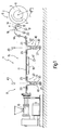
- Number 1 in Figure 1 indicates as a whole a system for rubber-coating an annular surface 2 of a toroidal body 3 forming part of a tyre (not shown).
- Annular surface 2 is rubber-coated by coating it gradually with a strip 4 of elastomeric material of given cross section.
- toroidal body 3 is mounted on a spindle 5, is rotated about its axis 6, coaxial with annular surface 2, by a variable-speed motor 7, and defines, together with spindle 5, a user unit 8 of strip 4.
- Strip 4 is fed to annular surface 2 by a feed unit 9 forming part of system 1 and comprising a screw extruder 10 for producing elastomeric material in the form of a normally circular-section rod 11; and an applicator roller 12 tangent, in use, to annular surface 2 and rotated about an axis 14 by a drive unit 13.
- applicator roller 12 is idle, and spindle 5 substitutes for drive unit 13, which is eliminated.
- System 1 also comprises a feed line 15 for feeding the elastomeric material from extruder 10 to applicator roller 12.
- feed line 15 comprises a powered belt conveyor 16 for receiving rod 11 and powered by a drive unit 17; and a calender 18, which receives and transforms rod 11 into strip 4, is interposed between an output of belt conveyor 16 and applicator roller 12, has an input guide 19, and is powered by a drive unit 20.
- conveyor 16 and calender 18 - are each preceded by a respective take-up unit 21 for compensating any difference in the travelling speed of rod 11 up- and downstream from take-up unit 21.
- one of the two take-up units 21 controls the speed of the screw (not shown) of extruder 10, and the other controls drive unit 17 of conveyor 16.
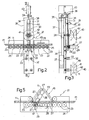
- each take-up unit 21 comprises a conveyor 22 having two end portions, each defined by a number of rollers 23 which may be idle or powered in known manner, and are fitted to a frame 24 to rotate about respective fixed, substantially horizontal axes 25, parallel to and coplanar with one another, to feed strip 11 in a direction 26 crosswise to axes 25.
- Conveyor 22 also has a central portion defined by a number of rollers 27, which may be idle or powered in known manner, and are fitted to a substantially horizontal cross member 28 parallel to direction 26. Rollers 27 rotate about respective axes 29, which are fixed with respect to cross member 28, are equally spaced along cross member 28, and are coplanar with one another and parallel to axes 25.
- cross member 28 forms part of a slide 30, which also comprises a substantially vertical shaft 31 fitted with cross member 28 close to its bottom end, and mounted to slide along a guide 32 defined by two numbers of idle guide rollers 33 parallel to rollers 23 and 27 and projecting from a front wall 34 of an upright 35.
- Upright 35 is integral with frame 24, and has, behind front wall 34, a slide channel 36 for a counterweight 37, which is connected to the top end of shaft 31 by a cable 38 wound about two guide pulleys 39 fitted to the top of upright 35, and one of which may be powered.
- shaft 31 is fitted with a take-up device 40 forming part of slide 30 and comprising a pulley 41 facing rollers 27 and fitted to shaft 31 to rotate about an axis 42 parallel to axes 25 and 29.
- a sensor 43 is fitted to the top of upright 35 and aimed at a target 44, fitted to shaft 31, to determine the position of slide 30 along guide 32.
- Counterweight 37 is adjustable so that it weighs a given amount less than slide 30, and can be locked, by a known automatic brake (not shown), into a lowered rest position (shown by the continuous line in Figure 3 ), in which rollers 27 are maintained by cable 38 in a rest position coplanar with rollers 23.
- a known automatic brake not shown
- counterweight 37 rises, by virtue of the difference in weight between counterweight 37 and slide 30, and the slide, in particular cross member 28, falls so that rollers 27 are no longer coplanar with rollers 23, thus forming, along conveyor 22 ( Figure 4 ), a window 45 centred with respect to guide 32 and wide enough to permit passage of take-up device 40.
- each path P1 is substantially horizontal (but may slope in any direction, e.g. downwards), is substantially straight (but may be curved), extends in direction 26, and in any case is of a respective given fixed length.
- extruder 10 produces a rod 11, which is pushed onto conveyor 22 of the first take-up unit 21, and proceeds in direction 26, along relative path P1 tangent to relative coplanar rollers 23 and 27, up to belt conveyor 16.
- rod 11 passes beneath take-up device 40 of the first take-up unit 21, seeing as relative pulley 41, when relative slide 30 is in the rest position, is located over relative path P1 and on the opposite side of relative path P1 to relative rollers 23 and 27.
- Rod 11 is fed by belt conveyor 16 to the second take-up unit 21, travels through it in the same way as described for the first take-up unit 21, and is fed to applicator roller 12 and then to surface 2 of toroidal body 3 via calender 18 and relative input guide 19.
- each take-up device 40 may be released once rod 11 firmly engages the next powered component.
- cross member 28 is rotated downwards in opposition to a brake member, e.g. a counterweight.
Landscapes
- Engineering & Computer Science (AREA)
- Mechanical Engineering (AREA)
- Extrusion Moulding Of Plastics Or The Like (AREA)
Abstract
Description
- The present invention relates to a method and system for feeding a continuous rod of elastomeric material automatically to a user unit, preferably, though not necessarily, a unit for rubber-coating an annular surface of a toroidal body forming part of a tyre, to which the following description refers purely by way of example.
- In the rubber industry, an annular surface of a toroidal body is known to be rubber-coated using a rubber-coating system, which coats the annular surface gradually with a strip of elastomeric material of given cross section. To do this, the toroidal body is mounted on a spindle, is rotated about its axis by a motor, and defines, with the spindle, a user unit of said strip.
- In known systems of the above type, the strip is normally fed to the annular surface, and hence to the user unit, by a feed unit comprising an extruder for producing elastomeric material in the form of a normally circuiar-section rod; an applicator roller tangent to the annular surface; and a feed line for feeding the elastomeric material from the extruder to the applicator roller.
- The feed line normally comprises a number of powered components arranged in series, and one of which is preferably, though not necessarily, a calender for transforming the rod produced by the extruder into said strip of given cross section. Each of the powered components is normally preceded, along the feed line, by a take-up unit designed to compensate for any difference in travelling speed between the powered component and either the part of the feed line or the extruder preceding the powered component, and to regulate the various travelling speeds to achieve a substantially constant mean travelling speed of the rod produced by the extruder.
- For this purpose, known take-up units normally comprise a take-up device, which is supported, in use, by the rod at a bend of varying length, and is movable, alongside variations in the length of the bend, within a range defined by two control sensors located one over the other and a given distance apart.
- The presence of a take-up unit of the above type along the feed line poses several drawbacks, in that, both when starting production and in the event of the rod breaking, the free end of the rod must be fed through the take-up unit by hand.
- Other take-up units are known, for example from
DE 20 2004 009247 , which allow automatic feeding of a rod like element - It is an object of the present invention to provide a method of feeding a continuous rod of elastomeric material to a user unit automatically, i.e. with no manual intervention required.
- According to the present invention, there is provided a method of feeding a continuous rod of elastomeric material automatically to a user unit, as claimed in Claim 1 and preferably in any one of the following Claims depending directly or indirectly on Claim 1.
- According to the present invention, there is also provided a system for feeding a continuous rod of elastomeric material automatically to a user unit, as claimed in
Claim 8 and preferably in any one of the following Claims depending directly or indirectly onClaim 8. - A number of non-limiting embodiments of the present invention will be described by way of example with reference to the accompanying drawings, in which:
-
Figure 1 shows a schematic side view of a preferred embodiment of the system according to the present invention; -
Figure 2 shows a larger-scale detail ofFigure 1 ; -
Figure 3 shows a section along line III-III inFigure 2 ; -
Figure 4 shows theFigure 2 detail in a different operating configuration; -
Figure 5 shows a schematic side view of a variation of theFigure 2 detail. - Number 1 in
Figure 1 indicates as a whole a system for rubber-coating anannular surface 2 of atoroidal body 3 forming part of a tyre (not shown).Annular surface 2 is rubber-coated by coating it gradually with a strip 4 of elastomeric material of given cross section. To do this,toroidal body 3 is mounted on aspindle 5, is rotated about its axis 6, coaxial withannular surface 2, by a variable-speed motor 7, and defines, together withspindle 5, auser unit 8 of strip 4. - Strip 4 is fed to
annular surface 2 by afeed unit 9 forming part of system 1 and comprising ascrew extruder 10 for producing elastomeric material in the form of a normally circular-section rod 11; and an applicator roller 12 tangent, in use, toannular surface 2 and rotated about an axis 14 by adrive unit 13. - In a variation not shown, applicator roller 12 is idle, and
spindle 5 substitutes fordrive unit 13, which is eliminated. - System 1 also comprises a
feed line 15 for feeding the elastomeric material fromextruder 10 to applicator roller 12. - In the example shown,
feed line 15 comprises a poweredbelt conveyor 16 for receivingrod 11 and powered by a drive unit 17; and acalender 18, which receives and transformsrod 11 into strip 4, is interposed between an output ofbelt conveyor 16 and applicator roller 12, has aninput guide 19, and is powered by a drive unit 20. - The powered portions of feed line 15 - in the example shown,
conveyor 16 and calender 18 - are each preceded by a respective take-up unit 21 for compensating any difference in the travelling speed ofrod 11 up- and downstream from take-upunit 21. - In the
feed line 15 shown by way of example, one of the two take-up units 21 controls the speed of the screw (not shown) ofextruder 10, and the other controls drive unit 17 ofconveyor 16. - As shown more clearly in
Figures 2 to 4 , each take-up unit 21 comprises aconveyor 22 having two end portions, each defined by a number ofrollers 23 which may be idle or powered in known manner, and are fitted to aframe 24 to rotate about respective fixed, substantiallyhorizontal axes 25, parallel to and coplanar with one another, to feedstrip 11 in adirection 26 crosswise toaxes 25.Conveyor 22 also has a central portion defined by a number ofrollers 27, which may be idle or powered in known manner, and are fitted to a substantiallyhorizontal cross member 28 parallel todirection 26.Rollers 27 rotate aboutrespective axes 29, which are fixed with respect tocross member 28, are equally spaced alongcross member 28, and are coplanar with one another and parallel toaxes 25. - As shown more clearly in
Figure 3 ,cross member 28 forms part of aslide 30, which also comprises a substantiallyvertical shaft 31 fitted withcross member 28 close to its bottom end, and mounted to slide along aguide 32 defined by two numbers ofidle guide rollers 33 parallel torollers front wall 34 of an upright 35. - Upright 35 is integral with
frame 24, and has, behindfront wall 34, aslide channel 36 for acounterweight 37, which is connected to the top end ofshaft 31 by acable 38 wound about twoguide pulleys 39 fitted to the top of upright 35, and one of which may be powered. - Above
cross member 28,shaft 31 is fitted with a take-updevice 40 forming part ofslide 30 and comprising apulley 41 facingrollers 27 and fitted toshaft 31 to rotate about anaxis 42 parallel toaxes - A
sensor 43 is fitted to the top of upright 35 and aimed at atarget 44, fitted toshaft 31, to determine the position ofslide 30 alongguide 32. -
Counterweight 37 is adjustable so that it weighs a given amount less thanslide 30, and can be locked, by a known automatic brake (not shown), into a lowered rest position (shown by the continuous line inFigure 3 ), in whichrollers 27 are maintained bycable 38 in a rest position coplanar withrollers 23. When released,counterweight 37 rises, by virtue of the difference in weight betweencounterweight 37 andslide 30, and the slide, inparticular cross member 28, falls so thatrollers 27 are no longer coplanar withrollers 23, thus forming, along conveyor 22 (Figure 4 ), awindow 45 centred with respect to guide 32 and wide enough to permit passage of take-updevice 40. - Operation of system 1 will now be described commencing from the instant in which
extruder 10 is idle, there is norod 11, and take-up units 21 are in theFigure 2 rest position, i.e. withrelative rollers 27 coplanar withrelative rollers 23, to define respective paths P1 forrod 11 indirection 26. At the same time,belt conveyor 16,calender 18 with applicator roller 12,spindle 5, andconveyors 22, if powered, are moving. - In connection with the above, it should be pointed out that each path P1 is substantially horizontal (but may slope in any direction, e.g. downwards), is substantially straight (but may be curved), extends in
direction 26, and in any case is of a respective given fixed length. - At this point, operation of
extruder 10 produces arod 11, which is pushed ontoconveyor 22 of the first take-up unit 21, and proceeds indirection 26, along relative path P1 tangent torelative coplanar rollers conveyor 16. As it does so,rod 11 passes beneath take-updevice 40 of the first take-up unit 21, seeing asrelative pulley 41, whenrelative slide 30 is in the rest position, is located over relative path P1 and on the opposite side of relative path P1 torelative rollers Rod 11 is fed bybelt conveyor 16 to the second take-up unit 21, travels through it in the same way as described for the first take-up unit 21, and is fed to applicator roller 12 and then tosurface 2 oftoroidal body 3 viacalender 18 andrelative input guide 19. - Next,
counterweight 37 of each take-up unit 21 is released, so thatrelative rollers 27 move down to formrelative window 45, and relative take-updevice 40 comes to rest onrod 11, which travels through take-up unit 21 along a path P2 comprising abend 46 of variable length and projecting downwards throughrelative window 45. In other words, take-updevice 40 of each take-up unit 21 rests onrod 11 totension rod 11 in proportion to the difference in weight betweenrelative counterweight 37 andrelative slide 30, and moves down into a variable work position in which take-updevice 40 defines abend 46 to compensate for any difference in the speeds imparted torod 11 by the powered component upstream and the powered component downstream from relative take-up unit 21. Working in known manner on said speeds,relative sensor 43 provides for maintaining the length ofrelative bend 46 within a given range. - Conversely, each take-up
device 40 may be released oncerod 11 firmly engages the next powered component. - In the
Figure 5 variation, the same result is achieved by fittingcross member 28 directly toframe 24, so thatcross member 28 is rotated aboutaxis 29 of the first of itsrollers 27 by acalibrated spring 47, which is coaxial with saidaxis 29, is interposed betweencross member 28 andframe 24, and provides fortensioning rod 11. In this case, take-up unit 21 is defined bycross member 28 itself, and take-updevice 40 by the last ofrollers 27 indirection 26. - In a variation not shown,
cross member 28 is rotated downwards in opposition to a brake member, e.g. a counterweight.
Claims (17)
- A method of feeding a continuous rod (11) of elastomeric material automatically to a user unit (8), the rod (11) issuing from an emitting device (10) and being fed to the user unit (8) by a feed line (15) extending in a given direction (26) between the emitting device (10) and the user unit (8) and comprising at least one powered portion (16; 18), and the method being characterized in that, upstream from the powered portion (16; 18), an end portion of the rod (11) is fed along a supporting device (22) in turn comprising a movable part (27, 28) movable between a fixed first position and a variable second position, the supporting device (22) having two end portions and a central portion, each end portion defined by a number of rollers (23), parallel to and coplanar with one another and crosswise to said given direction (26), and the central portion of the supporting device is defined by a number of movable rollers (27) parallel to and coplanar with one another and crosswise to said given direction (26) and forming part of the movable part (27, 28) of the supporting device (22) and said movable rollers (27) move between said first position wherein said movable rollers (27) are coplanar with the rollers of the two end portions and said second position wherein said movable rollers (27) are no longer coplanar with the rollers of the two end portions, and the supporting device (22) defining in a rest configuration, when the movable part (27, 28) is in the first position, for the rod (11), a first path (P1) of given fixed length; and in that, once the end portion of the rod (11) reaches and is engaged by said powered portion (16; 18), the movable part (27, 28) of the supporting device (22) is withdrawn from the first path (P1) and the supporting device when the movable part (27, 28) is in the second position, having a work configuration to feed the rod (11) along a second path (P2) comprising a bend (46) of variable length.
- A method as claimed in Claim 1, wherein, once withdrawn from the first path (P1), said movable part (27, 28) is retained by the rod (11) in said variable second position at said bend (46) to impart a given, substantially constant tension to the rod (11).
- A method as claimed in Claim 2, wherein, in said variable second position, said movable part (27, 28) is supported by the rod (11) at the bend (46), and applies said tension by force of gravity.
- A method as claimed in Claim 2, wherein, in said variable second position, said movable part (27, 28) applies said tension to the rod (11) at the bend (46) by virtue of thrust imparted to the movable part (27, 28) by calibrated thrust means (30, 37; 47).
- A method as claimed in one of the foregoing Claims, wherein the rod (11) is emitted by an extruder (10).
- A method as claimed in one of the foregoing Claims, wherein the first path (P1) is substantially horizontal.
- A method as claimed in one of the foregoing Claims, wherein the first path (P1) is substantially straight.
- A system for feeding a continuous rod (11) of elastomeric material (11) to a user unit (8), the system comprising an emitting device (10); and a feed line (15) extending in a given direction (26) between the emitting device (10) and the user unit (8), and comprising at least one powered portion (16; 18), and a take-up unit (21) located upstream from the powered portion (16; 18); wherein the take-up unit (21) comprises a supporting device (22) in turn comprising a movable part (27, 28) movable between a fixed first position and a variable second position; the supporting device (22), when the movable part (27, 28) is in the first position, having a rest configuration defining, for the rod (11), a first path (P1) of a given fixed length, and, when the movable part (27, 28) is in the second position, having a work configuration defining, for the rod (11), a second path (P2) comprising a bend (46) of variable length; the system being characterized in that the supporting device (22) has two end portions and a central portion, wherein each end portion is defined by a number of rollers (23), which are parallel to and coplanar with one another and crosswise to said given direction (26); and the central portion is defined by a number of movable rollers (27), which are parallel to and coplanar with one another and crosswise to said given direction (26) and form part of the movable part (27, 28); said movable rollers (27) being movable between said first position, wherein said movable rollers (27) are coplanar with the rollers of the two end portions, and said second position, wherein said movable rollers (27) are no longer coplanar with the rollers of the two end portions.
- A system as claimed in Claim 8, wherein thrust means (30, 37; 47) are connected to the movable part (27, 28), so that the movable part (27, 28), in the second position, imparts a given tension, in use, to the rod (11).
- A system as claimed in Claim 8 or 9, wherein said movable part (27, 28) comprises a cross member (28) supporting the movable rollers (27) to maintain the movable rollers (27) substantially tangent to the first path (P1) when the supporting device (22) is in its rest configuration.
- A system as claimed in Claim 10, wherein said movable part (27, 28) comprises a slide (30) supporting said cross member (28) and movable crosswise to the first path (P1) to move the movable rollers (27) between the first and second position.
- A system as claimed in Claim 11, wherein the thrust means (30, 37; 47) comprise a pulley (41), which has an axis parallel to the movable rollers (27), faces the movable rollers (27), and forms part of the slide (30); the pulley (41) being located on the opposite side of the first path (P1) to the movable rollers (27), when the supporting device (22) is in its rest configuration, and the pulley weighing, in use, on the rod (11) to define said bend (46) and impart said tension when the supporting device (22) is in its work configuration,
- A system as claimed in Claim 12, wherein said thrust means (30, 37; 47) comprise a counterweight (37) connected to the slide (30) to calibrate said tension.
- A system as claimed in Claim 10, wherein the cross member (28) is mounted to maintain the movable rollers (27) substantially tangent to the second path (P2) when the supporting device (22) is in its work configuration.
- A system as claimed in Claim 13,wherein the cross member (28) is mounted to rotate about a fixed axis parallel to the movable rollers (27).
- A system as claimed in Claims 8 and 15, wherein said thrust means (30, 37; 47) comprise calibrated elastic means (47) interposed between the cross member (28) and said fixed axis.
- A system as claimed in one of Claims 9 to 16, wherein sensor means (43) are provided to control the depth of said bend (46).
Applications Claiming Priority (2)
| Application Number | Priority Date | Filing Date | Title |
|---|---|---|---|
| IT000749A ITTO20050749A1 (en) | 2005-10-21 | 2005-10-21 | METHOD AND PLANT FOR THE AUTOMATIC SUPPLY OF A CONTINUOUS RIBBON OF ELASTOMERIC MATERIAL TO A USER UNIT |
| PCT/EP2006/067607 WO2007045684A1 (en) | 2005-10-21 | 2006-10-20 | Method and system for feeding a continuous rod of elastomeric material automatically to a user unit |
Publications (2)
| Publication Number | Publication Date |
|---|---|
| EP1945549A1 EP1945549A1 (en) | 2008-07-23 |
| EP1945549B1 true EP1945549B1 (en) | 2010-07-21 |
Family
ID=37663515
Family Applications (1)
| Application Number | Title | Priority Date | Filing Date |
|---|---|---|---|
| EP06807426A Not-in-force EP1945549B1 (en) | 2005-10-21 | 2006-10-20 | Method and system for feeding a continuous rod of elastomeric material automatically to a user unit |
Country Status (6)
| Country | Link |
|---|---|
| US (1) | US8246879B2 (en) |
| EP (1) | EP1945549B1 (en) |
| CN (1) | CN101321677A (en) |
| DE (1) | DE602006015676D1 (en) |
| IT (1) | ITTO20050749A1 (en) |
| WO (1) | WO2007045684A1 (en) |
Families Citing this family (9)
| Publication number | Priority date | Publication date | Assignee | Title |
|---|---|---|---|---|
| FR2924702B1 (en) * | 2007-12-07 | 2010-05-07 | Michelin Soc Tech | DEVICE FOR REGULATING A FLOW RATE OF A LINEAR ELEMENT. |
| DE102008016569A1 (en) | 2008-04-01 | 2009-10-08 | Continental Aktiengesellschaft | Method and device for transporting an extruded round cord of a rubber mixture to a calendering device |
| JP5222356B2 (en) | 2008-04-08 | 2013-06-26 | 株式会社ブリヂストン | Green tire manufacturing method and apparatus |
| CN102745550A (en) * | 2012-07-20 | 2012-10-24 | 东莞市新鸿兴电子有限公司 | Wire cutting and winding device |
| FR3030468B1 (en) * | 2014-12-23 | 2017-01-06 | Michelin & Cie | DEVICE AND METHOD FOR REMOVING AN ONDULATED WIRE ON A RECEPTION SURFACE |
| CN105459743A (en) * | 2015-12-25 | 2016-04-06 | 镇江奥兰迪汽车部件有限公司 | Tire installing tool for hub |
| CN114341609B (en) * | 2019-09-12 | 2025-02-25 | 株式会社藤仓 | Optical fiber measuring device and method for applying bend to optical fiber |
| JP7603534B2 (en) * | 2021-06-10 | 2024-12-20 | 本田技研工業株式会社 | Filament winding method and filament winding device |
| WO2024155668A1 (en) * | 2023-01-19 | 2024-07-25 | Signode Industrial Group Llc | Strap dispenser for a strapping device |
Family Cites Families (13)
| Publication number | Priority date | Publication date | Assignee | Title |
|---|---|---|---|---|
| US2726922A (en) * | 1952-10-06 | 1955-12-13 | Us Rubber Co | Control system |
| USRE28043E (en) * | 1972-10-30 | 1974-06-11 | Method of building a tire casing from a strip op rubber | |
| DE2637248C2 (en) * | 1976-08-19 | 1985-10-31 | Metronic Gerätebau GmbH & Co, 8702 Veitshöchheim | Device for the intermediate storage of a band-shaped print carrier |
| FR2443412A1 (en) * | 1978-12-07 | 1980-07-04 | Fabrications Et | Wire or cable winder - has loop-forming device to store wire for quick release to winding bobbin |
| US4279683A (en) * | 1979-10-25 | 1981-07-21 | The B. F. Goodrich Company | Tire building machine |
| JPS58139907A (en) * | 1982-02-12 | 1983-08-19 | Inou Seisakusho:Kk | Deviation preventing device for wide endless belt |
| US4761256A (en) * | 1987-01-27 | 1988-08-02 | Eastman Kodak Company | Method for producing microcellular foamed plastic material with smooth integral skin |
| JPH08197131A (en) * | 1995-01-18 | 1996-08-06 | Daido Steel Co Ltd | Wire supply system |
| GB2327393A (en) * | 1997-07-23 | 1999-01-27 | Holroyd Associates Ltd | Tyre component manufacture |
| DE19850250A1 (en) * | 1998-10-31 | 2000-05-11 | Schloemann Siemag Ag | Process for transporting a strip from a roll stand to a coiler uses a roll stand to convey the strip tip to an empty strip store |
| JP3322648B2 (en) * | 1999-03-03 | 2002-09-09 | 住友ゴム工業株式会社 | Rubber conveying device and rubber molding device using the same |
| JP2004195910A (en) * | 2002-12-20 | 2004-07-15 | Asahi Glass Co Ltd | Manufacturing method and apparatus for plate with resin frame |
| DE202004009247U1 (en) * | 2004-06-09 | 2004-09-16 | Kabelmat Automations- Und Lagersysteme Gmbh | Cable winding mechanism for smooth winding of cable from manufacturing machine onto drum has module with two guide rollers and single dancer roller |
-
2005
- 2005-10-21 IT IT000749A patent/ITTO20050749A1/en unknown
-
2006
- 2006-10-20 US US12/090,886 patent/US8246879B2/en not_active Expired - Fee Related
- 2006-10-20 EP EP06807426A patent/EP1945549B1/en not_active Not-in-force
- 2006-10-20 CN CNA200680044770XA patent/CN101321677A/en active Pending
- 2006-10-20 WO PCT/EP2006/067607 patent/WO2007045684A1/en not_active Ceased
- 2006-10-20 DE DE602006015676T patent/DE602006015676D1/en active Active
Also Published As
| Publication number | Publication date |
|---|---|
| US8246879B2 (en) | 2012-08-21 |
| DE602006015676D1 (en) | 2010-09-02 |
| ITTO20050749A1 (en) | 2007-04-22 |
| EP1945549A1 (en) | 2008-07-23 |
| WO2007045684A1 (en) | 2007-04-26 |
| US20090026243A1 (en) | 2009-01-29 |
| CN101321677A (en) | 2008-12-10 |
Similar Documents
| Publication | Publication Date | Title |
|---|---|---|
| KR101319956B1 (en) | Method and device for producing bent spring elements | |
| EP2125350B1 (en) | Device for manufacturing a rubber strip | |
| US20090026243A1 (en) | Method and System for Feeding a Continuous Rod of Elastomeric Material Automatically to a User Unit | |
| EP2116821B1 (en) | Apparatus and method for weighing a product flow | |
| US4973039A (en) | Device for retarding sheet stacks | |
| CN104860026B (en) | Method and device for conveying plastic parisons and switching device for the device | |
| AU5654800A (en) | An apparatus for supplying food dough | |
| US20100166902A1 (en) | Dough measuring conveyor and dough measuring and cutting apparatus | |
| FI79481C (en) | OIL ANCHORING FOR OIL OEVERVAKNING AV FRAMSTAELLNINGEN AV LAONGSTRAECKTA GUMMI- ELLER THERMOPLAST PROFILER PRESSADE AV EN ELLER FLERE BLANDNINGAR. | |
| KR20230164148A (en) | Buffer system and method for buffering the length of a strip between an input side and an output side, and related computer program products | |
| EP0428763A1 (en) | Blanching pasta | |
| US5193424A (en) | Apparatus for applying a nonwoven web to a carrier web moving in the same direction | |
| CN109466908A (en) | supply device | |
| KR101758888B1 (en) | Apparatus for belt feeding control | |
| KR101447812B1 (en) | System for cutting rubber of a fixed quantity | |
| CN110249088B (en) | System and method for applying tension to backing material for tufted products | |
| JP4076504B2 (en) | Equipment for drawing strands or pipe-like strands manufactured in a continuous extrusion press | |
| CN218579224U (en) | Film feeding tension control system of packaging machine and film feeding device thereof | |
| KR101790132B1 (en) | Draw-off apparatus | |
| EP1568632B2 (en) | Variable-capacity FIFO store with an expulsion station | |
| US5629030A (en) | Extrusion device having position control | |
| KR101528619B1 (en) | A tension regulator of conveyor belt for baking | |
| GB2170485A (en) | Stretch centrol of materials to be laminated or joined | |
| EP0749700B1 (en) | Method of bulk conveying cigarettes | |
| US6688508B2 (en) | Conveyor device |
Legal Events
| Date | Code | Title | Description |
|---|---|---|---|
| PUAI | Public reference made under article 153(3) epc to a published international application that has entered the european phase |
Free format text: ORIGINAL CODE: 0009012 |
|
| 17P | Request for examination filed |
Effective date: 20080430 |
|
| AK | Designated contracting states |
Kind code of ref document: A1 Designated state(s): DE FR GB |
|
| DAX | Request for extension of the european patent (deleted) | ||
| RBV | Designated contracting states (corrected) |
Designated state(s): DE FR GB |
|
| 17Q | First examination report despatched |
Effective date: 20081205 |
|
| RIN1 | Information on inventor provided before grant (corrected) |
Inventor name: MARANGONI, GIORGIO Inventor name: MARTINELLI, PAOLO Inventor name: ZERPELLONI, LUCA |
|
| GRAP | Despatch of communication of intention to grant a patent |
Free format text: ORIGINAL CODE: EPIDOSNIGR1 |
|
| GRAS | Grant fee paid |
Free format text: ORIGINAL CODE: EPIDOSNIGR3 |
|
| GRAA | (expected) grant |
Free format text: ORIGINAL CODE: 0009210 |
|
| AK | Designated contracting states |
Kind code of ref document: B1 Designated state(s): DE FR GB |
|
| REG | Reference to a national code |
Ref country code: GB Ref legal event code: FG4D |
|
| REF | Corresponds to: |
Ref document number: 602006015676 Country of ref document: DE Date of ref document: 20100902 Kind code of ref document: P |
|
| PLBE | No opposition filed within time limit |
Free format text: ORIGINAL CODE: 0009261 |
|
| STAA | Information on the status of an ep patent application or granted ep patent |
Free format text: STATUS: NO OPPOSITION FILED WITHIN TIME LIMIT |
|
| 26N | No opposition filed |
Effective date: 20110426 |
|
| REG | Reference to a national code |
Ref country code: DE Ref legal event code: R097 Ref document number: 602006015676 Country of ref document: DE Effective date: 20110426 |
|
| REG | Reference to a national code |
Ref country code: FR Ref legal event code: PLFP Year of fee payment: 11 |
|
| PGFP | Annual fee paid to national office [announced via postgrant information from national office to epo] |
Ref country code: FR Payment date: 20160919 Year of fee payment: 11 |
|
| PGFP | Annual fee paid to national office [announced via postgrant information from national office to epo] |
Ref country code: DE Payment date: 20161011 Year of fee payment: 11 Ref country code: GB Payment date: 20161019 Year of fee payment: 11 |
|
| REG | Reference to a national code |
Ref country code: DE Ref legal event code: R119 Ref document number: 602006015676 Country of ref document: DE |
|
| GBPC | Gb: european patent ceased through non-payment of renewal fee |
Effective date: 20171020 |
|
| REG | Reference to a national code |
Ref country code: FR Ref legal event code: ST Effective date: 20180629 |
|
| PG25 | Lapsed in a contracting state [announced via postgrant information from national office to epo] |
Ref country code: DE Free format text: LAPSE BECAUSE OF NON-PAYMENT OF DUE FEES Effective date: 20180501 Ref country code: GB Free format text: LAPSE BECAUSE OF NON-PAYMENT OF DUE FEES Effective date: 20171020 |
|
| PG25 | Lapsed in a contracting state [announced via postgrant information from national office to epo] |
Ref country code: FR Free format text: LAPSE BECAUSE OF NON-PAYMENT OF DUE FEES Effective date: 20171031 |