EP1945288B1 - Dispositif pour la delivrance de gaz pressurise - Google Patents
Dispositif pour la delivrance de gaz pressurise Download PDFInfo
- Publication number
- EP1945288B1 EP1945288B1 EP06790383.1A EP06790383A EP1945288B1 EP 1945288 B1 EP1945288 B1 EP 1945288B1 EP 06790383 A EP06790383 A EP 06790383A EP 1945288 B1 EP1945288 B1 EP 1945288B1
- Authority
- EP
- European Patent Office
- Prior art keywords
- gas
- water reservoir
- motor
- blower
- conduit
- Prior art date
- Legal status (The legal status is an assumption and is not a legal conclusion. Google has not performed a legal analysis and makes no representation as to the accuracy of the status listed.)
- Active
Links
- XLYOFNOQVPJJNP-UHFFFAOYSA-N water Substances O XLYOFNOQVPJJNP-UHFFFAOYSA-N 0.000 claims description 70
- 238000010438 heat treatment Methods 0.000 claims description 21
- 230000005355 Hall effect Effects 0.000 claims description 14
- 239000004020 conductor Substances 0.000 claims description 7
- 230000011664 signaling Effects 0.000 claims description 3
- 239000007789 gas Substances 0.000 description 120
- 239000003570 air Substances 0.000 description 34
- 238000000034 method Methods 0.000 description 16
- 238000004804 winding Methods 0.000 description 14
- 230000006870 function Effects 0.000 description 13
- 230000029058 respiratory gaseous exchange Effects 0.000 description 10
- 238000002955 isolation Methods 0.000 description 8
- 230000007246 mechanism Effects 0.000 description 7
- 238000010586 diagram Methods 0.000 description 6
- 238000007789 sealing Methods 0.000 description 6
- 230000008859 change Effects 0.000 description 5
- 230000001276 controlling effect Effects 0.000 description 5
- 239000000463 material Substances 0.000 description 5
- 239000002184 metal Substances 0.000 description 4
- 229910052751 metal Inorganic materials 0.000 description 4
- 230000010363 phase shift Effects 0.000 description 4
- 238000012546 transfer Methods 0.000 description 4
- 230000009471 action Effects 0.000 description 3
- 239000012080 ambient air Substances 0.000 description 3
- 230000008901 benefit Effects 0.000 description 3
- 230000005540 biological transmission Effects 0.000 description 3
- 238000004422 calculation algorithm Methods 0.000 description 3
- 238000006243 chemical reaction Methods 0.000 description 3
- 238000004891 communication Methods 0.000 description 3
- 238000001914 filtration Methods 0.000 description 3
- 238000010606 normalization Methods 0.000 description 3
- 238000012545 processing Methods 0.000 description 3
- HCHKCACWOHOZIP-UHFFFAOYSA-N Zinc Chemical compound [Zn] HCHKCACWOHOZIP-UHFFFAOYSA-N 0.000 description 2
- 230000000295 complement effect Effects 0.000 description 2
- 238000004590 computer program Methods 0.000 description 2
- 230000000694 effects Effects 0.000 description 2
- 230000005284 excitation Effects 0.000 description 2
- 230000005669 field effect Effects 0.000 description 2
- 238000004519 manufacturing process Methods 0.000 description 2
- 229910044991 metal oxide Inorganic materials 0.000 description 2
- 150000004706 metal oxides Chemical class 0.000 description 2
- 239000002245 particle Substances 0.000 description 2
- 229920000642 polymer Polymers 0.000 description 2
- 230000008569 process Effects 0.000 description 2
- 239000004065 semiconductor Substances 0.000 description 2
- 201000002859 sleep apnea Diseases 0.000 description 2
- 230000007704 transition Effects 0.000 description 2
- 230000000007 visual effect Effects 0.000 description 2
- 229910052725 zinc Inorganic materials 0.000 description 2
- 239000011701 zinc Substances 0.000 description 2
- 241000894006 Bacteria Species 0.000 description 1
- 208000032365 Electromagnetic interference Diseases 0.000 description 1
- 241000700605 Viruses Species 0.000 description 1
- 230000001154 acute effect Effects 0.000 description 1
- 239000002390 adhesive tape Substances 0.000 description 1
- 238000003915 air pollution Methods 0.000 description 1
- 230000000712 assembly Effects 0.000 description 1
- 238000000429 assembly Methods 0.000 description 1
- 230000002457 bidirectional effect Effects 0.000 description 1
- 238000007664 blowing Methods 0.000 description 1
- 230000003139 buffering effect Effects 0.000 description 1
- 238000004364 calculation method Methods 0.000 description 1
- 239000000919 ceramic Substances 0.000 description 1
- 238000004140 cleaning Methods 0.000 description 1
- 230000003750 conditioning effect Effects 0.000 description 1
- 238000010276 construction Methods 0.000 description 1
- 238000010168 coupling process Methods 0.000 description 1
- 238000005859 coupling reaction Methods 0.000 description 1
- 238000007405 data analysis Methods 0.000 description 1
- 230000003111 delayed effect Effects 0.000 description 1
- 238000001514 detection method Methods 0.000 description 1
- 238000004512 die casting Methods 0.000 description 1
- 208000037265 diseases, disorders, signs and symptoms Diseases 0.000 description 1
- 208000035475 disorder Diseases 0.000 description 1
- 238000001035 drying Methods 0.000 description 1
- 239000000428 dust Substances 0.000 description 1
- 239000012530 fluid Substances 0.000 description 1
- 239000006260 foam Substances 0.000 description 1
- 239000011213 glass-filled polymer Substances 0.000 description 1
- 239000004519 grease Substances 0.000 description 1
- 239000008236 heating water Substances 0.000 description 1
- 229910052500 inorganic mineral Inorganic materials 0.000 description 1
- 239000004973 liquid crystal related substance Substances 0.000 description 1
- 230000014759 maintenance of location Effects 0.000 description 1
- 238000005259 measurement Methods 0.000 description 1
- 239000011707 mineral Substances 0.000 description 1
- 239000002991 molded plastic Substances 0.000 description 1
- 230000000414 obstructive effect Effects 0.000 description 1
- 238000004806 packaging method and process Methods 0.000 description 1
- 230000037361 pathway Effects 0.000 description 1
- 230000002093 peripheral effect Effects 0.000 description 1
- 239000004033 plastic Substances 0.000 description 1
- 230000036316 preload Effects 0.000 description 1
- 230000001105 regulatory effect Effects 0.000 description 1
- 230000008672 reprogramming Effects 0.000 description 1
- 230000000630 rising effect Effects 0.000 description 1
- 229910052710 silicon Inorganic materials 0.000 description 1
- 239000010703 silicon Substances 0.000 description 1
- 239000000779 smoke Substances 0.000 description 1
- 230000001225 therapeutic effect Effects 0.000 description 1
- 229920001169 thermoplastic Polymers 0.000 description 1
- 239000004416 thermosoftening plastic Substances 0.000 description 1
Images


Classifications
-
- A—HUMAN NECESSITIES
- A61—MEDICAL OR VETERINARY SCIENCE; HYGIENE
- A61M—DEVICES FOR INTRODUCING MEDIA INTO, OR ONTO, THE BODY; DEVICES FOR TRANSDUCING BODY MEDIA OR FOR TAKING MEDIA FROM THE BODY; DEVICES FOR PRODUCING OR ENDING SLEEP OR STUPOR
- A61M16/00—Devices for influencing the respiratory system of patients by gas treatment, e.g. mouth-to-mouth respiration; Tracheal tubes
- A61M16/10—Preparation of respiratory gases or vapours
-
- A—HUMAN NECESSITIES
- A61—MEDICAL OR VETERINARY SCIENCE; HYGIENE
- A61M—DEVICES FOR INTRODUCING MEDIA INTO, OR ONTO, THE BODY; DEVICES FOR TRANSDUCING BODY MEDIA OR FOR TAKING MEDIA FROM THE BODY; DEVICES FOR PRODUCING OR ENDING SLEEP OR STUPOR
- A61M16/00—Devices for influencing the respiratory system of patients by gas treatment, e.g. mouth-to-mouth respiration; Tracheal tubes
- A61M16/0003—Accessories therefor, e.g. sensors, vibrators, negative pressure
-
- A—HUMAN NECESSITIES
- A61—MEDICAL OR VETERINARY SCIENCE; HYGIENE
- A61M—DEVICES FOR INTRODUCING MEDIA INTO, OR ONTO, THE BODY; DEVICES FOR TRANSDUCING BODY MEDIA OR FOR TAKING MEDIA FROM THE BODY; DEVICES FOR PRODUCING OR ENDING SLEEP OR STUPOR
- A61M16/00—Devices for influencing the respiratory system of patients by gas treatment, e.g. mouth-to-mouth respiration; Tracheal tubes
- A61M16/0051—Devices for influencing the respiratory system of patients by gas treatment, e.g. mouth-to-mouth respiration; Tracheal tubes with alarm devices
-
- A—HUMAN NECESSITIES
- A61—MEDICAL OR VETERINARY SCIENCE; HYGIENE
- A61M—DEVICES FOR INTRODUCING MEDIA INTO, OR ONTO, THE BODY; DEVICES FOR TRANSDUCING BODY MEDIA OR FOR TAKING MEDIA FROM THE BODY; DEVICES FOR PRODUCING OR ENDING SLEEP OR STUPOR
- A61M16/00—Devices for influencing the respiratory system of patients by gas treatment, e.g. mouth-to-mouth respiration; Tracheal tubes
- A61M16/0057—Pumps therefor
- A61M16/0066—Blowers or centrifugal pumps
- A61M16/0069—Blowers or centrifugal pumps the speed thereof being controlled by respiratory parameters, e.g. by inhalation
-
- A—HUMAN NECESSITIES
- A61—MEDICAL OR VETERINARY SCIENCE; HYGIENE
- A61M—DEVICES FOR INTRODUCING MEDIA INTO, OR ONTO, THE BODY; DEVICES FOR TRANSDUCING BODY MEDIA OR FOR TAKING MEDIA FROM THE BODY; DEVICES FOR PRODUCING OR ENDING SLEEP OR STUPOR
- A61M16/00—Devices for influencing the respiratory system of patients by gas treatment, e.g. mouth-to-mouth respiration; Tracheal tubes
- A61M16/021—Devices for influencing the respiratory system of patients by gas treatment, e.g. mouth-to-mouth respiration; Tracheal tubes operated by electrical means
- A61M16/022—Control means therefor
- A61M16/024—Control means therefor including calculation means, e.g. using a processor
-
- A—HUMAN NECESSITIES
- A61—MEDICAL OR VETERINARY SCIENCE; HYGIENE
- A61M—DEVICES FOR INTRODUCING MEDIA INTO, OR ONTO, THE BODY; DEVICES FOR TRANSDUCING BODY MEDIA OR FOR TAKING MEDIA FROM THE BODY; DEVICES FOR PRODUCING OR ENDING SLEEP OR STUPOR
- A61M16/00—Devices for influencing the respiratory system of patients by gas treatment, e.g. mouth-to-mouth respiration; Tracheal tubes
- A61M16/06—Respiratory or anaesthetic masks
-
- A—HUMAN NECESSITIES
- A61—MEDICAL OR VETERINARY SCIENCE; HYGIENE
- A61M—DEVICES FOR INTRODUCING MEDIA INTO, OR ONTO, THE BODY; DEVICES FOR TRANSDUCING BODY MEDIA OR FOR TAKING MEDIA FROM THE BODY; DEVICES FOR PRODUCING OR ENDING SLEEP OR STUPOR
- A61M16/00—Devices for influencing the respiratory system of patients by gas treatment, e.g. mouth-to-mouth respiration; Tracheal tubes
- A61M16/08—Bellows; Connecting tubes ; Water traps; Patient circuits
- A61M16/0816—Joints or connectors
-
- A—HUMAN NECESSITIES
- A61—MEDICAL OR VETERINARY SCIENCE; HYGIENE
- A61M—DEVICES FOR INTRODUCING MEDIA INTO, OR ONTO, THE BODY; DEVICES FOR TRANSDUCING BODY MEDIA OR FOR TAKING MEDIA FROM THE BODY; DEVICES FOR PRODUCING OR ENDING SLEEP OR STUPOR
- A61M16/00—Devices for influencing the respiratory system of patients by gas treatment, e.g. mouth-to-mouth respiration; Tracheal tubes
- A61M16/10—Preparation of respiratory gases or vapours
- A61M16/1075—Preparation of respiratory gases or vapours by influencing the temperature
- A61M16/109—Preparation of respiratory gases or vapours by influencing the temperature the humidifying liquid or the beneficial agent
-
- A—HUMAN NECESSITIES
- A61—MEDICAL OR VETERINARY SCIENCE; HYGIENE
- A61M—DEVICES FOR INTRODUCING MEDIA INTO, OR ONTO, THE BODY; DEVICES FOR TRANSDUCING BODY MEDIA OR FOR TAKING MEDIA FROM THE BODY; DEVICES FOR PRODUCING OR ENDING SLEEP OR STUPOR
- A61M16/00—Devices for influencing the respiratory system of patients by gas treatment, e.g. mouth-to-mouth respiration; Tracheal tubes
- A61M16/10—Preparation of respiratory gases or vapours
- A61M16/14—Preparation of respiratory gases or vapours by mixing different fluids, one of them being in a liquid phase
- A61M16/16—Devices to humidify the respiration air
-
- A—HUMAN NECESSITIES
- A61—MEDICAL OR VETERINARY SCIENCE; HYGIENE
- A61M—DEVICES FOR INTRODUCING MEDIA INTO, OR ONTO, THE BODY; DEVICES FOR TRANSDUCING BODY MEDIA OR FOR TAKING MEDIA FROM THE BODY; DEVICES FOR PRODUCING OR ENDING SLEEP OR STUPOR
- A61M16/00—Devices for influencing the respiratory system of patients by gas treatment, e.g. mouth-to-mouth respiration; Tracheal tubes
- A61M16/10—Preparation of respiratory gases or vapours
- A61M16/105—Filters
- A61M16/106—Filters in a path
- A61M16/107—Filters in a path in the inspiratory path
-
- A—HUMAN NECESSITIES
- A61—MEDICAL OR VETERINARY SCIENCE; HYGIENE
- A61M—DEVICES FOR INTRODUCING MEDIA INTO, OR ONTO, THE BODY; DEVICES FOR TRANSDUCING BODY MEDIA OR FOR TAKING MEDIA FROM THE BODY; DEVICES FOR PRODUCING OR ENDING SLEEP OR STUPOR
- A61M16/00—Devices for influencing the respiratory system of patients by gas treatment, e.g. mouth-to-mouth respiration; Tracheal tubes
- A61M16/10—Preparation of respiratory gases or vapours
- A61M16/14—Preparation of respiratory gases or vapours by mixing different fluids, one of them being in a liquid phase
- A61M16/16—Devices to humidify the respiration air
- A61M16/161—Devices to humidify the respiration air with means for measuring the humidity
-
- A—HUMAN NECESSITIES
- A61—MEDICAL OR VETERINARY SCIENCE; HYGIENE
- A61M—DEVICES FOR INTRODUCING MEDIA INTO, OR ONTO, THE BODY; DEVICES FOR TRANSDUCING BODY MEDIA OR FOR TAKING MEDIA FROM THE BODY; DEVICES FOR PRODUCING OR ENDING SLEEP OR STUPOR
- A61M16/00—Devices for influencing the respiratory system of patients by gas treatment, e.g. mouth-to-mouth respiration; Tracheal tubes
- A61M16/0003—Accessories therefor, e.g. sensors, vibrators, negative pressure
- A61M2016/0027—Accessories therefor, e.g. sensors, vibrators, negative pressure pressure meter
-
- A—HUMAN NECESSITIES
- A61—MEDICAL OR VETERINARY SCIENCE; HYGIENE
- A61M—DEVICES FOR INTRODUCING MEDIA INTO, OR ONTO, THE BODY; DEVICES FOR TRANSDUCING BODY MEDIA OR FOR TAKING MEDIA FROM THE BODY; DEVICES FOR PRODUCING OR ENDING SLEEP OR STUPOR
- A61M16/00—Devices for influencing the respiratory system of patients by gas treatment, e.g. mouth-to-mouth respiration; Tracheal tubes
- A61M16/0003—Accessories therefor, e.g. sensors, vibrators, negative pressure
- A61M2016/003—Accessories therefor, e.g. sensors, vibrators, negative pressure with a flowmeter
- A61M2016/0033—Accessories therefor, e.g. sensors, vibrators, negative pressure with a flowmeter electrical
- A61M2016/0039—Accessories therefor, e.g. sensors, vibrators, negative pressure with a flowmeter electrical in the inspiratory circuit
-
- A—HUMAN NECESSITIES
- A61—MEDICAL OR VETERINARY SCIENCE; HYGIENE
- A61M—DEVICES FOR INTRODUCING MEDIA INTO, OR ONTO, THE BODY; DEVICES FOR TRANSDUCING BODY MEDIA OR FOR TAKING MEDIA FROM THE BODY; DEVICES FOR PRODUCING OR ENDING SLEEP OR STUPOR
- A61M2205/00—General characteristics of the apparatus
- A61M2205/42—Reducing noise
-
- A—HUMAN NECESSITIES
- A61—MEDICAL OR VETERINARY SCIENCE; HYGIENE
- A61M—DEVICES FOR INTRODUCING MEDIA INTO, OR ONTO, THE BODY; DEVICES FOR TRANSDUCING BODY MEDIA OR FOR TAKING MEDIA FROM THE BODY; DEVICES FOR PRODUCING OR ENDING SLEEP OR STUPOR
- A61M2205/00—General characteristics of the apparatus
- A61M2205/50—General characteristics of the apparatus with microprocessors or computers
- A61M2205/502—User interfaces, e.g. screens or keyboards
- A61M2205/505—Touch-screens; Virtual keyboard or keypads; Virtual buttons; Soft keys; Mouse touches
-
- A—HUMAN NECESSITIES
- A61—MEDICAL OR VETERINARY SCIENCE; HYGIENE
- A61M—DEVICES FOR INTRODUCING MEDIA INTO, OR ONTO, THE BODY; DEVICES FOR TRANSDUCING BODY MEDIA OR FOR TAKING MEDIA FROM THE BODY; DEVICES FOR PRODUCING OR ENDING SLEEP OR STUPOR
- A61M2209/00—Ancillary equipment
- A61M2209/08—Supports for equipment
- A61M2209/084—Supporting bases, stands for equipment
- A61M2209/086—Docking stations
Definitions
- systems, devices and methods for delivering gases at constant or variable flow rates, pressures, and humidity More particularly, described are devices and methods for delivering breathable gases to masks for treatment of breathing disorders.
- breathable gas including air
- sleep disordered breathing in particular, sleep disordered breathing
- CPAP continuous positive air pressure
- air is often delivered at continuous positive air pressure (CPAP) wherein air is supplied continuously at a pressure greater than ambient to the airway of a sleeping patient through a mask to keep the patient's airway open for effective respiration.
- CPAP continuous positive air pressure
- Prior art gas-delivery systems, methods, and devices generally include a limited number of desirable features. For example, gas may be delivered at only one or a limited number of flow rates. Similarly, gas may be delivered simply as pressurised air, the unhumidified pressurised air having the potential to cause discomfort by drying out the breathing passages of a patient using the gas for treatment.
- a device delivering gases may be large and cumbersome to manipulate. It is known in the art that fans used in devices can be noisy and cause disturbance to the sleep of patients using the devices.
- Prior art devices are known wherein flow rate is controlled by changes in motor speed. Such devices are limited in efficacy of controlling flow rate by the speed with which pressure change can be effected by the dynamics of the motor.
- WO2004/026382A1 and DE29817685U1 both describe apparatus for delivering humidified gases to a subject including a heater and a removable water reservoir.
- DE10226160A1 describes apparatus for delivering humidified gases to a subject including a heater and a water reservoir.
- a gas-delivery system and methods for delivering gases that include devices that are relatively easy to manipulate, operate, quiet, and deliver gases with appropriate humidification at desired flow rates and pressures. Further, a gas-delivery system should be relatively easy to manufacture and to transport. A gas-delivery system should be able switch between pressure levels quickly to accommodate expiratory and breath changes.
- a reference herein to a gas-delivery system includes systems and devices for CPAP, VPAP (Variable Positive Air Pressure), BiPAP (Bi-Level Positive Air Pressure), or APAP (Automatic Positive Air Pressure), all of which describe the flow rate and pressure of gases delivered by a device or a system.
- BiPAP switches to a lower airflow when appropriate during expiration by a patient so that the patient has more comfortable breathing by not having to breathe into a "force of air”.
- Further acronyms used to describe elements in this document are provided with their meanings in Table I.
- a reference to “comprising” is a reference to "including”, where both words are used in a context that is not limiting.
- the invention provides a gas-delivery system that incorporates a humidifier assembly including a removable water reservoir.
- the humidity level of the gas passing over the water may be selected by the device user.
- the controlling variable in setting the humidity level may be by adjustment of the temperature of the water in the reservoir.
- the water reservoir in a gas-delivery device constructed according to the invention can be easily removed for cleaning or replacement.
- the gas-delivery device may incorporate a pressure-sensing means to detect gas pressure at a location near the location where the conduit for delivering pressurised gas from the gas-delivery device engages the device.
- This arrangement advantageously allows the pressure of the gas delivered through the conduit to be calculated as a function of variables including the sensed pressure, taking into account the parameters of the mask type and conduit length.
- the system elements cooperate to reduce pressure fluctuations at the patient mask while the patent is breathing during treatment.
- the gas-delivery system may be controlled by computer software running on a microcontroller. Accordingly, outputs from the measured pressure, flow rate, temperature, and humidity sensors may be conveniently converted to digital values for subsequent signal-processing by analogue-to-digital converters (ADCs).
- ADCs analogue-to-digital converters
- the microcontroller may set the desired instantaneous gas pressure in the conduit and face mask by adjusting the motor speed of the fan according to the computer software.
- the gas-delivery device may make use of a method of motor-speed control wherein the signal from a single rotor position sensor is digitally processed to determine the current speed, position and three-phased winding drive signals.
- the motor may have a sufficiently small inertia to allow the gas-delivery device to respond rapidly to changes to pre-determined gas-pressure settings.
- the humidification system includes water reservoir for humidification of delivered gas, the water reservoir engaging and sealing with the conduit when the device lid is in a closed position.
- the water reservoir may engage with a heating plate when the device lid is in a closed position.
- the heating plate biases the water vessel to so engage the heating plate.
- a water vessel may be integrated with the gas-supply system.
- the gas-delivery device may provide a port combining an air inlet and outlet port for the water reservoir, which advantageously simplifies the refilling of the water reservoir.
- the simple construction of the water reservoir which is preferably comprised of a polymer that can be blow-moulded, advantageously reduces the cost of manufacture of the water reservoir. Most advantageously, the water reservoir can be easily cleaned or replaced.
- the gas-delivery device may provide a rigid isolation chamber around the blower to effectively muffle sound emanating from the blower. It is preferably made from metal, more preferably a zinc die casting, preferably with walls of the isolation chamber being generally greater that 1.6 mm thick. Integral components in the isolation chamber include one or more plenum chambers that effectively attenuate sound transmission along the air pathway. In addition the entire isolation chamber advantageously behaves as a Helmholtz resonator, the frequency of which can be modified by providing inlet and/or outlet passages with preferred dimensions. Preferably the inlet and/or outlet passages are generally circular in cross section and of a sufficient length to minimise the resonant frequency of the isolation chamber without causing excessive flow restriction.
- the invention may provide that the configuration of the components of a gas delivery device allow the gas delivery device be disposed in alternative mounting orientations, in any suitable orientation from horizontal or vertical.
- the invention may provide most advantageously for an embodiment including a vertical disposition of the gas-delivery device, which enables wall mounting of the device.
- the gas-delivery device may provide an air filter that may be housed in a removable transparent casing, the dirty side of the filter being visible through the transparent casing.
- the gas-delivery device may further provide a graphical user interface (GUI), which facilitates configuration of the device, setup and patient history feedback.
- GUI graphical user interface
- the GUI may include an alarm clock function.
- Patient-specific configuration and sleep study data may be recorded on removable SD Card media. This feature provides flexibility in invention setup and subsequent data analysis by a laboratory remote from the invention as the patient need only transport the SD Card.
- the invention provides apparatus for delivering breathable gas to a subject, comprising a casing arranged to receive a removable water reservoir, the water reservoir for humidifying the gas, a blower in the casing for pressurising and delivering the humidified gas, a heater for heating the water in the water reservoir, a gas inlet and a gas outlet engaging a single port in the water reservoir, and a conduit for directing the humidified gas from the outlet to a subject, wherein the heater includes a heating surface arranged at 45 degrees to the horizontal in use, and a heat conductor of the water reservoir is arranged to engage with the heating surface in use, characterised in that the apparatus includes a biasing means for biasing the heat conductor of the water reservoir against the heating surface regardless of the orientation of the apparatus.
- the apparatus for delivering breathable gas to a subject may comprise a blower for delivering pressurised gas, the blower disposed in a sound housing, a casing for housing the blower and a water reservoir, a heater for heating water in the water reservoir, a gas inlet and a gas outlet, a gas filter housed in a removable transparent casing, and a conduit for directing gas from the outlet to a subject.
- the apparatus for delivering breathable gas to a subject may comprise: a blower for delivering pressurised gas, a casing for housing the blower, a heater, a gas inlet and a gas outlet, a conduit for directing gas from the outlet to a subject, and at least one plenum chamber and at least one resonating means adjacent the blower.
- the apparatus may include a water reservoir and a heater for heating the water in the water reservoir.
- the apparatus for delivering breathable gas to a subject may comprise a blower for delivering pressurised gas, a water reservoir for humidifying the gas, a heater, a casing for housing the blower and the water reservoir, a gas inlet and a gas outlet, and a conduit for directing gas from the outlet to a subject wherein the apparatus is disposable in operation at any suitable angle from substantially horizontal to substantially upright orientations without spillage of fluid from the water reservoir.
- the apparatus for delivering breathable gas to a subject may comprise a blower having an outlet for delivering pressurised gas, the blower comprising of a motor chamber, two outlet airways and a valve chamber, the blower including means to rapidly change gas pressure or flow rate; a casing for housing the blower and the water reservoir; a gas inlet and a gas outlet; a gas filter housed in a removable transparent casing, and a conduit for directing gas from the outlet to a subject.
- the conduit may be comprised of concentric conduits for inlet and outlet gases.
- the inner conduit provides inlet gas.
- the means to change the gas pressure or flow rate is at least one impeller.
- the apparatus includes a time signalling means for a user to determine the time from the apparatus.
- the signalling means is a time clock.
- a still further embodiment may include a method for controlling a motor of a blower in a gas delivery device, the method including the steps of determining the rotational position of an impeller determining the velocity of an impeller; and adjusting the timing of winding excitations for controlling the speed of the impeller.
- a still further embodiment may include a method for delivering breathable gas to a subject, the method including the steps of pressurising ambient gas with an impeller, humidifying the ambient gas directing the humidified gas to the airway of a subject wherein the pressurising step includes detecting the position of the impeller with a single sensor means.
- the sensor means used in the method is a Hall effect sensor.
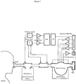
- FIG. 1 A diagram of representative elements of a pressurised gas-delivery system is shown in Figure 1 .
- Gas is drawn into a gas-delivery device through a replaceable filter system by a motor and blower assembly, the assembly being encased in a noise-dampening housing to provide quieter operation of the system.
- a flow-sensing device located in series with the gas path, may be used to detect the gas flow. Further aspects within the scope of the invention are included in the following description.
- the outer casing of the gas-delivery device including an upper case 1, a lower case 2, a first side panel 3, a second side panel opposite said first side panel (not shown), and a lid 4.
- the upper and lower casings can be engaged with suitable engagement means.
- the engagement means are screws.
- Engagement of the upper and lower casings positions the first and second side panels to form a relatively leak-proof enclosure.
- the outer casing In engaged position, the outer casing is relatively resistant to ingress of water that may be poured on the top of the gas-delivery device irrespective of the orientation of the casing.
- the lid engages the upper casing with a lid engagement means.
- the lid engagement means is preferably a snap-fit at the pivot point means.
- the pivot point means may be any suitable pivoting means such as hinges or hinge pins.
- the pivoting means may be a mechanism that includes that the instantaneous point of rotation is not fixed relative to the casing.
- An example of such a mechanism includes, but is not limited to, a four-bar linkage mechanism.
- the lid locking mechanism is preferably a latch.
- the latch is preferably spring actuated.
- the lid is also spring-actuated to enable it to open when the lid latch is disengaged.
- the spring actuating the lid preferably incorporates a rotary damper to create a smooth opening action for the lid and to avoid a "jerky" spring action that might otherwise occur.
- the pivot point can be located at the top of the casing or it can be located at the back of the casing.
- the UI is preferably constructed from a transparent lens 6 a sealing means between the upper case and the lens, and a flexible keypad 7.
- the sealing means is preferably a gasket.
- the keypad preferably includes at least one button.
- the lens engages with the upper case with a suitable engagement means.
- the lens engagement means is a snap-fit located on each side of the lens.
- the lens engagement means may be adhesive tape.
- the lens most advantageously allows the user of the gas delivery device to see through the outer case to a display which communicates information to the user.
- a further advantage of the lens is that it engages the flexible button keypad in fixed position.
- a further advantage of the engagement of the lens is a seal which prevents water ingress through the screen or button holes into the upper case.
- the flexible button keypad is preferably constructed from silicon to allow the gas-delivery device user to advantageously communicate commands to the gas-delivery device.
- the air filter is comprised of a front case 8, a back case 9 and at least a primary filter 10, illustrated in Figure 11 .
- the casing material is transparent.
- the air filter incorporates a secondary filter 11.
- the front case engages the back case to create a channel including the at least primary filter and preferably the secondary filter.
- the engagement means comprises of snap-fits. In operation of the gas-delivery device the engagement of the front case and base case creating the channel requires that gas delivered by the gas-delivery device must pass through the filter media.
- the filter media may include a primary and a secondary medium.
- the filter front case includes a plurality of holes to allow gas to flow into the primary filter and to contact the surface of the primary filter media to achieve filtering.
- the cross sectional area of the holes is greater than 400 mm 2 to avoid restricting flow into the primary filter.
- the filter back case includes an aperture which receives a connector attachment of the upper case, which in turn, provides a good seal when engaged.
- the connector attachment is a male tube.
- the filter engages with the upper casing under the lid. Most advantageously, the operation of the filter casing allows for removal and replacement of the filter. Replacement of the filter will ensure ongoing filtration of the intake air for the use of the gas-delivery device constructed according to the invention.
- the primary filter media enables the removal of large dust particles from the gas, while the secondary filter media is intended to remove smaller particles.
- media include media suitable to remove; pollen, bacteria, smoke and smog air pollution and viruses. It will be understood that the range of filter media is not limited by the preceding list.
- blower may be comprised of elements in different configurations as exemplified herein. It will be understood that other configurations are within the scope of the invention as claimed.
- the blower is constructed from a top casing 12 a bottom casing 13 and a dividing septum plate 14. These elements are engaged using screws or other engagement means to seal airtight and create a blower chamber, a motor chamber, two outlet airways and a valve chamber.
- the blower chamber houses the impeller 16 which is mounted on a shaft with bearings at each end 17.
- one bearing is press-fit into the top casing and the other is located in the bottom casing to enable it to move axially within the casing.
- a helical spring conveniently maintains an effective axial pre-load on both bearings.
- the bearings are lubricated with low-noise grease.
- the impeller 16 may have a series of fins on its top surface to move air as the impeller rotates. Between each of the fins is a small gap between the top and bottom surfaces of the impeller.
- the features allow the majority of the air flow generated by the impeller to flow out of the blower chamber into the top outlet airway (formed by the top case and the septum plate) and to create a higher pressure in this airway.
- the small holes also allow some air to flow into the bottom outlet airway (formed by the bottom case and the septum plate) and to create a reduced pressure in this airway.
- a valve member 18 then regulates the amount of air passing out of each of the top outlet airway and the bottom outlet airway. This valve 18 most advantageously can change the pressure of the overall outlet air very rapidly without the motor needing to change the speed of the impeller.
- the motor chamber contains the motor mechanism and electronics, which are held firmly in position by the bottom casing 13 and the septum plate 14.
- the blower in a second embodiment, shown in Figure 10 , includes a top case 20 and a bottom case 21 which engage to form an air-tight seal with suitable engagement means.
- the engagement means includes screws.
- the engaged cases form a blower chamber, a motor chamber, and an outlet path.
- the impeller 24 which has two bearing sets 23 mounted to either end of the blower chamber and a magnet mounted 25 to the middle of central shaft of the chamber.
- the top bearing set 23 is pressed into the top case and the bottom bearing is held radially in the bottom case and vertically by an impeller spring 22.
- the impeller and shaft 24 are moulded in one piece from a glass-filled polymer. Alternatively they may be over-moulded as a polymer onto a metal shaft.
- the top housing includes a gas inlet located above the blower chamber which allows gas into the blower chamber.
- the impeller has a series of fins located on its top surface designed to move the air to the outlet as the impeller rotates. This movement of gas creates an increase in pressure at the outlet which can be regulated by the speed of the impeller rotation.
- the bottom surface of the impeller is located in close proximity to a wall on the bottom casing which advantageously forms the motor chamber.
- the motor windings 27 and electronics 28 are firmly located in position by snap-fit or other suitable means and provide the power which drives the impeller rotation.
- the motor uses a toroidal core with no magnetic cogging.
- Three phase windings are used in star configuration, supplied with sinusoidally-modulated power (SPWM) to minimise torsional excitation.
- the rotor is comprised entirely of precision moulded plastic, which most advantageously avoids the need for an internal metal shaft and dynamic balancing.
- Electronic commutation may be phased from a single Hall Effect sensor mounted adjacent to the rotor magnet.
- the sound housing is constructed from an upper housing 56, a lower housing 57 a sealing gasket 58, two divider walls 59, inlet pipe 60, outlet pipe 61, a flexible blower attachment 62 and the blower as herein described.
- the upper and lower housings preferably are moulded or cast from a dense material to reduce sound transmission from the inside to the outside of the casing therefore contain the sound within.
- the dense material is zinc or a mineral-filled plastic.
- the upper and lower housings engage with engagement means to position the two dividing walls, the inlet tube and the outlet tube, compressing a sealing gasket around the periphery to seal air tight.
- the engagement means are screws.
- the blower Within the blower chamber is located the blower.
- the blower is mounted on two springs, top 64 and bottom 65, which ensures the blower has a low resonant frequency.
- the springs operate to reduce the transfer of vibration from the blower to the sound housing.
- a flexible pad 66 is located above the top spring and below the bottom spring.
- a flexible tube fixes the outlet to the outlet pipe 61.
- the flexible tube has corrugated sides.
- the flexible tube forms part of the sealing gasket 58.
- the flexible tube is moulded from a TPE material.
- the dividing walls 59 separate the chambers and reduce the sound transfer from one chamber to the next.
- the dividing walls may include a tube, the tube extending into the next chamber.
- the function of the tube is to carry all of the air flow between the chambers.
- the tube is located with its end a small distance, sufficient to not restrict the airflow, from the opposing wall of the next chamber.
- the opposing wall is covered in a sound deadening foam 59 or other suitable material to inhibit the sound transmission into the tube and therefore between the chambers.
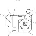
- the present invention includes a humidifier that is incorporated into the gas-delivery device enabling the gas delivery and humidifying functions to cooperate in operation of the device.
- the humidifier includes a water reservoir 30, a gas conduit connector 33, an air seal 28, a set of heating plates 31 with internal ceramic heater, and a water-reservoir heat-conductor 32. In operation, the humidifier is concealed under the lid 4.
- the water reservoir 30 is preferably comprised of a blow-moulded thermoplastic.
- the water reservoir surface includes portions that are straight and flat, the portions corresponding to receiving surfaces or rails 36 on the upper case 1. In operation, the rails ensure the water reservoir is placed correctly in the apparatus and held firmly in place. In a preferred embodiment, the water reservoir cannot be inserted into the apparatus in any other than the correct position.
- the water-reservoir heat-conductor 32 engages the upper heating plate 31 by the operation of a biasing means 38 that biases the heating plate toward the water reservoir, ensuring efficient heat transfer between the heater and the water.
- the biasing means 38 is preferably a heating plate spring.
- the metal lid may be of the type commonly found in food packaging.
- a handle 38 may extend from the water reservoir.
- the handle preferably includes at least one integrated hinge 39.
- the integrated hinge is moulded flat so that the handle automatically pops up for convenient finger access when the lid 4 is disengaged into the open position.
- the handle 38 is also convenient for carrying the water reservoir from the apparatus to a household water tap.
- the water reservoir 30 is filled with water and replaced in position in the apparatus, allowing engagement of the lid 4 into a closed position.
- the gas conduit connector 33 nests into the lid 4 to move and hinge as one component. Once the lid 4 is engaged, the outer surface of the gas conduit connector 33 is also positioned to simultaneously engage with the water reservoir air seal 28 at the water reservoir opening 29. In operation disengagement of the lid 4 also disengages the gas conduit connector 33 simultaneously from the water reservoir to enable fast and easy access and removal of the water reservoir 30.
- the gas conduit connector 33 is attached to a flexible gas conduit 40 providing pressurised gas into the gas inlet 35 and maintaining an air seal at both ends of said flexible gas conduit while the lid 4 is in the open or closed positions.
- a most advantageous aspect is the single aperture 29 for both the gas inflow and outflow from the gas-delivery device.
- a gas conduit connector 33 incorporates adjacent gas inflow conduit 35 and gas outflow conduit 34.
- the gas flow conduits are concentric tubes.
- the gas inflow conduit 35 is located inside the gas outflow conduit 34.
- a compact water reservoir is included large enough to hold adequate water to humidify enough breathing gas for a patient for a long night of sleep.
- the water reservoir is constructed so that a surface engages with the heating surface of the heater, which is disposed generally at an acute angle of approximately 45 degrees.
- the location of the aperture 29 on a surface that is generally parallel with the surface engaging the heating surface allows the gas-delivery device to be disposed can lay in a horizontal orientation, such as on a bedside table, or in a vertical orientation, such as on a wall, or any convenient intermediate orientation, without compromising the operation of the apparatus and its humidifier.
- changing the angle of the apparatus by 20 degrees in any direction off the horizontal or vertical orientation will not result in any leakage of water from the water reservoir 30.
- Figure 6 is a schematic diagram showing the operation of a humidifier.
- the temperature of the heater plate is the sole controlled variable in setting the gas humidity.
- the duty cycle of the heating element is used to control the heater plate temperature.
- a photo-coupled zero-crossing triac driver is used to turn a triac on and off under control of the micro controller.
- the photo-coupling includes the isolation from the triac driver output (at mains potential) and the micro-processor control signal. Zero-crossing switching reduces the EMI produced by the triac.
- a computer program running on the microcontroller controls the heater plate temperature to produce a user-selected humidity level.
- the gas-delivery device includes an ambient air temperature sensor and a plurality of user-requested humidity levels. The temperature of the air and the heater plate inputs, plus the air flow rate, can be used by the computer program to set the heater plate temperature.
- the gas-delivery device includes a humidity sensor for ambient air to allow more precise control of humidity.
- the humidifier is comprised of a mains-powered heater switched preferably by a triac, a thermostat attached to the heater plate, and a thermistor attached to the heating plate to provide the software with temperature feedback.
- An ambient air temperature sensor to help determine the water temperature for the user selected humidity, and a humidity sensor which may be mounted near the case extremity and shielded from heat sources inside the case.
- the gas-delivery device may include a manual reset button for the heater plate thermostat, which need not be accessible by the user, to provide over-temperature protection in the event of a fault condition.
- the gas-delivery device includes a motor and motor controller for a gas-delivery device, the motor and motor controller comprised of the major subsystems:
- Brushless DC Motors known in the art require three Hall Effect sensors to provide the required rotor position information. A method of control that requires only a single Hall Effect position sensor is described.
- the gas-delivery device includes a motor that includes three windings, the windings configured in a star topology.
- the windings are energised in a predefined sinusoidal sequence in order to initiate and maintain motor rotation.
- the duty cycle of this sequence determines how much power the motor consumes, which in turn, governs the motor speed.
- the motor drive subsystem includes the electronics necessary to power the motor windings and sense the motor current.
- the motor drive includes six MOSFETs arranged in a configuration of three half-bridge drivers. These FETs provide power to the motor windings. It also contains the necessary level translators to convert LVCMOS signals from the Motor Controller into the appropriate MOSFET drive signals.
- Motor-current sensing-circuitry illustrated in Figure 3 , is used to signal an over-current condition to the motor controller. This allows the controller to shut down the motor in the event of an over-current fault. This is implemented by a fixed-level over-current threshold detector. Two parts to the current feedback subsystem are included. A first part is a simple low-pass filter amplifier to amplify and filter the voltage over the current sense resistor. A second part is a simple comparator with hysteresis to detect an over-current fault. The output of the comparator drives directly into the motor controller.
- the motor has a single Hall Effect sensor that is used to detect the position of the rotor.
- the signal is converted to a digital value by an ADC.
- the motor controller spins the gas-delivery device motor.
- the controller causes the motor to spin at an appropriate frequency. It uses a single Hall Effect sensor to receive rotor position feedback and it uses this to generate three sinusoidal PWM drive signals.
- the motor controller includes the following inputs and outputs:
- the motor controller block diagram shown in Figure 4 is herein described as an illustration of implementation.
- the ADC Driver is an SPI interface that samples the Hall Effect Sensor ADC every 2040 clock cycles (5.1 ⁇ s). It outputs the raw rotor position as a 12-bit number and generates a sample enable signal with each new sample. This triggers the following subsystems to process the new data.
- the output of the Hall Effect sensor is a sinusoid when represented graphically.
- the graphic above the ADC Driver block in Figure 4 shows the digitised raw Hall Effect Sensor signal obtained for 1 rotor revolution.
- the 'y' axis represents the ADC value (0 to 1023). Note that the minimum value is always > 0 and the maximum is always ⁇ 1023.
- the rotor position is processed to work out the period and maximum and minimum values.
- This subsystem calculates the peak to peak amplitude (max ADC value - min ADC value) of the position-sensor raw data samples. This value is recalculated every eight motor periods.
- the current raw data sample is level shifted by subtracting min ADC value from it and output to the Normalisation subsystem as Signal Adjusted.
- Figure 4 shows the Level Shifted waveform.
- This subsystem processes the peak to peak amplitude and current Signal Adjusted sample to normalise the signal so that the position is within the range of 0 to 1023.
- Figure 4 shows the Normalised waveform.
- the normalised signal is clipped to 10 bits resolution and fed to the Period subsystem where it is processed to determine rotor period.
- Rotor period is a measure of system clocks per rotor revolution.
- the motor is commutated by a 12 sample digital sine wave oscillator which is generated from within this subsystem.
- the sine wave oscillator is phase locked to the zero crossing point.
- the current sine wave oscillator value is incremented.
- the current sine wave oscillator value is multiplied by the gain input and subsequently clipped to 10 bits.
- the gain input is a 10 bit value controlled by the microprocessor interface that includes motor speed control. If the motor speed is less than the predefined level the system gain is set to a fixed value in order to ensure reliable motor starting.
- the Period Detect subsystem calculates the rotor period in terms of system clocks per rotor revolution.
- a low-to-high most-significant-bit (msb) transition of the normalised signal input represents the zero crossing point.
- the number of system clocks between such transitions is given as the period.
- To provide a level of filtering the period value is an average of current and previous period calculations.
- the phase input allows a user selectable (via the microprocessor interface) phase shift to be added into the system. This is used to optimise motor performance and accounts for sensor position with respect to winding 1. This is an 8-bit value where a value of 128 represents a phase shift of 180 degrees.
- the phase 0 delay output contains the number of ADC samples to delay in order to obtain the required phase shift.
- the phase 120 delay output contains the number of ADC samples to wait in order to obtain a 120 degree phase shift.
- the drive signal is passed through 3 delay lines to generate the 0°, 120° and 240° drive signals.
- the 0° delay line is used to synchronise the zero crossing point to the rotor position.
- the 120° and 240° delay lines are adjusted dynamically using a third of the period to work out how much each line should be delayed.
- the three sine waves are then pulse-width modulated.
- the pulses are aligned symmetrically about a centre point. This may be done by using a triangular reference waveform, rather than the standard sawtooth reference.
- Figure 5 shows the operation of the PWM function. Each input sample is modulated by the ramp function, producing a binary output whose logic one pulse width is proportional to the magnitude of the 10 bit input sample.
- the gain setting in the Normalisation subsystem has the effect of adjusting the duty cycle of the PWM outputs.
- Each PWM signal is converted into 2 complementary drive signals, one for a N channel FET and the other for a P channel FET.
- PCBs printed circuit boards
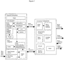
- the CPU Block is responsible for:
- the LCD Block contains an LCD display, preferably with a white LED. It is used to provide visual feedback to the user.
- the RTC uses a real-time clock chip. It will have backup power for data retention. In addition to keeping time, the clock is also used to maintain state information about the gas delivery device so that operation can be recovered in the event of a power failure.
- the EEPROM stores the calibration data for the unit. Both of these devices communicate with the CPU Block.
- the Debug/RS232 Block contains the necessary interface connector/logic for an Ethernet or RS232 transceiver for diagnostic and control purposes.
- the Keypad block includes four LED backlit buttons to control the unit.
- the buttons are arranged in a row.
- One button may function as both an on/off switch and mode selection button.
- the other buttons are option selection buttons.
- the FPGA Block includes the following functionality:
- the Buzzer Block is used to provide auditory feedback for button presses and alarms.
- the Sensor ADC includes analogue-to-digital conversion for the flow, pressure and plate temperature sensor signals.
- the pressure sensor measures the pressure of the generated airflow.
- a differential pressure technique is used to measure the rate of airflow. It includes plate temperature feedback for the humidifier controller.
- the power supply takes a DC input and generates four voltages.
- the Heater Block contains the switching mechanism and isolation for the control of the humidifier heater plate.
- the SD Card Block consists of a SD Card holder and necessary logic to interface the FPGA Block to a SD Card.
- the RS232 or Ethernet Block contains either a connector for either serial or LAN connection.
- the FPGA controls the operation of the motor.
- the CPU interface allows a microprocessor to control the FPGA.
- the Decoder is a standalone block that performs chip selection for the interface.
- the Sensor ADC Interface performs a serial to parallel conversion.
- the interface reads channels and stores the result in registers accessible via the CPU Interface.
- the Temperature interface performs a serial to parallel conversion for a temperature sensor. The temperature is stored in a register accessible via the CPU Interface.
- the Humidity Interface performs a period measurement on the humidity signal from the Main PCB of the gas delivery device. The result is accessible via the CPU Interface.
- the buzzer controller generates a square wave signal for driving a buzzer, preferably a piezo buzzer.
- the frequency and duty cycle are programmable via the CPU Interface.
- the Card Controller includes read and write buffering for accessing the card on the gas delivery device. It is designed to relieve processing from the processor.
- the main parts to the gas delivery device firmware include:
- the Kernel is the underlying OS that co-ordinates the swapping between tasks and handles low-level tasks such as interrupt handling and QSPI access.
- the Fault task is the highest priority task. It functions to monitor the motor for fault conditions and to then take appropriate actions to shutdown and report the fault.
- the Humidifier task functions to control the humidifier heater. It controls how much power is applied to the heater to produce a certain amount of humidity, based on the current ambient temperature and humidity.
- the SD Card task logs data produced by the algorithm, fault and humidifier tasks to a SD card.
- the Command task is a basic monitor program that allows the gas-delivery device to be controlled via a serial port or a 10/100 Ethernet port. The Communications task will either control a serial port or 10/100 Ethernet port.
- the Display task controls the LCD and buzzer. It also provides the alarm/clock functionality for the unit.
- the remaining four parts include sets of utility functions that provide access to various parts of the gas delivery device. These include the FPGA downloading, real-time clock interfacing, E E PROM access and FLASH/Firmware reprogramming. Table I.
Claims (12)
- Appareil pour délivrer du gaz respirable à un sujet, comprenant un boîtier (1) agencé pour recevoir un réservoir d'eau amovible (30), le réservoir d'eau étant destiné à humidifier le gaz, une soufflante (16) dans le boîtier pour mettre sous pression et délivrer le gaz humidifié, un élément chauffant pour chauffer l'eau dans le réservoir d'eau, une entrée de gaz (35) et une sortie de gaz (34) s'engageant avec un unique orifice dans le réservoir d'eau, et un conduit (33) pour diriger le gaz humidifié de la sortie jusqu'à un sujet, l'élément chauffant comprenant une surface de chauffage (31) disposée à 45 degrés par rapport à l'horizontale en utilisation, et un conducteur de chaleur (32) du réservoir d'eau étant agencé pour s'engager avec la surface de chauffage (31) en utilisation, caractérisé par le fait que l'appareil comprend un moyen de sollicitation (38) pour solliciter le conducteur de chaleur (32) du réservoir d'eau (30) contre la surface de chauffage (31) quelle que soit l'orientation de l'appareil.
- Appareil selon la revendication 1, comprenant en outre une poignée (38) s'étendant à partir du réservoir d'eau (30), la poignée comprenant au moins une charnière intégrée (39) moulée à plat de telle sorte que la poignée apparaît automatiquement pour un accès pratique aux doigts lorsqu'un couvercle (4) est désengagé dans une position ouverte.
- Appareil selon l'une ou l'autre des revendications 1 et 2, dans lequel le moyen de sollicitation (38) sollicite le conducteur de chaleur (32) du réservoir d'eau (30) contre la surface de chauffage (31) avec l'appareil dans une orientation horizontale ou une orientation verticale.
- Appareil selon l'une quelconque des revendications précédentes, comprenant en outre des rails (36) pour orienter correctement le réservoir d'eau (30) par rapport à l'appareil.
- Appareil selon l'une quelconque des revendications précédentes, comprenant en outre un filtre à gaz (10, 11) reçu dans un boîtier transparent amovible (8, 9).
- Appareil selon l'une quelconque des revendications précédentes, comprenant en outre au moins une chambre de répartition d'air et au moins un moyen de résonance adjacent à la soufflante.
- Appareil selon l'une quelconque des revendications précédentes, dans lequel le conduit (33) comprend des conduits concentriques pour un écoulement entrant de gaz (35) et un écoulement sortant de gaz (34).
- Appareil selon la revendication 7, dans lequel le conduit d'écoulement entrant de gaz comprend le conduit interne (35).
- Appareil selon l'une quelconque des revendications précédentes, comprenant en outre au moins une roue à aubes (16) pour modifier la pression ou le débit de gaz.
- Appareil selon la revendication 9, comprenant en outre un capteur pour détecter la position de la roue à aubes.
- Appareil selon l'une quelconque des revendications précédentes, comprenant en outre un moyen de signalisation de temps.
- Appareil selon la revendication 10, dans lequel le capteur est un capteur à effet Hall.
Applications Claiming Priority (2)
| Application Number | Priority Date | Filing Date | Title |
|---|---|---|---|
| AU2005905836A AU2005905836A0 (en) | 2005-10-21 | Apparatus for delivery of pressurised gas | |
| PCT/AU2006/001513 WO2007045017A2 (fr) | 2005-10-21 | 2006-10-16 | Dispositif pour la delivrance de gaz pressurise |
Publications (3)
| Publication Number | Publication Date |
|---|---|
| EP1945288A2 EP1945288A2 (fr) | 2008-07-23 |
| EP1945288A4 EP1945288A4 (fr) | 2014-03-19 |
| EP1945288B1 true EP1945288B1 (fr) | 2020-09-16 |
Family
ID=37962858
Family Applications (1)
| Application Number | Title | Priority Date | Filing Date |
|---|---|---|---|
| EP06790383.1A Active EP1945288B1 (fr) | 2005-10-21 | 2006-10-16 | Dispositif pour la delivrance de gaz pressurise |
Country Status (12)
| Country | Link |
|---|---|
| US (1) | US8985105B2 (fr) |
| EP (1) | EP1945288B1 (fr) |
| JP (2) | JP2009511218A (fr) |
| KR (2) | KR101326936B1 (fr) |
| CN (1) | CN101291703B (fr) |
| AU (2) | AU2006303868B2 (fr) |
| BR (1) | BRPI0617296A2 (fr) |
| CA (3) | CA2768869A1 (fr) |
| HK (1) | HK1123511A1 (fr) |
| IL (2) | IL190939A0 (fr) |
| NZ (2) | NZ582812A (fr) |
| WO (1) | WO2007045017A2 (fr) |
Families Citing this family (79)
| Publication number | Priority date | Publication date | Assignee | Title |
|---|---|---|---|---|
| US8739780B2 (en) | 2005-08-15 | 2014-06-03 | Resmed Limited | Low cost CPAP flow generator and humidifier assembly |
| WO2007076570A1 (fr) | 2006-01-04 | 2007-07-12 | Resmed Ltd | Appareil a soufflante silencieuse, systeme et procede de reduction du bruit d'une soufflante |
| AU2010101516A4 (en) * | 2006-11-06 | 2014-09-18 | Fisher & Paykel Healthcare Limited | Method and apparatus for increasing therapy compliance |
| JP5518480B2 (ja) | 2006-11-06 | 2014-06-11 | フィッシャー アンド ペイケル ヘルスケア リミテッド | 一体型加湿器チャンバおよびlid |
| AU2008202487B2 (en) | 2007-06-05 | 2013-07-04 | Resmed Motor Technologies Inc. | Blower with Bearing Tube |
| WO2008148151A1 (fr) * | 2007-06-08 | 2008-12-11 | Compumedics Medical Innovation Pty Ltd | Filtre à pression positive continue (cpap) |
| USD798437S1 (en) | 2007-07-30 | 2017-09-26 | Fisher & Paykel Healthcare Limited | Breathing apparatus |
| US20090107500A1 (en) * | 2007-10-25 | 2009-04-30 | Sequal Technologies, Inc. | Portable Oxygen Concentrator System and Method Including Concentrated Oxygen Flow Delivery |
| US9802022B2 (en) * | 2008-03-06 | 2017-10-31 | Resmed Limited | Humidification of respiratory gases |
| CN107715271B (zh) * | 2008-03-06 | 2023-10-24 | 瑞思迈私人有限公司 | 呼吸气体的湿化 |
| EP3075406A1 (fr) | 2008-04-30 | 2016-10-05 | ResMed R&D Germany GmbH | Appareil et procédé pour l'administration contrôlée d'un gaz respiratoire dans les voies respiratoires d'un utilisateur |
| US9505164B2 (en) | 2009-12-30 | 2016-11-29 | Schauenburg Technology Se | Tapered helically reinforced hose and its manufacture |
| DE102008022663B4 (de) | 2008-05-07 | 2012-10-31 | Schauenburg Hose Technology Gmbh | Stretch-Schlauch |
| EP3756719B1 (fr) * | 2008-05-27 | 2024-01-24 | Fisher & Paykel Healthcare Limited | Système d'assistance respiratoire pour l'administration de gaz |
| NZ708912A (en) | 2008-06-05 | 2016-12-23 | Resmed Ltd | Treatment of respiratory conditions |
| USD659235S1 (en) | 2008-06-19 | 2012-05-08 | Resmed Limited | Positive airway pressure delivery device |
| US8844522B2 (en) | 2008-09-10 | 2014-09-30 | Resmed Limited | Power management in respiratory treatment apparatus |
| CN114515373A (zh) | 2008-09-17 | 2022-05-20 | 瑞思迈私人有限公司 | 用于插入到加湿器腔室中的箱和加湿器 |
| US9964238B2 (en) | 2009-01-15 | 2018-05-08 | Globalmed, Inc. | Stretch hose and hose production method |
| AU2010206053B2 (en) * | 2009-07-31 | 2014-08-07 | ResMed Pty Ltd | Wire Heated Tube with Temperature Control System, Tube Type Detection, and Active Over Temperature Protection for Humidifier for Respiratory Apparatus |
| EP2317150B1 (fr) * | 2009-10-29 | 2019-12-18 | ResMed Pty Ltd | Dispositif de ventilation de patient et composants associés |
| US10046136B2 (en) * | 2010-06-04 | 2018-08-14 | Koninklijke Philips N.V. | Automatic humidity control in a pressure support system |
| WO2012030812A1 (fr) * | 2010-08-30 | 2012-03-08 | Itt Manufacturing Enterprises, Inc. | Système de distribution de liquide commandé électroniquement et présentant une conception modulaire de tubage et d'alimentation |
| EP2753390B1 (fr) | 2011-07-01 | 2016-11-09 | Koninklijke Philips N.V. | Système et méthode pour thérapie respiratoire à débit limité |
| EP3195892B1 (fr) | 2011-08-05 | 2019-09-25 | ResMed Motor Technologies Inc | Dispositif de ventilation à pression positive |
| US10168046B2 (en) | 2011-09-30 | 2019-01-01 | Carefusion 207, Inc. | Non-metallic humidification component |
| US9212673B2 (en) | 2011-09-30 | 2015-12-15 | Carefusion 207, Inc. | Maintaining a water level in a humidification component |
| US9289572B2 (en) | 2011-09-30 | 2016-03-22 | Carefusion 207, Inc. | Humidifying gas for respiratory therapy |
| US8733348B2 (en) | 2011-09-30 | 2014-05-27 | Carefusion 207, Inc. | Humidifying respiratory gases |
| US9067036B2 (en) | 2011-09-30 | 2015-06-30 | Carefusion 207, Inc. | Removing condensation from a breathing circuit |
| CN102488949A (zh) * | 2011-11-14 | 2012-06-13 | 王晓锋 | 一种带有空气净化功能的呼吸机 |
| GB2512192B (en) | 2012-03-06 | 2015-08-05 | Dyson Technology Ltd | A Humidifying Apparatus |
| GB2500011B (en) | 2012-03-06 | 2016-07-06 | Dyson Technology Ltd | A Humidifying Apparatus |
| GB2500012B (en) | 2012-03-06 | 2016-07-06 | Dyson Technology Ltd | A Humidifying Apparatus |
| GB2500009B (en) * | 2012-03-06 | 2015-08-05 | Dyson Technology Ltd | A Humidifying Apparatus |
| IN2014DN07603A (fr) | 2012-03-06 | 2015-05-15 | Dyson Technology Ltd | |
| GB2500017B (en) | 2012-03-06 | 2015-07-29 | Dyson Technology Ltd | A Humidifying Apparatus |
| GB2516181B (en) | 2012-03-15 | 2016-12-21 | Fisher & Paykel Healthcare Ltd | Respiratory gas humidification system |
| US9272113B2 (en) | 2012-03-30 | 2016-03-01 | Carefusion 207, Inc. | Transporting liquid in a respiratory component |
| BR112014026771B1 (pt) | 2012-04-27 | 2022-03-15 | Fisher & Paykel Healthcare Limited | Aparelho de umidificação para sistema de umidificação respiratória |
| US9289573B2 (en) | 2012-12-28 | 2016-03-22 | Covidien Lp | Ventilator pressure oscillation filter |
| EP3093575B1 (fr) | 2013-01-29 | 2018-05-09 | Dyson Technology Limited | Ensemble ventilateur |
| GB2510195B (en) | 2013-01-29 | 2016-04-27 | Dyson Technology Ltd | A fan assembly |
| US10342950B2 (en) | 2013-03-15 | 2019-07-09 | ResMed Pty Ltd | Humidifier reservoir |
| US9861778B2 (en) | 2013-03-15 | 2018-01-09 | Resmed Limited | Humidifier reservoir |
| FR3005580B1 (fr) * | 2013-05-16 | 2016-08-12 | Air Liquide Medical Systems | Appareil de ventilation artificielle a capteur de pression absolue et capteur de pression differentielle |
| WO2014184377A2 (fr) | 2013-05-17 | 2014-11-20 | Resmed Paris Sas | Diffuseur de flux et cône sonore |
| CN105579923B (zh) * | 2013-07-01 | 2019-12-06 | 瑞思迈私人有限公司 | 呼吸设备的电动机驱动系统 |
| US20150013723A1 (en) * | 2013-07-08 | 2015-01-15 | Nch Corporation | Chemical Meting System |
| GB2584025B (en) | 2013-09-13 | 2021-03-10 | Fisher & Paykel Healthcare Ltd | Heater plate for a humidification system |
| CN105764560B (zh) | 2013-09-13 | 2018-04-06 | 费雪派克医疗保健有限公司 | 用于加湿系统的连接 |
| GB2518638B (en) | 2013-09-26 | 2016-10-12 | Dyson Technology Ltd | Humidifying apparatus |
| US20160256642A1 (en) * | 2013-10-21 | 2016-09-08 | Fisher & Paykel Healthcare Limited | Breathing assistance apparatus user interface |
| JP2016540599A (ja) | 2013-12-17 | 2016-12-28 | レスメド・リミテッドResMed Limited | 呼吸圧処置システム |
| PL3082926T3 (pl) | 2013-12-20 | 2023-09-18 | Fisher & Paykel Healthcare Limited | Połączenia układu nawilżania |
| WO2015119515A1 (fr) | 2014-02-07 | 2015-08-13 | Fisher & Paykel Healthcare Limited | Système d'humidification respiratoire |
| WO2015167347A1 (fr) | 2014-05-02 | 2015-11-05 | Fisher & Paykel Healthcare Limited | Dispositif d'humidification de gaz |
| AU2015259944B2 (en) | 2014-05-13 | 2020-07-02 | Fisher & Paykel Healthcare Limited | Usability features for respiratory humidification system |
| JP6777547B2 (ja) | 2014-06-03 | 2020-10-28 | フィッシャー アンド ペイケル ヘルスケア リミテッド | 呼吸療法システム用の流れ混合器 |
| GB2528708B (en) | 2014-07-29 | 2016-06-29 | Dyson Technology Ltd | A fan assembly |
| GB2528709B (en) | 2014-07-29 | 2017-02-08 | Dyson Technology Ltd | Humidifying apparatus |
| GB2528704A (en) | 2014-07-29 | 2016-02-03 | Dyson Technology Ltd | Humidifying apparatus |
| JP6338487B2 (ja) * | 2014-08-04 | 2018-06-06 | 日本電産コパル電子株式会社 | Cpap装置 |
| EP3925654B1 (fr) | 2014-11-17 | 2024-04-17 | Fisher & Paykel Healthcare Limited | Humidification de gaz respiratoires |
| JP6741683B2 (ja) * | 2015-03-31 | 2020-08-19 | コーニンクレッカ フィリップス エヌ ヴェKoninklijke Philips N.V. | フィルタ組立体及び当該フィルタ組立体を用いた気道内圧支持システム |
| CN107847701B (zh) | 2015-07-07 | 2021-03-12 | 瑞思迈私人有限公司 | 呼吸压力治疗装置 |
| CN108025116B (zh) * | 2015-07-13 | 2021-11-23 | 康曼德公司 | 使用正压气体的手术抽吸装置 |
| EP3374013B1 (fr) * | 2015-11-10 | 2024-01-10 | Koninklijke Philips N.V. | Détermination des informations concernant le visage d'un patient |
| EP4212197A1 (fr) * | 2016-01-18 | 2023-07-19 | Fisher&Paykel Healthcare Limited | Humidification de gaz respiratoires |
| SG10202010888YA (en) * | 2016-05-02 | 2020-12-30 | Fisher & Paykel Healthcare Ltd | Humidification chamber and chamber seal for a respiratory assistance apparatus |
| CN106051173B (zh) * | 2016-07-27 | 2019-02-19 | 博雷(天津)控制系统制造有限公司 | 高压气动阀 |
| US10732081B2 (en) * | 2016-08-15 | 2020-08-04 | Veltek Associates, Inc. | Portable air sampler |
| SG10202102731PA (en) | 2016-09-28 | 2021-04-29 | Fisher & Paykel Healthcare Ltd | A yoke for headgear |
| EP4063811A1 (fr) | 2016-12-07 | 2022-09-28 | Fisher & Paykel Healthcare Limited | Capuchon pour un dispositif de détection d'un équipement médical |
| CA3033944C (fr) | 2017-01-30 | 2020-02-18 | Globalmed, Inc. | Ensemble de flexibles respiratoires chauffes |
| US11052217B2 (en) | 2017-05-17 | 2021-07-06 | ResMed Pty Ltd | Humidifier |
| US11484682B2 (en) * | 2018-09-28 | 2022-11-01 | Koninklijke Philips N.V. | Humidifier with ingress protection for use in CPAP therapy |
| WO2020239252A1 (fr) * | 2019-05-25 | 2020-12-03 | Löwenstein Medical Technology S.A. | Appareil de thérapie respiratoire et dispositif d'accouplement servant à l'accouplement d'au moins deux appareils de thérapie respiratoire |
| US20230157575A1 (en) * | 2021-11-23 | 2023-05-25 | Respiratory Sciences, Inc. | Systems for evaluating respiratory function using forced oscillation technique (fot) oscillometry |
Family Cites Families (46)
| Publication number | Priority date | Publication date | Assignee | Title |
|---|---|---|---|---|
| US4726366A (en) * | 1986-04-18 | 1988-02-23 | Life Products, Incorporated | Apparatus and method for controlling lung ventilation |
| EP0483401B1 (fr) | 1990-10-30 | 1994-10-05 | Siemens-Elema AB | Dispositif, p.ex. ventilateur pulmonaire, pour la régulation du débit d'un fluide, en particulier d'un gaz |
| US5380267A (en) * | 1993-06-18 | 1995-01-10 | Datascope Investment Corp. | Noise-attenuating pneumatic compressor and medical apparatus incorporating same |
| FI100307B (fi) * | 1994-02-25 | 1997-11-14 | Kemira Safety Oy | Menetelmä kaasunaamariin syötetyn ilmamäärän säätämiseksi sekä kaasuna amari |
| WO1995024071A1 (fr) * | 1994-03-03 | 1995-09-08 | Iomega Corporation | Controleur de servomoteur fonctionnant par interpolation des positions |
| IT1272858B (it) * | 1995-01-03 | 1997-07-01 | Dar Spa | Umidificatore attivo monouso particolarmente per linee inspiratorie di circuiti respiratori per terapia intensiva |
| AUPN394895A0 (en) * | 1995-07-03 | 1995-07-27 | Rescare Limited | Auto-calibration of pressure transducer offset |
| AUPN547895A0 (en) | 1995-09-15 | 1995-10-12 | Rescare Limited | Flow estimation and compenstion of flow-induced pressure swings cpap treatment |
| US5865173A (en) | 1995-11-06 | 1999-02-02 | Sunrise Medical Hhg Inc. | Bilevel CPAP system with waveform control for both IPAP and EPAP |
| KR100258434B1 (ko) * | 1996-09-02 | 2000-06-01 | 윤종용 | 1-홀 신호를 이용한 3상 비엘디시 모터의 구동회로 |
| US6439231B1 (en) * | 1996-11-18 | 2002-08-27 | Medlis Corp. | Artificial ventilation systems and components thereof, and methods for providing, assembling and utilizing same |
| JP4005654B2 (ja) * | 1996-12-26 | 2007-11-07 | Ntn株式会社 | 磁気浮上型遠心式ポンプ装置 |
| AUPP015097A0 (en) * | 1997-11-03 | 1997-11-27 | Resmed Limited | A mounting body |
| US6321748B1 (en) * | 1998-03-10 | 2001-11-27 | Nellcor Puritan Bennett | Closed loop control in a piston ventilator |
| JP3689567B2 (ja) * | 1998-09-29 | 2005-08-31 | 京セラ株式会社 | 遠心型血液ポンプ |
| DE29817685U1 (de) | 1998-10-05 | 1999-05-06 | Hoffrichter Helmut | Kopplungsgerät für ein Beatmungsgerät mit Befeuchter |
| JP3971520B2 (ja) * | 1998-10-14 | 2007-09-05 | 東芝キヤリア株式会社 | 空気調和機の室外ファン用ブラシレスモータの駆動装置 |
| TW451543B (en) * | 1999-12-10 | 2001-08-21 | Acer Peripherals Inc | Brushless motor system with capacitors |
| DE19962516C2 (de) * | 1999-12-23 | 2002-04-18 | Map Gmbh | Vorrichtung zur Zufuhr eines Atemgases |
| US6349724B1 (en) * | 2000-07-05 | 2002-02-26 | Compumedics Sleep Pty. Ltd. | Dual-pressure blower for positive air pressure device |
| JP2002017302A (ja) * | 2000-07-10 | 2002-01-22 | Itoham Foods Inc | 牛肉調製品およびその製造方法 |
| US6644310B1 (en) | 2000-09-29 | 2003-11-11 | Mallinckrodt Inc. | Apparatus and method for providing a breathing gas employing a bi-level flow generator with an AC synchronous motor |
| JP2004511311A (ja) * | 2000-10-19 | 2004-04-15 | マリンクロッド・インコーポレイテッド | 二重気体供給部を備える人工呼吸器 |
| EP1359962B1 (fr) * | 2001-02-16 | 2016-08-17 | ResMed Limited | Humidificateur dote d'une structure destinee a empecher le refoulement de liquide par l'entree de l'humidificateur |
| EP1359963B1 (fr) * | 2001-02-16 | 2013-07-17 | ResMed Limited | Surveillance d'un signal de pression d'air dans un appareil de traitement des evenements respiratoires du sommeil |
| US20020134378A1 (en) * | 2001-03-26 | 2002-09-26 | Finnegan Linda A. | Sound dampening housing for respiratory assist devices |
| JP3546866B2 (ja) * | 2001-08-20 | 2004-07-28 | 三菱電機株式会社 | 車両用始動充電回転電機 |
| US20030111077A1 (en) * | 2001-12-17 | 2003-06-19 | Hooser Theron Van | Patient humidification systems |
| US6968842B1 (en) | 2002-04-03 | 2005-11-29 | Ric Investments, Inc. | Measurement of a fluid parameter in a pressure support system |
| US6953354B2 (en) * | 2002-06-05 | 2005-10-11 | Fisher & Paykel Healthcare Limited | Connector for breathing conduits |
| DE10226160B4 (de) | 2002-06-12 | 2009-06-18 | Hoffrichter Gmbh | Luftbefeuchter für ein Beatmungsgerät |
| DE20213232U1 (de) | 2002-08-23 | 2003-03-20 | Euromed Medical Partners Gmbh | Geräuschdämmendes Gehäuse zur Aufnahme einer Turbine |
| EP1542757B1 (fr) | 2002-09-17 | 2020-01-15 | Fisher & Paykel Healthcare Limited | Appareil d'administration de gaz humidifies |
| DE10253937B3 (de) * | 2002-11-19 | 2004-01-15 | Seleon Gmbh | Lüftereinheiten für ein Beatmungsgerät |
| US20040226562A1 (en) * | 2002-12-06 | 2004-11-18 | Bordewick Steven S. | Blower assembly for CPAP |
| DE10322431B4 (de) * | 2003-05-19 | 2021-07-01 | Löwenstein Medical Technology S.A. | Verfahren zur Zufuhr von Atemgas sowie Vorrichtung zur Beatmung |
| WO2004112879A1 (fr) | 2003-06-20 | 2004-12-29 | Coloplast A/S | Dispositif medical comportant une partie tressee |
| AU2003903139A0 (en) * | 2003-06-20 | 2003-07-03 | Resmed Limited | Breathable gas apparatus with humidifier |
| US20040257071A1 (en) * | 2003-06-20 | 2004-12-23 | Jack Chen | Angular position sensor |
| WO2005011785A1 (fr) * | 2003-08-01 | 2005-02-10 | Fisher & Paykel Healthcare Limited | Dispositif de distribution de gaz respiratoire equipe d'un humidificateur integre |
| WO2005016217A2 (fr) | 2003-08-04 | 2005-02-24 | Pulmonetic Systems, Inc. | Systeme de commande de compresseur pour un ventilateur portable |
| US7607437B2 (en) * | 2003-08-04 | 2009-10-27 | Cardinal Health 203, Inc. | Compressor control system and method for a portable ventilator |
| US20050121989A1 (en) * | 2003-12-05 | 2005-06-09 | Asmo Co., Ltd. | Brushless motor having claw pole type stator |
| US6982532B2 (en) * | 2003-12-08 | 2006-01-03 | A. O. Smith Corporation | Electric machine |
| DE102005063661B3 (de) * | 2004-02-20 | 2023-08-17 | Löwenstein Medical Technology S.A. | Modulare Vorrichtung zur Befeuchtung von Atemgas |
| WO2005097248A1 (fr) * | 2004-04-05 | 2005-10-20 | Breas Medical Ab | Valve de regulation pour ventilateur |
-
2006
- 2006-10-16 KR KR1020137004564A patent/KR101326936B1/ko active IP Right Grant
- 2006-10-16 CA CA2768869A patent/CA2768869A1/fr not_active Abandoned
- 2006-10-16 AU AU2006303868A patent/AU2006303868B2/en not_active Ceased
- 2006-10-16 CA CA2625534A patent/CA2625534C/fr active Active
- 2006-10-16 CA CA2688920A patent/CA2688920C/fr active Active
- 2006-10-16 US US12/091,060 patent/US8985105B2/en active Active - Reinstated
- 2006-10-16 BR BRPI0617296-2A patent/BRPI0617296A2/pt not_active IP Right Cessation
- 2006-10-16 JP JP2008535841A patent/JP2009511218A/ja active Pending
- 2006-10-16 NZ NZ582812A patent/NZ582812A/en not_active IP Right Cessation
- 2006-10-16 WO PCT/AU2006/001513 patent/WO2007045017A2/fr active Application Filing
- 2006-10-16 NZ NZ566721A patent/NZ566721A/en not_active IP Right Cessation
- 2006-10-16 KR KR1020087008279A patent/KR101340812B1/ko active IP Right Grant
- 2006-10-16 CN CN2006800393254A patent/CN101291703B/zh active Active
- 2006-10-16 EP EP06790383.1A patent/EP1945288B1/fr active Active
-
2008
- 2008-04-17 IL IL190939A patent/IL190939A0/en not_active IP Right Cessation
-
2009
- 2009-01-07 HK HK09100113.3A patent/HK1123511A1/xx not_active IP Right Cessation
-
2010
- 2010-02-23 AU AU2010200652A patent/AU2010200652B2/en not_active Ceased
-
2012
- 2012-08-08 IL IL221358A patent/IL221358A/en not_active IP Right Cessation
-
2013
- 2013-04-04 JP JP2013078918A patent/JP5750135B2/ja active Active
Non-Patent Citations (1)
| Title |
|---|
| None * |
Also Published As
| Publication number | Publication date |
|---|---|
| JP5750135B2 (ja) | 2015-07-15 |
| AU2006303868A1 (en) | 2007-04-26 |
| KR101326936B1 (ko) | 2013-11-11 |
| NZ582812A (en) | 2010-05-28 |
| AU2006303868B2 (en) | 2010-05-27 |
| CA2688920C (fr) | 2012-04-10 |
| KR101340812B1 (ko) | 2013-12-11 |
| CA2768869A1 (fr) | 2007-04-26 |
| AU2010200652A1 (en) | 2010-03-18 |
| KR20080057261A (ko) | 2008-06-24 |
| IL221358A0 (en) | 2012-09-24 |
| HK1123511A1 (en) | 2009-06-19 |
| IL221358A (en) | 2015-10-29 |
| US20090301482A1 (en) | 2009-12-10 |
| NZ566721A (en) | 2010-03-26 |
| EP1945288A4 (fr) | 2014-03-19 |
| JP2009511218A (ja) | 2009-03-19 |
| CN101291703A (zh) | 2008-10-22 |
| WO2007045017A2 (fr) | 2007-04-26 |
| CA2625534C (fr) | 2010-02-23 |
| CA2688920A1 (fr) | 2007-04-26 |
| BRPI0617296A2 (pt) | 2013-02-26 |
| KR20130023408A (ko) | 2013-03-07 |
| CA2625534A1 (fr) | 2007-04-26 |
| JP2013165974A (ja) | 2013-08-29 |
| AU2010200652B2 (en) | 2013-01-10 |
| EP1945288A2 (fr) | 2008-07-23 |
| WO2007045017A3 (fr) | 2007-07-12 |
| CN101291703B (zh) | 2012-07-04 |
| US8985105B2 (en) | 2015-03-24 |
| IL190939A0 (en) | 2009-09-22 |
Similar Documents
| Publication | Publication Date | Title |
|---|---|---|
| EP1945288B1 (fr) | Dispositif pour la delivrance de gaz pressurise | |
| US11617849B2 (en) | Sensing and control arrangements for respiratory device | |
| US20210016030A1 (en) | Electronic apparatus control using a breathing assistance apparatus | |
| JP5666406B2 (ja) | 閉塞性睡眠時無呼吸を治療するための装置 | |
| US20180110946A1 (en) | Air impeller device for providing assisted ventilation during spontaneous breathing | |
| AU2022275459A1 (en) | Humidifier | |
| EP3833419A1 (fr) | Ensemble plaque chauffante dans des systèmes d'humidificateur à usage médical | |
| AU2013201512A1 (en) | Apparatus for Delivery of Pressurised Gas |
Legal Events
| Date | Code | Title | Description |
|---|---|---|---|
| PUAI | Public reference made under article 153(3) epc to a published international application that has entered the european phase |
Free format text: ORIGINAL CODE: 0009012 |
|
| 17P | Request for examination filed |
Effective date: 20080519 |
|
| AK | Designated contracting states |
Kind code of ref document: A2 Designated state(s): AT BE BG CH CY CZ DE DK EE ES FI FR GB GR HU IE IS IT LI LT LU LV MC NL PL PT RO SE SI SK TR |
|
| DAX | Request for extension of the european patent (deleted) | ||
| A4 | Supplementary search report drawn up and despatched |
Effective date: 20140214 |
|
| RIC1 | Information provided on ipc code assigned before grant |
Ipc: A61M 16/16 20060101AFI20140210BHEP |
|
| RAP1 | Party data changed (applicant data changed or rights of an application transferred) |
Owner name: COMPUMEDICS MEDICAL INNOVATION PTY LTD |
|
| STAA | Information on the status of an ep patent application or granted ep patent |
Free format text: STATUS: EXAMINATION IS IN PROGRESS |
|
| 17Q | First examination report despatched |
Effective date: 20170213 |
|
| REG | Reference to a national code |
Ref country code: DE Ref legal event code: R079 Ref document number: 602006059677 Country of ref document: DE Free format text: PREVIOUS MAIN CLASS: A61M0016000000 Ipc: A61M0016160000 |
|
| RIC1 | Information provided on ipc code assigned before grant |
Ipc: A61M 16/10 20060101ALI20171122BHEP Ipc: A61M 16/00 20060101ALI20171122BHEP Ipc: A61M 16/16 20060101AFI20171122BHEP |
|
| GRAP | Despatch of communication of intention to grant a patent |
Free format text: ORIGINAL CODE: EPIDOSNIGR1 |
|
| STAA | Information on the status of an ep patent application or granted ep patent |
Free format text: STATUS: GRANT OF PATENT IS INTENDED |
|
| INTG | Intention to grant announced |
Effective date: 20200415 |
|
| GRAS | Grant fee paid |
Free format text: ORIGINAL CODE: EPIDOSNIGR3 |
|
| GRAA | (expected) grant |
Free format text: ORIGINAL CODE: 0009210 |
|
| STAA | Information on the status of an ep patent application or granted ep patent |
Free format text: STATUS: THE PATENT HAS BEEN GRANTED |
|
| AK | Designated contracting states |
Kind code of ref document: B1 Designated state(s): AT BE BG CH CY CZ DE DK EE ES FI FR GB GR HU IE IS IT LI LT LU LV MC NL PL PT RO SE SI SK TR |
|
| REG | Reference to a national code |
Ref country code: GB Ref legal event code: FG4D |
|
| REG | Reference to a national code |
Ref country code: CH Ref legal event code: EP |
|
| REG | Reference to a national code |
Ref country code: DE Ref legal event code: R096 Ref document number: 602006059677 Country of ref document: DE |
|
| REG | Reference to a national code |
Ref country code: IE Ref legal event code: FG4D |
|
| REG | Reference to a national code |
Ref country code: AT Ref legal event code: REF Ref document number: 1313591 Country of ref document: AT Kind code of ref document: T Effective date: 20201015 |
|
| PG25 | Lapsed in a contracting state [announced via postgrant information from national office to epo] |
Ref country code: GR Free format text: LAPSE BECAUSE OF FAILURE TO SUBMIT A TRANSLATION OF THE DESCRIPTION OR TO PAY THE FEE WITHIN THE PRESCRIBED TIME-LIMIT Effective date: 20201217 Ref country code: FI Free format text: LAPSE BECAUSE OF FAILURE TO SUBMIT A TRANSLATION OF THE DESCRIPTION OR TO PAY THE FEE WITHIN THE PRESCRIBED TIME-LIMIT Effective date: 20200916 Ref country code: SE Free format text: LAPSE BECAUSE OF FAILURE TO SUBMIT A TRANSLATION OF THE DESCRIPTION OR TO PAY THE FEE WITHIN THE PRESCRIBED TIME-LIMIT Effective date: 20200916 Ref country code: BG Free format text: LAPSE BECAUSE OF FAILURE TO SUBMIT A TRANSLATION OF THE DESCRIPTION OR TO PAY THE FEE WITHIN THE PRESCRIBED TIME-LIMIT Effective date: 20201216 |
|
| REG | Reference to a national code |
Ref country code: AT Ref legal event code: MK05 Ref document number: 1313591 Country of ref document: AT Kind code of ref document: T Effective date: 20200916 |
|
| REG | Reference to a national code |
Ref country code: NL Ref legal event code: MP Effective date: 20200916 |
|
| PG25 | Lapsed in a contracting state [announced via postgrant information from national office to epo] |
Ref country code: LV Free format text: LAPSE BECAUSE OF FAILURE TO SUBMIT A TRANSLATION OF THE DESCRIPTION OR TO PAY THE FEE WITHIN THE PRESCRIBED TIME-LIMIT Effective date: 20200916 |
|
| REG | Reference to a national code |
Ref country code: LT Ref legal event code: MG4D |
|
| PG25 | Lapsed in a contracting state [announced via postgrant information from national office to epo] |
Ref country code: EE Free format text: LAPSE BECAUSE OF FAILURE TO SUBMIT A TRANSLATION OF THE DESCRIPTION OR TO PAY THE FEE WITHIN THE PRESCRIBED TIME-LIMIT Effective date: 20200916 Ref country code: CZ Free format text: LAPSE BECAUSE OF FAILURE TO SUBMIT A TRANSLATION OF THE DESCRIPTION OR TO PAY THE FEE WITHIN THE PRESCRIBED TIME-LIMIT Effective date: 20200916 Ref country code: LT Free format text: LAPSE BECAUSE OF FAILURE TO SUBMIT A TRANSLATION OF THE DESCRIPTION OR TO PAY THE FEE WITHIN THE PRESCRIBED TIME-LIMIT Effective date: 20200916 Ref country code: PT Free format text: LAPSE BECAUSE OF FAILURE TO SUBMIT A TRANSLATION OF THE DESCRIPTION OR TO PAY THE FEE WITHIN THE PRESCRIBED TIME-LIMIT Effective date: 20210118 Ref country code: NL Free format text: LAPSE BECAUSE OF FAILURE TO SUBMIT A TRANSLATION OF THE DESCRIPTION OR TO PAY THE FEE WITHIN THE PRESCRIBED TIME-LIMIT Effective date: 20200916 Ref country code: RO Free format text: LAPSE BECAUSE OF FAILURE TO SUBMIT A TRANSLATION OF THE DESCRIPTION OR TO PAY THE FEE WITHIN THE PRESCRIBED TIME-LIMIT Effective date: 20200916 |
|
| PG25 | Lapsed in a contracting state [announced via postgrant information from national office to epo] |
Ref country code: IS Free format text: LAPSE BECAUSE OF FAILURE TO SUBMIT A TRANSLATION OF THE DESCRIPTION OR TO PAY THE FEE WITHIN THE PRESCRIBED TIME-LIMIT Effective date: 20210116 Ref country code: ES Free format text: LAPSE BECAUSE OF FAILURE TO SUBMIT A TRANSLATION OF THE DESCRIPTION OR TO PAY THE FEE WITHIN THE PRESCRIBED TIME-LIMIT Effective date: 20200916 Ref country code: AT Free format text: LAPSE BECAUSE OF FAILURE TO SUBMIT A TRANSLATION OF THE DESCRIPTION OR TO PAY THE FEE WITHIN THE PRESCRIBED TIME-LIMIT Effective date: 20200916 Ref country code: PL Free format text: LAPSE BECAUSE OF FAILURE TO SUBMIT A TRANSLATION OF THE DESCRIPTION OR TO PAY THE FEE WITHIN THE PRESCRIBED TIME-LIMIT Effective date: 20200916 |
|
| REG | Reference to a national code |
Ref country code: CH Ref legal event code: PL |
|
| REG | Reference to a national code |
Ref country code: DE Ref legal event code: R097 Ref document number: 602006059677 Country of ref document: DE |
|
| PG25 | Lapsed in a contracting state [announced via postgrant information from national office to epo] |
Ref country code: LU Free format text: LAPSE BECAUSE OF NON-PAYMENT OF DUE FEES Effective date: 20201016 Ref country code: SK Free format text: LAPSE BECAUSE OF FAILURE TO SUBMIT A TRANSLATION OF THE DESCRIPTION OR TO PAY THE FEE WITHIN THE PRESCRIBED TIME-LIMIT Effective date: 20200916 Ref country code: MC Free format text: LAPSE BECAUSE OF FAILURE TO SUBMIT A TRANSLATION OF THE DESCRIPTION OR TO PAY THE FEE WITHIN THE PRESCRIBED TIME-LIMIT Effective date: 20200916 |
|
| REG | Reference to a national code |
Ref country code: BE Ref legal event code: MM Effective date: 20201031 |
|
| PLBE | No opposition filed within time limit |
Free format text: ORIGINAL CODE: 0009261 |
|
| STAA | Information on the status of an ep patent application or granted ep patent |
Free format text: STATUS: NO OPPOSITION FILED WITHIN TIME LIMIT |
|
| 26N | No opposition filed |
Effective date: 20210617 |
|
| PG25 | Lapsed in a contracting state [announced via postgrant information from national office to epo] |
Ref country code: SI Free format text: LAPSE BECAUSE OF FAILURE TO SUBMIT A TRANSLATION OF THE DESCRIPTION OR TO PAY THE FEE WITHIN THE PRESCRIBED TIME-LIMIT Effective date: 20200916 Ref country code: LI Free format text: LAPSE BECAUSE OF NON-PAYMENT OF DUE FEES Effective date: 20201031 Ref country code: DK Free format text: LAPSE BECAUSE OF FAILURE TO SUBMIT A TRANSLATION OF THE DESCRIPTION OR TO PAY THE FEE WITHIN THE PRESCRIBED TIME-LIMIT Effective date: 20200916 Ref country code: BE Free format text: LAPSE BECAUSE OF NON-PAYMENT OF DUE FEES Effective date: 20201031 Ref country code: CH Free format text: LAPSE BECAUSE OF NON-PAYMENT OF DUE FEES Effective date: 20201031 |
|
| PG25 | Lapsed in a contracting state [announced via postgrant information from national office to epo] |
Ref country code: IT Free format text: LAPSE BECAUSE OF FAILURE TO SUBMIT A TRANSLATION OF THE DESCRIPTION OR TO PAY THE FEE WITHIN THE PRESCRIBED TIME-LIMIT Effective date: 20200916 Ref country code: IE Free format text: LAPSE BECAUSE OF NON-PAYMENT OF DUE FEES Effective date: 20201016 |
|
| PG25 | Lapsed in a contracting state [announced via postgrant information from national office to epo] |
Ref country code: TR Free format text: LAPSE BECAUSE OF FAILURE TO SUBMIT A TRANSLATION OF THE DESCRIPTION OR TO PAY THE FEE WITHIN THE PRESCRIBED TIME-LIMIT Effective date: 20200916 Ref country code: CY Free format text: LAPSE BECAUSE OF FAILURE TO SUBMIT A TRANSLATION OF THE DESCRIPTION OR TO PAY THE FEE WITHIN THE PRESCRIBED TIME-LIMIT Effective date: 20200916 |
|
| PGFP | Annual fee paid to national office [announced via postgrant information from national office to epo] |
Ref country code: GB Payment date: 20231004 Year of fee payment: 18 |
|
| PGFP | Annual fee paid to national office [announced via postgrant information from national office to epo] |
Ref country code: FR Payment date: 20231023 Year of fee payment: 18 Ref country code: DE Payment date: 20231005 Year of fee payment: 18 |