EP1945062B1 - Multi-user desk system - Google Patents
Multi-user desk system Download PDFInfo
- Publication number
- EP1945062B1 EP1945062B1 EP06779656A EP06779656A EP1945062B1 EP 1945062 B1 EP1945062 B1 EP 1945062B1 EP 06779656 A EP06779656 A EP 06779656A EP 06779656 A EP06779656 A EP 06779656A EP 1945062 B1 EP1945062 B1 EP 1945062B1
- Authority
- EP
- European Patent Office
- Prior art keywords
- desk
- capsule
- user
- moveable
- support frame
- Prior art date
- Legal status (The legal status is an assumption and is not a legal conclusion. Google has not performed a legal analysis and makes no representation as to the accuracy of the status listed.)
- Not-in-force
Links
Images


Classifications
-
- A—HUMAN NECESSITIES
- A47—FURNITURE; DOMESTIC ARTICLES OR APPLIANCES; COFFEE MILLS; SPICE MILLS; SUCTION CLEANERS IN GENERAL
- A47B—TABLES; DESKS; OFFICE FURNITURE; CABINETS; DRAWERS; GENERAL DETAILS OF FURNITURE
- A47B51/00—Cabinets with means for moving compartments up and down
-
- A—HUMAN NECESSITIES
- A47—FURNITURE; DOMESTIC ARTICLES OR APPLIANCES; COFFEE MILLS; SPICE MILLS; SUCTION CLEANERS IN GENERAL
- A47B—TABLES; DESKS; OFFICE FURNITURE; CABINETS; DRAWERS; GENERAL DETAILS OF FURNITURE
- A47B17/00—Writing-tables
-
- A—HUMAN NECESSITIES
- A47—FURNITURE; DOMESTIC ARTICLES OR APPLIANCES; COFFEE MILLS; SPICE MILLS; SUCTION CLEANERS IN GENERAL
- A47B—TABLES; DESKS; OFFICE FURNITURE; CABINETS; DRAWERS; GENERAL DETAILS OF FURNITURE
- A47B46/00—Cabinets, racks or shelf units, having one or more surfaces adapted to be brought into position for use by extending or pivoting
-
- A—HUMAN NECESSITIES
- A47—FURNITURE; DOMESTIC ARTICLES OR APPLIANCES; COFFEE MILLS; SPICE MILLS; SUCTION CLEANERS IN GENERAL
- A47B—TABLES; DESKS; OFFICE FURNITURE; CABINETS; DRAWERS; GENERAL DETAILS OF FURNITURE
- A47B83/00—Combinations comprising two or more pieces of furniture of different kinds
- A47B83/001—Office desks or work-stations combined with other pieces of furniture, e.g. work space management systems
-
- A—HUMAN NECESSITIES
- A47—FURNITURE; DOMESTIC ARTICLES OR APPLIANCES; COFFEE MILLS; SPICE MILLS; SUCTION CLEANERS IN GENERAL
- A47B—TABLES; DESKS; OFFICE FURNITURE; CABINETS; DRAWERS; GENERAL DETAILS OF FURNITURE
- A47B9/00—Tables with tops of variable height
- A47B9/12—Tables with tops of variable height with flexible height-adjusting means, e.g. rope, chain
Definitions
- the present invention relates to a multi-user desk system, in particular a desk apparatus for simultaneous use by one or more people.
- the desks are also generally provided with network connections so a user may plug their laptop into the office network. When they have finished the user simply collects their items leaving the desk free for the next user to use when required. This means that the desk is either voluntarily cleared by the departing user or involuntarily cleared by the next user.
- This system of multiple users saves space and because usually only one or two users of a desk are in the office at one time, the system is tolerated but not always appreciated since the desks cannot be personalized for each user.
- a further problem associated with this kind of system is that there is no scope for leaving a user's paperwork or office consumables etc. laid out on the desk for extended periods. Items which might look unimportant to one person and are cleared away, may be crucial to another - but then can not be found or even remembered again easily. Also the desk users often dislike the lack of personalized space and find that such desk systems provide an uncomfortable working environment when compared with more traditional office furniture arrangements.
- the present invention seeks to address the problems mentioned above and provide an improved multi-user desk system and storage apparatus.
- a multi-user desk apparatus comprising:
- the plurality of desk capsules are each slidably mountable within and removable from a respective chamber to the at least one moveable desk capsule support frame.
- each desk capsule is slidably removable from front, rear or side sections of the frame.
- the plurality of desk capsules are vertically stackable within the frame.
- the at least one moveable desk capsule support frame is adjustable for height to facilitate removal of any of the stacked plurality of desk capsules.
- a pulley and cable system provides the height adjustment means.
- the height adjustment means is motorised.
- the motorised height adjustment means is programmable and further comprises a series of sensors to facilitate precise positioning of a moveable desk capsule support frame operatively-adjacent a desk capsule-receiving chamber.
- the moveable desk capsule support frame is slidably engageable and mountable within vertical channels formed in the apparatus frame.
- the vertical channels are formed at corners of the apparatus frame.
- the moveable desk capsule support frame is hingedly mountable within the channel of the apparatus frame to allow the support frame to be folded against the apparatus frame for storage or when not in use.
- the moveable desk capsule support frame further comprises at least one support leg.
- the moveable desk capsule support frame further comprises two support legs.
- the moveable desk capsule support frame is demountable with the hinge attachment and comprises four support legs.
- the support legs are adjustable for height.
- the support legs further comprise wheels.
- the desk capsule is demountable from the moveable desk capsule support frame and engageable with at least one wheeled support element.
- desk capsule further comprises slots or channels in an underside thereof and with which the at least one wheeled support element is engageable.
- the at least one wheeled support element lockingly engages with the slots or channels of the desk capsule.
- two moveable desk capsule support frames are provided for simultaneous use.
- three moveable desk capsule support frames are provided for simultaneous use.
- a demountable moveable desk capsule support frame is provided for each desk capsule.
- the multi-user desk apparatus further comprises vertical privacy panels.
- the privacy panels are hingedly attached to the apparatus frame.
- the privacy panels are demountable.
- the support frame further comprises electrical service means.
- the electrical service means comprises an electrical power supply and computer network and telephone connections.
- the multi-user desk apparatus comprises a modular system, wherein the top mechanism-containing panel, the front, back and side framework pieces, secrecy panels, moveable desk capsule support frame(s), and the desk capsules are supplied as single piece units for on-site construction.
- the modular system can be stored in a 'flat-pack' arrangement.
- Figure 1 shows a multi user desk apparatus with a number of stored desk capsules inside a desk storage frame, in which one desk capsule is open and ready for work, one desk capsule to the front closed, and one support frame to the right as seen in the Figure is empty for receipt of a stored desk capsule.
- the apparatus comprises a generally rectangular apparatus frame 10, divided into a plurality of chambers or storage compartments each for housing a desk capsule 11.
- the desk capsules 11 are slidably mounted on sliding means in the form of track, rollers or an air cushion arrangement of the apparatus frame 10.
- the apparatus frame 10 further comprises movable support frames 12 which support desk capsules 11 when in a deployed position.
- the desk apparatus is provided with three movable support frames 12 in which two are shown in receipt of deployed desk capsules, and one is vacant.
- the moveable support frames 12 are pivotally attached to apparatus frame 10 through a moveable hinge assembly 13 which allows the frame to be folded against the apparatus frame 10 when it is not required, and also for storage purposes.
- moveable support frames 12 are provided with service connecting means 14 so that a user can connect to a power supply, phone socket or the office network.
- Towards the front of the multi-user desk apparatus of Figure 1 is shown a closed desk capsule on the front located moveable support frame. To left and right sides of the desk are mounted modesty or privacy panels 15. The privacy panels may be removable or pivotally attached to the apparatus frame 10.
- the moveable hinge 13 locates within a vertical channel at an outside edge of apparatus frame 10 and is adjustable for height. As illustrated in Figures 2 and 3 (and further discussed below) a pulley system enables vertical movement of the hinge 13 and consequently moveable support frame 12.
- the support frame 12 is permanently attached through hinge 13 to apparatus frame 10 and may be provided with support legs. Preferably these are foldably incorporated into the support frame to provide added stability to a desk thus formed.
- the moveable support frame is demountable and the support legs are preferably fitted with wheels to allow a desk formed from a desk capsule and the moveable support frame to be moved to a location remote from the desk apparatus frame.
- separate wheeled support elements are engageable with the underside of a desk capsule and the capsule and wheeled support element are demountable from a moveable support frame 12 for use at a location remote from the desk apparatus frame.
- Each desk capsule 11 comprises a boxed unit with hingedly attached lid 20.
- the capsule lid In use, the capsule lid is raised and is lockable in an upright position to prevent the lid falling on a user.
- the base of the capsule 11 comprises a work surface 21 which may be adapted to suit a particular expected end use of an individual user.
- the lid 20 also comprises a desk lamp 22 and notice/pin board 23.
- Each desk capsule also comprises a post box 24 in a front wall and lid of the capsule 11 for private memos or mail delivery.
- FIG 2 illustrates a partial section through moveable support frame 12 showing a vertical guide rail 25 of the apparatus frame 10 in which a carriage 34, comprising moveable hinge 13 and linked frame 12, is located.
- Carriage 34 is supported within guide rail 25 by bearing wheels 30 and is attached at a top edge to a lifting cable 31.
- Lifting cable 31 in turn links to a pulley system ( Figure 3 ) via a dead block 32, located towards the top of guide rail 25 and mounted upon apparatus frame 10, and a further dead block 33, located on the top of apparatus frame 10.
- the carriage 34 is vertically moveable up and down inside the vertical guide rail 25.
- the moveable support frame 12 may be demountable at hinge 13, for ease of installation/convenience when not in use or to facilitate demounting of a horizontal support frame having integral support legs and a desk capsule loaded thereon for use remote from the main apparatus frame 10 if required.
- a wheeled support element is engaged with a desk capsule and the capsule removed from moveable support frame 12, as described in greater detail below in relation to Figures 5 and 6 .
- the moveable support frame is fitted with rollers 35 along an inside edge of the support frame 12.
- the rollers 35 may be motorised for automatic operation if required (not shown) or other similar devices to enable easy sliding of the desk capsules on to and off the moveable support frame may also be provided.
- lifting cable 31, attached to the carriage 34 of Figure 2 is linked to a motor/gearbox assembly 40 through a pulley/drive mechanism 41 which is located on an upper surface of apparatus frame 10.
- Pulley/drive mechanism 41 comprises a rotatable shaft 42 linked at one end through a thrust bearing 43 to motor/gearbox assembly 40.
- Rotatable shaft 42 is at least partially threaded from its opposite end and is screwably engaged with a follower carriage 44.
- the follower carriage further comprises a pair of follower pulleys 45, through which the respective ends of cable 31 pass.
- the ends of cable 31 are anchored to the apparatus frame 10 at anchor points 50, which are provided with adjustment means for adjusting the cable length (not shown).
- motor/gearbox assembly 40 is operated to rotate shaft 42 and drive follower carriage 44 by means of the pulley/drive mechanism 41.
- follower carriage 44 moves along shaft 42 to raise or lower the height of desk carriage 34.
- cable 31 is drawn so that desk carriage 34 is raised relative to the floor surface.
- the follower carriage 44 moves away from motor/gearbox assembly 40, cable 31 is let out by the pulley/drive mechanism and the desk carriage 34 is lowered.
- Position location detectors 51 located on an upper surface of the apparatus frame 10, detect the relative location of the threaded follower carriage 44 so that the relative height of a capsule 11 located within a moveable support frame 12 can be calibrated and set. By this means, specific height adjustment can be made so that the carriage 34 can be accurately positioned adjacent a particular desk capsule 11 bay (antecedent). In alternative embodiments (not shown), position location detectors are located in vertical guide rail 25 so that the position of carriage 34 can be monitored.
- the three motor/pulley/drive mechanism assemblies are mounted onto a top chassis plate of the apparatus frame 10, however it will be recognised that in alternative arrangements they could be mounted at any level or on the back or remote from the central storage system.
- a system of safety devices and barriers may be incorporated to prevent persons entering under the working apparatus during desk capsule changes. These could be fitted with safety interlocks.
- a desk capsule ejection system 52 supported on a strut 53 of the apparatus frame 10 is illustrated in Figure 4 .
- the desk capsule ejection system 52 comprises a rockable carriage 54, pivotally connected towards its base through a spindle 55, to strut 53.
- a motorised jack 60 is pivotally connected to, and located between, one end of the rockable carriage 54 and strut 53, and provides a means to rock carriage 54 about spindle 55.
- the desk capsule ejection system 52 also comprises an ejector mechanism comprising a reversible motor 61 suitably linked for driving a shaft 62 which is supported on bearings 63.
- a bevel gear set 64 drives a front/rear movement drive wheel 65 supported on drive wheel shaft 70 which is rotatably mounted in an upper surface of rockable carriage 54.
- the reversible motor shaft 62 drives a worm gear set 71 which in turn drives the side to side drive wheel 72 supported on side to side drive wheel shaft 73, rotatably mounted in an upper surface of rockable carriage 54.
- a desk capsule 11 supported on a plurality of non-directional bearings 74 (only one shown for clarity).
- a desk ejection as illustrated in Figure 4 is used.
- the desk capsule 11 is supported on non-directional bearings 74, however in alternative embodiments a low friction surface will be used.
- the motorised jack 60 is used to engage either drive wheel (65 or 72), as appropriate, with the underside of the desk capsule by suitably moving the rockable carnage 54, depending on requirement for front / back movement or side to side movement of desk capsule 11.
- the desk capsule ejection system is used to initiate movement onto the horizontal supports or to dock the desk capsule on return to the central storage unit. Final movement along the horizontal supports is by hand or use of the motorised rollers or other system contained in the horizontal supports.
- a user locates their particular desk capsule 11 and aligns an unused moveable support frame 12 adjacent the particular capsule 11. Alignment of the unused moveable support frame 12 will be provided either by controlled motorised means, which may be programmable to return to specific capsule location when used in conjunction with a suitable input means, or by a rotatable height adjustment handle means.
- the required desk capsule 11 is then moved onto the moveable support frame 12 using a desk capsule ejection system as shown in Figure 4 .
- the sides and front of each desk capsule have a handle so that a user can simply pull a required capsule from the apparatus frame without the need for a motorised ejection system.
- the moveable support frame 12 is adjusted to a desired working height and locked in place by a suitable locking means (not shown). The user would then raise the desk capsule lid 20 to reveal the desk contents as previously left when last used. Raising the lid to its working position could also provide a means of automatically connecting to the office computer and telephone networks, and also a mains power supply system for all normal office functions.
- support legs are incorporated in the moveable support frame to give added stability.
- FIG. 5 and 6 An alternative arrangement is illustrated in Figures 5 and 6 , in which a desk capsule 11 is supported on a pair of wheeled support elements 74.
- the wheeled support elements 74 are substantially C-shaped and are provided with a pair of castors 75 along a bottom edge thereof for moving the desk capsule 11 to a location remote from the apparatus frame 10, where it is to be used.
- the wheeled support elements 74 are slidably engageable with slots 76, located on the underside of the desk capsule 11, and lockingly engage to secure them in place whilst in use.
- a desk capsule 11 is removed from the apparatus frame 10 for use in the described alternative arrangement by first selecting a desk capsule using an empty moveable support frame 12 as described above.
- the moveable support frame 12 containing a selected desk capsule 11 is then lowered to a position just above normal desk working height, and the wheeled support elements 74 engaged and locked in place on the underside of the desk capsule 11.
- the moveable support frame 12 is subsequently lowered until the desk arrangement is supported on castors 75 of the wheeled support element 74, and the desk capsule disengaged from the moveable support frame 12.
- the desk capsule 11 on its wheeled support elements 74 is then moved to the required working location.
- Power supply and office networking connections can be manually connected if required.
- the system can be constructed as a modular system.
- the top mechanism-containing panel, the front, back and side framework pieces, secrecy panels, moveable desk capsule support frame(s), and the desk capsules could all be supplied as single piece units for construction on-site. This would lead to a reduction in the amount of space required for storage, and also for delivery since the apparatus could be stored in a 'flat-pack' arrangement.
- the desk storage apparatus of the present invention accordingly allows one or more people to work at their 'own' personal desk with their 'own' items on that desk.
- the desk capsules are easily closed and stored without disturbing the items on the desk surface.
- the apparatus provides an attractive alternative to traditional hot-desking strategies, which is more flexible, cost effective and makes more efficient use of existing office space. This would permit a business to operate from smaller premises which would result in a reduction in overhead costs whilst allowing the business to maintain a relatively high staff capacity.
- the desk storage apparatus of the present invention additionally lends itself to environments including craft and light assembly work for use in micro-workshops.
Abstract
Description
- The present invention relates to a multi-user desk system, in particular a desk apparatus for simultaneous use by one or more people.
- Desks are universally used throughout the world in offices and homes and are an essential requirement in any office furniture suite. It is commonly known for offices to operate flexible office hours policies in which staff may work from home. Additionally, many businesses operate in the services sectors, in which many of their employees work predominantly work on-site at clients' premises and who may only return to their employer's office briefly each week. Under such working practices a traditional approach to office planning and set up would result in inefficient use of space and unnecessary overhead costs. As a result, it is commonly known to operate 'hot desking' systems in which a number of employees share desks, or a series of communal desks are provided. In such a system, when a person returns to the office to work, they are able to use one of the communal desks to carry out any work. The desks are also generally provided with network connections so a user may plug their laptop into the office network. When they have finished the user simply collects their items leaving the desk free for the next user to use when required. This means that the desk is either voluntarily cleared by the departing user or involuntarily cleared by the next user.
- This system of multiple users saves space and because usually only one or two users of a desk are in the office at one time, the system is tolerated but not always appreciated since the desks cannot be personalized for each user.
- A further problem associated with this kind of system is that there is no scope for leaving a user's paperwork or office consumables etc. laid out on the desk for extended periods. Items which might look unimportant to one person and are cleared away, may be crucial to another - but then can not be found or even remembered again easily. Also the desk users often dislike the lack of personalized space and find that such desk systems provide an uncomfortable working environment when compared with more traditional office furniture arrangements.
- Document
WO 91/ 15133 A1 - The present invention seeks to address the problems mentioned above and provide an improved multi-user desk system and storage apparatus.
- According to the present invention there is provided a multi-user desk apparatus comprising:
- (a) a frame comprising a plurality of desk capsule receiving chambers;
- (b) a plurality of desk capsules; and
- (c) at least one moveable desk capsule support frame.
- Preferably, the plurality of desk capsules are each slidably mountable within and removable from a respective chamber to the at least one moveable desk capsule support frame. Preferably, each desk capsule is slidably removable from front, rear or side sections of the frame.
- Preferably, the plurality of desk capsules are vertically stackable within the frame.
- Preferably, the at least one moveable desk capsule support frame is adjustable for height to facilitate removal of any of the stacked plurality of desk capsules. Suitably, a pulley and cable system provides the height adjustment means. Preferably, the height adjustment means is motorised. Preferably, the motorised height adjustment means is programmable and further comprises a series of sensors to facilitate precise positioning of a moveable desk capsule support frame operatively-adjacent a desk capsule-receiving chamber.
- Preferably, the moveable desk capsule support frame is slidably engageable and mountable within vertical channels formed in the apparatus frame. Suitably, the vertical channels are formed at corners of the apparatus frame.
- Preferably, the moveable desk capsule support frame is hingedly mountable within the channel of the apparatus frame to allow the support frame to be folded against the apparatus frame for storage or when not in use.
- Suitably, the moveable desk capsule support frame further comprises at least one support leg. Preferably, the moveable desk capsule support frame further comprises two support legs. Suitably, the moveable desk capsule support frame is demountable with the hinge attachment and comprises four support legs. Preferably, the support legs are adjustable for height. Optionally, the support legs further comprise wheels.
- Alternatively, the desk capsule is demountable from the moveable desk capsule support frame and engageable with at least one wheeled support element. Preferably, desk capsule further comprises slots or channels in an underside thereof and with which the at least one wheeled support element is engageable. Preferably, the at least one wheeled support element lockingly engages with the slots or channels of the desk capsule.
- Suitably, two moveable desk capsule support frames are provided for simultaneous use. Preferably, three moveable desk capsule support frames are provided for simultaneous use. Optionally, a demountable moveable desk capsule support frame is provided for each desk capsule.
- Preferably, the multi-user desk apparatus further comprises vertical privacy panels. Suitably, the privacy panels are hingedly attached to the apparatus frame. Optionally, the privacy panels are demountable.
- Preferably, the support frame further comprises electrical service means. Suitably, the electrical service means comprises an electrical power supply and computer network and telephone connections.
- Suitably, the multi-user desk apparatus comprises a modular system, wherein the top mechanism-containing panel, the front, back and side framework pieces, secrecy panels, moveable desk capsule support frame(s), and the desk capsules are supplied as single piece units for on-site construction. Suitably, the modular system can be stored in a 'flat-pack' arrangement.
- The above and other aspects of the present invention will now be illustrated in further detail, by way of example only, with reference to the accompanying drawings in which:
- Figure 1
- is a perspective view from the front and to a first side of a multi user desk apparatus according to the present invention;
- Figure 2
- is a partial sectional view of the embodiment of
Figure 1 ; - Figure 3
- is an above plan view of the embodiment of
Figure 1 ; - Figure 4
- is a side view of a Desk Capsule ejection system for a multi user desk apparatus according to the present invention;
- Figure 5
- is a perspective view of a desk capsule fitted with a pair of wheeled support elements; and
- Figure 6
- is a side view of a wheeled support element.
-
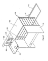
Figure 1 shows a multi user desk apparatus with a number of stored desk capsules inside a desk storage frame, in which one desk capsule is open and ready for work, one desk capsule to the front closed, and one support frame to the right as seen in the Figure is empty for receipt of a stored desk capsule. - The apparatus comprises a generally
rectangular apparatus frame 10, divided into a plurality of chambers or storage compartments each for housing adesk capsule 11. Thedesk capsules 11 are slidably mounted on sliding means in the form of track, rollers or an air cushion arrangement of theapparatus frame 10. Theapparatus frame 10 further comprisesmovable support frames 12 which supportdesk capsules 11 when in a deployed position. As is seen in the embodiment illustrated inFigure 1 , the desk apparatus is provided with three movable support frames 12 in which two are shown in receipt of deployed desk capsules, and one is vacant. The moveable support frames 12 are pivotally attached toapparatus frame 10 through amoveable hinge assembly 13 which allows the frame to be folded against theapparatus frame 10 when it is not required, and also for storage purposes. - As is illustrated in
Figure 1 , moveable support frames 12 are provided with service connecting means 14 so that a user can connect to a power supply, phone socket or the office network. - Towards the front of the multi-user desk apparatus of
Figure 1 is shown a closed desk capsule on the front located moveable support frame. To left and right sides of the desk are mounted modesty orprivacy panels 15. The privacy panels may be removable or pivotally attached to theapparatus frame 10. - The
moveable hinge 13 locates within a vertical channel at an outside edge ofapparatus frame 10 and is adjustable for height. As illustrated inFigures 2 and3 (and further discussed below) a pulley system enables vertical movement of thehinge 13 and consequentlymoveable support frame 12. - In one embodiment, the
support frame 12 is permanently attached throughhinge 13 toapparatus frame 10 and may be provided with support legs. Preferably these are foldably incorporated into the support frame to provide added stability to a desk thus formed. In an alternative embodiment the moveable support frame is demountable and the support legs are preferably fitted with wheels to allow a desk formed from a desk capsule and the moveable support frame to be moved to a location remote from the desk apparatus frame. In further alternative embodiments, separate wheeled support elements are engageable with the underside of a desk capsule and the capsule and wheeled support element are demountable from amoveable support frame 12 for use at a location remote from the desk apparatus frame. - Each
desk capsule 11 comprises a boxed unit with hingedly attachedlid 20. In use, the capsule lid is raised and is lockable in an upright position to prevent the lid falling on a user. The base of thecapsule 11 comprises awork surface 21 which may be adapted to suit a particular expected end use of an individual user. In the embodiment ofFigure 1 , thelid 20 also comprises adesk lamp 22 and notice/pin board 23. Each desk capsule also comprises apost box 24 in a front wall and lid of thecapsule 11 for private memos or mail delivery. - Referring now to
Figures 2 and3 , there is shown a pulley mechanism for independent raising and lowering of each hingedly attachedmoveable support frame 12. -
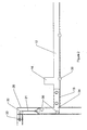
Figure 2 illustrates a partial section throughmoveable support frame 12 showing avertical guide rail 25 of theapparatus frame 10 in which acarriage 34, comprisingmoveable hinge 13 and linkedframe 12, is located.Carriage 34 is supported withinguide rail 25 by bearingwheels 30 and is attached at a top edge to a liftingcable 31. Liftingcable 31 in turn links to a pulley system (Figure 3 ) via adead block 32, located towards the top ofguide rail 25 and mounted uponapparatus frame 10, and a furtherdead block 33, located on the top ofapparatus frame 10. - The
carriage 34 is vertically moveable up and down inside thevertical guide rail 25. As mentioned above, themoveable support frame 12 may be demountable athinge 13, for ease of installation/convenience when not in use or to facilitate demounting of a horizontal support frame having integral support legs and a desk capsule loaded thereon for use remote from themain apparatus frame 10 if required. In alternative embodiments, a wheeled support element is engaged with a desk capsule and the capsule removed frommoveable support frame 12, as described in greater detail below in relation toFigures 5 and 6 . The moveable support frame is fitted withrollers 35 along an inside edge of thesupport frame 12. Therollers 35 may be motorised for automatic operation if required (not shown) or other similar devices to enable easy sliding of the desk capsules on to and off the moveable support frame may also be provided. - Referring to
Figure 3 , liftingcable 31, attached to thecarriage 34 ofFigure 2 , is linked to a motor/gearbox assembly 40 through a pulley/drive mechanism 41 which is located on an upper surface ofapparatus frame 10. Pulley/drive mechanism 41 comprises a rotatable shaft 42 linked at one end through athrust bearing 43 to motor/gearbox assembly 40. Rotatable shaft 42 is at least partially threaded from its opposite end and is screwably engaged with afollower carriage 44. The follower carriage further comprises a pair of follower pulleys 45, through which the respective ends ofcable 31 pass. The ends ofcable 31 are anchored to theapparatus frame 10 at anchor points 50, which are provided with adjustment means for adjusting the cable length (not shown). - In use, motor/
gearbox assembly 40 is operated to rotate shaft 42 and drivefollower carriage 44 by means of the pulley/drive mechanism 41. Depending upon the direction of rotation,follower carriage 44 moves along shaft 42 to raise or lower the height ofdesk carriage 34. In the arrangement of the embodiment shown, when thefollower carriage 44 moves along rotatable shaft 42 towards motor/gearbox assembly 40,cable 31 is drawn so thatdesk carriage 34 is raised relative to the floor surface. Conversely, when thefollower carriage 44 moves away from motor/gearbox assembly 40,cable 31 is let out by the pulley/drive mechanism and thedesk carriage 34 is lowered. -
Position location detectors 51, located on an upper surface of theapparatus frame 10, detect the relative location of the threadedfollower carriage 44 so that the relative height of acapsule 11 located within amoveable support frame 12 can be calibrated and set. By this means, specific height adjustment can be made so that thecarriage 34 can be accurately positioned adjacent aparticular desk capsule 11 bay (antecedent). In alternative embodiments (not shown), position location detectors are located invertical guide rail 25 so that the position ofcarriage 34 can be monitored. - Additionally shown are two further sets of motor/pulley/drive mechanism assemblies to enable independent operation of each moveable support frame.
- In the illustrated embodiments, the three motor/pulley/drive mechanism assemblies are mounted onto a top chassis plate of the
apparatus frame 10, however it will be recognised that in alternative arrangements they could be mounted at any level or on the back or remote from the central storage system. - A system of safety devices and barriers (not shown) may be incorporated to prevent persons entering under the working apparatus during desk capsule changes. These could be fitted with safety interlocks.
- A desk capsule ejection system 52 supported on a
strut 53 of theapparatus frame 10 is illustrated inFigure 4 . The desk capsule ejection system 52 comprises arockable carriage 54, pivotally connected towards its base through aspindle 55, to strut 53. Amotorised jack 60 is pivotally connected to, and located between, one end of therockable carriage 54 andstrut 53, and provides a means torock carriage 54 aboutspindle 55. The desk capsule ejection system 52 also comprises an ejector mechanism comprising areversible motor 61 suitably linked for driving ashaft 62 which is supported onbearings 63. At one end of the reversible motor shaft 62 a bevel gear set 64 drives a front/rearmovement drive wheel 65 supported ondrive wheel shaft 70 which is rotatably mounted in an upper surface ofrockable carriage 54. At a second end, thereversible motor shaft 62 drives a worm gear set 71 which in turn drives the side toside drive wheel 72 supported on side to sidedrive wheel shaft 73, rotatably mounted in an upper surface ofrockable carriage 54. Also shown inFigure 4 is the lower surface of adesk capsule 11 supported on a plurality of non-directional bearings 74 (only one shown for clarity). - To initiate movement of a desk capsule from the central stored location of the
apparatus frame 10 onto amoveable support frame 12 such as shown inFigure 1 , a desk ejection as illustrated inFigure 4 is used. In the embodiment shown, thedesk capsule 11 is supported onnon-directional bearings 74, however in alternative embodiments a low friction surface will be used. To initiate movement themotorised jack 60 is used to engage either drive wheel (65 or 72), as appropriate, with the underside of the desk capsule by suitably moving therockable carnage 54, depending on requirement for front / back movement or side to side movement ofdesk capsule 11. The desk capsule ejection system is used to initiate movement onto the horizontal supports or to dock the desk capsule on return to the central storage unit. Final movement along the horizontal supports is by hand or use of the motorised rollers or other system contained in the horizontal supports. - In use, a user locates their
particular desk capsule 11 and aligns an unusedmoveable support frame 12 adjacent theparticular capsule 11. Alignment of the unusedmoveable support frame 12 will be provided either by controlled motorised means, which may be programmable to return to specific capsule location when used in conjunction with a suitable input means, or by a rotatable height adjustment handle means. The requireddesk capsule 11 is then moved onto themoveable support frame 12 using a desk capsule ejection system as shown inFigure 4 . In alternative constructions, the sides and front of each desk capsule have a handle so that a user can simply pull a required capsule from the apparatus frame without the need for a motorised ejection system. - Once the required
desk capsule 11 has been docked withmoveable support frame 12, themoveable support frame 12 is adjusted to a desired working height and locked in place by a suitable locking means (not shown). The user would then raise thedesk capsule lid 20 to reveal the desk contents as previously left when last used. Raising the lid to its working position could also provide a means of automatically connecting to the office computer and telephone networks, and also a mains power supply system for all normal office functions. - In preferred embodiments, support legs are incorporated in the moveable support frame to give added stability.
- An alternative arrangement is illustrated in
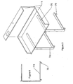
Figures 5 and 6 , in which adesk capsule 11 is supported on a pair ofwheeled support elements 74. Thewheeled support elements 74 are substantially C-shaped and are provided with a pair ofcastors 75 along a bottom edge thereof for moving thedesk capsule 11 to a location remote from theapparatus frame 10, where it is to be used. - The
wheeled support elements 74 are slidably engageable withslots 76, located on the underside of thedesk capsule 11, and lockingly engage to secure them in place whilst in use. - A
desk capsule 11 is removed from theapparatus frame 10 for use in the described alternative arrangement by first selecting a desk capsule using an emptymoveable support frame 12 as described above. Themoveable support frame 12 containing a selecteddesk capsule 11 is then lowered to a position just above normal desk working height, and thewheeled support elements 74 engaged and locked in place on the underside of thedesk capsule 11. Themoveable support frame 12 is subsequently lowered until the desk arrangement is supported oncastors 75 of thewheeled support element 74, and the desk capsule disengaged from themoveable support frame 12. Thedesk capsule 11 on itswheeled support elements 74 is then moved to the required working location. - Replacement and storage of a desk capsule into the
apparatus frame 10 is carried out by the reverse process. - Power supply and office networking connections can be manually connected if required.
- To aid transportation and delivery of a multi-user desk apparatus as described above, the system can be constructed as a modular system. For instance, the top mechanism-containing panel, the front, back and side framework pieces, secrecy panels, moveable desk capsule support frame(s), and the desk capsules could all be supplied as single piece units for construction on-site. This would lead to a reduction in the amount of space required for storage, and also for delivery since the apparatus could be stored in a 'flat-pack' arrangement.
- The desk storage apparatus of the present invention accordingly allows one or more people to work at their 'own' personal desk with their 'own' items on that desk. The desk capsules are easily closed and stored without disturbing the items on the desk surface. The apparatus provides an attractive alternative to traditional hot-desking strategies, which is more flexible, cost effective and makes more efficient use of existing office space. This would permit a business to operate from smaller premises which would result in a reduction in overhead costs whilst allowing the business to maintain a relatively high staff capacity.
- The desk storage apparatus of the present invention additionally lends itself to environments including craft and light assembly work for use in micro-workshops.
Claims (15)
- A multi-user desk apparatus comprising:(a) a frame (10) comprising a plurality of desk capsule receiving chambers;(b) a plurality of desk capsules (11);(c) at least one moveable desk capsule support frame (12).
- A multi-user desk apparatus as claimed in Claim 1 in which the plurality of desk capsules are each slidably mountable within and removable from a respective chamber to the at least one moveable desk capsule support frame.
- A multi-user desk apparatus as claimed in Claim 2 in which each desk capsule is slidably removable from front, rear or side sections of the frame.
- A multi-user desk apparatus as claimed in any of claims 1 to 3 in which the plurality of desk capsules are vertically stackable within the frame.
- A multi-user desk apparatus as claimed in any of claims 1 to 4 in which the at least one moveable desk capsule support frame is adjustable for height by a height adjustment means to facilitate removal of any of the plurality of desk capsules.
- A multi-user desk apparatus as claimed in Claim 5 in which the height adjustment means is motorised, is optionally programmable and further comprises a series of sensors (51) to facilitate precise positioning of a moveable desk capsule support frame operatively-adjacent to a desk capsule-receiving chamber.
- A multi-user desk apparatus as claimed in any of claims 1 to 6 in which the moveable desk capsule support frame is slidably engaged and mounted within vertical channels (25) formed in the apparatus frame.
- A multi-user desk apparatus as claimed in Claim 7 in which the moveable desk capsule support frame is hingedly mounted within the channel of the apparatus frame to allow the support frame to be folded against the apparatus frame for storage or when not in use.
- A multi-user desk apparatus as claimed in any of claims 7 to 8 in which the moveable desk capsule support frame further comprises between one and four support legs, wherein the legs are optionally adjustable for height.
- A multi-user desk apparatus as claimed in Claim 9 in which the moveable desk capsule support frame is demountable from the hinge attachment wherein the support legs optionally comprise wheels.
- A multi-user desk apparatus as claimed in Claim 1 in which two moveable desk capsule support frames are provided for simultaneous use.
- A multi-user desk apparatus as claimed in any one of claims 1 to 6 in which a desk capsule is demountable from the moveable desk capsule support frame and engageable with at least one wheeled support element (74).
- A multi-user desk apparatus as claimed in Claim 12 in which the desk capsule further comprises slots (76) or channels in an underside thereof for engagement with the at least one wheeled support element, and in which the at least one wheeled support element is lockingly engageable with a desk capsule.
- A multi-user desk apparatus as claimed in any preceding claim in which the support frame further comprises electrical service means (14) comprising an electrical power supply and computer network and telephone connection means.
- A multi-user desk apparatus as claimed in any preceding claim in modular form comprising a top mechanism-containing panel, front, back and side framework pieces, secrecy panels, at least one moveable desk capsule support element, and a plurality of desk capsules.
Applications Claiming Priority (2)
| Application Number | Priority Date | Filing Date | Title |
|---|---|---|---|
| GB0520161A GB2430869B (en) | 2005-10-05 | 2005-10-05 | Multi-user desk system |
| PCT/GB2006/050313 WO2007039770A1 (en) | 2005-10-05 | 2006-10-04 | Multi-user desk system |
Publications (2)
| Publication Number | Publication Date |
|---|---|
| EP1945062A1 EP1945062A1 (en) | 2008-07-23 |
| EP1945062B1 true EP1945062B1 (en) | 2010-12-08 |
Family
ID=35395236
Family Applications (1)
| Application Number | Title | Priority Date | Filing Date |
|---|---|---|---|
| EP06779656A Not-in-force EP1945062B1 (en) | 2005-10-05 | 2006-10-04 | Multi-user desk system |
Country Status (5)
| Country | Link |
|---|---|
| EP (1) | EP1945062B1 (en) |
| AT (1) | ATE490707T1 (en) |
| DE (1) | DE602006018774D1 (en) |
| GB (1) | GB2430869B (en) |
| WO (1) | WO2007039770A1 (en) |
Cited By (1)
| Publication number | Priority date | Publication date | Assignee | Title |
|---|---|---|---|---|
| USD743189S1 (en) | 2013-03-15 | 2015-11-17 | Herman Miller, Inc. | Workstation |
Families Citing this family (4)
| Publication number | Priority date | Publication date | Assignee | Title |
|---|---|---|---|---|
| CN103622319B (en) * | 2013-12-06 | 2016-05-25 | 志邦厨柜股份有限公司 | A concealed kitchen cabinet dinner table |
| EP3565933A4 (en) | 2017-05-19 | 2021-03-10 | DIRTT Environmental Solutions, Ltd. | Systems and methods for selectively positioning wall-mounted devices |
| CN108030239A (en) * | 2017-12-27 | 2018-05-15 | 林建民 | A kind of desk |
| US11957242B2 (en) | 2019-03-20 | 2024-04-16 | Dirtt Environmental Solutions Ltd. | Height adjusting and leveling worksurface cantilever |
Family Cites Families (14)
| Publication number | Priority date | Publication date | Assignee | Title |
|---|---|---|---|---|
| GB105438A (en) * | ||||
| GB1087973A (en) * | 1964-11-05 | 1967-10-18 | Pascual Jose Maria Oscoz Sanch | Improvements in folding table assemblies |
| DE2403442A1 (en) * | 1974-01-25 | 1975-07-31 | Klaus Kroner | Writing-case with storage for implements - cover forms writing surface when folded out at right angles |
| GB2130175B (en) * | 1982-11-12 | 1986-04-03 | Stanley Alfred Edwards | Elevating mechanism |
| AT381857B (en) * | 1985-02-05 | 1986-12-10 | Kotschy Peter Dr | PREFERABLY DRIVELY TRAINED FURNITURE FOR A DENTAL PRACTICE |
| WO1991015133A1 (en) * | 1990-03-30 | 1991-10-17 | John Victor Hawkins | Working desk case |
| US5242056A (en) * | 1992-03-09 | 1993-09-07 | Farrukh Zia | Portable office |
| DE4241132C2 (en) * | 1992-12-07 | 1994-11-17 | Peter Dr Brasse | Work furniture with movable worktops |
| CN1149242A (en) * | 1994-04-06 | 1997-05-07 | 李恩玉 | Apparatus for setting-furniture in variable elevated positions |
| US5647484A (en) * | 1996-05-31 | 1997-07-15 | Fleming; Daniel J. | Laptop computer encasement device adapted for printer |
| GB9612735D0 (en) * | 1996-06-18 | 1996-08-21 | Wozencroft Mark D | Furniture unit |
| US5666265A (en) * | 1996-06-21 | 1997-09-09 | Lutz; Ron E | Portable workstation housing |
| US6530475B1 (en) * | 2000-06-07 | 2003-03-11 | Joseph J. Penney | Portable office |
| DE20205145U1 (en) * | 2002-04-03 | 2003-01-02 | Akcam Alev | Compact work station, has multitude of functional units to be folded or pulled into position if required |
-
2005
- 2005-10-05 GB GB0520161A patent/GB2430869B/en active Active
-
2006
- 2006-10-04 WO PCT/GB2006/050313 patent/WO2007039770A1/en active Application Filing
- 2006-10-04 AT AT06779656T patent/ATE490707T1/en not_active IP Right Cessation
- 2006-10-04 DE DE602006018774T patent/DE602006018774D1/en active Active
- 2006-10-04 EP EP06779656A patent/EP1945062B1/en not_active Not-in-force
Cited By (1)
| Publication number | Priority date | Publication date | Assignee | Title |
|---|---|---|---|---|
| USD743189S1 (en) | 2013-03-15 | 2015-11-17 | Herman Miller, Inc. | Workstation |
Also Published As
| Publication number | Publication date |
|---|---|
| WO2007039770A1 (en) | 2007-04-12 |
| GB2430869B (en) | 2009-07-29 |
| WO2007039770B1 (en) | 2007-05-31 |
| GB0520161D0 (en) | 2005-11-09 |
| GB2430869A (en) | 2007-04-11 |
| DE602006018774D1 (en) | 2011-01-20 |
| EP1945062A1 (en) | 2008-07-23 |
| ATE490707T1 (en) | 2010-12-15 |
Similar Documents
| Publication | Publication Date | Title |
|---|---|---|
| EP3413751B1 (en) | Combination foldable and adjustable workstation | |
| US5584546A (en) | Transportable office work station | |
| US8322802B2 (en) | Office furniture system | |
| US20110089304A1 (en) | Lift System | |
| US8424983B1 (en) | Motorized upper and lower storage shelves | |
| US7032523B2 (en) | Workstation with a moveable apparatus | |
| EP1945062B1 (en) | Multi-user desk system | |
| CN117257048A (en) | Height adjustable device with hidden lifting mechanism | |
| US20070181044A1 (en) | Utility distribution system | |
| US8556355B2 (en) | Method and apparatus for optimizing storage space | |
| GB2309163A (en) | Table with an elevating panel, an elevating table, and a combination thereof | |
| US20070126319A1 (en) | Laboratory cart with removable/slidable storage units | |
| US5375514A (en) | Adjustable height table support mechanism | |
| CN211622744U (en) | Folding private warehouse | |
| CN214760066U (en) | Storage type office table and chair | |
| US7481502B2 (en) | Office desk front panel and hardware adapted for 90-degree rotation from vertical storage position into a horizontal workspace position | |
| CN110700637A (en) | Folding private warehouse | |
| US20050006331A1 (en) | Revolving slide | |
| EP0447961A2 (en) | Furniture assemblage | |
| JP3216811U (en) | Ergonomic storage | |
| US20180084929A1 (en) | Modular counter system and method | |
| GB2391022A (en) | Transportable buildings which can interlink | |
| EP1689269B1 (en) | Method for retracting a bed and device for carrying out said method | |
| CN209563838U (en) | A kind of embedded multiple-degree-of-freedom seat handrail folding table of bilateral | |
| DE102018006388A1 (en) | Operating, work and lecture desk |
Legal Events
| Date | Code | Title | Description |
|---|---|---|---|
| PUAI | Public reference made under article 153(3) epc to a published international application that has entered the european phase |
Free format text: ORIGINAL CODE: 0009012 |
|
| 17P | Request for examination filed |
Effective date: 20080501 |
|
| AK | Designated contracting states |
Kind code of ref document: A1 Designated state(s): AT BE BG CH CY CZ DE DK EE ES FI FR GB GR HU IE IS IT LI LT LU LV MC NL PL PT RO SE SI SK TR |
|
| DAX | Request for extension of the european patent (deleted) | ||
| REG | Reference to a national code |
Ref country code: HK Ref legal event code: DE Ref document number: 1122710 Country of ref document: HK |
|
| GRAP | Despatch of communication of intention to grant a patent |
Free format text: ORIGINAL CODE: EPIDOSNIGR1 |
|
| GRAS | Grant fee paid |
Free format text: ORIGINAL CODE: EPIDOSNIGR3 |
|
| GRAA | (expected) grant |
Free format text: ORIGINAL CODE: 0009210 |
|
| AK | Designated contracting states |
Kind code of ref document: B1 Designated state(s): AT BE BG CH CY CZ DE DK EE ES FI FR GB GR HU IE IS IT LI LT LU LV MC NL PL PT RO SE SI SK TR |
|
| REG | Reference to a national code |
Ref country code: GB Ref legal event code: FG4D |
|
| REG | Reference to a national code |
Ref country code: CH Ref legal event code: EP |
|
| REG | Reference to a national code |
Ref country code: IE Ref legal event code: FG4D |
|
| REF | Corresponds to: |
Ref document number: 602006018774 Country of ref document: DE Date of ref document: 20110120 Kind code of ref document: P |
|
| REG | Reference to a national code |
Ref country code: NL Ref legal event code: VDEP Effective date: 20101208 |
|
| PG25 | Lapsed in a contracting state [announced via postgrant information from national office to epo] |
Ref country code: LT Free format text: LAPSE BECAUSE OF FAILURE TO SUBMIT A TRANSLATION OF THE DESCRIPTION OR TO PAY THE FEE WITHIN THE PRESCRIBED TIME-LIMIT Effective date: 20101208 |
|
| LTIE | Lt: invalidation of european patent or patent extension |
Effective date: 20101208 |
|
| PG25 | Lapsed in a contracting state [announced via postgrant information from national office to epo] |
Ref country code: CY Free format text: LAPSE BECAUSE OF FAILURE TO SUBMIT A TRANSLATION OF THE DESCRIPTION OR TO PAY THE FEE WITHIN THE PRESCRIBED TIME-LIMIT Effective date: 20101208 Ref country code: AT Free format text: LAPSE BECAUSE OF FAILURE TO SUBMIT A TRANSLATION OF THE DESCRIPTION OR TO PAY THE FEE WITHIN THE PRESCRIBED TIME-LIMIT Effective date: 20101208 Ref country code: LV Free format text: LAPSE BECAUSE OF FAILURE TO SUBMIT A TRANSLATION OF THE DESCRIPTION OR TO PAY THE FEE WITHIN THE PRESCRIBED TIME-LIMIT Effective date: 20101208 Ref country code: BG Free format text: LAPSE BECAUSE OF FAILURE TO SUBMIT A TRANSLATION OF THE DESCRIPTION OR TO PAY THE FEE WITHIN THE PRESCRIBED TIME-LIMIT Effective date: 20110308 Ref country code: SI Free format text: LAPSE BECAUSE OF FAILURE TO SUBMIT A TRANSLATION OF THE DESCRIPTION OR TO PAY THE FEE WITHIN THE PRESCRIBED TIME-LIMIT Effective date: 20101208 Ref country code: FI Free format text: LAPSE BECAUSE OF FAILURE TO SUBMIT A TRANSLATION OF THE DESCRIPTION OR TO PAY THE FEE WITHIN THE PRESCRIBED TIME-LIMIT Effective date: 20101208 Ref country code: SE Free format text: LAPSE BECAUSE OF FAILURE TO SUBMIT A TRANSLATION OF THE DESCRIPTION OR TO PAY THE FEE WITHIN THE PRESCRIBED TIME-LIMIT Effective date: 20101208 Ref country code: NL Free format text: LAPSE BECAUSE OF FAILURE TO SUBMIT A TRANSLATION OF THE DESCRIPTION OR TO PAY THE FEE WITHIN THE PRESCRIBED TIME-LIMIT Effective date: 20101208 |
|
| PG25 | Lapsed in a contracting state [announced via postgrant information from national office to epo] |
Ref country code: EE Free format text: LAPSE BECAUSE OF FAILURE TO SUBMIT A TRANSLATION OF THE DESCRIPTION OR TO PAY THE FEE WITHIN THE PRESCRIBED TIME-LIMIT Effective date: 20101208 Ref country code: BE Free format text: LAPSE BECAUSE OF FAILURE TO SUBMIT A TRANSLATION OF THE DESCRIPTION OR TO PAY THE FEE WITHIN THE PRESCRIBED TIME-LIMIT Effective date: 20101208 Ref country code: IS Free format text: LAPSE BECAUSE OF FAILURE TO SUBMIT A TRANSLATION OF THE DESCRIPTION OR TO PAY THE FEE WITHIN THE PRESCRIBED TIME-LIMIT Effective date: 20110408 Ref country code: GR Free format text: LAPSE BECAUSE OF FAILURE TO SUBMIT A TRANSLATION OF THE DESCRIPTION OR TO PAY THE FEE WITHIN THE PRESCRIBED TIME-LIMIT Effective date: 20110309 Ref country code: CZ Free format text: LAPSE BECAUSE OF FAILURE TO SUBMIT A TRANSLATION OF THE DESCRIPTION OR TO PAY THE FEE WITHIN THE PRESCRIBED TIME-LIMIT Effective date: 20101208 Ref country code: PT Free format text: LAPSE BECAUSE OF FAILURE TO SUBMIT A TRANSLATION OF THE DESCRIPTION OR TO PAY THE FEE WITHIN THE PRESCRIBED TIME-LIMIT Effective date: 20110408 Ref country code: ES Free format text: LAPSE BECAUSE OF FAILURE TO SUBMIT A TRANSLATION OF THE DESCRIPTION OR TO PAY THE FEE WITHIN THE PRESCRIBED TIME-LIMIT Effective date: 20110319 |
|
| PG25 | Lapsed in a contracting state [announced via postgrant information from national office to epo] |
Ref country code: SK Free format text: LAPSE BECAUSE OF FAILURE TO SUBMIT A TRANSLATION OF THE DESCRIPTION OR TO PAY THE FEE WITHIN THE PRESCRIBED TIME-LIMIT Effective date: 20101208 Ref country code: PL Free format text: LAPSE BECAUSE OF FAILURE TO SUBMIT A TRANSLATION OF THE DESCRIPTION OR TO PAY THE FEE WITHIN THE PRESCRIBED TIME-LIMIT Effective date: 20101208 Ref country code: RO Free format text: LAPSE BECAUSE OF FAILURE TO SUBMIT A TRANSLATION OF THE DESCRIPTION OR TO PAY THE FEE WITHIN THE PRESCRIBED TIME-LIMIT Effective date: 20101208 |
|
| PLBE | No opposition filed within time limit |
Free format text: ORIGINAL CODE: 0009261 |
|
| STAA | Information on the status of an ep patent application or granted ep patent |
Free format text: STATUS: NO OPPOSITION FILED WITHIN TIME LIMIT |
|
| PG25 | Lapsed in a contracting state [announced via postgrant information from national office to epo] |
Ref country code: DK Free format text: LAPSE BECAUSE OF FAILURE TO SUBMIT A TRANSLATION OF THE DESCRIPTION OR TO PAY THE FEE WITHIN THE PRESCRIBED TIME-LIMIT Effective date: 20101208 |
|
| 26N | No opposition filed |
Effective date: 20110909 |
|
| PG25 | Lapsed in a contracting state [announced via postgrant information from national office to epo] |
Ref country code: IT Free format text: LAPSE BECAUSE OF FAILURE TO SUBMIT A TRANSLATION OF THE DESCRIPTION OR TO PAY THE FEE WITHIN THE PRESCRIBED TIME-LIMIT Effective date: 20101208 |
|
| REG | Reference to a national code |
Ref country code: DE Ref legal event code: R097 Ref document number: 602006018774 Country of ref document: DE Effective date: 20110909 |
|
| PG25 | Lapsed in a contracting state [announced via postgrant information from national office to epo] |
Ref country code: MC Free format text: LAPSE BECAUSE OF NON-PAYMENT OF DUE FEES Effective date: 20111031 |
|
| REG | Reference to a national code |
Ref country code: CH Ref legal event code: PL |
|
| GBPC | Gb: european patent ceased through non-payment of renewal fee |
Effective date: 20111004 |
|
| REG | Reference to a national code |
Ref country code: FR Ref legal event code: ST Effective date: 20120629 |
|
| PG25 | Lapsed in a contracting state [announced via postgrant information from national office to epo] |
Ref country code: DE Free format text: LAPSE BECAUSE OF NON-PAYMENT OF DUE FEES Effective date: 20120501 Ref country code: LI Free format text: LAPSE BECAUSE OF NON-PAYMENT OF DUE FEES Effective date: 20111031 Ref country code: CH Free format text: LAPSE BECAUSE OF NON-PAYMENT OF DUE FEES Effective date: 20111031 |
|
| REG | Reference to a national code |
Ref country code: IE Ref legal event code: MM4A |
|
| REG | Reference to a national code |
Ref country code: DE Ref legal event code: R119 Ref document number: 602006018774 Country of ref document: DE Effective date: 20120501 |
|
| PG25 | Lapsed in a contracting state [announced via postgrant information from national office to epo] |
Ref country code: FR Free format text: LAPSE BECAUSE OF NON-PAYMENT OF DUE FEES Effective date: 20111102 Ref country code: GB Free format text: LAPSE BECAUSE OF NON-PAYMENT OF DUE FEES Effective date: 20111004 |
|
| PG25 | Lapsed in a contracting state [announced via postgrant information from national office to epo] |
Ref country code: IE Free format text: LAPSE BECAUSE OF NON-PAYMENT OF DUE FEES Effective date: 20111004 |
|
| PG25 | Lapsed in a contracting state [announced via postgrant information from national office to epo] |
Ref country code: LU Free format text: LAPSE BECAUSE OF NON-PAYMENT OF DUE FEES Effective date: 20111004 |
|
| PG25 | Lapsed in a contracting state [announced via postgrant information from national office to epo] |
Ref country code: TR Free format text: LAPSE BECAUSE OF FAILURE TO SUBMIT A TRANSLATION OF THE DESCRIPTION OR TO PAY THE FEE WITHIN THE PRESCRIBED TIME-LIMIT Effective date: 20101208 |
|
| PG25 | Lapsed in a contracting state [announced via postgrant information from national office to epo] |
Ref country code: HU Free format text: LAPSE BECAUSE OF FAILURE TO SUBMIT A TRANSLATION OF THE DESCRIPTION OR TO PAY THE FEE WITHIN THE PRESCRIBED TIME-LIMIT Effective date: 20101208 |
|
| REG | Reference to a national code |
Ref country code: HK Ref legal event code: WD Ref document number: 1122710 Country of ref document: HK |