EP1945008B1 - Light sensor for a pre-switching device for operating a gas discharge light - Google Patents
Light sensor for a pre-switching device for operating a gas discharge light Download PDFInfo
- Publication number
- EP1945008B1 EP1945008B1 EP08155561.7A EP08155561A EP1945008B1 EP 1945008 B1 EP1945008 B1 EP 1945008B1 EP 08155561 A EP08155561 A EP 08155561A EP 1945008 B1 EP1945008 B1 EP 1945008B1
- Authority
- EP
- European Patent Office
- Prior art keywords
- lamp
- gas discharge
- discharge lamp
- circuit
- potential
- Prior art date
- Legal status (The legal status is an assumption and is not a legal conclusion. Google has not performed a legal analysis and makes no representation as to the accuracy of the status listed.)
- Expired - Lifetime
Links
- 239000003990 capacitor Substances 0.000 claims abstract description 25
- 230000008878 coupling Effects 0.000 claims abstract description 23
- 238000010168 coupling process Methods 0.000 claims abstract description 23
- 238000005859 coupling reaction Methods 0.000 claims abstract description 23
- 238000011156 evaluation Methods 0.000 claims abstract description 11
- 238000000034 method Methods 0.000 claims abstract description 7
- 238000010438 heat treatment Methods 0.000 claims description 50
- 238000004804 winding Methods 0.000 claims description 8
- 238000005259 measurement Methods 0.000 claims description 5
- 238000001514 detection method Methods 0.000 abstract description 10
- 230000007257 malfunction Effects 0.000 abstract description 6
- 230000001939 inductive effect Effects 0.000 description 6
- 230000002950 deficient Effects 0.000 description 2
- 238000012544 monitoring process Methods 0.000 description 2
- 230000005540 biological transmission Effects 0.000 description 1
- 238000006243 chemical reaction Methods 0.000 description 1
- 230000001419 dependent effect Effects 0.000 description 1
- 238000005516 engineering process Methods 0.000 description 1
- 230000000977 initiatory effect Effects 0.000 description 1
- 238000003780 insertion Methods 0.000 description 1
- 230000037431 insertion Effects 0.000 description 1
- 230000010355 oscillation Effects 0.000 description 1
- 238000010079 rubber tapping Methods 0.000 description 1
Images

Classifications
-
- H—ELECTRICITY
- H05—ELECTRIC TECHNIQUES NOT OTHERWISE PROVIDED FOR
- H05B—ELECTRIC HEATING; ELECTRIC LIGHT SOURCES NOT OTHERWISE PROVIDED FOR; CIRCUIT ARRANGEMENTS FOR ELECTRIC LIGHT SOURCES, IN GENERAL
- H05B41/00—Circuit arrangements or apparatus for igniting or operating discharge lamps
- H05B41/14—Circuit arrangements
- H05B41/26—Circuit arrangements in which the lamp is fed by power derived from dc by means of a converter, e.g. by high-voltage dc
- H05B41/28—Circuit arrangements in which the lamp is fed by power derived from dc by means of a converter, e.g. by high-voltage dc using static converters
- H05B41/295—Circuit arrangements in which the lamp is fed by power derived from dc by means of a converter, e.g. by high-voltage dc using static converters with semiconductor devices and specially adapted for lamps with preheating electrodes, e.g. for fluorescent lamps
- H05B41/298—Arrangements for protecting lamps or circuits against abnormal operating conditions
- H05B41/2981—Arrangements for protecting lamps or circuits against abnormal operating conditions for protecting the circuit against abnormal operating conditions
- H05B41/2985—Arrangements for protecting lamps or circuits against abnormal operating conditions for protecting the circuit against abnormal operating conditions against abnormal lamp operating conditions
-
- H—ELECTRICITY
- H05—ELECTRIC TECHNIQUES NOT OTHERWISE PROVIDED FOR
- H05B—ELECTRIC HEATING; ELECTRIC LIGHT SOURCES NOT OTHERWISE PROVIDED FOR; CIRCUIT ARRANGEMENTS FOR ELECTRIC LIGHT SOURCES, IN GENERAL
- H05B41/00—Circuit arrangements or apparatus for igniting or operating discharge lamps
- H05B41/14—Circuit arrangements
- H05B41/26—Circuit arrangements in which the lamp is fed by power derived from dc by means of a converter, e.g. by high-voltage dc
- H05B41/28—Circuit arrangements in which the lamp is fed by power derived from dc by means of a converter, e.g. by high-voltage dc using static converters
- H05B41/282—Circuit arrangements in which the lamp is fed by power derived from dc by means of a converter, e.g. by high-voltage dc using static converters with semiconductor devices
- H05B41/285—Arrangements for protecting lamps or circuits against abnormal operating conditions
- H05B41/2851—Arrangements for protecting lamps or circuits against abnormal operating conditions for protecting the circuit against abnormal operating conditions
- H05B41/2855—Arrangements for protecting lamps or circuits against abnormal operating conditions for protecting the circuit against abnormal operating conditions against abnormal lamp operating conditions
Definitions
- the invention relates to a ballast for at least one gas discharge lamp.
- the lamp electrodes are preheated before the ignition voltage is applied between them. It has been shown that the life of the lamps can be extended to a considerable extent by this measure.
- the gas discharge lamp is usually operated on a series resonant circuit, wherein the resonant circuit capacitor is generally parallel to the discharge path of the gas discharge lamp.
- the electrodes of the lamp are designed as heating coils, through which the current of the resonant circuit flows when the lamp is not lit.
- the frequency is changed relative to the resonance frequency of the series resonant circuit such that the voltage across the resonant capacitor and thus across the gas discharge lamp does not cause ignition of the gas discharge lamp.
- a substantially constant current flows through the lamp electrodes designed as helices, so that they are preheated.
- the frequency is set in the vicinity of the resonant frequency of the resonant circuit, whereby the voltage across the resonant capacitor is increased so that the gas discharge lamp finally ignites.
- the ballast should additionally have a function monitoring the status of the lamp in order to detect any malfunctions and to be able to initiate corresponding measures. These measures may include, for example, the shutdown of the high voltage part.
- a malfunction may occur, for example, if one of the two coils or both are defective, or if the lamp has been completely removed or not (correctly) inserted into the sockets of the lamp.
- a ballast for the operation of gas discharge lamps which contains a controlled inverter, which operates at a frequency above the mains frequency.
- a monitoring circuit which is connected in parallel with the gas discharge lamp, both the supply voltage for the inverter and the voltage occurring at the lamp filaments are monitored.
- the inverter is thereby to be protected against overload due to a too high supply voltage or in the absence or failure of the fluorescent lamp.
- the publication EP 0 707 437 A2 describes a circuit arrangement for operating one or more low-pressure discharge lamps.
- the circuit arrangement includes an inverter and a drive device for the inverter and a DC path which connects the drive device of the inverter with an electrical voltage source and in which the electrodes of the low-pressure charged lamps to be operated are integrated.
- the DC path ensures that the drive device starts the inverter for the first time.
- the lamp electrodes are integrated in the DC path, so that in the case of a defective lamp electrode, the DC path is interrupted. This prevents a renewed oscillation of the inverter when the supply voltage is switched on.
- the publication US 5,883,473 describes an operating device having an AC-to-DC converter, an inverter, a high voltage detection circuit 500, and a no-load detection circuit 600.
- the operating device stops switching the inverter in response to lamp failures.
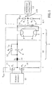
- Fig. 3 schematically shows a section of a ballast, which is designed on the one hand for detecting a lamp failure (coil breakage, non-insertion or removal of the lamp, etc.) and on the other hand for detecting the lamp voltage.
- a lamp failure coil breakage, non-insertion or removal of the lamp, etc.
- a lamp voltage It is denoted by the reference numeral 1 in the FIGS. 1 to 3 schematically an inverter with its two alternately clocked switches (power transistors) 17 and 18 referred to.
- a load circuit 3 is connected, which has a series resonant circuit 22, consisting of a resonance inductor 16 (L R ) and a resonant capacitor 5 (C R ) .
- a coupling capacitor 2 C K
- the discharge path of the lamp 4 is connected in parallel with the resonance capacitor 5.
- the heating coils 8 and 9 of the gas discharge lamp 4 can be seen.
- a measuring resistor 26 (R) is connected, through which the lamp current and the Helical current flows.
- a measuring signal 10a (S1) can be tapped which shows whether a heating current can flow through the coils 8 and 9 in the unfired condition of the lamp and if thus a lamp 4 with proper heating coils 8 and 9 is inserted in the provided sockets.
- a voltage divider 7 is additionally connected in parallel to the gas discharge lamp 4 on the side of the coupling capacitor 2 ( C K ) of the load circuit 3.
- This voltage divider 7 has two resistors 14 and 15 ( R 1 and R 2 ) , which are connected in series.
- a signal 10b (S2) can be tapped, which is representative of the voltage applied across the discharge path of the gas discharge lamp 4 voltage.
- the sensor circuit has a voltage divider which, on the one hand, is connected to the "upper" potential-carrying filament of the lamp and, on the other hand, to ground.
- the sensor circuit 6 allows the tapping of a sensor signal (S2) for detecting a lamp failure or for detecting the lamp voltage.
- S2 sensor signal
- a high-resistance resistor R K may be connected in parallel to easily form a DC branch.
- the sensor circuit may be integrated in an ASIC.
- the heating power can be capacitively or inductively coupled into at least one filament of the gas discharge lamp.
- a method for detecting the lamp voltage and for detecting a lamp failure in a ballast for gas discharge lamps according to claim 7 is provided according to the invention.
- the filament current is monitored and during normal operation the lamp current is monitored.
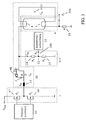
- Fig. 1 schematically an embodiment of the present invention is shown.
- the ballast according to the invention has an inverter 1 with two series-connected, connected to a DC voltage source U bus and alternately clocked transistor switches 17 and 18 ( T 1 and T 2 ) on.
- the switching can be effected by a control unit 23, which can be realized as an integrated circuit (IC) and in particular in an ASIC.
- a load circuit 3 is connected, which has a series resonant circuit 22 and the lamp 4.
- the series resonant circuit 22 consists of a resonance inductor 16 ( L R ) and a resonant capacitor 5 ( C R ).
- the discharge path of the gas discharge lamp 4 between the two heating coils 8 and 9 is, as known, connected in parallel with the resonance capacitor 5 (C R ) .
- a high-resistance resistor 12 ( R K ) is connected, so that bypassing the coupling capacitor 2 ( C K ) a low DC current I Dc through the upper heating coil 8 and a voltage divider explained later in detail. 7 can flow.
- a measurement signal 10b is generated (Sensor signal S2) tapped, which after an analog-to-digital conversion of a (digital) evaluation circuit 13 can be supplied.
- This evaluation circuit 13 can also be implemented as an integrated circuit.
- the voltage divider 7 together with the signal tap 11 thus represents a sensor circuit 6 for detecting a lamp failure as well as for detecting the lamp voltage.
- the evaluation circuit 13 can detect the following luminous states depending on the value of the sensor signal 10b (S2):
- the high-resistance resistor 12 (R K ) in the parallel branch of the coupling capacitor 2 (C K ) further has the advantage that it so-called "Walmen", ie alternately bright and dark sections in the gas discharge lamp 4, by providing a can at least greatly reduce certain DC component.
- Fig. 2 shows a further embodiment of the present invention.
- the coupling of the heating power takes place in the heating coils 8 and 9 inductively via the two coils 19 and 20 ( L h 1 and L h 2 ) of a transformer. While a capacitive coupling of the heating power is usually preferred for non-dimmed devices, the dimmed devices, the inductive form of Schumacherseinkopplung is preferred.
- the primary winding 21 ( L h 3 ) of a separate transformer can be used as a primary winding for the inductive heating power transmission.
- the resonance inductance 16 ( L R ) is also shown schematically that the primary winding 21 ( L h 3 ) of a separate transformer can be used as a primary winding for the inductive heating power transmission.
- the resonance inductance 16 ( L R ) is also shown schematically as a primary winding for the inductive coupling of the heating power into the heating coils 8 and 9 of the gas discharge lamp 4.
- any type of coupling of the heating power in the heating coils 8 and 9 can be applied.
- Inductance L h2 (implemented as a primary winding of a heating transformer Tr 2 ) for inductive coupling of the heating power in the second (lower) heating coil 9 of the gas discharge lamp.
- Inductance L h3 (realized as a primary winding of a heating transformer Tr 3 ) for inductive coupling of the heating power in the heating coils of the gas discharge lamp.
- 4 22 Series resonant circuit as part of the load circuit 3
- Control unit (implemented as IC or ASIC) for driving the two realized as a self-locking n-channel MOSFETs T 1 and T 2 transistor switch 17 and 18th 24 Coupling capacitor C h 1 in Einkoppelzweig the first (upper) heating coil 8 of the gas discharge lamp.
- 4 25 Coupling capacitor C h2 in Einkoppelzweig the second (lower) heating coil 9 of the gas discharge lamp.
- 4 26 Measuring resistor R , connected in series with the second (lower) heating coil of the gas discharge lamp.
Abstract
Description
Die Erfindung betrifft ein Vorschaltgerät für mindestens eine Gasentladungslampe.The invention relates to a ballast for at least one gas discharge lamp.
Üblicherweise werden heutzutage bei hochwertigen Vorschaltgeräten für Gasentladungslampen die Lampenelektroden vorgeheizt, bevor die Zündspannung zwischen diesen angelegt wird. Es hat sich gezeigt, dass durch diese Maßnahme die Lebensdauer der Lampen in erheblichem Maße verlängert werden kann.Typically, nowadays in high quality ballasts for gas discharge lamps, the lamp electrodes are preheated before the ignition voltage is applied between them. It has been shown that the life of the lamps can be extended to a considerable extent by this measure.
Wie beispielsweise in
Das Vorschaltgerät sollte neben der Hauptfunktion der Initiierung, Aufrechterhaltung und Abschaltung der Gasentladung zusätzlich eine den Zustand der Lampe überwachende Funktion aufweisen, um eventuelle Betriebsstörungen erfassen und dementsprechende Maßnahmen einleiten zu können. Diese Maßnahmen können beispielsweise die Abschaltung des Hochspannungsteils beinhalten.In addition to the main function of initiating, maintaining and switching off the gas discharge, the ballast should additionally have a function monitoring the status of the lamp in order to detect any malfunctions and to be able to initiate corresponding measures. These measures may include, for example, the shutdown of the high voltage part.
Eine Betriebsstörung kann beispielsweise dann vorliegen, wenn eine der beiden Wendeln oder auch beide defekt sind, oder wenn die Lampe vollständig entfernt bzw. nicht (korrekt) in die Fassungen der Leuchte eingesetzt wurde.A malfunction may occur, for example, if one of the two coils or both are defective, or if the lamp has been completely removed or not (correctly) inserted into the sockets of the lamp.
Aus
In der Druckschrift
Die Druckschrift
Die Druckschrift
Eine weitere Anforderung an moderne Vorschaltgeräte ist die Erfassung der über der Entladungsstrecke der Gasentladungslampe anliegenden Spannung.Another requirement for modern ballasts is the detection of the voltage applied across the discharge path of the gas discharge lamp.
Weiterhin sind die Heizwendeln 8 und 9 der Gasentladungslampe 4 ersichtlich. In Serie zu der unteren Heizwendel 9, d.h. zwischen der Lampe 4 und dem Masseknoten ist ein Messwiderstand 26 (R) geschaltet, durch den der Lampenstrom und der Wendelstrom fließt. Mittels der somit an dem Messwiderstand 26 (R) abfallenden Spannung kann ein Messsignal 10a (S1) abgegriffen werden, das wiedergibt, ob im ungezündeten Zustand der Lampe ein Heizstrom durch die Wendeln 8 und 9 fließen kann und ob somit eine Lampe 4 mit ordnungsgemäßen Heizwendeln 8 und 9 in die dafür vorgesehenen Fassungen eingesetzt ist.Furthermore, the
Zur Erfassung der Lampenspannung ist zusätzlich auf der Seite des Koppelkondensators 2 (CK ) des Lastkreises 3 ein Spannungsteiler 7 parallel zur Gasentladungslampe 4 geschaltet. Dieser Spannungsteiler 7 weist zwei Widerstände 14 und 15 (R 1 bzw. R2) auf, die in Serie geschaltet sind. Somit kann an dem Schaltungsknoten 11 zwischen den beiden Widerständen 14 und 15 ein Signal 10b (S2) abgegriffen werden, das für die über der Entladungsstrecke der Gasentladungslampe 4 anliegende Spannung repräsentativ ist.For detecting the lamp voltage, a voltage divider 7 is additionally connected in parallel to the
Festzuhalten ist somit, dass bei einer derartigen Schaltung für die Erfassung der Lampenspannung sowie für die Erkennung einer Betriebsstörung der Lampe 4 je eine separat vorgesehene Schaltung vorgesehen werden muss. Dementsprechend müssen auch zwei Signale S1 und S2 verwertet werden.It should be noted that in such a circuit for the detection of the lamp voltage as well as for the detection of a malfunction of the
Angesichts der oben genannten Anforderungen an moderne elektronische Vorschaltgeräte ist es Aufgabe der vorliegenden Erfindung, eine Technologie bereitzustellen, die die Erfassung der an einer Gasentladungslampe in Betrieb anliegenden Spannung sowie das Erkennen einer Lampenstörung (fehlende Lampe etc.) in einfacher Weise ermöglicht.In view of the above requirements for modern electronic ballasts, it is an object of the present invention to provide a technology that allows the detection of voltage applied to a gas discharge lamp in operation voltage and the detection of a lamp failure (missing lamp, etc.) in a simple manner.
Insbesondere sollte für die Erfassung der Lampenspannung sowie die Erkennung einer Betriebsstörung der Lampe ein einziges Signal genügen.In particular, a single signal should suffice for the detection of the lamp voltage as well as the detection of a malfunction of the lamp.
Diese Aufgabe wird erfindungsgemäß durch die Merkmale des unabhängigen Anspruchs gelöst. Die abhängigen Ansprüche bilden den zentralen Gedanken der Erfindung in besonders vorteilhafter Weise weiter.This object is achieved by the features of the independent claim. Make the dependent claims continue the central idea of the invention in a particularly advantageous manner.
Erfindungsgemäß ist also ein Vorschaltgerät zum Betreiben einer Gasentladungslampe nach Anspruch 1 vorgesehen. Die Sensorschaltung weist dabei einen Spannungsteiler auf, der einerseits mit der "oberen" potentialführende Wendel der Lampe und andereseits mit Masse verbunden.According to the invention, therefore, a ballast for operating a gas discharge lamp according to
Die Sensorschaltung 6 ermöglicht den Abgriff eines Sensorsignals (S2) zum Erkennen einer Lampenstörung bzw. zur Erfassung der Lampenspannung. Somit ist es Vorteil der vorliegenden Erfindung, das auf Grundlage eines einzigen Sensorsignals (S2) sowohl eine Lampenstörung wie auch die Lampenspannung ausgewertet werden können.The
Zu dem Koppelkondensator kann ein hochohmiger Widerstand RK parallel geschaltet sein, um auf einfache Weise eine Gleichstromzweig zu bilden.To the coupling capacitor, a high-resistance resistor R K may be connected in parallel to easily form a DC branch.
Die Sensorschaltung kann in einem ASIC integriert sein.The sensor circuit may be integrated in an ASIC.
Die Heizleistung kann kapazitiv oder induktiv in wenigstens eine Wendel der Gasentladungslampe eingekoppelt sein.The heating power can be capacitively or inductively coupled into at least one filament of the gas discharge lamp.
Weiterhin ist gemäß der Erfindung ein Verfahren zur Erfassung der Lampenspannung und zur Erkennung einer Lampenstörung in einem Vorschaltgerät für Gasentladungslampen nach Anspruch 7 vorgesehen. Insbesondere während der Vorheiz- und Zündphase wird der Wendelstrom und während des Normalbetriebs der Lampenstrom überwacht.Furthermore, a method for detecting the lamp voltage and for detecting a lamp failure in a ballast for gas discharge lamps according to claim 7 is provided according to the invention. In particular during the preheating and ignition phase, the filament current is monitored and during normal operation the lamp current is monitored.
Weitere Merkmale, Vorteile und Eigenschaften werden nunmehr, bezugnehmend auf die Figuren der begleitenden Zeichnungen und anhand einer detaillierten Beschreibung von Ausführungsbeispielen, erläutert.
- Fig. 1
- zeigt dabei ein erstes Ausführungsbeispiel der Erfindung in schematischer Weise,
- Fig. 2
- zeigt ein weiteres Ausführungsbeispiel der Erfindung, und
- Fig. 3
- zeigt eine weitere prinzipielle Möglichkeit zur Erkennung einer Lampenstörung sowie zur Erfassung der an der Entladungsstrecke der Lampe anliegenden Spannung.
- Fig. 1
- shows a first embodiment of the invention in a schematic way,
- Fig. 2
- shows a further embodiment of the invention, and
- Fig. 3
- shows a further principal possibility for detecting a lamp failure and for detecting the voltage applied to the discharge path of the lamp voltage.
In
Parallel zu dem Koppelkondensator 2 (CK ) ist ein hochohmiger Widerstand 12 (RK ) geschaltet, so dass unter Umgehung des Koppelkondensators 2 (CK ) ein geringer Gleichstrom IDc durch die obere Heizwendel 8 sowie einen später noch im Detail erläuterten Spannungsteiler 7 fließen kann.Parallel to the coupling capacitor 2 ( C K ), a high-resistance resistor 12 ( R K ) is connected, so that bypassing the coupling capacitor 2 ( C K ) a low DC current I Dc through the
Wie in
Die Funktion der erfindungsgemäßen Schaltung soll nunmehr erläutert werden. Die Auswerteschaltung 13 kann abhängig von dem Wert des Sensorsignals 10b (S2) die folgenden Leuchtzustände erkennen:The function of the circuit according to the invention will now be explained. The
Wenn keine Lampe 4 in die Fassungen der Leuchte eingesetzt ist oder aber wenn die obere Heizwendel 8 der Gasentladungslampe 4 gebrochen ist, kann kein Gleichstrom IDC durch diese Heizwendel 8 und somit durch den Spannungsteiler 7 fließen. Dementsprechend fällt an dem Spannungsteiler 7 in diesem Fall auch keine Gleichspannung ab. Im ungezündeten Zustand liegt somit für den Fall einer Lampenstörung lediglich eine Wechselspannung entsprechend dem Schwingverhalten des Serienresonanzkreises 22 an dem Spannungsteiler 7 an. Dies kann wie gesagt auf Grundlage des Sensorsignals 10b (S2) durch die Auswerteschaltung 13 erfasst werden. Für diesen Fall der Lampenstörung müssen unter Umständen sofort Maßnahmen getroffen werden, da beispielsweise ohne eingesetzte Lampe 4 an dem Ausgang des Wechselrichters 1 sehr hohe Spannungen auftreten können. Eine Maßnahme, die dann durch die Auswerteschaltung 13 veranlasst wird, kann dementsprechend in einer Systemabschaltung bzw. wenigstens in der Abschaltung des Wechselrichters 1 bestehen.If no
Für den Fall, dass eine Lampe 4, bei der wenigstens die obere Heizwendel 8 ordnungsgemäß arbeitet, in die dafür vorgesehenen Fassungen der Leuchte eingesetzt ist, kann durch diese obere Heizwendel 8 und somit auch durch den Spannungsteiler 7 ein Gleichstrom IDC fließen. Auf Grundlage des Sensorsignals 10b (S2) wird die Auswerteschaltung 13 in diesem Fall eine um einen Gleichspannungsabfall an dem Spannungsteiler 7 verschobene Wechselspannung erfassen.In the event that a
Die an der Lampe 4 abfallende Wechselspannung wird also in jedem Fall gemessen. Abhängig davon, ob eine Lampe 4 mit ordnungsgemäßer oberer Heizwendel 8 eingesetzt ist oder nicht, ist diese Wechselspannung gegebenenfalls um die an dem Spannungsteiler abfallende Gleichspannung verschoben.The voltage drop across the
Es ist darauf hinzuweisen, dass der hochohmige Widerstand 12 (RK) im Parallelzweig des Koppelkondensators 2 (CK) weiterhin den Vorteil aufweist, dass er das sogenannte "Walmen", d.h. abwechselnd helle und dunkle Abschnitte in der Gasentladungslampe 4, durch Bereitstellung eines gewissen Gleichstromanteils zumindest stark verringern kann.It should be noted that the high-resistance resistor 12 (R K ) in the parallel branch of the coupling capacitor 2 (C K ) further has the advantage that it so-called "Walmen", ie alternately bright and dark sections in the
In dieser Zeichnung ist auch schematisch dargestellt, dass als Primärwicklung für die induktive Heizleistungsübertragung die Primärwicklung 21 (L h3) eines gesonderten Transformators verwendet werden kann. Alternativ ist möglich, die Resonanzinduktivität 16 (LR ) als Primärwicklung zur induktiven Einkopplung der Heizleistung in die Heizwendeln 8 und 9 der Gasentladungslampe 4 zu verwenden.In this drawing is also shown schematically that the primary winding 21 ( L h 3 ) of a separate transformer can be used as a primary winding for the inductive heating power transmission. Alternatively, it is possible to use the resonance inductance 16 ( L R ) as a primary winding for the inductive coupling of the heating power into the heating coils 8 and 9 of the
Festzuhalten ist ferner, dass im Zusammenhang mit der vorliegenden Erfindung jegliche Art der Einkopplung der Heizleistung in die Heizwendeln 8 und 9 angewendet werden kann.It should also be noted that in connection with the present invention, any type of coupling of the heating power in the heating coils 8 and 9 can be applied.
Claims (10)
- Ballast for operating a gas discharge lamp comprising heating filaments (8, 9), having:- an inverter (1), which has two switches (17, 18), which are in series, are connected to a DC voltage source (Ubus ) and are switched in the push-pull mode, and which is connected to a load circuit (3) by means of a coupling capacitor (2), which load circuit has the gas discharge lamp (4) having a potential-conducting heating filament (8) and a series resonant circuit (22),characterized in that the ballast further has:- a sensor circuit (6), which is connected to the potential-conducting heating filament (8) of the gas discharge lamp (4) and detects a single measurement signal, and- an evaluation circuit (13) for the combined identification of a lamp fault, in particular a filament breakage of the potential-conducting heating filament (8), and of the lamp voltage present at the gas discharge lamp (4) on the basis of the single measurement signal (10b),wherein a high-resistance resistor (12) is connected in parallel with the coupling capacitor (2) and with the potential-conducting heating filament (8), wherein when a gas discharge lamp (4) without a lamp fault is inserted, a direct current (IDC) flows through the potential-conducting heating filament (8) via the high-resistance resistor (12).
- Ballast according to Claim 1, in which the evaluation circuit (13) identifies, on the basis of the direct current (IDC) which is not flowing, that no gas discharge lamp (4) has been inserted or the potential-conducting heating filament (8) is broken.
- Ballast according to one of the preceding claims, characterized in that the sensor circuit (6) is integrated in an ASIC.
- Ballast according to one of Claims 1 to 3, characterized in that the heating power is coupled into the filaments (8, 9) of the gas discharge lamp (4) inductively via two coils (19, 20).
- Ballast according to Claim 4, characterized in that an inductance (16) of the series resonant circuit acts as primary winding for inductively coupling the heating power into the filaments (8, 9) of the lamp (4).
- Ballast according to one of the preceding claims, characterized in that the evaluation circuit (13) is designed to disconnect at least the inverter (1) when the direct current (IDC) is not flowing.
- Method for detecting the lamp voltage and for identifying a lamp fault in a ballast for gas discharge lamps (4) according to Claim 1, having the following steps:- detecting the single measurement signal (10b),- determining a lamp voltage and identifying a filament breakage of the potential-conducting heating filament (8) of the gas discharge lamp (4) on the basis of the single measurement signal (10b),wherein when a gas discharge lamp (4) without a lamp fault is inserted, a direct current (IDC) flows through the potential-conducting heating filament (8) via a high-resistance resistor (12) in parallel with a coupling capacitor (2).
- Method according to Claim 7, in which it is identified, on the basis of the direct current (IDC) which is not flowing, that no gas discharge lamp (4) has been inserted or the potential-conducting heating filament (8) is broken.
- Method according to either of Claims 7 and 8, in which on identification of the direct current (IDC) which is not flowing, at least the inverter is disconnected.
- Method according to one of Claims 7 to 9, in which the filament current is monitored during a preheating and starting phase, and the direct current (IDC) is monitored during normal operation.
Applications Claiming Priority (2)
| Application Number | Priority Date | Filing Date | Title |
|---|---|---|---|
| DE10206731.7A DE10206731B4 (en) | 2002-02-18 | 2002-02-18 | Lamp sensor for a ballast for operating a gas discharge lamp |
| EP03704522A EP1477046B1 (en) | 2002-02-18 | 2003-02-03 | Lamp sensor for a choke for operating a gas discharge lamp |
Related Parent Applications (2)
| Application Number | Title | Priority Date | Filing Date |
|---|---|---|---|
| EP03704522A Division EP1477046B1 (en) | 2002-02-18 | 2003-02-03 | Lamp sensor for a choke for operating a gas discharge lamp |
| EP03704522.6 Division | 2003-02-03 |
Publications (2)
| Publication Number | Publication Date |
|---|---|
| EP1945008A1 EP1945008A1 (en) | 2008-07-16 |
| EP1945008B1 true EP1945008B1 (en) | 2013-09-11 |
Family
ID=27635102
Family Applications (2)
| Application Number | Title | Priority Date | Filing Date |
|---|---|---|---|
| EP03704522A Expired - Lifetime EP1477046B1 (en) | 2002-02-18 | 2003-02-03 | Lamp sensor for a choke for operating a gas discharge lamp |
| EP08155561.7A Expired - Lifetime EP1945008B1 (en) | 2002-02-18 | 2003-02-03 | Light sensor for a pre-switching device for operating a gas discharge light |
Family Applications Before (1)
| Application Number | Title | Priority Date | Filing Date |
|---|---|---|---|
| EP03704522A Expired - Lifetime EP1477046B1 (en) | 2002-02-18 | 2003-02-03 | Lamp sensor for a choke for operating a gas discharge lamp |
Country Status (6)
| Country | Link |
|---|---|
| EP (2) | EP1477046B1 (en) |
| CN (1) | CN1633830B (en) |
| AT (1) | ATE464774T1 (en) |
| AU (1) | AU2003206824A1 (en) |
| DE (2) | DE10206731B4 (en) |
| WO (1) | WO2003069963A1 (en) |
Families Citing this family (5)
| Publication number | Priority date | Publication date | Assignee | Title |
|---|---|---|---|---|
| DE102004037390B4 (en) | 2004-08-02 | 2008-10-23 | Infineon Technologies Ag | Control circuit for a fluorescent lamp with a diagnostic circuit and method for the diagnosis of a fluorescent lamp |
| DE102005018763A1 (en) * | 2005-04-22 | 2006-10-26 | Tridonicatco Gmbh & Co. Kg | Operating devices with evaluation of the lamp temperature during lamp control |
| CN101155457B (en) * | 2006-09-29 | 2011-06-08 | 鸿富锦精密工业(深圳)有限公司 | Light source driving mechanism with jump-spark protection function |
| KR20110083823A (en) * | 2010-01-15 | 2011-07-21 | 삼성전자주식회사 | Detecting circuit of arc noise, light source driving apparatus having the same and method of driving a light source using the same |
| CN106896244B (en) * | 2017-04-12 | 2023-10-10 | 江苏伊施德创新科技有限公司 | Aging clamp and method for testing contact condition and aging result by using same |
Family Cites Families (17)
| Publication number | Priority date | Publication date | Assignee | Title |
|---|---|---|---|---|
| US5041763A (en) * | 1989-12-22 | 1991-08-20 | Lutron Electronics Co., Inc. | Circuit and method for improved dimming of gas discharge lamps |
| DE4039161C2 (en) * | 1990-12-07 | 2001-05-31 | Zumtobel Ag Dornbirn | System for controlling the brightness and operating behavior of fluorescent lamps |
| DE4120649A1 (en) * | 1991-06-22 | 1992-12-24 | Vossloh Schwabe Gmbh | OVERVOLTAGE PROTECTED BALLAST |
| DE59209173D1 (en) * | 1992-10-28 | 1998-03-05 | Knobel Lichttech | Method and circuit arrangement for igniting fluorescent lamps at a predetermined temperature of the lamp cathodes |
| DE4301276A1 (en) * | 1993-01-19 | 1994-07-21 | Patent Treuhand Ges Fuer Elektrische Gluehlampen Mbh | Method and power supply unit for the stabilized operation of a sodium high-pressure discharge lamp |
| DE4436463A1 (en) * | 1994-10-12 | 1996-04-18 | Patent Treuhand Ges Fuer Elektrische Gluehlampen Mbh | Circuit arrangement for operating one or more low-pressure discharge lamps |
| DE19530485A1 (en) * | 1995-08-18 | 1997-02-20 | Patent Treuhand Ges Fuer Elektrische Gluehlampen Mbh | Method and circuit arrangement for operating an electric lamp |
| DE19613149A1 (en) * | 1996-04-03 | 1997-10-09 | Patent Treuhand Ges Fuer Elektrische Gluehlampen Mbh | Circuit arrangement for operating electric lamps |
| US5808422A (en) * | 1996-05-10 | 1998-09-15 | Philips Electronics North America | Lamp ballast with lamp rectification detection circuitry |
| CN1172412A (en) * | 1996-07-25 | 1998-02-04 | 浙江长丰电器实业公司 | Electronic ballast for gas discharge lamp |
| JP3858317B2 (en) * | 1996-11-29 | 2006-12-13 | 東芝ライテック株式会社 | Discharge lamp lighting device and lighting device |
| US5883473A (en) * | 1997-12-03 | 1999-03-16 | Motorola Inc. | Electronic Ballast with inverter protection circuit |
| ES2195438T3 (en) * | 1997-12-23 | 2003-12-01 | Tridonicatco Gmbh & Co Kg | ELECTRONIC BASKET |
| DE19916080C2 (en) * | 1999-04-09 | 2001-11-22 | Vossloh Schwabe Elektronik | Ballast with error detection |
| DE19923945A1 (en) * | 1999-05-25 | 2000-12-28 | Tridonic Bauelemente | Electronic ballast for at least one low-pressure discharge lamp |
| DE19934687A1 (en) * | 1999-05-25 | 2000-12-21 | Tridonic Bauelemente | Electronic ballast for at least one low-pressure discharge lamp |
| CN2421799Y (en) * | 2000-04-27 | 2001-02-28 | 上海市照明灯具研究所 | High-quality light adjustable electronic ballast |
-
2002
- 2002-02-18 DE DE10206731.7A patent/DE10206731B4/en not_active Expired - Fee Related
-
2003
- 2003-02-03 AT AT03704522T patent/ATE464774T1/en active
- 2003-02-03 EP EP03704522A patent/EP1477046B1/en not_active Expired - Lifetime
- 2003-02-03 AU AU2003206824A patent/AU2003206824A1/en not_active Abandoned
- 2003-02-03 DE DE50312613T patent/DE50312613D1/en not_active Expired - Lifetime
- 2003-02-03 CN CN03804114.6A patent/CN1633830B/en not_active Expired - Fee Related
- 2003-02-03 WO PCT/EP2003/001046 patent/WO2003069963A1/en active Application Filing
- 2003-02-03 EP EP08155561.7A patent/EP1945008B1/en not_active Expired - Lifetime
Also Published As
| Publication number | Publication date |
|---|---|
| CN1633830A (en) | 2005-06-29 |
| DE10206731A1 (en) | 2003-08-28 |
| EP1477046B1 (en) | 2010-04-14 |
| AU2003206824A1 (en) | 2003-09-04 |
| DE50312613D1 (en) | 2010-05-27 |
| DE10206731B4 (en) | 2016-12-22 |
| WO2003069963A1 (en) | 2003-08-21 |
| CN1633830B (en) | 2010-06-30 |
| EP1477046A1 (en) | 2004-11-17 |
| EP1945008A1 (en) | 2008-07-16 |
| ATE464774T1 (en) | 2010-04-15 |
Similar Documents
| Publication | Publication Date | Title |
|---|---|---|
| EP1103165B1 (en) | Electronic ballast for at least one low-pressure discharge lamp | |
| EP1872630B1 (en) | Intelligent flyback-heating | |
| EP1103166B1 (en) | Electronic ballast for at least one low-pressure discharge lamp | |
| EP2377372B1 (en) | Method, device and lighting system | |
| EP1425943B1 (en) | Method and device for operating a fluorescent tube in an energy saving manner | |
| EP1945008B1 (en) | Light sensor for a pre-switching device for operating a gas discharge light | |
| EP2274960B1 (en) | Method and circuit arrangement for operating at least one discharge lamp | |
| EP0871347A1 (en) | Ballast with automatic restart | |
| EP2380408B1 (en) | Detector circuit and method for controlling a fluorescent lamp | |
| WO2008122324A1 (en) | Circuit for coil heating | |
| EP1280388B1 (en) | Electronic ballast with preheating mode | |
| EP1732365A2 (en) | Circuit and method for detecting the crest factor of a lamp current or a lamp voltage | |
| EP2380409B1 (en) | Detector circuit and method for actuating a fluorescent lamp | |
| DE102007011646B4 (en) | Externally configurable control circuit for control gear for lamps | |
| DE102010029511B4 (en) | Circuit arrangement for operating a discharge lamp | |
| DE10127135B4 (en) | Dimmable electronic ballast | |
| DE102012204118A1 (en) | Operation of bulbs | |
| DE10204432A1 (en) | Electronic voltage adapter with coil heating for gas discharge lamp, has d.c./a.c. converter, choke coil, resonance capacitance and switch that short circuits both lamp coils after gas discharge lamp has been ignited | |
| EP2529599A2 (en) | Operating device for gas discharge lamps | |
| EP2015618A2 (en) | Control device for operating a luminescent lamp | |
| DE102007027179A1 (en) | Integrated control circuit i.e. hardware-controlled application-specific integrated circuit, for electronic ballast of e.g. low pressure-gas discharge lamp, has heating current detector detecting availability of heating circuit switch |
Legal Events
| Date | Code | Title | Description |
|---|---|---|---|
| PUAI | Public reference made under article 153(3) epc to a published international application that has entered the european phase |
Free format text: ORIGINAL CODE: 0009012 |
|
| AC | Divisional application: reference to earlier application |
Ref document number: 1477046 Country of ref document: EP Kind code of ref document: P |
|
| AK | Designated contracting states |
Kind code of ref document: A1 Designated state(s): AT BE BG CH CY CZ DE DK EE ES FI FR GB GR HU IE IT LI LU MC NL PT SE SI SK TR |
|
| 17P | Request for examination filed |
Effective date: 20081119 |
|
| 17Q | First examination report despatched |
Effective date: 20090108 |
|
| AKX | Designation fees paid |
Designated state(s): AT BE BG CH CY CZ DE DK EE ES FI FR GB GR HU IE IT LI LU MC NL PT SE SI SK TR |
|
| RAP1 | Party data changed (applicant data changed or rights of an application transferred) |
Owner name: TRIDONIC GMBH & CO KG |
|
| GRAP | Despatch of communication of intention to grant a patent |
Free format text: ORIGINAL CODE: EPIDOSNIGR1 |
|
| RIC1 | Information provided on ipc code assigned before grant |
Ipc: H05B 41/298 20060101AFI20130228BHEP Ipc: H05B 41/285 20060101ALI20130228BHEP |
|
| GRAS | Grant fee paid |
Free format text: ORIGINAL CODE: EPIDOSNIGR3 |
|
| GRAA | (expected) grant |
Free format text: ORIGINAL CODE: 0009210 |
|
| AC | Divisional application: reference to earlier application |
Ref document number: 1477046 Country of ref document: EP Kind code of ref document: P |
|
| AK | Designated contracting states |
Kind code of ref document: B1 Designated state(s): AT BE BG CH CY CZ DE DK EE ES FI FR GB GR HU IE IT LI LU MC NL PT SE SI SK TR |
|
| REG | Reference to a national code |
Ref country code: GB Ref legal event code: FG4D Free format text: NOT ENGLISH |
|
| REG | Reference to a national code |
Ref country code: CH Ref legal event code: EP |
|
| REG | Reference to a national code |
Ref country code: AT Ref legal event code: REF Ref document number: 632224 Country of ref document: AT Kind code of ref document: T Effective date: 20130915 |
|
| REG | Reference to a national code |
Ref country code: IE Ref legal event code: FG4D Free format text: LANGUAGE OF EP DOCUMENT: GERMAN |
|
| REG | Reference to a national code |
Ref country code: DE Ref legal event code: R096 Ref document number: 50314894 Country of ref document: DE Effective date: 20131107 |
|
| PG25 | Lapsed in a contracting state [announced via postgrant information from national office to epo] |
Ref country code: SE Free format text: LAPSE BECAUSE OF FAILURE TO SUBMIT A TRANSLATION OF THE DESCRIPTION OR TO PAY THE FEE WITHIN THE PRESCRIBED TIME-LIMIT Effective date: 20130911 Ref country code: CY Free format text: LAPSE BECAUSE OF FAILURE TO SUBMIT A TRANSLATION OF THE DESCRIPTION OR TO PAY THE FEE WITHIN THE PRESCRIBED TIME-LIMIT Effective date: 20130626 |
|
| REG | Reference to a national code |
Ref country code: NL Ref legal event code: VDEP Effective date: 20130911 |
|
| PG25 | Lapsed in a contracting state [announced via postgrant information from national office to epo] |
Ref country code: SI Free format text: LAPSE BECAUSE OF FAILURE TO SUBMIT A TRANSLATION OF THE DESCRIPTION OR TO PAY THE FEE WITHIN THE PRESCRIBED TIME-LIMIT Effective date: 20130911 Ref country code: FI Free format text: LAPSE BECAUSE OF FAILURE TO SUBMIT A TRANSLATION OF THE DESCRIPTION OR TO PAY THE FEE WITHIN THE PRESCRIBED TIME-LIMIT Effective date: 20130911 Ref country code: GR Free format text: LAPSE BECAUSE OF FAILURE TO SUBMIT A TRANSLATION OF THE DESCRIPTION OR TO PAY THE FEE WITHIN THE PRESCRIBED TIME-LIMIT Effective date: 20131212 |
|
| PG25 | Lapsed in a contracting state [announced via postgrant information from national office to epo] |
Ref country code: CY Free format text: LAPSE BECAUSE OF FAILURE TO SUBMIT A TRANSLATION OF THE DESCRIPTION OR TO PAY THE FEE WITHIN THE PRESCRIBED TIME-LIMIT Effective date: 20130911 |
|
| PG25 | Lapsed in a contracting state [announced via postgrant information from national office to epo] |
Ref country code: EE Free format text: LAPSE BECAUSE OF FAILURE TO SUBMIT A TRANSLATION OF THE DESCRIPTION OR TO PAY THE FEE WITHIN THE PRESCRIBED TIME-LIMIT Effective date: 20130911 Ref country code: SK Free format text: LAPSE BECAUSE OF FAILURE TO SUBMIT A TRANSLATION OF THE DESCRIPTION OR TO PAY THE FEE WITHIN THE PRESCRIBED TIME-LIMIT Effective date: 20130911 Ref country code: NL Free format text: LAPSE BECAUSE OF FAILURE TO SUBMIT A TRANSLATION OF THE DESCRIPTION OR TO PAY THE FEE WITHIN THE PRESCRIBED TIME-LIMIT Effective date: 20130911 Ref country code: CZ Free format text: LAPSE BECAUSE OF FAILURE TO SUBMIT A TRANSLATION OF THE DESCRIPTION OR TO PAY THE FEE WITHIN THE PRESCRIBED TIME-LIMIT Effective date: 20130911 |
|
| PG25 | Lapsed in a contracting state [announced via postgrant information from national office to epo] |
Ref country code: ES Free format text: LAPSE BECAUSE OF FAILURE TO SUBMIT A TRANSLATION OF THE DESCRIPTION OR TO PAY THE FEE WITHIN THE PRESCRIBED TIME-LIMIT Effective date: 20130911 |
|
| REG | Reference to a national code |
Ref country code: DE Ref legal event code: R097 Ref document number: 50314894 Country of ref document: DE |
|
| PG25 | Lapsed in a contracting state [announced via postgrant information from national office to epo] |
Ref country code: PT Free format text: LAPSE BECAUSE OF FAILURE TO SUBMIT A TRANSLATION OF THE DESCRIPTION OR TO PAY THE FEE WITHIN THE PRESCRIBED TIME-LIMIT Effective date: 20140113 |
|
| PLBE | No opposition filed within time limit |
Free format text: ORIGINAL CODE: 0009261 |
|
| STAA | Information on the status of an ep patent application or granted ep patent |
Free format text: STATUS: NO OPPOSITION FILED WITHIN TIME LIMIT |
|
| 26N | No opposition filed |
Effective date: 20140612 |
|
| PG25 | Lapsed in a contracting state [announced via postgrant information from national office to epo] |
Ref country code: IT Free format text: LAPSE BECAUSE OF FAILURE TO SUBMIT A TRANSLATION OF THE DESCRIPTION OR TO PAY THE FEE WITHIN THE PRESCRIBED TIME-LIMIT Effective date: 20130911 |
|
| BERE | Be: lapsed |
Owner name: TRIDONIC GMBH & CO KG Effective date: 20140228 |
|
| REG | Reference to a national code |
Ref country code: DE Ref legal event code: R097 Ref document number: 50314894 Country of ref document: DE Effective date: 20140612 |
|
| PG25 | Lapsed in a contracting state [announced via postgrant information from national office to epo] |
Ref country code: LU Free format text: LAPSE BECAUSE OF FAILURE TO SUBMIT A TRANSLATION OF THE DESCRIPTION OR TO PAY THE FEE WITHIN THE PRESCRIBED TIME-LIMIT Effective date: 20140203 Ref country code: DK Free format text: LAPSE BECAUSE OF FAILURE TO SUBMIT A TRANSLATION OF THE DESCRIPTION OR TO PAY THE FEE WITHIN THE PRESCRIBED TIME-LIMIT Effective date: 20130911 Ref country code: MC Free format text: LAPSE BECAUSE OF FAILURE TO SUBMIT A TRANSLATION OF THE DESCRIPTION OR TO PAY THE FEE WITHIN THE PRESCRIBED TIME-LIMIT Effective date: 20130911 |
|
| REG | Reference to a national code |
Ref country code: CH Ref legal event code: PL |
|
| PG25 | Lapsed in a contracting state [announced via postgrant information from national office to epo] |
Ref country code: CH Free format text: LAPSE BECAUSE OF NON-PAYMENT OF DUE FEES Effective date: 20140228 Ref country code: LI Free format text: LAPSE BECAUSE OF NON-PAYMENT OF DUE FEES Effective date: 20140228 |
|
| REG | Reference to a national code |
Ref country code: IE Ref legal event code: MM4A |
|
| PG25 | Lapsed in a contracting state [announced via postgrant information from national office to epo] |
Ref country code: BE Free format text: LAPSE BECAUSE OF NON-PAYMENT OF DUE FEES Effective date: 20140228 Ref country code: IE Free format text: LAPSE BECAUSE OF NON-PAYMENT OF DUE FEES Effective date: 20140203 |
|
| REG | Reference to a national code |
Ref country code: AT Ref legal event code: MM01 Ref document number: 632224 Country of ref document: AT Kind code of ref document: T Effective date: 20140203 |
|
| PG25 | Lapsed in a contracting state [announced via postgrant information from national office to epo] |
Ref country code: AT Free format text: LAPSE BECAUSE OF NON-PAYMENT OF DUE FEES Effective date: 20140203 |
|
| REG | Reference to a national code |
Ref country code: FR Ref legal event code: PLFP Year of fee payment: 14 |
|
| PG25 | Lapsed in a contracting state [announced via postgrant information from national office to epo] |
Ref country code: BG Free format text: LAPSE BECAUSE OF FAILURE TO SUBMIT A TRANSLATION OF THE DESCRIPTION OR TO PAY THE FEE WITHIN THE PRESCRIBED TIME-LIMIT Effective date: 20130911 |
|
| PGFP | Annual fee paid to national office [announced via postgrant information from national office to epo] |
Ref country code: FR Payment date: 20160229 Year of fee payment: 14 Ref country code: GB Payment date: 20160226 Year of fee payment: 14 |
|
| PG25 | Lapsed in a contracting state [announced via postgrant information from national office to epo] |
Ref country code: TR Free format text: LAPSE BECAUSE OF FAILURE TO SUBMIT A TRANSLATION OF THE DESCRIPTION OR TO PAY THE FEE WITHIN THE PRESCRIBED TIME-LIMIT Effective date: 20130911 Ref country code: HU Free format text: LAPSE BECAUSE OF FAILURE TO SUBMIT A TRANSLATION OF THE DESCRIPTION OR TO PAY THE FEE WITHIN THE PRESCRIBED TIME-LIMIT; INVALID AB INITIO Effective date: 20030203 |
|
| PGFP | Annual fee paid to national office [announced via postgrant information from national office to epo] |
Ref country code: DE Payment date: 20160502 Year of fee payment: 14 |
|
| REG | Reference to a national code |
Ref country code: DE Ref legal event code: R119 Ref document number: 50314894 Country of ref document: DE |
|
| GBPC | Gb: european patent ceased through non-payment of renewal fee |
Effective date: 20170203 |
|
| REG | Reference to a national code |
Ref country code: FR Ref legal event code: ST Effective date: 20171031 |
|
| PG25 | Lapsed in a contracting state [announced via postgrant information from national office to epo] |
Ref country code: DE Free format text: LAPSE BECAUSE OF NON-PAYMENT OF DUE FEES Effective date: 20170901 Ref country code: FR Free format text: LAPSE BECAUSE OF NON-PAYMENT OF DUE FEES Effective date: 20170228 |
|
| PG25 | Lapsed in a contracting state [announced via postgrant information from national office to epo] |
Ref country code: GB Free format text: LAPSE BECAUSE OF NON-PAYMENT OF DUE FEES Effective date: 20170203 |