EP1944860B9 - A method for sensorless estimation of rotor speed and position of a permanent magnet synchronous machine - Google Patents
A method for sensorless estimation of rotor speed and position of a permanent magnet synchronous machine Download PDFInfo
- Publication number
- EP1944860B9 EP1944860B9 EP07100472A EP07100472A EP1944860B9 EP 1944860 B9 EP1944860 B9 EP 1944860B9 EP 07100472 A EP07100472 A EP 07100472A EP 07100472 A EP07100472 A EP 07100472A EP 1944860 B9 EP1944860 B9 EP 1944860B9
- Authority
- EP
- European Patent Office
- Prior art keywords
- current
- stator
- voltage
- permanent magnet
- synchronous machine
- Prior art date
- Legal status (The legal status is an assumption and is not a legal conclusion. Google has not performed a legal analysis and makes no representation as to the accuracy of the status listed.)
- Active
Links
- 238000000034 method Methods 0.000 title claims abstract description 35
- 230000001360 synchronised effect Effects 0.000 title claims abstract description 16
- 230000003044 adaptive effect Effects 0.000 claims description 16
- 239000013598 vector Substances 0.000 description 31
- 238000002347 injection Methods 0.000 description 21
- 239000007924 injection Substances 0.000 description 21
- 238000005070 sampling Methods 0.000 description 10
- 238000005259 measurement Methods 0.000 description 9
- 230000005284 excitation Effects 0.000 description 7
- 238000010586 diagram Methods 0.000 description 6
- 230000006978 adaptation Effects 0.000 description 5
- 239000011159 matrix material Substances 0.000 description 4
- 230000007246 mechanism Effects 0.000 description 4
- 230000004907 flux Effects 0.000 description 3
- 230000009466 transformation Effects 0.000 description 3
- 230000008901 benefit Effects 0.000 description 2
- 238000004422 calculation algorithm Methods 0.000 description 2
- 230000003247 decreasing effect Effects 0.000 description 2
- 230000005355 Hall effect Effects 0.000 description 1
- 238000004458 analytical method Methods 0.000 description 1
- 230000003190 augmentative effect Effects 0.000 description 1
- 238000004364 calculation method Methods 0.000 description 1
- 238000006243 chemical reaction Methods 0.000 description 1
- 238000011217 control strategy Methods 0.000 description 1
- 230000001419 dependent effect Effects 0.000 description 1
- 238000009795 derivation Methods 0.000 description 1
- 238000005516 engineering process Methods 0.000 description 1
- 238000001914 filtration Methods 0.000 description 1
- 230000006698 induction Effects 0.000 description 1
- 230000004048 modification Effects 0.000 description 1
- 238000012986 modification Methods 0.000 description 1
- 230000004044 response Effects 0.000 description 1
- 239000000243 solution Substances 0.000 description 1
Images

Classifications
-
- H—ELECTRICITY
- H02—GENERATION; CONVERSION OR DISTRIBUTION OF ELECTRIC POWER
- H02P—CONTROL OR REGULATION OF ELECTRIC MOTORS, ELECTRIC GENERATORS OR DYNAMO-ELECTRIC CONVERTERS; CONTROLLING TRANSFORMERS, REACTORS OR CHOKE COILS
- H02P6/00—Arrangements for controlling synchronous motors or other dynamo-electric motors using electronic commutation dependent on the rotor position; Electronic commutators therefor
- H02P6/14—Electronic commutators
- H02P6/16—Circuit arrangements for detecting position
- H02P6/18—Circuit arrangements for detecting position without separate position detecting elements
- H02P6/185—Circuit arrangements for detecting position without separate position detecting elements using inductance sensing, e.g. pulse excitation
-
- H—ELECTRICITY
- H02—GENERATION; CONVERSION OR DISTRIBUTION OF ELECTRIC POWER
- H02P—CONTROL OR REGULATION OF ELECTRIC MOTORS, ELECTRIC GENERATORS OR DYNAMO-ELECTRIC CONVERTERS; CONTROLLING TRANSFORMERS, REACTORS OR CHOKE COILS
- H02P21/00—Arrangements or methods for the control of electric machines by vector control, e.g. by control of field orientation
- H02P21/13—Observer control, e.g. using Luenberger observers or Kalman filters
-
- H—ELECTRICITY
- H02—GENERATION; CONVERSION OR DISTRIBUTION OF ELECTRIC POWER
- H02P—CONTROL OR REGULATION OF ELECTRIC MOTORS, ELECTRIC GENERATORS OR DYNAMO-ELECTRIC CONVERTERS; CONTROLLING TRANSFORMERS, REACTORS OR CHOKE COILS
- H02P21/00—Arrangements or methods for the control of electric machines by vector control, e.g. by control of field orientation
- H02P21/14—Estimation or adaptation of machine parameters, e.g. flux, current or voltage
- H02P21/18—Estimation of position or speed
-
- H—ELECTRICITY
- H02—GENERATION; CONVERSION OR DISTRIBUTION OF ELECTRIC POWER
- H02P—CONTROL OR REGULATION OF ELECTRIC MOTORS, ELECTRIC GENERATORS OR DYNAMO-ELECTRIC CONVERTERS; CONTROLLING TRANSFORMERS, REACTORS OR CHOKE COILS
- H02P21/00—Arrangements or methods for the control of electric machines by vector control, e.g. by control of field orientation
- H02P21/24—Vector control not involving the use of rotor position or rotor speed sensors
- H02P21/26—Rotor flux based control
-
- H—ELECTRICITY
- H02—GENERATION; CONVERSION OR DISTRIBUTION OF ELECTRIC POWER
- H02P—CONTROL OR REGULATION OF ELECTRIC MOTORS, ELECTRIC GENERATORS OR DYNAMO-ELECTRIC CONVERTERS; CONTROLLING TRANSFORMERS, REACTORS OR CHOKE COILS
- H02P6/00—Arrangements for controlling synchronous motors or other dynamo-electric motors using electronic commutation dependent on the rotor position; Electronic commutators therefor
- H02P6/14—Electronic commutators
- H02P6/16—Circuit arrangements for detecting position
- H02P6/18—Circuit arrangements for detecting position without separate position detecting elements
- H02P6/183—Circuit arrangements for detecting position without separate position detecting elements using an injected high frequency signal
-
- H—ELECTRICITY
- H02—GENERATION; CONVERSION OR DISTRIBUTION OF ELECTRIC POWER
- H02P—CONTROL OR REGULATION OF ELECTRIC MOTORS, ELECTRIC GENERATORS OR DYNAMO-ELECTRIC CONVERTERS; CONTROLLING TRANSFORMERS, REACTORS OR CHOKE COILS
- H02P2203/00—Indexing scheme relating to controlling arrangements characterised by the means for detecting the position of the rotor
- H02P2203/11—Determination or estimation of the rotor position or other motor parameters based on the analysis of high-frequency signals
Definitions
- the present invention relates to sensorless control of permanent magnet synchronous machines (PMSM), and more particularly to control of PMSMs with DC-current measurement.
- PMSM permanent magnet synchronous machines
- phase currents of a motor require feedback from phase currents of a motor. Usually, these currents are obtained by measuring at least two of the phase currents. The currents have to be measured by devices that are electrically isolated from control electronics. Hall-effect sensors, which are commonly used for this purpose, are expensive components in low-cost frequency converters. In addition, deviations in the gains between current sensors of different phases may cause current ripple and, consequently, torque ripple.
- a cost-effective alternative to the phase current measurement is to measure the DC-link current of a frequency converter as in [1] T. C. Green and B. W. Williams, "Derivation of motor line-current waveforms from the DC-link current of an inverter," Proc. Inst. Elect. Eng. B, vol. 136, no. 4, pp. 196-204, July 1989 .
- the phase currents of the motor can be estimated using the DC-link current and information on the states of inverter switches.
- phase currents can be sampled during the active voltage vectors of a direct torque controlled drive as disclosed in [2] T. Habetler and D. M. Divan, "Control strategies for direct torque control using discrete pulse modulation," IEEE Trans. Ind. Applicat., vol. 27, no. 5, pp. 893-901, Sept./Oct. 1991 .
- a dynamic model of a permanent magnet synchronous motor is used to predict the stator current, and the phase currents are updated from the available current samples during a single three-phase pulse width modulation (PWM) cycle in [3] J. F.Moynihan, S. Bolognani, R. C. Kavanagh, M. G. Egan, and J.M. D. Murphy, "Single sensor current control of ac servodrives using digital signal processors," in Proc. EPE'93, vol. 4, Brighton, UK, Sept. 1993, pp. 415-421 .
- Three-phase PWM can be used and multiple samples can be taken in one switching period to obtain the phase currents as disclosed in [4] F. Blaabjerg, J. K.
- Stator current information is obtained using a model for active and reactive power balance in [5] S. N. Vukosavic and A. M. Stankovic, "Sensorless induction motor drive with a single DC-link current sensor and instantaneous active and reactive power feedback," IEEE Trans. Ind. Electron., vol. 48, no. 1, pp. 195-204, Feb. 2001 .
- a motion-sensorless scheme using a fundamental-excitation method with space-vector PWM at high speeds and an INFORM method with discrete active voltage vectors at low speeds is proposed in [6] U.-H. Rieder, M. Schroedl, and A.
- Phase currents can also be sampled during the active voltage vectors applied in an additional excitation voltage sequence as disclosed [7] in H. Kim and T. M. Jahns, "Phase current reconstruction for AC motor drives using a DC link single current sensor and measurement voltage vectors," IEEE Trans. Pow. Electron., vol. 21, no. 5, pp. 1413-1419, Sept. 2006 .
- Vector control of PMSM requires information on the stator currents of the machine. Costs relating to the current measurement are reduced when the current is measured from the DC-intermediate circuit of the inverter and state information on the inverter output switches are used to allocate the measured sample to the correct output phase. The stator current can then be reconstructed from these samples for control purposes.
- a signal injection method needs to be used.
- signal injection the machine is fed with a high frequency voltage signal.
- This injected voltage signal causes a current which can be detected and demodulated for correcting the position estimate of the rotor.
- One of the problems with the above is that the traditional signal injection does not necessarily give sufficient results in connection with DC-link current measurements. This is due to the fact that DC-current measurement gives samples from the output phase currents rather irregularly, which leads to a situation where the high-frequency current originating from the injected voltage cannot be reliably determined.
- An object of the present invention is thus to provide a method so as to solve the above problem.
- the object of the invention is achieved by a method which is characterized by what is stated in the independent claim.
- Preferred embodiments of the invention are disclosed in the dependent claims.
- the invention is based on the idea of modifying the injected high-frequency voltage signal such that the position error information can be reliably determined from the measured DC-link current samples.
- the stator current and rotor speed and position are estimated in a permanent magnet synchronous machine drive, in which the current is measured from the DC-link of the inverter.
- the stator current estimate is corrected with the obtained current samples and the rotor speed and position are estimated with an adaptive observer that is augmented with signal injection at low rotational speeds.
- the adaptive observer is used to estimate the current in the injection frequency.
- An advantage of the method and apparatus of the invention is that only one current sensor is required for sensorless control of a permanent magnet synchronous machine drive.
- the method of the invention is described in connection with a two-phase (or discontinuous) PWM used for voltage modulation. This kind of modulation is disclosed for example in documents
- the invention is further described in connection with DC-current measurement, where the DC-link current is sampled at uniform intervals at the beginning and in the middle of the switching period as disclosed in [11] EP1553692 .
- a modified high-frequency (HF) signal injection is used at low speeds to stabilize the estimation.
- the method of the invention enables stable operation in a wide speed range.
- a block diagram of a control system comprising cascaded speed and current control loops is shown in Figure 1 .
- a speed controller 9 receives an angular speed reference ⁇ m,ref and an estimated angular speed ⁇ m as feedback.
- a current controller 10 receives a stator current reference i s,ref from the speed controller 9 and a stator current estimate î s from an observer as feedback.
- Figure 1 also shows a basic structure of a frequency converter which consists of a rectifying bridge 1, a DC-intermediate circuit, i.e. a DC-link 3, and an inverter 2 feeding a PMSM 4.
- the only measured quantities needed for the control of PMSM are DC-link voltage u dc and DC-link current i dc at the input of the inverter 2.
- ⁇ m and ⁇ m are the estimates of the rotor electrical angular speed and position, respectively.
- a current error ⁇ s is calculated in block 6 using the estimated current î s , the DC-link current i dc , and the references for inverter switching states h abc provided by a pulse width modulation (PWM) block 5. This current error is used for feedback in an adaptive observer 8 as will be described later.
- the PWM-block is also shown to receive the measured DC-link voltage U dc .
- a three-phase voltage-source inverter has eight discrete switching states. Six inverter states produce a non-zero phase-to-phase voltage to the three-phase load 4 (the PMSM), and they are referred to as active inverter states. The two remaining states produce a zero output voltage.
- the DC-link current is non-zero only during active inverter states, and has to be sampled during an active state to obtain current information.
- the DC-link current equals one phase current at a time, either i a , i b or i c , depending on the inverter switching states.
- the switching state h of each phase is either 0 or 1, corresponding to the inverter output phase switched to the lower and the upper DC rail, respectively.
- Two-phase modulation [8] is selected as the pulse-width modulation method.
- the method defines the duration of the two active voltage vectors to be applied to a motor during one sampling period.
- the zero vector can be chosen arbitrarily without affecting the phase-to-phase voltage of the motor.
- the lower zero voltage vector (all phases in the negative DC rail) was used in odd sectors.
- the upper zero voltage vector (all phases in the positive DC rail) was used in odd sectors in [9].
- these two methods are alternated within a certain time period [11].
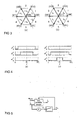
- the sector numbers are defined in Fig. 3 , which further shows phase currents corresponding to the DC-link current for a voltage reference in different sectors of the stator reference frame.
- Figure 3(a) specifically shows phase currents obtained when the lower zero voltage vector (000) is used.
- Figure 3(b) relates to using the upper zero voltage vector (111).
- Figures 3(a) and 3(b) show which phase current the DC-link current equals when the voltage reference is known, depending on the zero vector used.
- the switching states for one switching period 2 T s are shown in Fig. 4 , T s being the length of the sampling period.
- T s being the length of the sampling period.
- the results of two-phase vector modulation with the lower ( Fig. 4(a) ) and the upper ( Fig. 4(b) ) zero vectors are shown for the same voltage reference. Both methods produce the same average phase-to-phase voltage. With the lower zero voltage vector, the active voltage vectors are applied to the middle of the switching period, whereas with the upper zero voltage vector, the active voltage vectors are applied to the beginning and end of the period. In Figure 4(a) in the middle of the switching period the voltage vector is (110).
- the measured DC-link current at T s is - i c , as can be seen in Figure 3(a) .
- sampling is carried out at the beginning of the switching period, since a zero vector is applied to the middle of the switching period.
- the zero voltage vector used is (111) and the measured DC-link current at the beginning of the switching period corresponds to phase current i a when the voltage vector is (100), as can be seen in Figure 3(b) .
- Block 5 in Figure 1 carries out the above modulation and thus produces the inverter switching states h abc according to which the output switches of the inverter are turned on and off.
- the same switching states are fed to block 6, which calculates the current error, as will be described below.
- the DC-link current is sampled at uniform intervals at the beginning and in the middle of the switching period, similarly as in [11].
- One of the two current samples is obtained during an active voltage vector, and it thus corresponds to one phase current.
- the phase current available in each voltage sector is shown in Fig. 3 for both lower and upper zero voltage vectors.
- An active voltage vector in Fig. 3 has a length of 2 3 ⁇ U d , U d being the DC-link voltage.
- two phase currents can be sampled by changing the zero vector as explained above.
- the third phase current cannot be sampled until the voltage reference vector crosses a sector border.
- the current feedback is based on the current estimation error ⁇ s , which is obtained from block 6 in Figure 1 .
- the current error is updated using the phase current samples when current information is available, and kept constant if samples are not obtained.
- the current error is used as feedback in the observer 8 as presented below.
- the observer 8 also provides the estimated stator current î s for current error calculation.
- the current error is updated as follows.
- this reconstructed current can be used as feedback in the integral part of the current controller 10. Hence, the steady-state error in the current control caused by parameter errors can be avoided.
- An adaptive observer [12] 8 is used for estimating the stator current, rotor speed, and rotor position.
- the speed and position estimation is based on an estimation error between two different models; the actual motor can be considered as a reference model and the observer - including the rotor speed estimate ⁇ m - as an adjustable model.
- An error term used in an adaptation mechanism is based on the estimation error of the stator current.
- the estimated rotor speed, obtained by the adaptation mechanism, is fed back to the adjustable model.
- the adaptive observer 8 is formulated in the estimated rotor reference frame.
- a block diagram of the adaptive observer is shown in Fig. 5 .
- the adjustable model is based on a dynamic model of the motor, a stator flux being the state variable.
- L L d 0 0
- L d the estimated stator inductance matrix
- L d and L q being the estimates of the direct- and quadrature-axis inductances, respectively
- the current error is calculated based on available current samples as described above.
- the feedback gain matrix ⁇ is varied as a function of the rotor speed as explained in [12].
- F ⁇ C ⁇ i ⁇ s
- C [ 0 L q ].
- the estimate ⁇ m for the rotor position is obtained by integrating ⁇ m .
- an HF signal injection method is used to stabilize the observer.
- Demodulation and low-pass filtering results in an error signal ⁇ that is approximately proportional to ⁇ m .
- the HF excitation voltage in (12) can result in a stator voltage reference that alternates only in few sectors. As a result, one of the stator phase currents can be unavailable for a long period. In such a case, the signal injection cannot detect the rotor position reliably.
- p is a multiplier of the frequency injected to the d axis.
- the voltages injected to the d and q axes have a different frequency, and the multiplier p can thus have any value other than 1.
- the second harmonic of the excitation frequency is injected to the q axis of the estimated rotor reference frame.
- the error signal ⁇ is not affected since the demodulation is only sensitive to frequencies at ⁇ c .
- the frequency of the voltage injected to the q axis has a higher frequency than the frequency of the injected d component. This is preferred, since the lower the injected q component, the more it can disturb the current controller.
- FIG 2 shows an example of a stator voltage reference vector u s,ref in the stationary reference frame during one signal injection period.
- the signal injection according to the method of the invention is used and the voltage offset is due to the constant voltage corresponding to the full-load operation at standstill.
- Discrete voltage samples are shown as circles and also the sector borders are shown.
- the high frequency voltage amplitude u c is 0.3 p.u. and one signal injection period has 16 sampling periods, thus the sampling frequency is 16 times higher than the frequency of the HF signal.
- the amplitude of the injected voltage is selected such that it ensures movement of the voltage reference between different sectors and produces a current that can be detected despite voltage losses in the stator.
- the rotor position in Figure 2 is 45 electrical degrees and the multiplier p in (13) has a value of 2, i.e. the second harmonic of the excitation frequency is injected to the q axis. If the known signal injection were used, Figure 2 would show a voltage that oscillates only in one direction above and below the offset voltage forming a straight line.
- Signal injection block 11 also calculates the error signal ⁇ from the reconstructed stator current i s,dc , which is the sum of the current error ⁇ s and the estimated stator current î s .
- the error signal ⁇ is fed to the adaptive observer 8.
- the error signal ⁇ is used for correcting the estimated position by influencing the direction of the stator flux estimate of the adjustable model.
- both the signal injection method and the adaptive observer contribute to the rotor speed and position estimation at low speeds only.
- the influence of the HF signal injection is decreased linearly with increasing speed, reaching zero at a certain speed. At higher speeds, the estimation is based only on the adaptive observer.
- the limit at which the influence of signal injection is removed is, for example, 0.13 p.u.
- the signal injection can be removed by decreasing the amplitude of the injected signal and gain ⁇ i .
- the HF injected signal according to the invention ensures that enough samples are obtained from the HF current to obtain the required information.
- the frequency of the injected HF signal is, for example, 500Hz in the direction of d axis.
- the HF excitation voltage in equation (13) is included in the voltage reference fed to the adjustable model in equation (8). This ensures reliable prediction of the HF component in the stator current estimate î s , which is needed for calculating the current error. It is also to be noted that instead of the estimated current î s , the reconstructed stator current i s,dc has to be used for demodulation in the signal injection method.
Landscapes
- Engineering & Computer Science (AREA)
- Power Engineering (AREA)
- Control Of Ac Motors In General (AREA)
- Control Of Motors That Do Not Use Commutators (AREA)
Abstract
Description
- The present invention relates to sensorless control of permanent magnet synchronous machines (PMSM), and more particularly to control of PMSMs with DC-current measurement.
- Vector control of AC motors requires feedback from phase currents of a motor. Usually, these currents are obtained by measuring at least two of the phase currents. The currents have to be measured by devices that are electrically isolated from control electronics. Hall-effect sensors, which are commonly used for this purpose, are expensive components in low-cost frequency converters. In addition, deviations in the gains between current sensors of different phases may cause current ripple and, consequently, torque ripple. A cost-effective alternative to the phase current measurement is to measure the DC-link current of a frequency converter as in [1] T. C. Green and B. W. Williams, "Derivation of motor line-current waveforms from the DC-link current of an inverter," Proc. Inst. Elect. Eng. B, vol. 136, no. 4, pp. 196-204, July 1989. The phase currents of the motor can be estimated using the DC-link current and information on the states of inverter switches.
- Previously, several methods have been proposed for the estimation of phase currents. The phase currents can be sampled during the active voltage vectors of a direct torque controlled drive as disclosed in [2] T. Habetler and D. M. Divan, "Control strategies for direct torque control using discrete pulse modulation," IEEE Trans. Ind. Applicat., vol. 27, no. 5, pp. 893-901, Sept./Oct. 1991.
- A dynamic model of a permanent magnet synchronous motor (PMSM) is used to predict the stator current, and the phase currents are updated from the available current samples during a single three-phase pulse width modulation (PWM) cycle in [3] J. F.Moynihan, S. Bolognani, R. C. Kavanagh, M. G. Egan, and J.M. D. Murphy, "Single sensor current control of ac servodrives using digital signal processors," in Proc. EPE'93, vol. 4, Brighton, UK, Sept. 1993, pp. 415-421. Three-phase PWM can be used and multiple samples can be taken in one switching period to obtain the phase currents as disclosed in [4] F. Blaabjerg, J. K. Pedersen, U. Jaeger, and P. Thoegersen, "Single current sensor technique in the DC link of three-phase PWM-VS inverters: a review and a novel solution," IEEE Trans. Ind. Applicat., vol. 33, no. 5, pp. 1241-1253, Sept./Oct. 1997.
- Stator current information is obtained using a model for active and reactive power balance in [5] S. N. Vukosavic and A. M. Stankovic, "Sensorless induction motor drive with a single DC-link current sensor and instantaneous active and reactive power feedback," IEEE Trans. Ind. Electron., vol. 48, no. 1, pp. 195-204, Feb. 2001. A motion-sensorless scheme using a fundamental-excitation method with space-vector PWM at high speeds and an INFORM method with discrete active voltage vectors at low speeds is proposed in [6] U.-H. Rieder, M. Schroedl, and A. Ebner, "Sensorless control of an external rotor PMSM in the whole speed range including standstill using DC-link measurements only," in Proc. IEEE PESC'04, vol. 2, Aachen, Germany, June 2004, pp. 1280-1285. Phase currents can also be sampled during the active voltage vectors applied in an additional excitation voltage sequence as disclosed [7] in H. Kim and T. M. Jahns, "Phase current reconstruction for AC motor drives using a DC link single current sensor and measurement voltage vectors," IEEE Trans. Pow. Electron., vol. 21, no. 5, pp. 1413-1419, Sept. 2006.
- Some of the previous methods require modification of the inverter switching pattern [2], [7], which results in voltage and current distortion and additional losses. Methods proposed in [3], [4], [6] employ three-phase voltage modulation, which requires a variable current sampling interval to detect the phase currents. Compared with a fixed sampling interval, faster A/D conversion and signal processor are needed. The benefit of rejecting the switching frequency and its subharmonics by the synchronized sampling is also lost with a variable sampling interval, and additional compensation algorithms have to be applied. The method proposed in [4] requires four current samples in each modulation period to reject the current ripple caused by the inverter.
- Vector control of PMSM requires information on the stator currents of the machine. Costs relating to the current measurement are reduced when the current is measured from the DC-intermediate circuit of the inverter and state information on the inverter output switches are used to allocate the measured sample to the correct output phase. The stator current can then be reconstructed from these samples for control purposes.
- If the PMSM is to be controlled in low rotational speeds, a signal injection method needs to be used. In signal injection, the machine is fed with a high frequency voltage signal. This injected voltage signal causes a current which can be detected and demodulated for correcting the position estimate of the rotor. One of the problems with the above is that the traditional signal injection does not necessarily give sufficient results in connection with DC-link current measurements. This is due to the fact that DC-current measurement gives samples from the output phase currents rather irregularly, which leads to a situation where the high-frequency current originating from the injected voltage cannot be reliably determined.
- An object of the present invention is thus to provide a method so as to solve the above problem. The object of the invention is achieved by a method which is characterized by what is stated in the independent claim. Preferred embodiments of the invention are disclosed in the dependent claims.
- The invention is based on the idea of modifying the injected high-frequency voltage signal such that the position error information can be reliably determined from the measured DC-link current samples.
- In the method of the invention, the stator current and rotor speed and position are estimated in a permanent magnet synchronous machine drive, in which the current is measured from the DC-link of the inverter. The stator current estimate is corrected with the obtained current samples and the rotor speed and position are estimated with an adaptive observer that is augmented with signal injection at low rotational speeds. In the invention, the adaptive observer is used to estimate the current in the injection frequency.
- An advantage of the method and apparatus of the invention is that only one current sensor is required for sensorless control of a permanent magnet synchronous machine drive.
- The method of the invention is described in connection with a two-phase (or discontinuous) PWM used for voltage modulation. This kind of modulation is disclosed for example in documents
- [8] M. Depenbrock, "Pulse width control of a 3-phase inverter with nonsinusoidal phase voltages," in Proc. IEEE ISPC'77, 1977, pp. 399-403,
- [9] S. Ogasawara, H. Akagi, and A. Nabae, "A novel PWM scheme of voltage source inverters based on space vector theory," in Proc. EPE'89, vol. 1, Aachen, Germany, Oct. 1989, pp. 1197-1202, and
- [10] J. W. Kolar, H. Ertl, and F. C. Zach, "Influence of the modulation method on the conduction and switching losses of a PWM converter system," IEEE Trans. Ind. Applicat., vol. 27, no. 6, pp. 1063-1075, Nov./Dec. 1991.
- The invention is further described in connection with DC-current measurement, where the DC-link current is sampled at uniform intervals at the beginning and in the middle of the switching period as disclosed in [11]
EP1553692 . - An adaptive observer as disclosed in [12] A. Piippo, M. Hinkkanen, and J. Luomi, "Analysis of an adaptive observer for sensorless control of PMSM drives," in Proc. IEEE IECON'05, Raleigh, NC, Nov. 2005, pp. 1474-1479, is used for the rotor speed and position estimation, and for estimating the stator current. A modified high-frequency (HF) signal injection is used at low speeds to stabilize the estimation. The method of the invention enables stable operation in a wide speed range.
- In the following, the invention will be described in greater detail by means of preferred embodiments and with reference to the accompanying drawings, in which
-
Figure 1 shows a block diagram of a control system using the method of the invention, -
Figure 2 shows an example of a stator voltage reference with a modified injected signal, -
Figure 3 shows phase currents corresponding to DC-link current for voltage references in different sectors of a stator reference frame, -
Figure 4 shows switching states during one switching period using two-phase modulation, and -
Figure 5 shows a block diagram of an adaptive observer. - A block diagram of a control system comprising cascaded speed and current control loops is shown in
Figure 1 . Aspeed controller 9 receives an angular speed reference ωm,ref and an estimated angular speed ω̂m as feedback. Acurrent controller 10 receives a stator current reference is,ref from thespeed controller 9 and a stator current estimate îs from an observer as feedback. -
Figure 1 also shows a basic structure of a frequency converter which consists of a rectifyingbridge 1, a DC-intermediate circuit, i.e. a DC-link 3, and aninverter 2 feeding aPMSM 4. The only measured quantities needed for the control of PMSM are DC-link voltage udc and DC-link current idc at the input of theinverter 2. ω̂ m and θ̂m are the estimates of the rotor electrical angular speed and position, respectively. A current error ĩs is calculated inblock 6 using the estimated current îs , the DC-link current idc , and the references for inverter switching states habc provided by a pulse width modulation (PWM)block 5. This current error is used for feedback in anadaptive observer 8 as will be described later. The PWM-block is also shown to receive the measured DC-link voltage Udc. - A three-phase voltage-source inverter has eight discrete switching states. Six inverter states produce a non-zero phase-to-phase voltage to the three-phase load 4 (the PMSM), and they are referred to as active inverter states. The two remaining states produce a zero output voltage. The DC-link current is non-zero only during active inverter states, and has to be sampled during an active state to obtain current information.
- The DC-link current equals one phase current at a time, either ia , ib or i c , depending on the inverter switching states. The relation between the inverter switching states h abc = [ha, hb hc ] and the phase current obtainable from the DC-link current idc is given in Table 1. The switching state h of each phase is either 0 or 1, corresponding to the inverter output phase switched to the lower and the upper DC rail, respectively.
Table 1 ha h b h c i dc0 0 0 - 1 0 0 i a1 1 0 - i c0 1 0 i b0 1 1 - i a0 0 1 i c1 0 1 - i b1 1 1 - - Two-phase modulation [8] is selected as the pulse-width modulation method. The method defines the duration of the two active voltage vectors to be applied to a motor during one sampling period. The zero vector can be chosen arbitrarily without affecting the phase-to-phase voltage of the motor. In [10], the lower zero voltage vector (all phases in the negative DC rail) was used in odd sectors. On the contrary, the upper zero voltage vector (all phases in the positive DC rail) was used in odd sectors in [9]. Here, these two methods are alternated within a certain time period [11]. The sector numbers are defined in
Fig. 3 , which further shows phase currents corresponding to the DC-link current for a voltage reference in different sectors of the stator reference frame.Figure 3(a) specifically shows phase currents obtained when the lower zero voltage vector (000) is used. Correspondingly,Figure 3(b) relates to using the upper zero voltage vector (111).Figures 3(a) and 3(b) show which phase current the DC-link current equals when the voltage reference is known, depending on the zero vector used. - The switching states for one switching period 2 Ts are shown in
Fig. 4 , Ts being the length of the sampling period. The results of two-phase vector modulation with the lower (Fig. 4(a) ) and the upper (Fig. 4(b) ) zero vectors are shown for the same voltage reference. Both methods produce the same average phase-to-phase voltage. With the lower zero voltage vector, the active voltage vectors are applied to the middle of the switching period, whereas with the upper zero voltage vector, the active voltage vectors are applied to the beginning and end of the period. InFigure 4(a) in the middle of the switching period the voltage vector is (110). Since the zero voltage vector used is (000), the measured DC-link current at Ts is -ic , as can be seen inFigure 3(a) . InFigure 4(b) , sampling is carried out at the beginning of the switching period, since a zero vector is applied to the middle of the switching period. The zero voltage vector used is (111) and the measured DC-link current at the beginning of the switching period corresponds to phase current ia when the voltage vector is (100), as can be seen inFigure 3(b) . -
Block 5 inFigure 1 carries out the above modulation and thus produces the inverter switching states habc according to which the output switches of the inverter are turned on and off. The same switching states are fed to block 6, which calculates the current error, as will be described below. - The DC-link current is sampled at uniform intervals at the beginning and in the middle of the switching period, similarly as in [11]. One of the two current samples is obtained during an active voltage vector, and it thus corresponds to one phase current. By using the switching state references and the information given in Table 1, one phase current can be sampled. The phase current available in each voltage sector is shown in
Fig. 3 for both lower and upper zero voltage vectors. An active voltage vector inFig. 3 has a length of
- The current feedback is based on the current estimation error ĩs, which is obtained from
block 6 inFigure 1 . The current error is updated using the phase current samples when current information is available, and kept constant if samples are not obtained. The current error is used as feedback in theobserver 8 as presented below. Theobserver 8 also provides the estimated stator current îs for current error calculation. - The current error is updated as follows. The estimated stator current îs from the
observer 8 and the current error ĩs fromblock 6 are transformed to phase quantities in the stationary reference frame, i.e.

where

- Instead, if the current of phase b or c is available, the current error of the corresponding phase is updated. After update, the current error is transformed back to the estimated rotor reference frame using

where
Figure 1 , the above operations are carried out inblock 6. - The stator current can be reconstructed from the estimated current and the current error, i.e.

current controller 10. Hence, the steady-state error in the current control caused by parameter errors can be avoided. - An adaptive observer [12] 8 is used for estimating the stator current, rotor speed, and rotor position. The speed and position estimation is based on an estimation error between two different models; the actual motor can be considered as a reference model and the observer - including the rotor speed estimate ω̂m - as an adjustable model. An error term used in an adaptation mechanism is based on the estimation error of the stator current. The estimated rotor speed, obtained by the adaptation mechanism, is fed back to the adjustable model.
- The
adaptive observer 8 is formulated in the estimated rotor reference frame. A block diagram of the adaptive observer is shown inFig. 5 . The adjustable model is based on a dynamic model of the motor, a stator flux being the state variable. The model is defined by
where estimated quantities are marked by

where
- The adaptation is based on an error term

where C = [0 Lq ]. Hence, the current error in the estimated q direction is used for adaptation. An estimate of the electrical angular speed of the rotor is obtained by a PI speed adaptation mechanism
where kp and ki are non-negative gains. The estimate θ̂m, for the rotor position is obtained by integrating ω̂m. - Since the adaptive observer cannot perform well at low speeds due to inaccuracies in measurements and parameter estimates, an HF signal injection method is used to stabilize the observer. In the signal injection presented in [13], a carrier excitation signal alternating at angular frequency ω c , and having an amplitude u c , i.e.

- At low speeds, the HF excitation voltage in (12) can result in a stator voltage reference that alternates only in few sectors. As a result, one of the stator phase currents can be unavailable for a long period. In such a case, the signal injection cannot detect the rotor position reliably. For better sector coverage, a modified HF excitation voltage

- The injection is carried out in the block diagram of
Figure 1 , block 11, which produces the voltage signal u c that is added to the output of thecurrent controller 10. The sum of the high frequency voltage signal and the output of the current controller is the stator voltage reference us,ref that is fed to theobserver 8 and toPWM block 5 via co-ordinatetransformation block 7. -
Figure 2 shows an example of a stator voltage reference vector us,ref in the stationary reference frame during one signal injection period. InFigure 2 , the signal injection according to the method of the invention is used and the voltage offset is due to the constant voltage corresponding to the full-load operation at standstill. Discrete voltage samples are shown as circles and also the sector borders are shown. InFigure 2 , the high frequency voltage amplitude uc is 0.3 p.u. and one signal injection period has 16 sampling periods, thus the sampling frequency is 16 times higher than the frequency of the HF signal. The amplitude of the injected voltage is selected such that it ensures movement of the voltage reference between different sectors and produces a current that can be detected despite voltage losses in the stator. The rotor position inFigure 2 is 45 electrical degrees and the multiplier p in (13) has a value of 2, i.e. the second harmonic of the excitation frequency is injected to the q axis. If the known signal injection were used,Figure 2 would show a voltage that oscillates only in one direction above and below the offset voltage forming a straight line. -
Signal injection block 11 also calculates the error signal ε from the reconstructed stator current i s,dc , which is the sum of the current error ĩ s and the estimated stator current î s . The error signal ε is fed to theadaptive observer 8. - The error signal ε is used for correcting the estimated position by influencing the direction of the stator flux estimate of the adjustable model. The algorithm is given by


where γ p and γi are the gains of the PI mechanism driving the error signal ε, to zero. - In a preferred embodiment of the invention, both the signal injection method and the adaptive observer contribute to the rotor speed and position estimation at low speeds only. Preferably, the influence of the HF signal injection is decreased linearly with increasing speed, reaching zero at a certain speed. At higher speeds, the estimation is based only on the adaptive observer. The limit at which the influence of signal injection is removed is, for example, 0.13 p.u. The signal injection can be removed by decreasing the amplitude of the injected signal and gain γi. The HF injected signal according to the invention ensures that enough samples are obtained from the HF current to obtain the required information. The frequency of the injected HF signal is, for example, 500Hz in the direction of d axis.
- It is noted that the HF excitation voltage in equation (13) is included in the voltage reference fed to the adjustable model in equation (8). This ensures reliable prediction of the HF component in the stator current estimate î s , which is needed for calculating the current error. It is also to be noted that instead of the estimated current î s , the reconstructed stator current is,dc has to be used for demodulation in the signal injection method.
- In the above description, the method of the invention is described in connection with only one possible control system. It is, however, clear that the method of the invention can also be utilized in connection with other types or control systems. It will be obvious to a person skilled in the art that as technology advances, the inventive concept can be implemented in various ways. The invention and its embodiments are not limited to the examples described above but may vary within the scope of the claims.
Claims (4)
- A method for sensorless estimation of rotor speed and position of a permanent magnet synchronous machine, when the permanent magnet synchronous machine is fed with a frequency converter, the method comprising the steps of
forming a stator voltage reference for the permanent magnet synchronous machine,
injecting a high frequency signal (u c ) into the stator voltage reference,
measuring a DC-link current (idc ) of the frequency converter when the permanent magnet synchronous machine (4) is fed with a voltage (us,ref ) corresponding to a sum of the stator voltage reference and the injected signal,
calculating a stator current estimate (î s ),
calculating a current error (ĩ s ) as a difference between the stator current estimate and the measured DC-link current, and
estimating a rotor speed (ω̂ m ) and position (θ̂ m ) of the permanent magnet synchronous machine based on the current error, characterized in that the injected high frequency signal (u c ) comprises a direct axis component and a quadrature axis component, the direct axis component having a first frequency and the quadrature axis component having a second frequency, the first and second frequencies being different. - A method according to claim 1, characterized in that the stator current estimate (î s ) is calculated using an adaptive observer (8).
- A method according to claim 1 or 2, characterized in that the second frequency is higher than the first frequency.
- A method according to claim 2 or 3, characterized in that the adaptive observer receives the sum of the stator voltage reference and the injected voltage signal (u s,ref ) and an error signal (ε) which relates to an angle estimation error originating from the injected voltage and which is obtainable from a stator current, and which error signal is demodulated from the sum of the current error (ĩ s ) and the stator current estimate (î s ).
Priority Applications (4)
| Application Number | Priority Date | Filing Date | Title |
|---|---|---|---|
| DE602007008045T DE602007008045D1 (en) | 2007-01-12 | 2007-01-12 | Method for estimating the rotor speed and position of a synchronous permanent magnet machine without position encoder |
| EP07100472A EP1944860B9 (en) | 2007-01-12 | 2007-01-12 | A method for sensorless estimation of rotor speed and position of a permanent magnet synchronous machine |
| AT07100472T ATE476010T1 (en) | 2007-01-12 | 2007-01-12 | METHOD FOR ESTIMATING THE ROTOR SPEED AND POSITION OF A SYNCHRONOUS PERMANENT MAGNET MACHINE WITHOUT A POSITION ENCODER |
| US11/972,667 US7759897B2 (en) | 2007-01-12 | 2008-01-11 | Method for sensorless estimation of rotor speed and position of a permanent magnet synchronous machine |
Applications Claiming Priority (1)
| Application Number | Priority Date | Filing Date | Title |
|---|---|---|---|
| EP07100472A EP1944860B9 (en) | 2007-01-12 | 2007-01-12 | A method for sensorless estimation of rotor speed and position of a permanent magnet synchronous machine |
Publications (3)
| Publication Number | Publication Date |
|---|---|
| EP1944860A1 EP1944860A1 (en) | 2008-07-16 |
| EP1944860B1 EP1944860B1 (en) | 2010-07-28 |
| EP1944860B9 true EP1944860B9 (en) | 2010-10-20 |
Family
ID=38162131
Family Applications (1)
| Application Number | Title | Priority Date | Filing Date |
|---|---|---|---|
| EP07100472A Active EP1944860B9 (en) | 2007-01-12 | 2007-01-12 | A method for sensorless estimation of rotor speed and position of a permanent magnet synchronous machine |
Country Status (4)
| Country | Link |
|---|---|
| US (1) | US7759897B2 (en) |
| EP (1) | EP1944860B9 (en) |
| AT (1) | ATE476010T1 (en) |
| DE (1) | DE602007008045D1 (en) |
Cited By (1)
| Publication number | Priority date | Publication date | Assignee | Title |
|---|---|---|---|---|
| DE102014102376A1 (en) | 2014-02-24 | 2015-08-27 | Jenaer Antriebstechnik Gmbh | Rotary field machine and method for determining the angular position of its rotor |
Families Citing this family (43)
| Publication number | Priority date | Publication date | Assignee | Title |
|---|---|---|---|---|
| EP2023479B1 (en) * | 2007-08-06 | 2014-04-16 | Baumüller Nürnberg Gmbh | System for seamless velocity and/or location determination including standstill for a permanent magnet rotor of an electric machine |
| US8384338B2 (en) * | 2009-01-30 | 2013-02-26 | Eaton Corporation | System and method for determining stator winding resistance in an AC motor using motor drives |
| FR2944659B1 (en) * | 2009-04-21 | 2011-04-01 | Schneider Toshiba Inverter | METHOD FOR DETERMINING THE POSITION OF THE FLOW VECTOR OF AN ENGINE |
| JP5289567B2 (en) * | 2009-06-08 | 2013-09-11 | 三菱電機株式会社 | Power converter |
| US8339081B2 (en) * | 2009-09-11 | 2012-12-25 | GM Global Technology Operations LLC | Method and apparatus for low speed permanent magnet motor operation |
| US8503207B2 (en) * | 2010-09-29 | 2013-08-06 | Rockwell Automation Technologies, Inc. | Discontinuous pulse width drive modulation method and apparatus for reduction of common-mode voltage in power conversion systems |
| US8624564B2 (en) * | 2010-12-23 | 2014-01-07 | Caterpillar Inc. | Switched reluctance generator initial rotor position estimation |
| KR101761740B1 (en) * | 2011-02-01 | 2017-07-26 | 삼성전자 주식회사 | Apparatus for estimating inductance of permanent magnet synchronous motor and method the same |
| JP5348153B2 (en) * | 2011-02-14 | 2013-11-20 | 株式会社デンソー | Rotating machine control device |
| DE102011011804A1 (en) | 2011-02-19 | 2012-08-23 | Volkswagen Ag | Method for controlling electric machine utilized as e.g. main drive in seemless land vehicle e.g. passenger vehicle, involves orienting stator flux through magnets of machine and energized windings arranged in rotor and/or stator parts |
| DE102011076734A1 (en) * | 2011-05-30 | 2012-12-06 | Robert Bosch Gmbh | Method and device for angle estimation in a synchronous machine |
| US8796982B2 (en) * | 2011-12-15 | 2014-08-05 | Eaton Corporation | System and method for detecting phase loss and diagnosing DC link capacitor health in an adjustable speed drive |
| CN102570959A (en) * | 2011-12-31 | 2012-07-11 | 南京理工大学 | Control system and control method for low-voltage high-current permanent magnet synchronous motors |
| JP5733251B2 (en) * | 2012-03-27 | 2015-06-10 | 株式会社デンソー | Position detection device |
| US8710783B2 (en) * | 2012-05-15 | 2014-04-29 | Panasonic Corporation | Motor control system, motor control device, and brushless motor |
| CN102843089B (en) * | 2012-08-23 | 2014-11-05 | 四川长虹电器股份有限公司 | Control method of permanent magnet synchronous motor (PMSM) for frequency conversion refrigerator |
| JP5737445B2 (en) | 2013-03-05 | 2015-06-17 | ダイキン工業株式会社 | Power converter control device |
| US9054586B2 (en) | 2013-03-15 | 2015-06-09 | Rockwell Automation Technologies, Inc. | Methods and apparatus for continuous and discontinuous active rectifier boost operation to increase power converter rating |
| JP6150211B2 (en) * | 2013-08-09 | 2017-06-21 | 有限会社シー・アンド・エス国際研究所 | Digital rotor phase speed estimation device for AC motor |
| JP6150212B2 (en) * | 2013-08-18 | 2017-06-21 | 有限会社シー・アンド・エス国際研究所 | Digital rotor phase speed estimation device for AC motor |
| CN103414423A (en) * | 2013-08-22 | 2013-11-27 | 东南大学 | Surface-mounted permanent magnet synchronous motor sensorless direct torque control method |
| JP6017057B2 (en) * | 2013-10-22 | 2016-10-26 | 三菱電機株式会社 | Motor control device |
| US9236828B1 (en) | 2014-07-03 | 2016-01-12 | Rockwell Automation Technologies, Inc. | Methods and power conversion system control apparatus to control IGBT junction temperature at low speed |
| US9318976B1 (en) | 2014-10-30 | 2016-04-19 | Rockwell Automation Technologies, Inc. | Adjustable PWM method to increase low speed starting torque and inverter voltage measurement accuracy |
| US9595903B2 (en) | 2015-03-20 | 2017-03-14 | General Electric Company | Controller for motor |
| US10830610B2 (en) * | 2016-09-26 | 2020-11-10 | Analog Devices, Inc. | Method and apparatus for motor rotor position determination |
| CN108631680B (en) * | 2017-03-22 | 2022-06-03 | 操纵技术Ip控股公司 | Permanent magnet synchronous machine and method for determining position of motor by using vibration induction salient pole |
| US10291160B1 (en) * | 2018-03-09 | 2019-05-14 | Haier Us Appliance Solutions, Inc. | Method for operating a synchronous motor |
| RU2715213C1 (en) * | 2018-12-03 | 2020-02-26 | Общество с ограниченной ответственностью "НПФ ВЕКТОР" | Method for determination of rotor angular position of electric motors of synchronous machines class with excitation winding |
| CN110048654B (en) * | 2019-03-21 | 2021-11-23 | 上海淞宸动力科技有限公司 | Rotor position estimation method for permanent magnet synchronous motor |
| US11374520B2 (en) | 2019-06-10 | 2022-06-28 | Black & Decker Inc. | Field-oriented sensorless brushless motor control in a power tool |
| US10784797B1 (en) | 2019-06-19 | 2020-09-22 | Rockwell Automation Technologies, Inc. | Bootstrap charging by PWM control |
| CN110413014B (en) * | 2019-08-29 | 2022-01-28 | 河南东旺熙朝实业有限公司 | Speed control circuit of aluminum extruder |
| EP3809578B1 (en) * | 2019-10-15 | 2024-08-21 | ABB Schweiz AG | Method for starting a synchronous motor |
| CN110995100A (en) * | 2019-12-12 | 2020-04-10 | 华中科技大学 | Position-sensorless control method and system for permanent magnet synchronous motor |
| RU2746795C1 (en) * | 2020-07-07 | 2021-04-21 | Федеральное государственное унитарное предприятие "Крыловский государственный научный центр" | Method of frequency control of an electric drive with a synchronous engine without a rotor position sensor |
| CN111953250B (en) * | 2020-08-05 | 2022-07-22 | 南京邮电大学 | Harmonic current injection permanent magnet synchronous motor torque ripple suppression method |
| CN112019121B (en) * | 2020-08-31 | 2021-12-07 | 合肥工业大学 | Permanent magnet synchronous motor current loop control method based on discrete extended state observer |
| US11336206B2 (en) | 2020-09-23 | 2022-05-17 | Rockwell Automation Technoligies, Inc. | Switching frequency and PWM control to extend power converter lifetime |
| CN114123904B (en) * | 2021-06-10 | 2023-08-08 | 浙江大学先进电气装备创新中心 | Predictive current increment control method suitable for operation of permanent magnet synchronous motor in high-speed region |
| CN113708691B (en) * | 2021-09-01 | 2023-12-22 | 广东汇天航空航天科技有限公司 | Rotor operation data estimation method, computing equipment, motor control method and system |
| CN114204866B (en) * | 2021-12-16 | 2024-01-16 | 上海氢恒汽车电子有限公司 | Rotor speed and position determining method of permanent magnet synchronous motor |
| CN115021629B (en) * | 2022-07-11 | 2024-03-12 | 中国矿业大学 | Permanent magnet motor current one-step compensation reconstruction method based on fixed sampling interval |
Family Cites Families (8)
| Publication number | Priority date | Publication date | Assignee | Title |
|---|---|---|---|---|
| US6069467A (en) * | 1998-11-16 | 2000-05-30 | General Electric Company | Sensorless rotor tracking of induction machines with asymmetrical rotor resistance |
| US6163127A (en) * | 1999-11-22 | 2000-12-19 | General Motors Corporation | System and method for controlling a position sensorless permanent magnet motor |
| GB0220401D0 (en) * | 2002-09-03 | 2002-10-09 | Trw Ltd | Motor drive control |
| US6763622B2 (en) * | 2002-10-10 | 2004-07-20 | General Motors Corporation | Amplitude detection method and apparatus for high frequency impedance tracking sensorless algorithm |
| FI115873B (en) * | 2003-09-05 | 2005-07-29 | Abb Oy | Method in connection with an open pole permanent magnet synchronous machine |
| FI116337B (en) | 2003-12-19 | 2005-10-31 | Abb Oy | A method for determining the output currents in a frequency converter |
| DE602004020349D1 (en) * | 2004-10-28 | 2009-05-14 | Abb Oy | Method for estimating the rotor speed and position of a permanent magnet synchronous machine |
| US7088077B2 (en) * | 2004-11-09 | 2006-08-08 | General Motors Corporation | Position-sensorless control of interior permanent magnet machines |
-
2007
- 2007-01-12 DE DE602007008045T patent/DE602007008045D1/en active Active
- 2007-01-12 EP EP07100472A patent/EP1944860B9/en active Active
- 2007-01-12 AT AT07100472T patent/ATE476010T1/en not_active IP Right Cessation
-
2008
- 2008-01-11 US US11/972,667 patent/US7759897B2/en active Active
Cited By (2)
| Publication number | Priority date | Publication date | Assignee | Title |
|---|---|---|---|---|
| DE102014102376A1 (en) | 2014-02-24 | 2015-08-27 | Jenaer Antriebstechnik Gmbh | Rotary field machine and method for determining the angular position of its rotor |
| DE102014102376B4 (en) | 2014-02-24 | 2018-05-30 | Jenaer Antriebstechnik Gmbh | Rotary field machine and method for determining the angular position of its rotor |
Also Published As
| Publication number | Publication date |
|---|---|
| DE602007008045D1 (en) | 2010-09-09 |
| US20080169782A1 (en) | 2008-07-17 |
| ATE476010T1 (en) | 2010-08-15 |
| US7759897B2 (en) | 2010-07-20 |
| EP1944860B1 (en) | 2010-07-28 |
| EP1944860A1 (en) | 2008-07-16 |
Similar Documents
| Publication | Publication Date | Title |
|---|---|---|
| EP1944860B9 (en) | A method for sensorless estimation of rotor speed and position of a permanent magnet synchronous machine | |
| US6650081B2 (en) | Synchronous motor driving system | |
| JP3982232B2 (en) | Sensorless control device and control method for synchronous generator | |
| US7525269B2 (en) | Method and apparatus for sensorless position control of a permanent magnet synchronous motor (PMSM) drive system | |
| US10944346B2 (en) | Device and a method for estimating inductances of an electric machine | |
| KR101046802B1 (en) | Control device of AC rotor and electric constant measurement method of AC rotor using this controller | |
| JP3692046B2 (en) | Motor control device | |
| JP3843391B2 (en) | Synchronous motor drive | |
| US7072790B2 (en) | Shaft sensorless angular position and velocity estimation for a dynamoelectric machine based on extended rotor flux | |
| WO1991012656A1 (en) | Method and apparatus for controlling an ac induction motor by indirect measurement of the air-gap voltage | |
| JP2000102300A (en) | Method and device for controlling ac motor | |
| JP2000175483A (en) | Sensorless control method for synchronous motor and its apparatus | |
| JP2008206330A (en) | Device and method for estimating magnetic pole position of synchronous electric motor | |
| JP4670162B2 (en) | Control device for synchronous motor | |
| JP2004289898A (en) | Drive device for stepping motor | |
| Guan et al. | Performance comparison of two FPE sensorless control methods on a direct torque controlled interior permanent magnet synchronous motor drive | |
| EP3474438B1 (en) | Motor control device and control method | |
| KR102409792B1 (en) | Control device of permanent magnet synchronization electric motor, microcomputer, electric motor system, and driving method of permanent magnet synchronization electric motor | |
| Piippo et al. | Sensorless PMSM drive with DC-link current measurement | |
| JP2001078494A (en) | Method of correcting dc offset of ac motor driver | |
| Guan et al. | Sensorless control interior permanent-magnet synchronous motor drive over wide speed range operation based on the current derivative method | |
| Piippo | An adaptive observer with signal injection for interior permanent magnet synchronous motors | |
| Luukko et al. | Estimation of rotor and load angle of direct-torque-controlled permanent magnet synchronous machine drive | |
| Eskola et al. | Indirect matrix converter fed PMSM-sensorless control using carrier injection | |
| JP4590755B2 (en) | Control device for synchronous motor |
Legal Events
| Date | Code | Title | Description |
|---|---|---|---|
| PUAI | Public reference made under article 153(3) epc to a published international application that has entered the european phase |
Free format text: ORIGINAL CODE: 0009012 |
|
| AK | Designated contracting states |
Kind code of ref document: A1 Designated state(s): AT BE BG CH CY CZ DE DK EE ES FI FR GB GR HU IE IS IT LI LT LU LV MC NL PL PT RO SE SI SK TR |
|
| AX | Request for extension of the european patent |
Extension state: AL BA HR MK RS |
|
| 17P | Request for examination filed |
Effective date: 20081008 |
|
| AKX | Designation fees paid |
Designated state(s): AT BE BG CH CY CZ DE DK EE ES FI FR GB GR HU IE IS IT LI LT LU LV MC NL PL PT RO SE SI SK TR |
|
| GRAP | Despatch of communication of intention to grant a patent |
Free format text: ORIGINAL CODE: EPIDOSNIGR1 |
|
| GRAS | Grant fee paid |
Free format text: ORIGINAL CODE: EPIDOSNIGR3 |
|
| GRAA | (expected) grant |
Free format text: ORIGINAL CODE: 0009210 |
|
| AK | Designated contracting states |
Kind code of ref document: B1 Designated state(s): AT BE BG CH CY CZ DE DK EE ES FI FR GB GR HU IE IS IT LI LT LU LV MC NL PL PT RO SE SI SK TR |
|
| REG | Reference to a national code |
Ref country code: GB Ref legal event code: FG4D |
|
| REG | Reference to a national code |
Ref country code: CH Ref legal event code: EP |
|
| REG | Reference to a national code |
Ref country code: IE Ref legal event code: FG4D |
|
| REF | Corresponds to: |
Ref document number: 602007008045 Country of ref document: DE Date of ref document: 20100909 Kind code of ref document: P |
|
| REG | Reference to a national code |
Ref country code: NL Ref legal event code: VDEP Effective date: 20100728 |
|
| LTIE | Lt: invalidation of european patent or patent extension |
Effective date: 20100728 |
|
| PG25 | Lapsed in a contracting state [announced via postgrant information from national office to epo] |
Ref country code: LT Free format text: LAPSE BECAUSE OF FAILURE TO SUBMIT A TRANSLATION OF THE DESCRIPTION OR TO PAY THE FEE WITHIN THE PRESCRIBED TIME-LIMIT Effective date: 20100728 Ref country code: AT Free format text: LAPSE BECAUSE OF FAILURE TO SUBMIT A TRANSLATION OF THE DESCRIPTION OR TO PAY THE FEE WITHIN THE PRESCRIBED TIME-LIMIT Effective date: 20100728 Ref country code: NL Free format text: LAPSE BECAUSE OF FAILURE TO SUBMIT A TRANSLATION OF THE DESCRIPTION OR TO PAY THE FEE WITHIN THE PRESCRIBED TIME-LIMIT Effective date: 20100728 |
|
| PG25 | Lapsed in a contracting state [announced via postgrant information from national office to epo] |
Ref country code: SI Free format text: LAPSE BECAUSE OF FAILURE TO SUBMIT A TRANSLATION OF THE DESCRIPTION OR TO PAY THE FEE WITHIN THE PRESCRIBED TIME-LIMIT Effective date: 20100728 Ref country code: BG Free format text: LAPSE BECAUSE OF FAILURE TO SUBMIT A TRANSLATION OF THE DESCRIPTION OR TO PAY THE FEE WITHIN THE PRESCRIBED TIME-LIMIT Effective date: 20101028 Ref country code: CY Free format text: LAPSE BECAUSE OF FAILURE TO SUBMIT A TRANSLATION OF THE DESCRIPTION OR TO PAY THE FEE WITHIN THE PRESCRIBED TIME-LIMIT Effective date: 20100728 Ref country code: IS Free format text: LAPSE BECAUSE OF FAILURE TO SUBMIT A TRANSLATION OF THE DESCRIPTION OR TO PAY THE FEE WITHIN THE PRESCRIBED TIME-LIMIT Effective date: 20101128 Ref country code: PL Free format text: LAPSE BECAUSE OF FAILURE TO SUBMIT A TRANSLATION OF THE DESCRIPTION OR TO PAY THE FEE WITHIN THE PRESCRIBED TIME-LIMIT Effective date: 20100728 Ref country code: PT Free format text: LAPSE BECAUSE OF FAILURE TO SUBMIT A TRANSLATION OF THE DESCRIPTION OR TO PAY THE FEE WITHIN THE PRESCRIBED TIME-LIMIT Effective date: 20101129 |
|
| PG25 | Lapsed in a contracting state [announced via postgrant information from national office to epo] |
Ref country code: BE Free format text: LAPSE BECAUSE OF FAILURE TO SUBMIT A TRANSLATION OF THE DESCRIPTION OR TO PAY THE FEE WITHIN THE PRESCRIBED TIME-LIMIT Effective date: 20100728 Ref country code: GR Free format text: LAPSE BECAUSE OF FAILURE TO SUBMIT A TRANSLATION OF THE DESCRIPTION OR TO PAY THE FEE WITHIN THE PRESCRIBED TIME-LIMIT Effective date: 20101029 Ref country code: SE Free format text: LAPSE BECAUSE OF FAILURE TO SUBMIT A TRANSLATION OF THE DESCRIPTION OR TO PAY THE FEE WITHIN THE PRESCRIBED TIME-LIMIT Effective date: 20100728 Ref country code: LV Free format text: LAPSE BECAUSE OF FAILURE TO SUBMIT A TRANSLATION OF THE DESCRIPTION OR TO PAY THE FEE WITHIN THE PRESCRIBED TIME-LIMIT Effective date: 20100728 |
|
| PG25 | Lapsed in a contracting state [announced via postgrant information from national office to epo] |
Ref country code: DK Free format text: LAPSE BECAUSE OF FAILURE TO SUBMIT A TRANSLATION OF THE DESCRIPTION OR TO PAY THE FEE WITHIN THE PRESCRIBED TIME-LIMIT Effective date: 20100728 |
|
| PG25 | Lapsed in a contracting state [announced via postgrant information from national office to epo] |
Ref country code: SK Free format text: LAPSE BECAUSE OF FAILURE TO SUBMIT A TRANSLATION OF THE DESCRIPTION OR TO PAY THE FEE WITHIN THE PRESCRIBED TIME-LIMIT Effective date: 20100728 Ref country code: EE Free format text: LAPSE BECAUSE OF FAILURE TO SUBMIT A TRANSLATION OF THE DESCRIPTION OR TO PAY THE FEE WITHIN THE PRESCRIBED TIME-LIMIT Effective date: 20100728 Ref country code: RO Free format text: LAPSE BECAUSE OF FAILURE TO SUBMIT A TRANSLATION OF THE DESCRIPTION OR TO PAY THE FEE WITHIN THE PRESCRIBED TIME-LIMIT Effective date: 20100728 Ref country code: CZ Free format text: LAPSE BECAUSE OF FAILURE TO SUBMIT A TRANSLATION OF THE DESCRIPTION OR TO PAY THE FEE WITHIN THE PRESCRIBED TIME-LIMIT Effective date: 20100728 |
|
| PLBE | No opposition filed within time limit |
Free format text: ORIGINAL CODE: 0009261 |
|
| STAA | Information on the status of an ep patent application or granted ep patent |
Free format text: STATUS: NO OPPOSITION FILED WITHIN TIME LIMIT |
|
| PG25 | Lapsed in a contracting state [announced via postgrant information from national office to epo] |
Ref country code: ES Free format text: LAPSE BECAUSE OF FAILURE TO SUBMIT A TRANSLATION OF THE DESCRIPTION OR TO PAY THE FEE WITHIN THE PRESCRIBED TIME-LIMIT Effective date: 20101108 |
|
| 26N | No opposition filed |
Effective date: 20110429 |
|
| REG | Reference to a national code |
Ref country code: DE Ref legal event code: R097 Ref document number: 602007008045 Country of ref document: DE Effective date: 20110429 |
|
| PG25 | Lapsed in a contracting state [announced via postgrant information from national office to epo] |
Ref country code: MC Free format text: LAPSE BECAUSE OF NON-PAYMENT OF DUE FEES Effective date: 20110131 |
|
| REG | Reference to a national code |
Ref country code: CH Ref legal event code: PL |
|
| REG | Reference to a national code |
Ref country code: IE Ref legal event code: MM4A |
|
| PG25 | Lapsed in a contracting state [announced via postgrant information from national office to epo] |
Ref country code: CH Free format text: LAPSE BECAUSE OF NON-PAYMENT OF DUE FEES Effective date: 20110131 Ref country code: LI Free format text: LAPSE BECAUSE OF NON-PAYMENT OF DUE FEES Effective date: 20110131 |
|
| PG25 | Lapsed in a contracting state [announced via postgrant information from national office to epo] |
Ref country code: IE Free format text: LAPSE BECAUSE OF NON-PAYMENT OF DUE FEES Effective date: 20110112 |
|
| PG25 | Lapsed in a contracting state [announced via postgrant information from national office to epo] |
Ref country code: LU Free format text: LAPSE BECAUSE OF NON-PAYMENT OF DUE FEES Effective date: 20110112 |
|
| PG25 | Lapsed in a contracting state [announced via postgrant information from national office to epo] |
Ref country code: TR Free format text: LAPSE BECAUSE OF FAILURE TO SUBMIT A TRANSLATION OF THE DESCRIPTION OR TO PAY THE FEE WITHIN THE PRESCRIBED TIME-LIMIT Effective date: 20100728 |
|
| PG25 | Lapsed in a contracting state [announced via postgrant information from national office to epo] |
Ref country code: HU Free format text: LAPSE BECAUSE OF FAILURE TO SUBMIT A TRANSLATION OF THE DESCRIPTION OR TO PAY THE FEE WITHIN THE PRESCRIBED TIME-LIMIT Effective date: 20100728 |
|
| REG | Reference to a national code |
Ref country code: FR Ref legal event code: PLFP Year of fee payment: 10 |
|
| REG | Reference to a national code |
Ref country code: FR Ref legal event code: PLFP Year of fee payment: 11 |
|
| REG | Reference to a national code |
Ref country code: FR Ref legal event code: PLFP Year of fee payment: 12 |
|
| REG | Reference to a national code |
Ref country code: GB Ref legal event code: 732E Free format text: REGISTERED BETWEEN 20180823 AND 20180829 |
|
| REG | Reference to a national code |
Ref country code: DE Ref legal event code: R082 Ref document number: 602007008045 Country of ref document: DE Representative=s name: DOMPATENT VON KREISLER SELTING WERNER - PARTNE, DE Ref country code: DE Ref legal event code: R081 Ref document number: 602007008045 Country of ref document: DE Owner name: ABB SCHWEIZ AG, CH Free format text: FORMER OWNER: ABB OY, HELSINKI, FI |
|
| PGFP | Annual fee paid to national office [announced via postgrant information from national office to epo] |
Ref country code: FI Payment date: 20210121 Year of fee payment: 15 |
|
| PGFP | Annual fee paid to national office [announced via postgrant information from national office to epo] |
Ref country code: DE Payment date: 20210120 Year of fee payment: 15 |
|
| REG | Reference to a national code |
Ref country code: DE Ref legal event code: R119 Ref document number: 602007008045 Country of ref document: DE |
|
| REG | Reference to a national code |
Ref country code: FI Ref legal event code: MAE |
|
| PG25 | Lapsed in a contracting state [announced via postgrant information from national office to epo] |
Ref country code: FI Free format text: LAPSE BECAUSE OF NON-PAYMENT OF DUE FEES Effective date: 20220112 Ref country code: DE Free format text: LAPSE BECAUSE OF NON-PAYMENT OF DUE FEES Effective date: 20220802 |
|
| PGFP | Annual fee paid to national office [announced via postgrant information from national office to epo] |
Ref country code: GB Payment date: 20240119 Year of fee payment: 18 |
|
| PGFP | Annual fee paid to national office [announced via postgrant information from national office to epo] |
Ref country code: IT Payment date: 20240129 Year of fee payment: 18 Ref country code: FR Payment date: 20240124 Year of fee payment: 18 |