EP1944776B1 - Getriebe-Einheit und Verwendung derselben - Google Patents
Getriebe-Einheit und Verwendung derselben Download PDFInfo
- Publication number
- EP1944776B1 EP1944776B1 EP07405011A EP07405011A EP1944776B1 EP 1944776 B1 EP1944776 B1 EP 1944776B1 EP 07405011 A EP07405011 A EP 07405011A EP 07405011 A EP07405011 A EP 07405011A EP 1944776 B1 EP1944776 B1 EP 1944776B1
- Authority
- EP
- European Patent Office
- Prior art keywords
- gear unit
- unit according
- race ring
- gear
- enclosure
- Prior art date
- Legal status (The legal status is an assumption and is not a legal conclusion. Google has not performed a legal analysis and makes no representation as to the accuracy of the status listed.)
- Not-in-force
Links
- 230000005540 biological transmission Effects 0.000 title description 11
- 230000009467 reduction Effects 0.000 claims abstract description 9
- 230000008878 coupling Effects 0.000 claims description 4
- 238000010168 coupling process Methods 0.000 claims description 4
- 238000005859 coupling reaction Methods 0.000 claims description 4
- 239000002184 metal Substances 0.000 claims description 4
- 229920003023 plastic Polymers 0.000 claims description 4
- 239000000853 adhesive Substances 0.000 claims description 3
- 230000001070 adhesive effect Effects 0.000 claims description 3
- 239000004033 plastic Substances 0.000 claims description 3
- 239000000919 ceramic Substances 0.000 claims 1
- 238000009413 insulation Methods 0.000 claims 1
- 239000002991 molded plastic Substances 0.000 claims 1
- 238000007789 sealing Methods 0.000 claims 1
- 239000003990 capacitor Substances 0.000 description 3
- 239000000463 material Substances 0.000 description 3
- 238000010276 construction Methods 0.000 description 2
- 229910000639 Spring steel Inorganic materials 0.000 description 1
- 229910000831 Steel Inorganic materials 0.000 description 1
- 230000008901 benefit Effects 0.000 description 1
- 229910010293 ceramic material Inorganic materials 0.000 description 1
- 230000008859 change Effects 0.000 description 1
- 230000001419 dependent effect Effects 0.000 description 1
- 239000011521 glass Substances 0.000 description 1
- 238000002347 injection Methods 0.000 description 1
- 239000007924 injection Substances 0.000 description 1
- 230000002045 lasting effect Effects 0.000 description 1
- 230000007774 longterm Effects 0.000 description 1
- 238000000034 method Methods 0.000 description 1
- 229920000642 polymer Polymers 0.000 description 1
- 230000008569 process Effects 0.000 description 1
- 229910052594 sapphire Inorganic materials 0.000 description 1
- 239000010980 sapphire Substances 0.000 description 1
- 239000010959 steel Substances 0.000 description 1
- 208000008918 voyeurism Diseases 0.000 description 1
Images

Classifications
-
- H—ELECTRICITY
- H01—ELECTRIC ELEMENTS
- H01C—RESISTORS
- H01C10/00—Adjustable resistors
- H01C10/14—Adjustable resistors adjustable by auxiliary driving means
-
- F—MECHANICAL ENGINEERING; LIGHTING; HEATING; WEAPONS; BLASTING
- F16—ENGINEERING ELEMENTS AND UNITS; GENERAL MEASURES FOR PRODUCING AND MAINTAINING EFFECTIVE FUNCTIONING OF MACHINES OR INSTALLATIONS; THERMAL INSULATION IN GENERAL
- F16H—GEARING
- F16H13/00—Gearing for conveying rotary motion with constant gear ratio by friction between rotary members
- F16H13/06—Gearing for conveying rotary motion with constant gear ratio by friction between rotary members with members having orbital motion
- F16H13/08—Gearing for conveying rotary motion with constant gear ratio by friction between rotary members with members having orbital motion with balls or with rollers acting in a similar manner
Definitions
- the invention relates to a transmission unit for combination with a manually adjustable electrical component with a reduction gear, as well as the use thereof.
- the dependent claims indicate embodiments of the inventions.
- a comparable newer reduction gear of the same kind is in the US 3,951,001 from 1976 described.
- a coil spring is provided, which increases the adhesion pressure between the balls and the treads.
- An object of the invention is to provide a gear unit using the aforementioned type of reduction gears, which is constructed and dimensioned in contemporary electrical / electronic construction and whose dimensions do not significantly exceed the size of 1 x 1 x 1 cm.
- the unit should continue to be easily combinable with various electrical / electronic components and fully comply with the EMC standards regarding dielectric strength.
- Such a transmission unit is defined by the independent claim 1.
- This gear unit forms an independent, mechanical component that is suitable for combining with components on printed circuit boards, especially with rotary potentiometers.
- the gear unit should be robust and splash-proof and thus suitable for harsh operating conditions.
- the gear unit according to claim 2 is equipped with a housing unit, which represents a robust protection of the internal components against all external influences. Further, the unit is resistant to bumps because it has no parts that have mutually free play.
- Fig. 1 shows an exploded perspective view of the transmission unit 11 and coupled to this electrical / electronic component 12, in particular a rotational resistance or a Drehpotentiometers.
- This device 12 is designed for mounting on a flat, not shown, printed circuit board, on the two further LEDs (LED) 13, 14 may be mounted.
- the electrical component 12 has in its adjustment axis 16 for the purpose of manual adjustability, a slot 15 into which, for example, a screwdriver can be inserted.
- the gear unit 11 mainly comprises a housing unit 21, an adjusting shaft 23, three balls 25, a ball cage 27 and a raceway element 29.
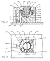
- Fig. 2 For example, the transmission unit 11 is shown in an assembled manner.
- the drive portion 24 of the adjustment shaft 23, the tread 30 'of the race member 29, the ball cage 27 with radially aligned transverse bores 28 and the guided in the transverse bores 28 and between the drive portion 24 and the tread 30' with light Pressure held balls 25 together form a reduction gear.
- the ball cage 27 comprises a cylindrical region in which the transverse bores 28 are arranged in the radial direction, preferably three bores.
- the ball cage 27 comprises Furthermore, a disc 35 with scale, which is shown as a continuous row of numbers, and a coupling element 36, in particular in the form of a screwdriver tip, for engaging in the driving slot 15 of the electrical component 12th
- a slot 22 serves as the simplest kind of an input means.
- the shaft 23 further comprises an annular groove 40, in which an elastic ring 41, for example, a commercial O-ring is inserted.
- the adjusting shaft 23 is rotatable with its O-ring 41 and, above all, mounted in a splash-proof manner in an opening 43 of the housing 21.
- This housing 21 has, in addition to the opening 43, a transparent region 44, above which a respective digit of the scale disk 35 is visible.
- the housing 21 has in its interior a support for the raceway element 29, which holds the tread 30 'rotationally fixed and elastic, orthogonal and centered to the adjusting shaft 23.
- the race member 29 has four spring portions 31, each with two spring legs 32 and a common tip 33.
- the legs 32 are bent outwardly concave. They open tangentially and thus flat in the race 30, while the legs 32 at the tips 33 enclose an angle of less than 90 °.
- This design results in relatively large spring areas and a good fixation in the rectangular inner edges of the housing unit 21.
- the dimensions are chosen so that the tips 33 flush with the edges so that in all spring legs 32 about the same spring Forces are built, the total burden the race 30 radially inward. This results a pressure that presses the balls 25 between the tread 30 'and the drive portion 24 a little, so that the balls with respect to these surfaces get a good, even over long periods and varying conditions, especially temperature change, evenly lasting frictional contact.
- both the drive region 24 and the running surface 30 ' are recessed in cross-section in the direction of the balls 25 in a concave manner. These recesses further enhance the overall integrity of the assembled gear unit 11.
- the adjusting shaft 23 is preferably made of metal, in particular for reasons of durability and stability.
- the balls 25 are made of metal, especially steel.
- the parts form ball cage 27, raceway element 29 and housing unit 21 injection molded parts made of electrically non-conductive plastic.
- gear unit 11 of such materials results in low production costs, long serviceability and, above all, a very considerable dielectric strength of several kilovolts, which corresponds to the EMC standards.
- this structure allows miniaturizing the gear unit to dimensions of about 1 x 1 x 1 cm and less.
- the housing unit 21 may be cylindrical, cubic or cubic with side lug 46 as through FIGS. 1 to 3 shown to be trained.
- a further transparent region can be arranged, via which and an adjacent light guide 47 the light emitted by the light emitting diodes 13, 14 can be detected.
- One option is also to provide a transparent plastic as the material of the housing unit 21.
- the housing unit 21 is open at the bottom and closed by a flat, continuous lower edge 49, with which it can rest flush on the module carrier 50 of the electrical component 12.
- the process of assembly is as follows: After fixing the electrical component 12 and possibly the light-emitting diodes 13, 14 on the assembly carrier 50, the assembled gear unit 11 is pushed over the component 12, that the coupling element 36 in engagement with the Slot 15 is coming. At the end of the assembly, the housing unit 21 lies with its lower edge 49 flat on the module carrier 50 and encloses the device 12 completely. In this position, the unit 11 is fixed on the carrier 50, for example by adhesive, by pins on the lower edge 49 and associated holes in the carrier 50 or by jamming with the device 12th
- the housing unit 21 may also be made integral with the housing of the instrument or apparatus in which the electrical / electronic components to be operated are installed.
- the gear unit is installed analogously as described above in this housing unit.
- the transmission unit 11 according to the invention fulfills all of the requirements mentioned above, in particular robustness, electrical voltage safety, ease of assembly, long-term capability even in harsh environments.
- gear unit 11 has no end stops. This makes it possible to utilize the full range of variation of the respective associated electrical / electronic component 12.
Landscapes
- Engineering & Computer Science (AREA)
- Microelectronics & Electronic Packaging (AREA)
- Gears, Cams (AREA)
- Friction Gearing (AREA)
- Gear Transmission (AREA)
- General Details Of Gearings (AREA)
- Input Circuits Of Receivers And Coupling Of Receivers And Audio Equipment (AREA)
- Transmitters (AREA)
- Radar Systems Or Details Thereof (AREA)
Description
- Die Erfindung betrifft eine Getriebe-Einheit für die Kombination mit einem manuell einstellbaren, elektrischen Bauelement mit einem Untersetzungsgetriebe, sowie die Verwendung derselben. Die abhängigen Ansprüche geben Ausgestaltungen der Erfindungen an.
- Untersetzungsgetriebe zum präziseren Einstellen von manuell betätigbaren, elektrisch/ elektronischen Geräten sind seit Jahrzehnten bekannt. So zeigt beispielsweise die
GB 550 234 von 1942 - Ein vergleichbares neueres Untersetzungsgetriebe der gleichen Art ist in der
US 3 951 001 von 1976 beschrieben. Bei diesem ist eine Schraubenfeder vorgesehen, die den Adhäsionsdruck zwischen den Kugeln und den Laufflächen vergrössert. - Eine Aufgabe der Erfindung besteht darin, eine Getriebe-Einheit unter Verwendung der genannten Art von Untersetzungsgetrieben anzugeben, die in zeitgemässer elektrisch/elektronischer Bauweise aufgebaut und dimensioniert ist und deren Ausmasse die Grösse von 1 x 1 x 1 cm nicht wesentlich überschreiten. Die Einheit soll weiter mit verschiedenen elektrisch/elektronischen Bauelementen problemlos kombinierbar sein und den EMC-Normen bezüglich Spannungsfestigkeit voll entsprechen.
- Eine solche Getriebe-Einheit wird durch den unabhängigen Anspruch 1 definiert. Diese Getriebe-Einheit bildet ein eigenständiges, mechanisches Bauelement, das zum Kombinieren mit Bauelementen auf Leiterplatten, insbesondere mit Drehpotentiometern geeignet ist.
- In einer bevorzugte Ausführung soll die Getriebe-Einheit robust und spritzwasserdicht und somit für rauhe Betriebsbedingungen geeignet sein. Dazu ist die Getriebe-Einheit gemäss Anspruch 2 mit einer Gehäuse-Einheit ausgerüstet, die einen robusten Schutz der inneren Bestandteile gegenüber allen äusseren Einflüssen darstellt. Weiter ist die Einheit gegenüber Stössen resistent, da sie keine Teile aufweist, die gegeneinander freies Spiel aufweisen.
- Im Folgenden wird die Erfindung anhand eines Ausführungsbeispiels näher beschrieben.
- Fig. 1
- zeigt eine perspektivische Explosions-Darstellung einer Getriebe-Einheit gemäss Erfindung;
- Fig. 2
- zeigt einen zentralen Querschnitt durch die zusammengebaute Getriebe-Einheit von
Figur 1 ; - Fig. 3
- zeigt eine Aufsicht auf die Getriebe-Einheit von
Figur 1 . -
Fig. 1 zeigt eine perspektivische Explosions-Darstellung der Getriebe-Einheit 11 und eines mit diesem gekoppelten elektrisch/elektronischen Bauelements 12, insbesondere eines Drehwiderstandes bzw. eines Drehpotentiometers. Dieses Bauelement 12 ist ausgebildet zur Montage auf einer ebenen, nicht gezeigten Leiterplatte, auf der weiter zwei Leuchtdioden (LED) 13, 14 montiert sein können. Das elektrische Bauelement 12 weist in seiner Verstell-Achse 16 zum Zweck einer manuellen Einstellbarkeit einen Schlitz 15 auf, in den beispielsweise ein Schraubendreher einschiebbar ist. - Die Getriebe-Einheit 11 umfasst vor allem eine Gehäuse-Einheit 21, eine Einstell-Welle 23, drei Kugeln 25, einen Kugelkäfig 27 und ein Laufring-Element 29.
- In
Fig. 2 wird die Getriebe-Einheit 11 in zusammengesetzter Weise gezeigt. Der Antriebs-Bereich 24 der Einstell-Welle 23, die Lauffläche 30' des Laufring-Elementes 29, der Kugelkäfig 27 mit radial ausgerichteten Querbohrungen 28 und die in den Querbohrungen 28 geführten und zwischen dem Antriebs-Bereich 24 und der Lauffläche 30' mit leichtem Druck gehaltenen Kugeln 25 bilden zusammen ein Untersetzungsgetriebe. - Der Kugelkäfig 27 umfasst einen zylindrischen Bereich, in dem in radialer Richtung die Querbohrungen 28 angeordnet sind, bevorzugt drei Bohrungen. Der Kugelkäfig 27 umfasst weiter eine Scheibe 35 mit Skala, die als fortlaufende Zahlenreihe dargestellt ist, und ein Kupplungs-Element 36, insbesondere in Form einer Schraubendreher-Spitze, zum Eingreifen in den Mitnahme-Schlitz 15 des elektrischen Bauelementes 12.
- Zum Drehen der Einstell-Welle 23 der Getriebe-Einheit 11 dient ein Schlitz 22 als einfachste Art eines Eingabe-Mittels. Die Welle 23 umfasst weiter eine Ringnut 40, in die ein elastischer Ring 41, beispielsweise ein handelsüblicher O-Ring, eingelegt ist.
- Die Einstell-Welle 23 ist mit ihrem O-Ring 41 drehbar und vor allem spritzwasserdicht in einer Öffnung 43 des Gehäuses 21 gelagert. Dieses Gehäuse 21 weist neben der Öffnung 43 einen transparenten Bereich 44 auf, über den jeweils eine Ziffer der Skalen-Scheibe 35 sichtbar ist.
- Das Gehäuse 21 weist in seinem Inneren eine Halterung für das Laufring-Element 29 auf, die die Lauffläche 30' drehfest und elastisch, orthogonal und mittig zur Einstell-Welle 23 ausgerichtet hält. Hierzu besitzt das Laufring-Element 29 vier Feder-Bereiche 31 mit jeweils zwei Feder-Schenkeln 32 und einer gemeinsamen Spitze 33. Die Schenkel 32 sind nach aussen konkav gebogen. Sie münden tangential und damit flach in den Laufring 30 ein, während die Schenkel 32 an den Spitzen 33 einen Winkel von weniger als 90° einschliessen.
- Durch diesen Aufbau ergeben sich relativ grosse Federbereiche und eine gute Fixierung in den rechteckigen Innenkanten der Gehäuse-Einheit 21. Die Dimensionierungen sind so gewählt, dass die Spitzen 33 bündig in den Kanten so anliegen, dass dabei in allen Feder-Schenkeln 32 etwa gleiche Feder-Kräfte aufgebaut werden, die gesamthaft den Laufring 30 radial nach innen belasten. Hierdurch entsteht ein Druck, der die Kugeln 25 zwischen die Lauffläche 30' und den Antriebs-Bereich 24 ein wenig einpresst, so dass die Kugeln gegenüber diesen Flächen einen guten, auch über lange Dauer und variierende Bedingungen, insbesondere TemperaturWechsel, gleichmässig anhaltenden Reibkontakt erhalten.
- Bei gewissen Ausführungen und Materialien kann es von Vorteil oder erforderlich sein, grössere Reibkräfte zwischen den Kugeln und Lauffläche zu erzeugen, z. B. dadurch, dass die Oberfläche der Kugeln bearbeitet, bzw. aufgerauht wird.
- Zur besseren Führung der Kugeln 25 sind sowohl der Antriebs-Bereich 24 als auch die Lauffläche 30' im Querschnitt jeweils in Richtung der Kugeln 25 konkav vertieft. Diese Vertiefungen verbessern weiter das gesamthafte Zusammenhalten der zusammengebauten Getriebe-Einheit 11.
- Die Einstell-Welle 23 ist bevorzugt aus Metall gefertigt, insbesondere aus Gründen der Haltbarkeit und Stabilität. Aus den gleichen Gründen bestehen auch die Kugeln 25 aus Metall, vor allem aus Stahl. Dem gegenüber bilden die Teile Kugelkäfig 27, Laufring-Element 29 und Gehäuse-Einheit 21 Spritzguss-Teile aus elektrisch nichtleitendem Kunststoff.
- Der Aufbau der Getriebe-Einheit 11 aus derartigen Materialien ergibt günstige Herstellungskosten, lange Gebrauchsfähigkeit und vor allem eine sehr erhebliche Spannungsfestigkeit von mehreren Kilovolt, die den Normen EMC entspricht. Ausserdem erlaubt dieser Aufbau ein Miniaturisieren der Getriebe-Einheit bis zu Dimensionen von etwa 1 x 1 x 1 cm und weniger.
- Die Gehäuse-Einheit 21 kann zylindrisch, kubisch oder kubisch mit Seitenansatz 46 wie durch die
Figuren 1 bis 3 gezeigt, ausgebildet sein. Bevorzugt weist die Gehäuse-Einheit 21 neben dem Ende der Einstell-Welle 23 und deren Schlitz 22 ein Sichtfenster 44 auf, durch das jeweils eine Ziffer der Skalen-Scheibe 35 sichtbar ist. - Neben diesem Sichtfenster 44 kann ein weiterer transparenter Bereich angeordnet sein, über den und einen angrenzenden Lichtleiter 47 das von den Leuchtdioden 13, 14 ausgestrahlte Licht erkennbar ist. Eine Option besteht auch darin, als Material der Gehäuse-Einheit 21 einen transparenten Kunststoff vorzusehen.
- Die Gehäuse-Einheit 21 ist unten offen und durch eine ebene, durchgehende Unterkante 49 abgeschlossen, mit der sie bündig auf dem Baugruppen-Träger 50 des elektrischen Bauelements 12 aufliegen kann.
- Der Vorgang der Montage ist folgender: Nach der Fixierung des elektrischen Bauelements 12 und eventuell der Leuchtdioden 13, 14 auf dem Baugruppen-Träger 50, wird die zusammengebaute Getriebe-Einheit 11 so über das Bauelement 12 geschoben, dass das Kupplungselement 36 in Eingriff mit dem Schlitz 15 kommt. Am Ende des Zusammenbaus liegt die Gehäuse-Einheit 21 mit ihrer Unterkante 49 plan auf dem Baugruppen-Träger 50 auf und umschliesst das Bauelement 12 vollständig. In dieser Lage wird die Einheit 11 auf dem Träger 50 fixiert, beispielsweise durch Klebstoff, durch Stifte an der Unterkante 49 und zugeordnete Bohrungen im Träger 50 oder durch Verklemmen mit dem Bauelement 12.
- Die Gehäuse-Einheit 21 kann jedoch auch integral mit dem Gehäuse des Instrumentes oder des Apparates gefertigt sein, in welches die zu bedienenden elektrischen/elektronischen Bauelemente eingebaut sind. In diesem Fall wird die Getriebe-Einheit analog wie weiter oben beschrieben in diese Gehäuse-Einheit eingebaut.
- Es sind eine grosse Zahl von Varianten zu der beschriebenen Getriebe-Einheit möglich. Im Folgenden werden einige dieser Varianten aufgezählt:
- Die Kugeln 25 können aus Glas, Saphir oder Keramikmaterial gefertigt sein. In diesem Fall erhöht sich die elektrische Durchschlagsfestigkeit.
- Die Einstell-Welle 23 kann aus Kunststoff gefertigt sein.
- Das Laufring-Element 29 kann aus getrenntem Laufring 30 und separatem Halte- und Federbereich 31 gebildet sein. Beispielsweise könnte dieser Bereich 31 aus Federstahl gebogen und auf den Laufring 30 aufgeschnappt sein. Weiter sind Varianten bei der Gestaltung und der Anzahl der Feder-Schenkel 32 und der Spitzen 33 möglich, wobei jedoch keine grundsätzlichen Verbesserungen gegenüber der beschriebenen Ausführung resultieren.
- Die Skalen-Scheibe 35 und ihre Ablesungsart kann variiert werden, beispielsweise durch eine Strichskala.
- Durch Variation der Dimensionen der Durchmesser von Antriebs-Bereich 24, von Laufring 30 und der Kugeln 25 ist das Untersetzungs-Verhältnis veränderbar. Es ist ohne weiteres ein Drehungs-Verhältnis von 4 : 1 erreichbar.
- Die drehbare Halterung der Einstell-Welle 23 in der LagerÖffnung 43 kann anders als mit Hilfe eines O-Rings 41 durchgeführt werden, beispielsweise durch eine Gleitlager-Hülse.
- Die erfindungsgemässe Getriebe-Einheit 11 erfüllt alle eingangs erwähnten Forderungen, insbesondere Robustheit, elektrische Spannungssicherheit, einfache Montierbarkeit, Langzeit-Tauglichkeit auch in rauher Umgebung.
- Ein weiterer Vorteil besteht darin, dass die Getriebe-Einheit 11 keine Endanschläge aufweist. Dies ermöglicht die Ausnutzung der vollen Variationsbreite des jeweils zugeordneten elektrisch/elektronischen Bauelements 12.
Claims (15)
- Getriebe-Einheit für die Verwendung mit einem manuell einstellbaren, elektrischen Bauelement (12) mit einer manuell bedienbaren Einstell-Welle (23) und einem Untersetzungsgetriebe mit einem drehbaren Kugelkäfig (27) und einer Mehrzahl von Kugeln (25) sowie einem Laufring-Element (29) mit einem laufring (30) und einem diesen aussen umfassenden Feder- und Halte-Bereich (31), der Gruppen aus jeweils zwei Feder-Schenkeln (32) aufweist, die (32) nach aussen konkav gebogen sind, die tangential in den Laufring (30) einmünden, und die (32) paarweise in jeweils einer Spitze (33) enden, deren (33) eingeschlossener Winkel deutlich kleiner ist als 90°.
- Getriebe-Einheit nach Anspruch 1, dadurch gekennzeichnet, dass sie eine Gehäuse-Einheit (21) mit U-förmigem Querschnitt aufweist, mit einer Lageröffnung (43) im U-Bogen zum Lagern der Einstell-Welle (23) und HalteElemente im Inneren zum Fixieren des Laufring-Elementes (29).
- Getriebe-Einheit nach Anspruch 2, dadurch gekenntzeichnet, dass zwischen der Einstell-Welle (23) und der Gehäuse-Einheit (21) ein Dichtmittel (41) angeordnet ist.
- Getriebe-Einheit nach Anspruch 1, dadurch gekennzeichnet, dass vier symmetrisch verteilte Gruppen aus jeweils zwei Feder-Schenkeln (32) vorgesehen sind, die mit dem Laufring (30) eine homogene Einheit bilden.
- Getriebe-Einheit nach Anspruch 1, dadurch gekennzeichnet, dass die Lauffläche (30') im Querschnitt konkav vertieft ist.
- Getriebe-Einheit nach Anspruch 1, dadurch gekennzeichnet, dass das Untersetzungsgetriebe einem drehbaren Antriebs-Bereich (24), eine feststehende Lauffläche (30.') und der drehbare Kugelkäfig (27) mit einem Kupplungselement (36) zur kraftschlüssigen Verbindung mit dem elektrischen Bauelement 12 ausgerüstet ist und die Kugeln (25) durch den Kugelkäfig (27) geführt werden und zwischen dem Antriebs-Bereich (24) und der Lauffläche (30) zweiseitig antreibend angeordnet sind,
- Getriebe-Einheit nach Anspruch 1, dadurch gekennzeichnet, dass das Laufring-Element (29) einen zentralen Laufring (30) mit nach innen gerichteter Lauffläche (30') aufweist.
- Getriebe-Einheit nach Anspruch 2, dadurch gekennzeichnet, dass die Gehäuse-Einheit (21) im Inneren vier rechtwinklige Eckkanten aufweist, in die das Laufring-Element (29) mit seinen Spitzen (33) bündig einschiebbar ist, wobei die Dimensionierungen so gewählt sind, dass sich dabei in den Feder-Schenkeln (32) eine Feder-Spannung aufbaut.
- Getriebe-Einheit nach Anspruch 2 mit Teilen aus Metall, Keramik oder Kunststoff, wobei die Einstell-Welle (23) vorzugsweise ein Metall-Teil ist und der Kugelkäfig (27), das Laufring-Element (29) und die Gehäuse-Einheit (21) vorzugsweise Spritzguss-Teile aus Kunststoff sind, um die elektrische Isolation zu gewährleisten.
- Getriebe-Einheit nach Anspruch 9, dadurch gekennzeichnet, dass die Gehäuse-Einheit (21) zumindest teilweise durchsichtig ist.
- Getriebe-Einheit (11) nach Anspruch 9, dadurch gekennzeichnet, dass die maximalen Dimensionen der Gehäuse-Einheit (21) in der Grössenordnung von 1 x 1 x 1 cm liegen.
- Getriebe-Einheit nach einem der Ansprüche 1 bis 11, dadurch gekennzeichnet, dass die Oberfläche der Kugeln (25) bearbeitet ist, um eine grössere Reibung zu erzielen.
- Verwendung der Getriebe-Einheit gemäss Anspruch 1, dadurch gekennzeichnet, dass nach Fixierung des manuell einstellbaren, elektrischen Bauelementes (12) auf einem elektronischen Baugruppenträger (50) die Getriebe-Einheit (11) so über das Bauelement (12) geschoben wird, dass sich das Kupplungselement (36) kraftschlüssig mit dem Bauelement (12) verbindet, und so weit, bis die Unterkanten (49) der Gehäuse-Einheit (21) bündig auf dem Baugruppenträger (50) aufliegen und sich durch ein Verbindungsmittel mit diesem starr verbinden.
- Verwendung der Getriebe-Einheit nach Anspruch 13, dadurch gekennzeichnet, dass das Verbindungsmittel ein Klebstoff ist.
- Verwendung der Getriebe-Einheit nach Anspruch 13, dadurch gekennzeichnet, dass das verbindungsmittel als Zapfen an den Unterkanten (49) der Gehäuse-Einheit (21) und zugeordnete Bohrungen am Baugruppenträger (50) ausgebildet sind..
Priority Applications (6)
| Application Number | Priority Date | Filing Date | Title |
|---|---|---|---|
| DE502007002252T DE502007002252D1 (de) | 2007-01-15 | 2007-01-15 | Getriebe-Einheit und Verwendung derselben |
| EP07405011A EP1944776B1 (de) | 2007-01-15 | 2007-01-15 | Getriebe-Einheit und Verwendung derselben |
| AT07405011T ATE451702T1 (de) | 2007-01-15 | 2007-01-15 | Getriebe-einheit und verwendung derselben |
| US11/966,173 US8192319B2 (en) | 2007-01-15 | 2007-12-28 | Gear unit and use of the same |
| CN2008100031428A CN101225875B (zh) | 2007-01-15 | 2008-01-10 | 齿轮组及其安装方法 |
| JP2008003860A JP5290583B2 (ja) | 2007-01-15 | 2008-01-11 | ギヤ・ユニット及びその使用 |
Applications Claiming Priority (1)
| Application Number | Priority Date | Filing Date | Title |
|---|---|---|---|
| EP07405011A EP1944776B1 (de) | 2007-01-15 | 2007-01-15 | Getriebe-Einheit und Verwendung derselben |
Publications (2)
| Publication Number | Publication Date |
|---|---|
| EP1944776A1 EP1944776A1 (de) | 2008-07-16 |
| EP1944776B1 true EP1944776B1 (de) | 2009-12-09 |
Family
ID=38123963
Family Applications (1)
| Application Number | Title | Priority Date | Filing Date |
|---|---|---|---|
| EP07405011A Not-in-force EP1944776B1 (de) | 2007-01-15 | 2007-01-15 | Getriebe-Einheit und Verwendung derselben |
Country Status (6)
| Country | Link |
|---|---|
| US (1) | US8192319B2 (de) |
| EP (1) | EP1944776B1 (de) |
| JP (1) | JP5290583B2 (de) |
| CN (1) | CN101225875B (de) |
| AT (1) | ATE451702T1 (de) |
| DE (1) | DE502007002252D1 (de) |
Families Citing this family (8)
| Publication number | Priority date | Publication date | Assignee | Title |
|---|---|---|---|---|
| US10598429B2 (en) * | 2012-12-14 | 2020-03-24 | Arcelik Anonim Sirketi | Cooling device comprising of a knob providing the adjustment of the compartment temperature |
| DE102014216389A1 (de) * | 2014-08-19 | 2016-02-25 | BSH Hausgeräte GmbH | Bedienvorrichtung für ein Haushaltsgerät mit stabil positioniertem ringförmigen Bedienelement-Vorderteil und Haushaltsgerät mit einer derartigen Bedienvorrichtung |
| US9631700B2 (en) | 2015-05-13 | 2017-04-25 | Whirlpool Corporation | Multi-function appliance knob incorporating multiple rotation modulating mechanisms |
| US9556939B2 (en) | 2015-05-13 | 2017-01-31 | Whirlpool Corporation | Multi-function appliance knob incorporating multiple rotation modulating mechanisms |
| USD806512S1 (en) | 2016-12-22 | 2018-01-02 | Whirlpool Corporation | Knob |
| USD824237S1 (en) | 2016-12-28 | 2018-07-31 | Whirlpool Corporation | Knob |
| USD808243S1 (en) | 2016-12-28 | 2018-01-23 | Whirlpool Corporation | Knob |
| US11458605B2 (en) * | 2018-03-28 | 2022-10-04 | Graco Minnesota Inc. | Packing insertion tool for paint and other fluid pumps |
Family Cites Families (12)
| Publication number | Priority date | Publication date | Assignee | Title |
|---|---|---|---|---|
| US2289066A (en) * | 1940-01-04 | 1942-07-07 | Illinois Tool Works | Fastener unit |
| GB550234A (en) * | 1941-06-27 | 1942-12-30 | Automatic Telephone & Elect | Improvements in epicyclic gearing suitable for the control of adjustable condensers |
| US2935714A (en) * | 1958-04-25 | 1960-05-03 | Chicago Telephone Supply Corp | Variable resistor with vernier control |
| JPS49105864U (de) * | 1972-12-29 | 1974-09-11 | ||
| US3951001A (en) * | 1974-05-21 | 1976-04-20 | Takayoshi Saito | Vernier drive mechanism |
| US4032880A (en) * | 1976-03-08 | 1977-06-28 | Drestech Corporation | Electrical device |
| JPS57173654A (en) * | 1981-04-21 | 1982-10-26 | Noiberuku Kk | Transmission |
| JPS59159028U (ja) * | 1983-04-11 | 1984-10-25 | 株式会社村田製作所 | Uhfチユ−ナ装置 |
| US4711434A (en) * | 1986-07-07 | 1987-12-08 | Haag Donald L | Spring disc |
| JPH0663953U (ja) * | 1993-02-19 | 1994-09-09 | エヌ・オー・ケー・メグラスティック株式会社 | 防振ブッシュ |
| DE19720543C1 (de) * | 1997-05-16 | 1998-05-20 | Preh Elektro Feinmechanik | Elektrischer Drehwiderstand |
| JP3659925B2 (ja) * | 2002-03-25 | 2005-06-15 | 三菱重工業株式会社 | マイクロトラクションドライブ |
-
2007
- 2007-01-15 DE DE502007002252T patent/DE502007002252D1/de active Active
- 2007-01-15 EP EP07405011A patent/EP1944776B1/de not_active Not-in-force
- 2007-01-15 AT AT07405011T patent/ATE451702T1/de active
- 2007-12-28 US US11/966,173 patent/US8192319B2/en not_active Expired - Fee Related
-
2008
- 2008-01-10 CN CN2008100031428A patent/CN101225875B/zh not_active Expired - Fee Related
- 2008-01-11 JP JP2008003860A patent/JP5290583B2/ja not_active Expired - Fee Related
Also Published As
| Publication number | Publication date |
|---|---|
| US8192319B2 (en) | 2012-06-05 |
| DE502007002252D1 (de) | 2010-01-21 |
| JP2008170007A (ja) | 2008-07-24 |
| CN101225875A (zh) | 2008-07-23 |
| JP5290583B2 (ja) | 2013-09-18 |
| CN101225875B (zh) | 2012-02-01 |
| EP1944776A1 (de) | 2008-07-16 |
| ATE451702T1 (de) | 2009-12-15 |
| US20080261744A1 (en) | 2008-10-23 |
Similar Documents
| Publication | Publication Date | Title |
|---|---|---|
| EP1944776A1 (de) | Getriebe-Einheit und Verwendung derselben | |
| DE2035719C3 (de) | Drehknopf | |
| DE2117276B2 (de) | Einstellbarer Drehwiderstand | |
| EP3618087B1 (de) | Elektrischer schalter | |
| DE2812332C3 (de) | Vielfachsteckverbindung für Karten mit gedruckter Schaltung | |
| DE102005032509A1 (de) | Bedienelement | |
| EP0902448A2 (de) | Elektrisches Installationsgerät, insbesondere Taster, Steller oder Schalter | |
| DE1908661A1 (de) | Verfahren zur Herstellung eines Potentiometers sowie nach diesem Verfahren hergestelltes Potentiometers | |
| DE2940515C2 (de) | Meßgerät | |
| DE2218980C3 (de) | Schalter-Helligkeitssteller-Kombination | |
| DE2831204B1 (de) | Miniatur-Stufenschalter | |
| DE3511600A1 (de) | Schiebeschalter | |
| DE202011051616U1 (de) | Eine LED-Innenleuchte | |
| DE1665310A1 (de) | Potentiometer | |
| WO2009080402A1 (de) | Gehäuse mit einer darin angeordneten baugruppe | |
| DE2823285A1 (de) | Einstellbarer drehwiderstand | |
| EP0044542A2 (de) | Messinstrumentengehäuse | |
| EP0160796A1 (de) | Schalteranordnung | |
| DE202023104439U1 (de) | Leuchtender Drehknopf | |
| DE10031748A1 (de) | Hohlkörper für die Elektroinstallation | |
| DE2954393C2 (de) | Stufendrehschalter für analoge Vielfachmeßgeräte | |
| DE2609166B2 (de) | Elektrische Einstelleinrichtung | |
| DE10226766A1 (de) | Antriebsvorrichtung | |
| EP4258307A1 (de) | Gerät der hausinstallationstechnik | |
| DE3139094A1 (de) | Anzeigevorrichtung fuer einen veraenderbaren widerstand |
Legal Events
| Date | Code | Title | Description |
|---|---|---|---|
| PUAI | Public reference made under article 153(3) epc to a published international application that has entered the european phase |
Free format text: ORIGINAL CODE: 0009012 |
|
| AK | Designated contracting states |
Kind code of ref document: A1 Designated state(s): AT BE BG CH CY CZ DE DK EE ES FI FR GB GR HU IE IS IT LI LT LU LV MC NL PL PT RO SE SI SK TR |
|
| AX | Request for extension of the european patent |
Extension state: AL BA HR MK RS |
|
| 17P | Request for examination filed |
Effective date: 20081212 |
|
| 17Q | First examination report despatched |
Effective date: 20090210 |
|
| AKX | Designation fees paid |
Designated state(s): AT BE BG CH CY CZ DE DK EE ES FI FR GB GR HU IE IS IT LI LT LU LV MC NL PL PT RO SE SI SK TR |
|
| GRAP | Despatch of communication of intention to grant a patent |
Free format text: ORIGINAL CODE: EPIDOSNIGR1 |
|
| GRAS | Grant fee paid |
Free format text: ORIGINAL CODE: EPIDOSNIGR3 |
|
| GRAA | (expected) grant |
Free format text: ORIGINAL CODE: 0009210 |
|
| AK | Designated contracting states |
Kind code of ref document: B1 Designated state(s): AT BE BG CH CY CZ DE DK EE ES FI FR GB GR HU IE IS IT LI LT LU LV MC NL PL PT RO SE SI SK TR |
|
| REG | Reference to a national code |
Ref country code: GB Ref legal event code: FG4D Free format text: NOT ENGLISH |
|
| REG | Reference to a national code |
Ref country code: CH Ref legal event code: EP |
|
| REG | Reference to a national code |
Ref country code: IE Ref legal event code: FG4D |
|
| REF | Corresponds to: |
Ref document number: 502007002252 Country of ref document: DE Date of ref document: 20100121 Kind code of ref document: P |
|
| REG | Reference to a national code |
Ref country code: NL Ref legal event code: VDEP Effective date: 20091209 |
|
| PG25 | Lapsed in a contracting state [announced via postgrant information from national office to epo] |
Ref country code: LT Free format text: LAPSE BECAUSE OF FAILURE TO SUBMIT A TRANSLATION OF THE DESCRIPTION OR TO PAY THE FEE WITHIN THE PRESCRIBED TIME-LIMIT Effective date: 20091209 Ref country code: FI Free format text: LAPSE BECAUSE OF FAILURE TO SUBMIT A TRANSLATION OF THE DESCRIPTION OR TO PAY THE FEE WITHIN THE PRESCRIBED TIME-LIMIT Effective date: 20091209 Ref country code: SE Free format text: LAPSE BECAUSE OF FAILURE TO SUBMIT A TRANSLATION OF THE DESCRIPTION OR TO PAY THE FEE WITHIN THE PRESCRIBED TIME-LIMIT Effective date: 20091209 |
|
| LTIE | Lt: invalidation of european patent or patent extension |
Effective date: 20091209 |
|
| PG25 | Lapsed in a contracting state [announced via postgrant information from national office to epo] |
Ref country code: LV Free format text: LAPSE BECAUSE OF FAILURE TO SUBMIT A TRANSLATION OF THE DESCRIPTION OR TO PAY THE FEE WITHIN THE PRESCRIBED TIME-LIMIT Effective date: 20091209 Ref country code: SI Free format text: LAPSE BECAUSE OF FAILURE TO SUBMIT A TRANSLATION OF THE DESCRIPTION OR TO PAY THE FEE WITHIN THE PRESCRIBED TIME-LIMIT Effective date: 20091209 Ref country code: PL Free format text: LAPSE BECAUSE OF FAILURE TO SUBMIT A TRANSLATION OF THE DESCRIPTION OR TO PAY THE FEE WITHIN THE PRESCRIBED TIME-LIMIT Effective date: 20091209 |
|
| REG | Reference to a national code |
Ref country code: IE Ref legal event code: FD4D |
|
| PG25 | Lapsed in a contracting state [announced via postgrant information from national office to epo] |
Ref country code: PT Free format text: LAPSE BECAUSE OF FAILURE TO SUBMIT A TRANSLATION OF THE DESCRIPTION OR TO PAY THE FEE WITHIN THE PRESCRIBED TIME-LIMIT Effective date: 20100409 Ref country code: EE Free format text: LAPSE BECAUSE OF FAILURE TO SUBMIT A TRANSLATION OF THE DESCRIPTION OR TO PAY THE FEE WITHIN THE PRESCRIBED TIME-LIMIT Effective date: 20091209 Ref country code: ES Free format text: LAPSE BECAUSE OF FAILURE TO SUBMIT A TRANSLATION OF THE DESCRIPTION OR TO PAY THE FEE WITHIN THE PRESCRIBED TIME-LIMIT Effective date: 20100320 Ref country code: IE Free format text: LAPSE BECAUSE OF FAILURE TO SUBMIT A TRANSLATION OF THE DESCRIPTION OR TO PAY THE FEE WITHIN THE PRESCRIBED TIME-LIMIT Effective date: 20091209 Ref country code: IS Free format text: LAPSE BECAUSE OF FAILURE TO SUBMIT A TRANSLATION OF THE DESCRIPTION OR TO PAY THE FEE WITHIN THE PRESCRIBED TIME-LIMIT Effective date: 20100409 Ref country code: BG Free format text: LAPSE BECAUSE OF FAILURE TO SUBMIT A TRANSLATION OF THE DESCRIPTION OR TO PAY THE FEE WITHIN THE PRESCRIBED TIME-LIMIT Effective date: 20100309 Ref country code: RO Free format text: LAPSE BECAUSE OF FAILURE TO SUBMIT A TRANSLATION OF THE DESCRIPTION OR TO PAY THE FEE WITHIN THE PRESCRIBED TIME-LIMIT Effective date: 20091209 Ref country code: NL Free format text: LAPSE BECAUSE OF FAILURE TO SUBMIT A TRANSLATION OF THE DESCRIPTION OR TO PAY THE FEE WITHIN THE PRESCRIBED TIME-LIMIT Effective date: 20091209 |
|
| BERE | Be: lapsed |
Owner name: OPTOSYS SA Effective date: 20100131 |
|
| PG25 | Lapsed in a contracting state [announced via postgrant information from national office to epo] |
Ref country code: MC Free format text: LAPSE BECAUSE OF NON-PAYMENT OF DUE FEES Effective date: 20100131 Ref country code: SK Free format text: LAPSE BECAUSE OF FAILURE TO SUBMIT A TRANSLATION OF THE DESCRIPTION OR TO PAY THE FEE WITHIN THE PRESCRIBED TIME-LIMIT Effective date: 20091209 Ref country code: CZ Free format text: LAPSE BECAUSE OF FAILURE TO SUBMIT A TRANSLATION OF THE DESCRIPTION OR TO PAY THE FEE WITHIN THE PRESCRIBED TIME-LIMIT Effective date: 20091209 |
|
| PLBE | No opposition filed within time limit |
Free format text: ORIGINAL CODE: 0009261 |
|
| STAA | Information on the status of an ep patent application or granted ep patent |
Free format text: STATUS: NO OPPOSITION FILED WITHIN TIME LIMIT |
|
| REG | Reference to a national code |
Ref country code: FR Ref legal event code: ST Effective date: 20100930 |
|
| PG25 | Lapsed in a contracting state [announced via postgrant information from national office to epo] |
Ref country code: FR Free format text: LAPSE BECAUSE OF NON-PAYMENT OF DUE FEES Effective date: 20100209 Ref country code: GR Free format text: LAPSE BECAUSE OF FAILURE TO SUBMIT A TRANSLATION OF THE DESCRIPTION OR TO PAY THE FEE WITHIN THE PRESCRIBED TIME-LIMIT Effective date: 20100310 Ref country code: CY Free format text: LAPSE BECAUSE OF FAILURE TO SUBMIT A TRANSLATION OF THE DESCRIPTION OR TO PAY THE FEE WITHIN THE PRESCRIBED TIME-LIMIT Effective date: 20091209 |
|
| 26N | No opposition filed |
Effective date: 20100910 |
|
| PG25 | Lapsed in a contracting state [announced via postgrant information from national office to epo] |
Ref country code: DK Free format text: LAPSE BECAUSE OF FAILURE TO SUBMIT A TRANSLATION OF THE DESCRIPTION OR TO PAY THE FEE WITHIN THE PRESCRIBED TIME-LIMIT Effective date: 20091209 |
|
| PG25 | Lapsed in a contracting state [announced via postgrant information from national office to epo] |
Ref country code: BE Free format text: LAPSE BECAUSE OF NON-PAYMENT OF DUE FEES Effective date: 20100131 |
|
| PG25 | Lapsed in a contracting state [announced via postgrant information from national office to epo] |
Ref country code: IT Free format text: LAPSE BECAUSE OF FAILURE TO SUBMIT A TRANSLATION OF THE DESCRIPTION OR TO PAY THE FEE WITHIN THE PRESCRIBED TIME-LIMIT Effective date: 20091209 |
|
| REG | Reference to a national code |
Ref country code: CH Ref legal event code: PL |
|
| GBPC | Gb: european patent ceased through non-payment of renewal fee |
Effective date: 20110115 |
|
| PG25 | Lapsed in a contracting state [announced via postgrant information from national office to epo] |
Ref country code: CH Free format text: LAPSE BECAUSE OF NON-PAYMENT OF DUE FEES Effective date: 20110131 Ref country code: LI Free format text: LAPSE BECAUSE OF NON-PAYMENT OF DUE FEES Effective date: 20110131 |
|
| PG25 | Lapsed in a contracting state [announced via postgrant information from national office to epo] |
Ref country code: GB Free format text: LAPSE BECAUSE OF NON-PAYMENT OF DUE FEES Effective date: 20110115 |
|
| PG25 | Lapsed in a contracting state [announced via postgrant information from national office to epo] |
Ref country code: HU Free format text: LAPSE BECAUSE OF FAILURE TO SUBMIT A TRANSLATION OF THE DESCRIPTION OR TO PAY THE FEE WITHIN THE PRESCRIBED TIME-LIMIT Effective date: 20100610 Ref country code: LU Free format text: LAPSE BECAUSE OF NON-PAYMENT OF DUE FEES Effective date: 20100115 |
|
| PG25 | Lapsed in a contracting state [announced via postgrant information from national office to epo] |
Ref country code: TR Free format text: LAPSE BECAUSE OF FAILURE TO SUBMIT A TRANSLATION OF THE DESCRIPTION OR TO PAY THE FEE WITHIN THE PRESCRIBED TIME-LIMIT Effective date: 20091209 |
|
| REG | Reference to a national code |
Ref country code: AT Ref legal event code: MM01 Ref document number: 451702 Country of ref document: AT Kind code of ref document: T Effective date: 20120115 |
|
| PG25 | Lapsed in a contracting state [announced via postgrant information from national office to epo] |
Ref country code: AT Free format text: LAPSE BECAUSE OF NON-PAYMENT OF DUE FEES Effective date: 20120115 |
|
| PGFP | Annual fee paid to national office [announced via postgrant information from national office to epo] |
Ref country code: DE Payment date: 20190123 Year of fee payment: 13 |
|
| PGFP | Annual fee paid to national office [announced via postgrant information from national office to epo] |
Ref country code: DE Payment date: 20190123 Year of fee payment: 13 |
|
| REG | Reference to a national code |
Ref country code: DE Ref legal event code: R119 Ref document number: 502007002252 Country of ref document: DE |
|
| PG25 | Lapsed in a contracting state [announced via postgrant information from national office to epo] |
Ref country code: DE Free format text: LAPSE BECAUSE OF NON-PAYMENT OF DUE FEES Effective date: 20200801 |