EP1944082A1 - Exhaust gas purifying catalyst and producing method thereof - Google Patents
Exhaust gas purifying catalyst and producing method thereof Download PDFInfo
- Publication number
- EP1944082A1 EP1944082A1 EP08000180A EP08000180A EP1944082A1 EP 1944082 A1 EP1944082 A1 EP 1944082A1 EP 08000180 A EP08000180 A EP 08000180A EP 08000180 A EP08000180 A EP 08000180A EP 1944082 A1 EP1944082 A1 EP 1944082A1
- Authority
- EP
- European Patent Office
- Prior art keywords
- catalyst
- oxides
- noble metal
- exhaust gas
- compounds
- Prior art date
- Legal status (The legal status is an assumption and is not a legal conclusion. Google has not performed a legal analysis and makes no representation as to the accuracy of the status listed.)
- Granted
Links
- 239000003054 catalyst Substances 0.000 title claims abstract description 284
- 238000000034 method Methods 0.000 title claims description 22
- 229910000510 noble metal Inorganic materials 0.000 claims abstract description 119
- 239000000843 powder Substances 0.000 claims abstract description 104
- 150000001875 compounds Chemical class 0.000 claims abstract description 101
- 239000002245 particle Substances 0.000 claims abstract description 66
- 230000003197 catalytic effect Effects 0.000 claims abstract description 8
- 229910052783 alkali metal Inorganic materials 0.000 claims abstract description 6
- 150000001340 alkali metals Chemical class 0.000 claims abstract description 6
- 229910052784 alkaline earth metal Inorganic materials 0.000 claims abstract description 6
- 229910052761 rare earth metal Inorganic materials 0.000 claims abstract description 6
- 230000007704 transition Effects 0.000 claims abstract description 6
- 239000010410 layer Substances 0.000 claims description 59
- 239000002994 raw material Substances 0.000 claims description 35
- 229910001593 boehmite Inorganic materials 0.000 claims description 26
- FAHBNUUHRFUEAI-UHFFFAOYSA-M hydroxidooxidoaluminium Chemical compound O[Al]=O FAHBNUUHRFUEAI-UHFFFAOYSA-M 0.000 claims description 26
- 229910052684 Cerium Inorganic materials 0.000 claims description 23
- 229910052726 zirconium Inorganic materials 0.000 claims description 23
- 238000010304 firing Methods 0.000 claims description 16
- 229910052746 lanthanum Inorganic materials 0.000 claims description 13
- 229910052748 manganese Inorganic materials 0.000 claims description 13
- 229910052742 iron Inorganic materials 0.000 claims description 12
- 229910052759 nickel Inorganic materials 0.000 claims description 12
- 239000000463 material Substances 0.000 claims description 11
- 239000002344 surface layer Substances 0.000 claims description 10
- BVKZGUZCCUSVTD-UHFFFAOYSA-L Carbonate Chemical compound [O-]C([O-])=O BVKZGUZCCUSVTD-UHFFFAOYSA-L 0.000 claims description 8
- 229910052788 barium Inorganic materials 0.000 claims description 8
- 229910052792 caesium Inorganic materials 0.000 claims description 8
- 229910052700 potassium Inorganic materials 0.000 claims description 8
- 229910052708 sodium Inorganic materials 0.000 claims description 8
- QAOWNCQODCNURD-UHFFFAOYSA-L Sulfate Chemical compound [O-]S([O-])(=O)=O QAOWNCQODCNURD-UHFFFAOYSA-L 0.000 claims description 7
- 239000000203 mixture Substances 0.000 claims description 6
- 230000000536 complexating effect Effects 0.000 claims description 4
- 230000009970 fire resistant effect Effects 0.000 claims description 4
- 150000007529 inorganic bases Chemical class 0.000 claims 2
- 229910000422 cerium(IV) oxide Inorganic materials 0.000 description 63
- CETPSERCERDGAM-UHFFFAOYSA-N ceric oxide Chemical compound O=[Ce]=O CETPSERCERDGAM-UHFFFAOYSA-N 0.000 description 62
- 239000002923 metal particle Substances 0.000 description 59
- BASFCYQUMIYNBI-UHFFFAOYSA-N platinum Chemical compound [Pt] BASFCYQUMIYNBI-UHFFFAOYSA-N 0.000 description 53
- MCMNRKCIXSYSNV-UHFFFAOYSA-N Zirconium dioxide Chemical compound O=[Zr]=O MCMNRKCIXSYSNV-UHFFFAOYSA-N 0.000 description 52
- 239000007789 gas Substances 0.000 description 43
- 229910002651 NO3 Inorganic materials 0.000 description 42
- NHNBFGGVMKEFGY-UHFFFAOYSA-N Nitrate Chemical compound [O-][N+]([O-])=O NHNBFGGVMKEFGY-UHFFFAOYSA-N 0.000 description 42
- 238000006243 chemical reaction Methods 0.000 description 40
- 230000000694 effects Effects 0.000 description 35
- MWUXSHHQAYIFBG-UHFFFAOYSA-N Nitric oxide Chemical compound O=[N] MWUXSHHQAYIFBG-UHFFFAOYSA-N 0.000 description 30
- XLYOFNOQVPJJNP-UHFFFAOYSA-N water Substances O XLYOFNOQVPJJNP-UHFFFAOYSA-N 0.000 description 30
- 229910001868 water Inorganic materials 0.000 description 30
- 239000002002 slurry Substances 0.000 description 24
- 238000001035 drying Methods 0.000 description 19
- 229910052723 transition metal Inorganic materials 0.000 description 14
- 150000003624 transition metals Chemical class 0.000 description 14
- UGFAIRIUMAVXCW-UHFFFAOYSA-N Carbon monoxide Chemical compound [O+]#[C-] UGFAIRIUMAVXCW-UHFFFAOYSA-N 0.000 description 13
- GRYLNZFGIOXLOG-UHFFFAOYSA-N Nitric acid Chemical compound O[N+]([O-])=O GRYLNZFGIOXLOG-UHFFFAOYSA-N 0.000 description 13
- 229910002091 carbon monoxide Inorganic materials 0.000 description 13
- 150000002430 hydrocarbons Chemical class 0.000 description 13
- 239000011572 manganese Substances 0.000 description 13
- 229910017604 nitric acid Inorganic materials 0.000 description 13
- MRELNEQAGSRDBK-UHFFFAOYSA-N lanthanum oxide Inorganic materials [O-2].[O-2].[O-2].[La+3].[La+3] MRELNEQAGSRDBK-UHFFFAOYSA-N 0.000 description 12
- 239000007788 liquid Substances 0.000 description 12
- KTUFCUMIWABKDW-UHFFFAOYSA-N oxo(oxolanthaniooxy)lanthanum Chemical compound O=[La]O[La]=O KTUFCUMIWABKDW-UHFFFAOYSA-N 0.000 description 12
- PNEYBMLMFCGWSK-UHFFFAOYSA-N aluminium oxide Inorganic materials [O-2].[O-2].[O-2].[Al+3].[Al+3] PNEYBMLMFCGWSK-UHFFFAOYSA-N 0.000 description 11
- 238000002156 mixing Methods 0.000 description 10
- 239000000243 solution Substances 0.000 description 10
- 229910052878 cordierite Inorganic materials 0.000 description 9
- JSKIRARMQDRGJZ-UHFFFAOYSA-N dimagnesium dioxido-bis[(1-oxido-3-oxo-2,4,6,8,9-pentaoxa-1,3-disila-5,7-dialuminabicyclo[3.3.1]nonan-7-yl)oxy]silane Chemical compound [Mg++].[Mg++].[O-][Si]([O-])(O[Al]1O[Al]2O[Si](=O)O[Si]([O-])(O1)O2)O[Al]1O[Al]2O[Si](=O)O[Si]([O-])(O1)O2 JSKIRARMQDRGJZ-UHFFFAOYSA-N 0.000 description 9
- QTBSBXVTEAMEQO-UHFFFAOYSA-M Acetate Chemical compound CC([O-])=O QTBSBXVTEAMEQO-UHFFFAOYSA-M 0.000 description 8
- TZCXTZWJZNENPQ-UHFFFAOYSA-L barium sulfate Chemical compound [Ba+2].[O-]S([O-])(=O)=O TZCXTZWJZNENPQ-UHFFFAOYSA-L 0.000 description 8
- 230000015271 coagulation Effects 0.000 description 8
- 238000005345 coagulation Methods 0.000 description 8
- JEIPFZHSYJVQDO-UHFFFAOYSA-N iron(III) oxide Inorganic materials O=[Fe]O[Fe]=O JEIPFZHSYJVQDO-UHFFFAOYSA-N 0.000 description 8
- 238000003801 milling Methods 0.000 description 8
- GNMQOUGYKPVJRR-UHFFFAOYSA-N nickel(III) oxide Inorganic materials [O-2].[O-2].[O-2].[Ni+3].[Ni+3] GNMQOUGYKPVJRR-UHFFFAOYSA-N 0.000 description 8
- PZFKDUMHDHEBLD-UHFFFAOYSA-N oxo(oxonickeliooxy)nickel Chemical compound O=[Ni]O[Ni]=O PZFKDUMHDHEBLD-UHFFFAOYSA-N 0.000 description 8
- 239000000470 constituent Substances 0.000 description 6
- 230000000052 comparative effect Effects 0.000 description 5
- 230000002708 enhancing effect Effects 0.000 description 5
- 238000005470 impregnation Methods 0.000 description 5
- KOPBYBDAPCDYFK-UHFFFAOYSA-N Cs2O Inorganic materials [O-2].[Cs+].[Cs+] KOPBYBDAPCDYFK-UHFFFAOYSA-N 0.000 description 4
- KKCBUQHMOMHUOY-UHFFFAOYSA-N Na2O Inorganic materials [O-2].[Na+].[Na+] KKCBUQHMOMHUOY-UHFFFAOYSA-N 0.000 description 4
- QVGXLLKOCUKJST-UHFFFAOYSA-N atomic oxygen Chemical compound [O] QVGXLLKOCUKJST-UHFFFAOYSA-N 0.000 description 4
- AKUNKIJLSDQFLS-UHFFFAOYSA-M dicesium;hydroxide Chemical compound [OH-].[Cs+].[Cs+] AKUNKIJLSDQFLS-UHFFFAOYSA-M 0.000 description 4
- GEYXPJBPASPPLI-UHFFFAOYSA-N manganese(III) oxide Inorganic materials O=[Mn]O[Mn]=O GEYXPJBPASPPLI-UHFFFAOYSA-N 0.000 description 4
- 239000001301 oxygen Substances 0.000 description 4
- 229910052760 oxygen Inorganic materials 0.000 description 4
- 238000003860 storage Methods 0.000 description 4
- 239000000969 carrier Substances 0.000 description 3
- 230000014509 gene expression Effects 0.000 description 3
- 238000004519 manufacturing process Methods 0.000 description 3
- 239000011859 microparticle Substances 0.000 description 3
- 229910016341 Al2O3 ZrO2 Inorganic materials 0.000 description 2
- 239000002585 base Substances 0.000 description 2
- 230000008901 benefit Effects 0.000 description 2
- 238000004364 calculation method Methods 0.000 description 2
- 150000004649 carbonic acid derivatives Chemical class 0.000 description 2
- 238000002485 combustion reaction Methods 0.000 description 2
- 238000006073 displacement reaction Methods 0.000 description 2
- 229910010272 inorganic material Inorganic materials 0.000 description 2
- 239000011147 inorganic material Substances 0.000 description 2
- 229910044991 metal oxide Inorganic materials 0.000 description 2
- 150000004706 metal oxides Chemical class 0.000 description 2
- 238000001179 sorption measurement Methods 0.000 description 2
- 150000003467 sulfuric acid derivatives Chemical class 0.000 description 2
- 150000003623 transition metal compounds Chemical class 0.000 description 2
- UXHQLGLGLZKHTC-CUNXSJBXSA-N 4-[(3s,3ar)-3-cyclopentyl-7-(4-hydroxypiperidine-1-carbonyl)-3,3a,4,5-tetrahydropyrazolo[3,4-f]quinolin-2-yl]-2-chlorobenzonitrile Chemical compound C1CC(O)CCN1C(=O)C1=CC=C(C=2[C@@H]([C@H](C3CCCC3)N(N=2)C=2C=C(Cl)C(C#N)=CC=2)CC2)C2=N1 UXHQLGLGLZKHTC-CUNXSJBXSA-N 0.000 description 1
- 229910016010 BaAl2 Inorganic materials 0.000 description 1
- PWHULOQIROXLJO-UHFFFAOYSA-N Manganese Chemical compound [Mn] PWHULOQIROXLJO-UHFFFAOYSA-N 0.000 description 1
- GWXLDORMOJMVQZ-UHFFFAOYSA-N cerium Chemical compound [Ce] GWXLDORMOJMVQZ-UHFFFAOYSA-N 0.000 description 1
- 238000009792 diffusion process Methods 0.000 description 1
- 238000005516 engineering process Methods 0.000 description 1
- 239000011817 metal compound particle Substances 0.000 description 1
- 239000000693 micelle Substances 0.000 description 1
- 239000011259 mixed solution Substances 0.000 description 1
- 239000003960 organic solvent Substances 0.000 description 1
- 229910052763 palladium Inorganic materials 0.000 description 1
- 229910052697 platinum Inorganic materials 0.000 description 1
- 231100000614 poison Toxicity 0.000 description 1
- 231100000572 poisoning Toxicity 0.000 description 1
- 230000000607 poisoning effect Effects 0.000 description 1
- 229910052703 rhodium Inorganic materials 0.000 description 1
- 239000002356 single layer Substances 0.000 description 1
- 239000000126 substance Substances 0.000 description 1
- 239000003440 toxic substance Substances 0.000 description 1
Images

Classifications
-
- F—MECHANICAL ENGINEERING; LIGHTING; HEATING; WEAPONS; BLASTING
- F01—MACHINES OR ENGINES IN GENERAL; ENGINE PLANTS IN GENERAL; STEAM ENGINES
- F01N—GAS-FLOW SILENCERS OR EXHAUST APPARATUS FOR MACHINES OR ENGINES IN GENERAL; GAS-FLOW SILENCERS OR EXHAUST APPARATUS FOR INTERNAL COMBUSTION ENGINES
- F01N3/00—Exhaust or silencing apparatus having means for purifying, rendering innocuous, or otherwise treating exhaust
- F01N3/08—Exhaust or silencing apparatus having means for purifying, rendering innocuous, or otherwise treating exhaust for rendering innocuous
- F01N3/10—Exhaust or silencing apparatus having means for purifying, rendering innocuous, or otherwise treating exhaust for rendering innocuous by thermal or catalytic conversion of noxious components of exhaust
-
- B01J35/56—
-
- B—PERFORMING OPERATIONS; TRANSPORTING
- B01—PHYSICAL OR CHEMICAL PROCESSES OR APPARATUS IN GENERAL
- B01D—SEPARATION
- B01D53/00—Separation of gases or vapours; Recovering vapours of volatile solvents from gases; Chemical or biological purification of waste gases, e.g. engine exhaust gases, smoke, fumes, flue gases, aerosols
- B01D53/34—Chemical or biological purification of waste gases
- B01D53/74—General processes for purification of waste gases; Apparatus or devices specially adapted therefor
- B01D53/86—Catalytic processes
-
- B—PERFORMING OPERATIONS; TRANSPORTING
- B01—PHYSICAL OR CHEMICAL PROCESSES OR APPARATUS IN GENERAL
- B01D—SEPARATION
- B01D53/00—Separation of gases or vapours; Recovering vapours of volatile solvents from gases; Chemical or biological purification of waste gases, e.g. engine exhaust gases, smoke, fumes, flue gases, aerosols
- B01D53/34—Chemical or biological purification of waste gases
- B01D53/92—Chemical or biological purification of waste gases of engine exhaust gases
- B01D53/94—Chemical or biological purification of waste gases of engine exhaust gases by catalytic processes
- B01D53/9445—Simultaneously removing carbon monoxide, hydrocarbons or nitrogen oxides making use of three-way catalysts [TWC] or four-way-catalysts [FWC]
- B01D53/945—Simultaneously removing carbon monoxide, hydrocarbons or nitrogen oxides making use of three-way catalysts [TWC] or four-way-catalysts [FWC] characterised by a specific catalyst
-
- B—PERFORMING OPERATIONS; TRANSPORTING
- B01—PHYSICAL OR CHEMICAL PROCESSES OR APPARATUS IN GENERAL
- B01J—CHEMICAL OR PHYSICAL PROCESSES, e.g. CATALYSIS OR COLLOID CHEMISTRY; THEIR RELEVANT APPARATUS
- B01J23/00—Catalysts comprising metals or metal oxides or hydroxides, not provided for in group B01J21/00
- B01J23/002—Mixed oxides other than spinels, e.g. perovskite
-
- B—PERFORMING OPERATIONS; TRANSPORTING
- B01—PHYSICAL OR CHEMICAL PROCESSES OR APPARATUS IN GENERAL
- B01J—CHEMICAL OR PHYSICAL PROCESSES, e.g. CATALYSIS OR COLLOID CHEMISTRY; THEIR RELEVANT APPARATUS
- B01J23/00—Catalysts comprising metals or metal oxides or hydroxides, not provided for in group B01J21/00
- B01J23/38—Catalysts comprising metals or metal oxides or hydroxides, not provided for in group B01J21/00 of noble metals
- B01J23/54—Catalysts comprising metals or metal oxides or hydroxides, not provided for in group B01J21/00 of noble metals combined with metals, oxides or hydroxides provided for in groups B01J23/02 - B01J23/36
- B01J23/56—Platinum group metals
- B01J23/63—Platinum group metals with rare earths or actinides
-
- B01J35/19—
-
- B—PERFORMING OPERATIONS; TRANSPORTING
- B01—PHYSICAL OR CHEMICAL PROCESSES OR APPARATUS IN GENERAL
- B01J—CHEMICAL OR PHYSICAL PROCESSES, e.g. CATALYSIS OR COLLOID CHEMISTRY; THEIR RELEVANT APPARATUS
- B01J37/00—Processes, in general, for preparing catalysts; Processes, in general, for activation of catalysts
- B01J37/02—Impregnation, coating or precipitation
- B01J37/024—Multiple impregnation or coating
- B01J37/0244—Coatings comprising several layers
-
- F—MECHANICAL ENGINEERING; LIGHTING; HEATING; WEAPONS; BLASTING
- F01—MACHINES OR ENGINES IN GENERAL; ENGINE PLANTS IN GENERAL; STEAM ENGINES
- F01N—GAS-FLOW SILENCERS OR EXHAUST APPARATUS FOR MACHINES OR ENGINES IN GENERAL; GAS-FLOW SILENCERS OR EXHAUST APPARATUS FOR INTERNAL COMBUSTION ENGINES
- F01N3/00—Exhaust or silencing apparatus having means for purifying, rendering innocuous, or otherwise treating exhaust
- F01N3/08—Exhaust or silencing apparatus having means for purifying, rendering innocuous, or otherwise treating exhaust for rendering innocuous
- F01N3/10—Exhaust or silencing apparatus having means for purifying, rendering innocuous, or otherwise treating exhaust for rendering innocuous by thermal or catalytic conversion of noxious components of exhaust
- F01N3/24—Exhaust or silencing apparatus having means for purifying, rendering innocuous, or otherwise treating exhaust for rendering innocuous by thermal or catalytic conversion of noxious components of exhaust characterised by constructional aspects of converting apparatus
- F01N3/28—Construction of catalytic reactors
- F01N3/2803—Construction of catalytic reactors characterised by structure, by material or by manufacturing of catalyst support
-
- B—PERFORMING OPERATIONS; TRANSPORTING
- B01—PHYSICAL OR CHEMICAL PROCESSES OR APPARATUS IN GENERAL
- B01D—SEPARATION
- B01D2255/00—Catalysts
- B01D2255/10—Noble metals or compounds thereof
- B01D2255/102—Platinum group metals
-
- B—PERFORMING OPERATIONS; TRANSPORTING
- B01—PHYSICAL OR CHEMICAL PROCESSES OR APPARATUS IN GENERAL
- B01D—SEPARATION
- B01D2255/00—Catalysts
- B01D2255/40—Mixed oxides
- B01D2255/407—Zr-Ce mixed oxides
-
- B—PERFORMING OPERATIONS; TRANSPORTING
- B01—PHYSICAL OR CHEMICAL PROCESSES OR APPARATUS IN GENERAL
- B01D—SEPARATION
- B01D2255/00—Catalysts
- B01D2255/90—Physical characteristics of catalysts
- B01D2255/902—Multilayered catalyst
- B01D2255/9022—Two layers
-
- B—PERFORMING OPERATIONS; TRANSPORTING
- B01—PHYSICAL OR CHEMICAL PROCESSES OR APPARATUS IN GENERAL
- B01D—SEPARATION
- B01D2255/00—Catalysts
- B01D2255/90—Physical characteristics of catalysts
- B01D2255/908—O2-storage component incorporated in the catalyst
-
- B—PERFORMING OPERATIONS; TRANSPORTING
- B01—PHYSICAL OR CHEMICAL PROCESSES OR APPARATUS IN GENERAL
- B01J—CHEMICAL OR PHYSICAL PROCESSES, e.g. CATALYSIS OR COLLOID CHEMISTRY; THEIR RELEVANT APPARATUS
- B01J2523/00—Constitutive chemical elements of heterogeneous catalysts
-
- F—MECHANICAL ENGINEERING; LIGHTING; HEATING; WEAPONS; BLASTING
- F01—MACHINES OR ENGINES IN GENERAL; ENGINE PLANTS IN GENERAL; STEAM ENGINES
- F01N—GAS-FLOW SILENCERS OR EXHAUST APPARATUS FOR MACHINES OR ENGINES IN GENERAL; GAS-FLOW SILENCERS OR EXHAUST APPARATUS FOR INTERNAL COMBUSTION ENGINES
- F01N2370/00—Selection of materials for exhaust purification
- F01N2370/02—Selection of materials for exhaust purification used in catalytic reactors
-
- F—MECHANICAL ENGINEERING; LIGHTING; HEATING; WEAPONS; BLASTING
- F01—MACHINES OR ENGINES IN GENERAL; ENGINE PLANTS IN GENERAL; STEAM ENGINES
- F01N—GAS-FLOW SILENCERS OR EXHAUST APPARATUS FOR MACHINES OR ENGINES IN GENERAL; GAS-FLOW SILENCERS OR EXHAUST APPARATUS FOR INTERNAL COMBUSTION ENGINES
- F01N2510/00—Surface coverings
- F01N2510/06—Surface coverings for exhaust purification, e.g. catalytic reaction
-
- Y—GENERAL TAGGING OF NEW TECHNOLOGICAL DEVELOPMENTS; GENERAL TAGGING OF CROSS-SECTIONAL TECHNOLOGIES SPANNING OVER SEVERAL SECTIONS OF THE IPC; TECHNICAL SUBJECTS COVERED BY FORMER USPC CROSS-REFERENCE ART COLLECTIONS [XRACs] AND DIGESTS
- Y02—TECHNOLOGIES OR APPLICATIONS FOR MITIGATION OR ADAPTATION AGAINST CLIMATE CHANGE
- Y02T—CLIMATE CHANGE MITIGATION TECHNOLOGIES RELATED TO TRANSPORTATION
- Y02T10/00—Road transport of goods or passengers
- Y02T10/10—Internal combustion engine [ICE] based vehicles
- Y02T10/12—Improving ICE efficiencies
Definitions
- the present invention relates to an exhaust gas purifying catalyst suitable for application to processing for purifying exhaust gas discharged from an internal combustion engine, and relates to a producing method thereof.
- an exhaust gas purifying catalyst in which noble metal particles of platinum (Pt) and the like are supported on a metal oxide support of alumina (Al 2 O 3 ) or the like.
- a large amount of the noble metal particles are used.
- both of the noble metal particles and compound particles of the transition metal be microparticles, and that both thereof contact each other.
- both of the noble metal particles and the compound particles of the transition metal do not become the microparticles even if both thereof can be contacted with each other.
- both of the above can not be contacted with each other or an amount thereof capable of being contacted with each other is small even if both become the microparticles, and accordingly, it is difficult to dispose the compound particles of the transition metal in the vicinities of the noble metal particles as designed.
- the average particle diameter of the noble metal particles in the case of achieving the durability of the noble metal particles, it is desirable to set an average particle diameter of the noble metal particles at 2 [nm] or more, and in the case of achieving the activity of the noble metal particles, it is desirable to set an average particle diameter at 5 [nm] or less.
- the average particle diameter of the noble metal particles becomes 1.5 [nm] or less, and accordingly, it is difficult to expect the durability enhancement and activity enhancement of the noble metal particles.
- the compound of the transition metal is likely to be solid-solved in alumina widely used as the metal oxide support, and accordingly, only if the compound of the transition metal is merely disposed in the vicinities of the noble metal particles, then it is difficult to obtain an effect of enhancing the activity of the noble metal particles.
- a method of supporting the compound of the transition metal on a support that is not solid-solved in the compound of the transition metal is considered in order to solve such a problem; however, in the case of using this method, the compound of the transition metal moves in a high-temperature atmosphere, and the respective pieces of the compound of the transition metal are contacted with one another, whereby the compound of the transition metal coagulates.
- an exhaust gas purifying catalyst is summarized to include: a catalyst particle unit having at least noble metal with a catalytic function, first oxides on which the noble metal is supported, and second oxides covering the first oxides on which the catalyst noble metal is supported, wherein at least one type of compounds selected from the group consisting of a transition element, an alkali earth metal element, an alkali metal element, and a rare earth element, which is a promoter component, are contained in catalyst powder formed of an aggregate of plural pieces of the catalyst particle units.
- a method of producing an exhaust gas purifying catalyst according to the present invention is a method of producing the above-described exhaust gas purifying catalyst summarized to include: supporting the catalyst noble metal on the first compounds; covering the first compounds supporting the catalyst noble metal with a mixture of boehmite as a raw material of the second compounds and the compounds as the promoter component; and firing a resultant of THE mixture and the catalyst noble metal covered therewith at 500°C or more.
- FIG. 1 is a schematic view of a catalyst particle unit in an exhaust gas purifying catalyst serving as an embodiment of the present invention.
- a catalyst particle unit 10 of the exhaust gas purifying catalyst shown in FIG. 1 includes: a noble metal particle 11 having a catalytic function; first oxides 12 which support the noble metal particle 11, and suppress movement of the noble metal particle 11; second oxides 13 which cover the noble metal particle 11 and the first oxides 12, and suppress coagulation of the first oxides 12, the coagulation following mutual contact of the first oxides 12, as well as suppress the movement of the noble metal particle 11; and compounds 14 as a promoter component disposed in the vicinities of the second oxides.
- the compounds 14 contain at least one type of compounds selected from the group consisting of a transition element, an alkali earth metal element, an alkali metal element, and a rare earth element.
- the catalyst particle unit 10 is formed to have a structure, in which a plurality of aggregates of the first oxides 12 supporting the noble metal particles 11 are covered with the second oxides 13, whereby the plurality of aggregates of the first oxides 12 supporting the noble metal particles 11 are separated from one another by the second oxides 13.
- the inventors of the present invention found that the noble metal particles are chemically bonded to the oxides, thus making it possible to chemically suppress the movement of the noble metal particles, and that the noble metal particles are covered with the other oxides, thus making it possible to physically suppress the movement of the noble metal particles. Moreover, the inventors found that both of the noble metal particles and the oxides are covered with the other oxides, thus making it possible to suppress the coagulation of the oxides as well as to suppress the movement of the noble metal particles.
- the first oxides 12 contact and support the noble metal particle 11, whereby the first oxides 12 function as anchor members of the chemical bonding, and suppress the movement of the noble metal 11. Moreover, such a mode in which the noble metal particle 11 and the first oxides 12 are covered with the second oxides 13 is adopted, whereby the movement of the noble metal particle 11 is physically suppressed. Furthermore, the catalyst particle unit 10 includes the noble metal particle 11 and the first oxides 12 in a section separated from the others by the second oxides 13, thereby suppressing movement of the first oxides 12 beyond the section separated by the second oxides 13, and suppressing contact and coagulation thereof with the others.
- the exhaust gas purifying catalyst having the structure of the catalyst particle unit 10 shown in FIG. 1 can prevent a decrease of catalyst activity, which may be caused by the coagulation of the noble metal particles 11, and further, can maintain the effect of enhancing the activity of the noble metal particles 11, which is brought by the first oxides 12.
- an exhaust gas purifying catalyst which has high heat resistance and keeps excellent durability for a long period, can be obtained.
- the compounds 14 as the promoter component are disposed in contact with the second oxides 13. It is effective that the promoter component is contained in the catalyst since performance of the catalyst can be enhanced.
- the catalyst particle unit 10 having the above-described structure contains the promoter component, there has been an apprehension that an effect of containing the promoter component cannot be fully exerted depending on a mode of the structure in which the promoter component is contained.
- the structure of the catalyst particle unit 10 is extremely effective in enhancing heat resistance of the noble metal particle 11, and the noble metal particle 11 at a catalyst active site is covered with the second oxides 13, and the noble metal particle 11 contacts gas through micropores of the second oxides 13.
- the micropores of the catalyst may be closed by the promoter, gas diffusion may suffer a failure, and the gas may fail to reach the active site.
- the compounds 14 as the promoter component are disposed so as not to contact the first oxides 12 but to contact the second oxides 13, and more specifically, disposed so as to contact the second oxides 13 at positions among the second oxides 13 adjacent to one another.
- the compounds 14 are provided so as to contact the second oxides 13 as described above, whereby the closure of the micropores in the catalyst particle unit, which are formed of the adjacent second oxides 13, are kept to the minimum, and the effect of containing compounds 14 can be exerted to the maximum.
- FIG. 2 is a schematic view of a catalyst particle unit 20, showing another example of the exhaust gas purifying catalyst according to the present invention, in which the compounds 14 as the promoter component are disposed so as to contact the second oxides 13. Note that, in FIG. 2 , the same reference numerals are assigned to the same constituents as those in FIG. 1 .
- the catalyst particle unit 20 shown in FIG. 2 is a schematic view of a catalyst particle unit 20, showing another example of the exhaust gas purifying catalyst according to the present invention, in which the compounds 14 as the promoter component are disposed so as to contact the second oxides 13. Note that, in FIG. 2 , the same reference numerals are assigned to the same constituents as those in FIG. 1 .
- the catalyst particle unit 20 is the same as the catalyst particle unit 10. Then, in the catalyst particle unit 20 shown in FIG.
- the compounds 14 as the promoter component are disposed so as to contact the second oxides 13, and more specifically, disposed so as to contact outer circumferential surfaces of the second oxides 13.
- the compounds 14 are provided so as to contact the second oxides 13 as described above, whereby the closure of the micropores of the catalyst particle unit is suppressed effectively, and at the same time, the compounds 14 as the promoter component are provided close to the noble metal particle 11, and the effect of containing the compounds 14 can be fully exerted.
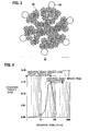
- FIG. 3 is a schematic view of catalyst powder 30, showing another example of the exhaust gas purifying catalyst according to the present invention, in which the compounds 14 as the promoter component are disposed so as to contact the second oxides 13.
- the catalyst powder 30 shown in FIG. 3 is one formed of an aggregate of plural pieces of the catalyst particle units 10 shown in FIG. 1 .
- the aggregate of the catalyst particle units 10 forms micropores of the catalyst powder.
- compounds 14 as a promoter component are provided in contact with an outer circumferential portion of the catalyst powder 30.
- the compounds 14 are provided so as to contact the second oxides 13 of the catalyst particle units 10 as constituents of the catalyst powder 30 as described above, whereby the closure of the micropores of the catalyst particle units is suppressed effectively, and at the same time, the compounds 14 as the promoter component are provided close to the noble metal particles 11, and the effect of containing the compounds 14 can be fully exerted.
- the constituents of the catalyst powder 30 are not limited to the catalyst particle units 10.
- the constituents may be the catalyst particle units 20 shown in FIG. 2 .
- the constituents may be catalyst particle units which do not directly contain the second oxides 13 therein, are composed of the noble metal particles 11, the fist oxides 12 and the second oxides 13, in which the noble metal particles 11 are supported on the first oxides 12, and the first oxides 12 supporting the noble metal particles 11 are covered with the second oxides 13.
- the constituents may be a mixture of these catalyst particle units.
- the compounds as the promoter component are disposed in contact with the second oxides of the catalyst particle units; however, the exhaust gas purifying catalyst according to the present invention is not limited to these examples.
- the catalyst particle unit that includes at least: the noble metal having the catalytic function; the fist oxides on which the noble metal is supported; and the second oxides covering the first oxides on which the noble metal is supported, oxides in which the second oxides and the compounds as the promoter component are complexed are formed.
- the second oxides are Al 2 O 3
- the promoter component is Ba
- BaAl 2 O 4 as a complex oxide can be contained.
- the closure of the catalyst micropores is suppressed, and at the same time, such compounds as the promoter component are provided close to the noble metal particle, and the effect of containing the compounds be fully exerted. Furthermore, by performing the above-described complexing, the promoter component can be micro-granulated, and hence, it becomes possible to extract a function of the promoter more.
- a measure becomes effective, which is for keeping the micropore disclosure to the minimum by blending the compounds as the promoter component together with the second oxides when the first oxides supporting the noble metal particle are covered with the second oxides
- a method becomes effective, which is for forming a catalyst layer by blending the compounds as the promoter component with catalyst powder that is composed of the noble metal particle, the first oxides and the second oxides and has an anchor coveraged structure according to the present invention.
- a method is considered, which is for forming, in different layers, the compounds as the promoter component and the powder that is composed of the noble metal particle, the first oxides and the second oxides and has the anchor coveraged structure.
- FIG. 4 is a graph showing an example of a relationship between the micropore diameter of the catalyst coated on a honeycomb carrier and the capacity of the micropores thereof, which is obtained in accordance with a BJH method. As shown in FIG.
- the capacity of the micropores with a micropore diameter of 100 nm or less is mainly derived from the catalyst powder.
- the exhaust gas cannot fully reach the catalyst active site of the noble metal and the like unless the above-described capacity is ensured to some extent.
- the inventors assiduously examined an appropriate capacity of the micropores, and found that, particularly under a condition where the capacity of the micropores with a micropore diameter of 100 nm or less is 0.20 cm 3 /g or more, the exhaust gas can fully reach the catalyst active site, and such a desired effect of adding the promoter can be exerted.
- the catalyst noble metal is Pt
- the first oxides are oxides containing at least Ce
- the second oxides are oxides containing at least A1
- the compounds as the promoter component are at least one of an oxide, a carbonate and a sulfate, which contains at least one selected from the group consisting of Na, K, Cs, Ba, Fe, Ni, Mn, Ce, La and Zr.
- compounds containing Ce are effective as the first oxides which are the anchor members.
- Al 2 O 3 becomes effective as the second oxides which are the covering members also in terms of ensuring the capacity of the micropores.
- Each of Na, K, Cs, Ba, Fe, Ni, Mn, Ce, La and Zr is a component having an effect as the promoter.
- the compounds as the promoter are an oxide or carbonate of at least one selected from the group consisting of Na, K, Cs and Ba, the compounds have a function as an adsorption material of NO x .
- the oxides of Fe, Ni and Mn function to assist the noble metal activity itself.
- the oxides of Ce, La and Zr function as oxygen storage/release materials or durability enhancement materials of the covering members.
- the compounds are not limited to those of the above-described components, and may be carbonates and sulfates.
- the catalyst noble metal is Pd
- the first oxides are oxides containing at least one of Ce and Zr
- the second oxides are the oxides containing at least Al
- the compounds as the promoter component are at least one of the oxide
- the carbonate and the sulfate which contains at least one selected from the group consisting of Na, K, Cs, Ba, Fe, Ni, Mn, Ce, La and Zr.
- compounds containing Ce and/or Zr are effective as the first oxides which are the anchor members.
- Al 2 O 3 becomes effective as the second oxides which are the covering members also in terms of ensuring the capacity of the micropores.
- Each of Na, K, Cs, Ba, Fe, Ni, Mn, Ce, La and Zr is a component having the effect as the promoter.
- the compounds as the promoter are the oxide or carbonate of at least one selected from the group consisting of Na, K, Cs and Ba, the compounds have a function as the adsorption material of NO x . When the compounds are the sulfate, this is effective to relieve HC poisoning.
- the oxides of Fe, Ni and Mn function to assist the noble metal activity itself.
- the oxides of Ce, La and Zr function as the oxygen storage/release materials or the durability enhancement materials of the covering members.
- the catalyst noble metal is Rh
- the first oxides are oxides containing at least Zr
- the second oxides are the oxides containing at least Al
- the compounds as the promoter component are at least one of the oxide, the carbonate and the sulfate, which contains at least one selected from the group consisting of Fe, Ni, Mn, Ce, La and Zr.
- Rh as such a noble metal component
- compounds containing Zr are effective as the first oxides which are the anchor members.
- Al 2 O 3 becomes effective as the second oxides which are the covering members also in terms of ensuring the capacity of the micropores.
- Each of Fe, Ni, Mn, Ce, La and Zr is a component having the effect as the promoter.
- the compounds as the promoter are an oxide of at least one selected from the group consisting of Fe, Ni and Mn, the compounds have a function to assist the noble metal activity itself.
- the oxides of Ce, La and Zr have a function as the oxygen storage/release materials or the durability enhancement materials of the covering members.
- the compounds are not limited to those of the above-described components, and may be carbonates and sulfates.
- Al 2 O 3 is suitable as the second oxides. It is preferable that Al 2 O 3 be formed of boehmite as a raw material.
- the catalyst noble metal is supported on the first compounds, and then the first compounds supporting the catalyst noble metal are covered with boehmite as the raw material of the second compounds and the compounds as the promoter component. Thereafter, a resultant is fired at 500°C or more.
- boehmite As the raw material, Al 2 O 3 suitable as the second compounds can be obtained.
- the noble metal and the first oxides as the anchor members are covered with the second oxides as the covering members, the noble metal and the first oxides are covered with a mixture of the second oxides and the compounds as the promoter.
- the micropore capacity of the second oxides can be prevented from being reduced, and the promoter component can be provided closest to the noble metal.
- the above-described resultant is fired at 500°C or more, thus also making it possible to complex the compounds as the promoter and the second oxides. In such a way, it becomes further possible to suppress the micropore closure, and to provide the promoter close to the noble metal.
- the exhaust gas purifying catalyst according to the present invention is formed by being coated on inner walls of through holes formed in a honeycomb-structure base member made of a fire-resistant inorganic material, and the exhaust gas purifying catalyst turns to a mode of a catalyst-coated layer.
- the catalyst-coated layer may be one in which the exhaust gas purifying catalyst according to the present invention is coated as a single layer, it is preferable that the exhaust gas purifying catalyst have at least two catalyst-coated layers. This is because, in the case of forming a plurality of layers different in type of the catalyst noble metal, characteristics of the catalyst noble metals are fully used, thus making it possible to enhance the catalyst performance.
- the catalyst of the suitable example, in which the above-described noble metal is Pt and/or Pd is contained on an inner layer side of the catalyst-coated layers
- the catalyst of the suitable example, in which the above-described noble metal is Rh is contained on a surface layer side of the catalyst-coated layers.
- the catalyst of the suitable example in which the above-described noble metal is Pt and/or Pd
- the catalyst of the suitable example in which the above-described noble metal is Pt and/or Pd and Rh
- the catalyst containing Rh is disposed on the surface layer side having high contact with the gas in consideration for the gas diffusibility, whereby the further effect of enhancing the catalyst activity is obtained.
- Example 1 is an example where CeO 2 as the promoter component is blended with the catalyst powder that is composed of the noble metal particles, the first oxides and the second oxides and has the anchor coverage structure, whereby the catalyst layer is formed.
- a dinitrodiamine Pt solution was supported on CeO 2 powder with a specific surface area of 70 m 2 /g so that a support concentration thereof could be 0.5 wt% in conversion to Pt. Subsequently, a resultant thus obtained was dried at 150°C day and night, and was then fired at 400°C for an hour, and Pt (0.5 wt%) /CeO 2 powder was obtained. The Pt-supported CeO 2 powder was milled, and Pt/CeO 2 powder with an average particle diameter (D50) of 200 nm was obtained.
- D50 average particle diameter
- the raw material powder of the catalyst particle units was dispersed into water, and into the water having the raw material powder dispersed thereinto, a Ce nitrate solution was impregnated so that a support concentration in conversion to CeO 2 could be 5 wt% with respect to the raw material powder of the respective catalyst particle units. In such a way, catalyst powder was obtained.
- the catalyst powder of 225 g, alumina sol of 25 g, water of 240 g and nitric acid of 10 g were put into a magnetic ball mill, followed by mixing and milling, and catalyst slurry was obtained.
- This slurry was adhered onto a cordierite monolithic carrier (0.12 L, 400 cells), and excessive slurry in the cells was removed therefrom in an airflow, followed by drying at 130°C and firing at 400°C for an hour. In such a way, a catalyst layer with a coated layer of 200 g/L was obtained.
- Example 2 is an example where, when the first oxides supporting the noble metal particles are covered with the second oxides, CeO 2 as the promoter component was blended together with the second oxides, whereby the catalyst layer is formed.
- Boehmite a Ce nitrate solution and water were mixed together, and were stirred for an hour. Subsequently, into this liquid, the Pt-supported CeO 2 powder of Example 1 was put slowly, and was further stirred for two hours. After being stirred, this liquid was dried at 80°C for three hours under a reduced pressure. Moreover, a resultant thus obtained by the drying was fired in the air at 550°C for three hours, and catalyst powder was obtained. A support concentration of Ce in conversion to CeO 2 was set at 5 wt% with respect to the catalyst powder. A ratio of the Pt-supported CeO 2 powder and the impregnated CeO 2 and Al 2 O 3 in this catalyst powder is 50: 50.
- the catalyst powder of 225 g, alumina sol of 25 g, water of 240 g and nitric acid of 10 g were put into a magnetic ball mill, followed by mixing and milling, and catalyst slurry was obtained.
- This slurry was adhered onto a cordierite monolithic carrier (0.12 L, 400 cells), and excessive slurry in the cells was removed therefrom in an airflow, followed by drying at 130°C and firing at 400°C for an hour. In such a way, a catalyst layer with a coated layer of 200 g/L was obtained.
- Example 3 is the same as Example 2 except that the catalyst powder was further fired in the air at 700°C for an hour after the step of obtaining the catalyst powder in Example 2.
- the catalyst powder was further fired at 700°C, whereby complexing of CeO 2 and Al 2 O 3 was achieved.
- Reference example 1 is an example where the CeO 2 powder as the promoter component is formed, in different layers, on outer surfaces of the catalyst powder formed of the aggregates of the catalyst particle units.
- the raw material powder of the catalyst particle units of Example 1, of which weight is 213.8 g, CeO 2 powder of 11. 2g, alumina sol of 25 g, water of 240 g and nitric acid of 10 g were put into a magnetic ball mill, followed by mixing and milling, and catalyst slurry was obtained.
- This slurry was adhered onto a cordierite monolithic carrier (0.12 L, 400 cells), and excessive slurry in the cells was removed therefrom in an airflow, followed by drying at 130°C and firing at 400°C for an hour. In such a way, a catalyst layer with a coated layer of 200 g/L was obtained.
- Comparative example 1 is an example of catalyst that does not have the anchor coverage structure.
- a Ce nitrate solution was supported on Al 2 O 3 with a specific surface area of 190 m 2 /g so that a support concentration of Ce could be 55 wt% in conversion to CeO 2 . Subsequently, a resultant thus obtained was dried at 150°C day and night, and was then fired at 400°C for an hour. On the powder thus obtained, a dinitrodiamine Pt solution was supported so that a support concentration thereof could be 0.5 wt%. After Pt was supported, the powder was dried at 150°C day and night, followed by firing at 400°C for an hour.
- the powder after being fired of which weight is 225 g, alumina sol of 25 g, water of 240 g and nitric acid of 10 g were put into a magnetic ball mill, followed by mixing and milling, and catalyst slurry was obtained.
- This slurry was adhered onto a cordierite monolithic carrier (0.12 L, 400 cells), and excessive slurry in the cells was removed therefrom in an airflow, followed by drying at 130°C and firing at 400°C for an hour. In such a way, a catalyst layer with a coated layer of 200 g/L was obtained.
- HC conversion rate % catalyst inlet HC concentration - calalyst outlet HC concentration / catalyst inlet HC concentration ⁇ 100
- CO conversion rate % catalyst inlet CO concentration - calalyst outlet CO concentration / catalyst inlet CO concentration ⁇ 100
- NO x conversion rate % catalyst inlet NO x concentration - calalyst outlet NO x concentration / catalyst inlet CO x concentration ⁇ 100
- Table 1 shows results of obtaining capacities of micropores with a diameter of 100 nm or less and the 50%-conversion-rate temperatures after the durability test for the catalyst layers of Examples 1 to 3, Reference example 1 and Comparative example 1, which are described above.
- Table 1 Noble metal A Oxide B Oxide C Compound D Capacity of micropores with diameter of 100 nm or less (cm 3 /g) 50%-conversion-rate temperature after durability (°C) HC CO NOx
- Example 1 Pt CeO 2 Al 2 O 3 CeO 2 0.35 361 354 356
- the catalysts of Examples 1 to 3 and Reference example 1, which were according to the present invention were catalyst in which the 50%-conversion-rate temperatures were low and the low-temperature activity was good.
- the catalysts of Example 2 and Example 3 had lower 50%-conversion-rate temperatures than Example 1 and Reference example 1, and were provided with excellent catalyst characteristics.
- Example 4 is an example where a catalyst structure is similar to that of Example 2, and a micropore capacity is different from that of Example 2.
- Example 4 is the same as Example 2 except that, in the drying step in the process of obtaining the catalyst powder, the mixed solution was sprayed from a nozzle onto a hot plate at 400°C, followed by drying.
- Example 5 is an example where a catalyst structure is similar to that of Example 2, and a micropore capacity is different from that of Example 2.
- Example 5 is the same as Example 2 except that, in the drying step in the process of obtaining the catalyst powder, the temperature at the drying under the reduced pressure was set at 60 °C, and the drying time was set at 24 hours.
- Table 2 shows results of obtaining the capacities of the micropores with a diameter of 100 nm or less and the 50%-conversion-rate temperatures after the durability test for the catalyst layers of Example 2 and Example 3.
- Table 2 Noble metal A Oxide B Oxide C Compound D Capacity of micropores with diameter of 100 nm or less (cm 3 /g) 50%-conversion-rate temperature after durability (°C) HC CO NOx
- Example 2 Pt CeO 2 Al 2 O 3 CeO 2 0.39 342 338 340
- Example 4 Pt CeO 2 Al 2 O 3 CeO 2 0.51 332 325 323
- the catalyst of Example 4 was catalyst in which the capacity of the micropores with a diameter of 100 nm or less was larger, the 50%-conversion-rate temperature after the durability test was lower, and the low-temperature activity was better than those of Example 2. Moreover, as a result of comparing Example 5 with Examples 2 and 4, it is understood that, by the fact that the capacity of the micropores with a diameter of 100 nm or less is 0.2 cm 3 /g, the catalyst is obtained, in which the 50%-conversion-rate temperature after the durability test is low, and the low-temperature activity is good.
- Example 6 is an example where the compounds as the promoter component are complex oxides of Ce and Zr.
- Boehmite a Ce nitrate solution, Zr nitrate and water were mixed together, and were stirred for an hour.
- the Pt-supported CeO 2 powder of Example 1 was put slowly, and was further stirred for two hours. After being stirred, this liquid was dried at 80°C for three hours under a reduced pressure. Moreover, a resultant thus obtained by the drying was fired in the air at 550°C for three hours, and raw material powder of the catalyst particle units was obtained.
- a support concentration of Ce in conversion to CeO 2 was set at 5 wt%
- a support concentration of Zr in conversion to ZrO 2 was set at 5 wt%.
- a ratio of the Pt-supported CeO 2 powder and the impregnated CeO 2 and Al 2 O 3 in the raw material powder of the catalyst particle units is 50: 50.
- Such catalyst particle unit raw material powder of 225 g, alumina sol of 25 g, water of 240 g and nitric acid of 10 g were put into a magnetic ball mill, followed by mixing and milling, and catalyst slurry was obtained.
- This slurry was adhered onto a cordierite monolithic carrier (0.12 L, 400 cells), and excessive slurry in the cells was removed therefrom in an airflow, followed by drying at 130°C and firing at 400°C for an hour. In such a way, a catalyst layer with a coated layer of 200 g/L was obtained.
- Example 7 is an example where the first oxides are complex oxides of Ce and Zr, and the compounds as the promoter component are complex oxides of Ce and Zr.
- a dinitrodiamine Pt solution was supported on the complex oxides (specific surface area: 65 m 2 /g) of Ce and Zr so that a support concentration thereof could be 0.5 wt% in conversion to Pt.
- a resultant thus obtained was dried at 150°C day and night, and was then fired at 400°C for an hour, and Pt (0.5 wt%)/CeZrO x powder was obtained. This powder was milled, and Pt/CeZrO x powder with an average particle diameter (D50) of 150 nm was obtained.
- Such catalyst particle unit raw material powder of 225 g, alumina sol of 25 g, water of 240 g and nitric acid of 10 g were put into a magnetic ball mill, followed by mixing and milling, and catalyst slurry was obtained.
- This slurry was adhered onto a cordierite monolithic carrier (0.12 L, 400 cells), and excessive slurry in the cells was removed therefrom in an airflow, followed by drying at 130°C and firing at 400°C for an hour. In such a way, a catalyst layer with a coated layer of 200 g/L was obtained.
- Example 8 is an example where the compounds as the promoter component are La 2 O 3 .
- Catalyst of Example 8 was produced under the same conditions as those of the above-described Example 7 except that the raw materials to be mixed in the water together with the boehmite were changed to La nitrate from the Ce nitrate and the Zr nitrate in Example 7 (support concentration of La is 5 wt% in conversion to La 2 O 3 ) .
- support concentration of La is 5 wt% in conversion to La 2 O 3
- a ratio of the Pt/CeZrO x powder and La 2 O 3 + Al 2 O 3 is 50: 50.
- Example 9 is an example where the compounds as the promoter component are complex oxides of Ce and Zr, and La 2 O 3 .
- Catalyst of Example 9 was produced under the same conditions as those of the above-described Example 7 except that the raw materials to be mixed in the water together with the boehmite were prepared by adding La nitrate to the Ce nitrate and the Zr nitrate in Example 7 (support concentration of Ce is 5 wt% in conversion to CeO 2 , support concentration of Zr is 3 wt% in conversion to ZrO 2 , and support concentration of La is 3 wt% in conversion to La 2 O 3 ) .
- a ratio of the Pt/CeZrO x powder and CeO 2 + ZrO 2 + La 2 O 3 + Al 2 O 3 is 50: 50.
- Example 10 is an example where the compounds as the promoter component are Na 2 O.
- Catalyst of Example 10 was produced under the same conditions as those of the above-described Example 7 except that the raw materials to be mixed in the water together with the boehmite were changed to Na acetate from the Ce nitrate and the Zr nitrate in Example 7 (support concentration of Na is 3 wt% in conversion to Na 2 O).
- support concentration of Na is 3 wt% in conversion to Na 2 O.
- a ratio of the Pt/CeZrO x powder and Na 2 O + Al 2 O 3 is 50: 50.
- Example 11 is an example where the compounds as the promoter component are K 2 O.
- Catalyst of Example 11 was produced under the same conditions as those of the above-described Example 7 except that the raw materials to be mixed in the water together with the boehmite were changed to K acetate from the Ce nitrate and the Zr nitrate in Example 7 (support concentration of K is 3 wt% in conversion to K 2 O).
- support concentration of K is 3 wt% in conversion to K 2 O.
- a ratio of the Pt/CeZrO x powder and K 2 O + Al 2 O 3 is 50: 50.
- Example 12 is an example where the compounds as the promoter component are Cs 2 O.
- Catalyst of Example 12 was produced under the same conditions as those of the above-described Example 7 except that the raw materials to be mixed in the water together with the boehmite were changed to Cs acetate from the Ce nitrate and the Zr nitrate in Example 7 (support concentration of Cs is 3 wt% in conversion to Cs 2 O).
- support concentration of Cs is 3 wt% in conversion to Cs 2 O.
- a ratio of the Pt/CeZrO x powder and Cs 2 O + Al 2 O 3 is 50: 50.
- Example 13 is an example where the compounds as the promoter component are BaO.
- Catalyst of Example 13 was produced under the same conditions as those of the above-described Example 7 except that the raw materials to be mixed in the water together with the boehmite were changed to Ba acetate from the Ce nitrate and the Zr nitrate in Example 7 (support concentration of Ba is 3 wt% in conversion to BaO).
- support concentration of Ba is 3 wt% in conversion to BaO.
- a ratio of the Pt/CeZrO x powder and BaO + Al 2 O 3 is 50: 50.
- Example 14 is an example where the compounds as the promoter component are Fe 2 O 3 .
- Catalyst of Example 14 was produced under the same conditions as those of the above-described Example 7 except that the raw materials to be mixed in the water together with the boehmite were changed to Fe nitrate from the Ce nitrate and the Zr nitrate in Example 7 (support concentration of Fe is 5 wt% in conversion to Fe 2 O 3 ).
- support concentration of Fe is 5 wt% in conversion to Fe 2 O 3 .
- a ratio of the Pt/CeZrO x powder and Fe 2 O 3 + Al 2 O 3 is 50: 50.
- Example 15 is an example where the compounds as the promoter component are Ni 2 O 3 .
- Catalyst of Example 15 was produced under the same conditions as those of the above-described Example 7 except that the raw materials to be mixed in the water together with the boehmite were changed to Ni nitrate from the Ce nitrate and the Zr nitrate in Example 7 (support concentration of Ni is 5 wt% in conversion to Ni 2 O 3 ).
- support concentration of Ni is 5 wt% in conversion to Ni 2 O 3 .
- a ratio of the Pt/CeZrO x powder and Ni 2 O 3 + Al 2 O 3 is 50: 50.
- Example 16 is an example where the compounds as the promoter component are Mn 2 O 3 .
- Catalyst of Example 16 was produced under the same conditions as those of the above-described Example 7 except that the raw materials to be mixed in the water together with the boehmite were changed to Mn nitrate from the Ce nitrate and the Zr nitrate in Example 7 (support concentration of Mn is 5 wt% in conversion to Mn 2 O 3 ).
- support concentration of Mn is 5 wt% in conversion to Mn 2 O 3 ).
- a ratio of the Pt/CeZrO x powder and Mn 2 O 3 + Al 2 O 3 is 50: 50.
- Example 17 is an example where the noble metal is Pd, and the compounds as the promoter component are BaSO 4 .
- a Pd nitrate solution was supported on CeO 2 powder with a specific surface area of 70 m 2 /g so that a support concentration thereof could be 1.0 wt% in conversion to Pd.
- a resultant thus obtained was dried at 150°C day and night, and was then fired at 400°C for an hour, and Pd (1.0 wt%) /CeO 2 powder was obtained.
- This powder was milled, and Pd/CeO 2 powder with an average particle diameter (D50) of 170 nm was obtained.
- Such catalyst particle unit raw material powder of 225 g, alumina sol of 25 g, water of 240 g and nitric acid of 10 g were put into a magnetic ball mill, followed by mixing and milling, and catalyst slurry was obtained.
- This slurry was adhered onto a cordierite monolithic carrier (0.12 L, 400 cells), and excessive slurry in the cells was removed therefrom in an airflow, followed by drying at 130°C and firing at 400°C for an hour. In such a way, a catalyst layer with a coated layer of 200 g/L was obtained.
- Example 18 is an example where the compounds as the promoter component are Fe 2 O 3 .
- Catalyst of Example 18 was produced under the same conditions as those of the above-described Example 17 except that the raw materials to be mixed in the water together with the boehmite were changed to Fe nitrate from the Ba acetate and the nitric acid in Example 17 (support concentration of Fe is 5 wt% in conversion to Fe 2 O 3 ).
- support concentration of Fe is 5 wt% in conversion to Fe 2 O 3 .
- a ratio of the Pd/CeO 2 powder and Fe 2 O 3 + Al 2 O 3 is 50: 50.
- Example 19 is an example where the compounds as the promoter component are Ni 2 O 3 .
- Catalyst of Example 19 was produced under the same conditions as those of the above-described Example 17 except that the raw materials to be mixed in the water together with the boehmite were changed to Ni nitrate from the Ba acetate and the nitric acid in Example 17 (support concentration of Ni is 5 wt% in conversion to Ni 2 O 3 ) .
- support concentration of Ni is 5 wt% in conversion to Ni 2 O 3
- a ratio of the Pd/CeO 2 powder and Ni 2 O 3 + Al 2 O 3 is 50: 50.
- Example 20 is an example where the compounds as the promoter component are complex oxides of Ce and Zr.
- Catalyst of Example 20 was produced under the same conditions as those of the above-described Example 17 except that the raw materials to be mixed in the water together with the boehmite were changed to Ce nitrate and Zr nitrate from the Ba acetate and the nitric acid in Example 17 (support concentration of Ce is 5 wt% in conversion to CeO 2 , and support concentration of Zr is 5 wt% in conversion to ZrO 2 ).
- a ratio of the Pd/CeO 2 powder and CeO 2 + ZrO 2 + Al 2 O 3 is 50: 50.
- Example 21 is an example where the first oxides are ZrO 2 .
- Catalyst of Example 21 was produced under the same conditions as those of the above-described example 20 except that the CeO 2 powder with a specific surface area of 70 m 2 /g, which is a raw material of the Pd/CeO 2 powder in Example 20, was changed to ZrO 2 powder with a specific surface area of 50 m 2 /g.
- Example 22 is an example where the noble metal is Rh, and both of the first oxides and the compounds as the promoter component are ZrO 2 .
- Rh nitrate solution was supported on ZrO 2 powder with a specific surface area of 50 m 2 /g so that a support concentration thereof could be 0.3 wt% in conversion to Rh.
- a resultant thus obtained was dried at 150°C day and night, and was then fired at 400°C for an hour, and Rh (0.3 wt%)/ZrO 2 powder was obtained.
- This powder was milled, and Rh/ZrO 2 powder with an average particle diameter (D50) of 160 nm was obtained.
- Such catalyst particle unit raw material powder of 225 g, alumina sol of 25 g, water of 240 g and nitric acid of 10 g were put into a magnetic ball mill, followed by mixing and milling, and catalyst slurry was obtained.
- This slurry was adhered onto a cordierite monolithic carrier (0.12 L, 400 cells), and excessive slurry in the cells was removed therefrom in an airflow, followed by drying at 130°C and firing at 400°C for an hour. In such a way, a catalyst layer with a coated layer of 200 g/L was obtained.
- Example 23 is an example where the first oxides are complex oxides of La and Zr.
- Catalyst of Example 23 was produced under the same conditions as those of the above-described example 22 except that the ZrO 2 powder with a specific surface area of 50 m 2 /g, which is a raw material of the Rh/ZrO 2 powder in Example 22, was changed to LaZrO x powder with a specific surface area of 55 m 2 /g.
- Example 24 is an example where the compounds as the promoter component are complex oxides of Ce and Zr.
- Catalyst of Example 24 was produced under the same conditions as those of the above-described Example 23 except that the raw materials to be mixed in the water together with the boehmite were changed to Ce nitrate and Zr nitrate from the Zr nitrate in Example 23 (support concentration of Ce is 5 wt% in conversion to CeO 2 , and support concentration of Zr is 5 wt% in conversion to ZrO 2 ).
- a ratio of the Rh/ZrO 2 powder and CeO 2 + ZrO 2 + Al 2 O 3 is 50: 50.
- Example 25 is an example where the compounds as the promoter component are La 2 O 3 .
- Example 24 is an example where the compounds as the promoter component are complex oxides of Ce and Zr.
- Catalyst of Example 25 was produced under the same conditions as those of the above-described Example 23 except that the raw materials to be mixed in the water together with the boehmite were changed to La nitrate from the Zr nitrate in Example 23 (support concentration of La is 5 wt% in conversion to La 2 O 3 , and support concentration of Zr is 5 wt% in conversion to ZrO 2 ).
- a ratio of the Rh/ZrO 2 powder and La 2 O 3 + Al 2 O 3 is 50: 50.
- Table 3 shows results of obtaining the capacities of the micropores with a diameter of 100 nm or less and the 50%-conversion-rate temperatures after the durability test for the catalyst layers of the above-described Example 6 to Example 25.
- Table 3 Noble metal A Oxide B Oxide C Compound D Capacity of micropores with diameter of 100 nm or less (cm 3 /g) 50%-conversion-rate temperature after durability (°C) HC CO NOx
- Example 6 Pt CeO 2 Al 2 O 3 CeZrOx 0.37 340 337 336
- Example 7 Pt CeZrOx Al 2 O 3 CeZrOx 0.37 339 337 337
- Example 8 Pt CeZrOx Al 2 O 3 La 2 O 3 0.38 341 337 331
- Example 9 Pt CeZrOx Al 2 O 3 CeZrOx, La 2 O 3 0.35 340 336 336
- Example 10 Pt CeZrOx Al 2 O 3 Na 2 O 0.36 343 339 328
- each of the catalysts of Example 6 to example 25 according to the present invention was catalyst in which the 50%-conversion-rate temperature after the durability test was low and the low-temperature activity was good.
- Example 26 is an example where the firing temperature condition at the time of the production is differentiated.
- Catalyst of Example 26 was produced under the same conditions as those of Example 2 except that the firing temperature was set at 400°c in the step of obtaining the catalyst powder in Example 2.
- Table 4 shows results of obtaining the capacity of the micropores with a diameter of 100 nm or less and the 50%-conversion-rate temperature after the durability test for the catalyst layers of Example 26 in combination with the results in Example 2.
- Table 4 Noble metal A Oxide B Oxide C Compound D Aspect ratio of boehmite Firing temperature (° C) 50%-conversion-rate temperature after durability (° C) HC CO NOx
- Example 2 Pt CeO 2 Al 2 O 3 CeO 2 1.1 550 342 338 340
- Example 26 Pt CeO 2 Al 2 O 3 CeO 2 1.1 400 364 355 354
- the catalyst of Example 26 according to the present invention was catalyst in which the 50%-conversion-rate temperature after the durability test was low and the low-temperature activity was good in a similar way to the catalyst of Example 2.
- the catalyst in Example 2 was catalyst in which the 50%-conversion-rate temperature after the durability test is lower, and the low-temperature activity is better.
- Example 27 to Example 33 are examples, in each of which the catalyst-coated layer formed by being coated on the honeycomb-structure base members made of the fire-resistant inorganic material includes totally two catalyst-coated layers on the inner layer side and the surface layer side.
- the respective catalysts were disposed on cordierite monolithic carriers (1.2 L, 400 cells).
- the firing was performed every time when each of the layers was coated, and such firing for the two layers was performed in the air at 400°C for an hour.
- the coated layers was set at 150 g/L on the inner layer side, and at 70 g/L on the surface layer side.
- Example 27 Catalyst of Example 7 Catalyst of Example 23 298 287 285
- Example 28 Catalyst of Example 20 Catalyst of Example 23 287 281 280
- Example 29 Catalysts of Examples 7 and 20 Catalyst of Example 23 285 280 278
- Example 30 Catalyst of Example 7 Catalysts of Examples 7 and 23 295 285 284
- Example 31 Catalysts of Examples 7 and 20 Catalysts of Examples 7 and 23 283 277 276
- Example 32 Catalysts of Examples 7 and 20 Catalysts of Examples 7, 20 and 23 282 275 275
- Example 33 Catalyst of Examples 23 Catalyst of Example 7 310 305 304
- Table 5 shows, in a lump, results of obtaining the capacities of the micropores with a diameter of 100 nm or less and the 50%-conversion-rate temperatures after the durability test for the catalyst layers of Example 27 to Example 33, which are described above.
- each of the exhaust gas purifying catalysts according to the present invention can be made to include the two catalyst-coated layers, and even in this case, was the catalyst in which the 50%-conversion-rate temperature after the durability test was low and the low-temperature activity was good.
- Example 33 is an example where the catalyst containing Rh is disposed on the inner layer side and is not disposed on the outer layer side.
- the catalysts of Example 27 to Example 32 in each of which the catalyst containing Rh is disposed on the outer layer side, were catalysts, in each of which the 50%-conversion-rate temperature after the durability test is lower, and the low-temperature activity is better.
Abstract
Description
- The present invention relates to an exhaust gas purifying catalyst suitable for application to processing for purifying exhaust gas discharged from an internal combustion engine, and relates to a producing method thereof.
- In recent years, in order to remove toxic substances such as a hydrocarbon compound (HC), a carbon monoxide (CO) and a nitrogen oxide (NOx), which are contained in exhaust gas discharged from an internal combustion engine, an exhaust gas purifying catalyst has been widely used, in which noble metal particles of platinum (Pt) and the like are supported on a metal oxide support of alumina (Al2O3) or the like. In the conventional exhaust gas purifying catalyst, in order to enhance durability of the noble metal particles against variations of the ambient atmosphere, a large amount of the noble metal particles are used. However, it is not desirable to use the large amount of noble metal particles from a viewpoint of protecting earth resources.
- From such a background, recently, attempts have been made, which are to enhance the durability of the noble metal particles in such a manner that transition metal such as cerium (Ce) and manganese (Mn) or a transition metal compound, which functions as an oxygen storage component (OSC) material, is disposed in the vicinities of the noble metal particles by an impregnation method, and the variations of the ambient atmosphere of the noble metal particles are suppressed by the transition metal or the transition metal compound (refer to
Japanese Patent Laid-Open Publications No. H8-131830 (published in 1996 No. 2005-000829 No. 2005-000830 No. 2003-117393 - In the case of suppressing the variations of the ambient atmosphere of the noble metal particles by the compound of the transition metal, it is necessary that both of the noble metal particles and compound particles of the transition metal be microparticles, and that both thereof contact each other. However, in the case of using the impregnation method, both of the noble metal particles and the compound particles of the transition metal do not become the microparticles even if both thereof can be contacted with each other. Alternatively, both of the above can not be contacted with each other or an amount thereof capable of being contacted with each other is small even if both become the microparticles, and accordingly, it is difficult to dispose the compound particles of the transition metal in the vicinities of the noble metal particles as designed. Moreover, in the case of achieving the durability of the noble metal particles, it is desirable to set an average particle diameter of the noble metal particles at 2 [nm] or more, and in the case of achieving the activity of the noble metal particles, it is desirable to set an average particle diameter at 5 [nm] or less. However, in the case of using the impregnation method, the average particle diameter of the noble metal particles becomes 1.5 [nm] or less, and accordingly, it is difficult to expect the durability enhancement and activity enhancement of the noble metal particles.
- Moreover, the compound of the transition metal is likely to be solid-solved in alumina widely used as the metal oxide support, and accordingly, only if the compound of the transition metal is merely disposed in the vicinities of the noble metal particles, then it is difficult to obtain an effect of enhancing the activity of the noble metal particles. Note that a method of supporting the compound of the transition metal on a support that is not solid-solved in the compound of the transition metal is considered in order to solve such a problem; however, in the case of using this method, the compound of the transition metal moves in a high-temperature atmosphere, and the respective pieces of the compound of the transition metal are contacted with one another, whereby the compound of the transition metal coagulates. Moreover, in order to prevent such coagulation, there is also considered a method of producing compound particles of the transition metal with a large surface area by using a reversed micelle method; however, since an organic solvent is used in this method, production cost and a load on the environment are large.
- In order to solve the above-described problems, an exhaust gas purifying catalyst according to the present invention is summarized to include: a catalyst particle unit having at least noble metal with a catalytic function, first oxides on which the noble metal is supported, and second oxides covering the first oxides on which the catalyst noble metal is supported, wherein at least one type of compounds selected from the group consisting of a transition element, an alkali earth metal element, an alkali metal element, and a rare earth element, which is a promoter component, are contained in catalyst powder formed of an aggregate of plural pieces of the catalyst particle units.
- Moreover, a method of producing an exhaust gas purifying catalyst according to the present invention is a method of producing the above-described exhaust gas purifying catalyst summarized to include: supporting the catalyst noble metal on the first compounds; covering the first compounds supporting the catalyst noble metal with a mixture of boehmite as a raw material of the second compounds and the compounds as the promoter component; and firing a resultant of THE mixture and the catalyst noble metal covered therewith at 500°C or more.
- The above and further objects, features and advantages of the invention will more fully appear in the detailed description of embodiments of the invention, when the same is read in conjunction with the drawings, in which:
-
FIG. 1 is a schematic view of a catalyst particle unit in an exhaust gas purifying catalyst serving as an embodiment of the present invention; -
FIG. 2 is a schematic view of a catalyst particle unit in an exhaust gas purifying catalyst serving as another embodiment of the present invention; -
FIG. 3 is a schematic view of catalyst powder in an exhaust gas purifying catalyst serving as another embodiment of the present invention; and -
FIG. 4 is a graph showing an example of a relationship between a micropore diameter and an overall capacity of micropores. - A description will be made below of embodiments of an exhaust gas purifying catalyst of the present invention while using the drawings.
-
FIG. 1 is a schematic view of a catalyst particle unit in an exhaust gas purifying catalyst serving as an embodiment of the present invention. Acatalyst particle unit 10 of the exhaust gas purifying catalyst shown inFIG. 1 includes: anoble metal particle 11 having a catalytic function;first oxides 12 which support thenoble metal particle 11, and suppress movement of thenoble metal particle 11;second oxides 13 which cover thenoble metal particle 11 and thefirst oxides 12, and suppress coagulation of thefirst oxides 12, the coagulation following mutual contact of thefirst oxides 12, as well as suppress the movement of thenoble metal particle 11; andcompounds 14 as a promoter component disposed in the vicinities of the second oxides. Thecompounds 14 contain at least one type of compounds selected from the group consisting of a transition element, an alkali earth metal element, an alkali metal element, and a rare earth element. Moreover, thecatalyst particle unit 10 is formed to have a structure, in which a plurality of aggregates of thefirst oxides 12 supporting thenoble metal particles 11 are covered with thesecond oxides 13, whereby the plurality of aggregates of thefirst oxides 12 supporting thenoble metal particles 11 are separated from one another by thesecond oxides 13. - As a result of repeating an energetic research, the inventors of the present invention found that the noble metal particles are chemically bonded to the oxides, thus making it possible to chemically suppress the movement of the noble metal particles, and that the noble metal particles are covered with the other oxides, thus making it possible to physically suppress the movement of the noble metal particles. Moreover, the inventors found that both of the noble metal particles and the oxides are covered with the other oxides, thus making it possible to suppress the coagulation of the oxides as well as to suppress the movement of the noble metal particles.
- In the
catalyst particle unit 10 of the exhaust gas purifying catalyst, which is shown inFIG. 1 and configured based on the findings described above, thefirst oxides 12 contact and support thenoble metal particle 11, whereby thefirst oxides 12 function as anchor members of the chemical bonding, and suppress the movement of thenoble metal 11. Moreover, such a mode in which thenoble metal particle 11 and thefirst oxides 12 are covered with thesecond oxides 13 is adopted, whereby the movement of thenoble metal particle 11 is physically suppressed. Furthermore, thecatalyst particle unit 10 includes thenoble metal particle 11 and thefirst oxides 12 in a section separated from the others by thesecond oxides 13, thereby suppressing movement of thefirst oxides 12 beyond the section separated by thesecond oxides 13, and suppressing contact and coagulation thereof with the others. From these facts, without increasing the production cost and the load on the environment, the exhaust gas purifying catalyst having the structure of thecatalyst particle unit 10 shown inFIG. 1 can prevent a decrease of catalyst activity, which may be caused by the coagulation of thenoble metal particles 11, and further, can maintain the effect of enhancing the activity of thenoble metal particles 11, which is brought by thefirst oxides 12. Hence, an exhaust gas purifying catalyst, which has high heat resistance and keeps excellent durability for a long period, can be obtained. - Moreover, in the
catalyst particle unit 10 of the exhaust gas purifying catalyst of this embodiment, which is shown inFIG. 1 , thecompounds 14 as the promoter component are disposed in contact with thesecond oxides 13. It is effective that the promoter component is contained in the catalyst since performance of the catalyst can be enhanced. However, when thecatalyst particle unit 10 having the above-described structure contains the promoter component, there has been an apprehension that an effect of containing the promoter component cannot be fully exerted depending on a mode of the structure in which the promoter component is contained. In detail, the structure of thecatalyst particle unit 10 is extremely effective in enhancing heat resistance of thenoble metal particle 11, and thenoble metal particle 11 at a catalyst active site is covered with thesecond oxides 13, and thenoble metal particle 11 contacts gas through micropores of thesecond oxides 13. Here, in a structure in which the promoter is added by impregnation supporting in a similar way to the conventional catalyst, there is an apprehension that the micropores of the catalyst may be closed by the promoter, gas diffusion may suffer a failure, and the gas may fail to reach the active site. - Therefore, in order to fully exert the effect of the promoter, it is necessary to dispose the promoter in a mode in which micropore closure is prevented as much as possible from occurring. Moreover, if the promoter component is disposed too apart from the noble metal particle, the effect of containing the promoter component becomes poor. In consideration for such factors, in the exhaust gas purifying catalyst of this embodiment, which is shown in
FIG. 1 , thecompounds 14 as the promoter component are disposed so as not to contact thefirst oxides 12 but to contact thesecond oxides 13, and more specifically, disposed so as to contact thesecond oxides 13 at positions among thesecond oxides 13 adjacent to one another. Thecompounds 14 are provided so as to contact thesecond oxides 13 as described above, whereby the closure of the micropores in the catalyst particle unit, which are formed of the adjacentsecond oxides 13, are kept to the minimum, and the effect of containingcompounds 14 can be exerted to the maximum. -
FIG. 2 is a schematic view of acatalyst particle unit 20, showing another example of the exhaust gas purifying catalyst according to the present invention, in which thecompounds 14 as the promoter component are disposed so as to contact thesecond oxides 13. Note that, inFIG. 2 , the same reference numerals are assigned to the same constituents as those inFIG. 1 . Thecatalyst particle unit 20 shown inFIG. 2 includes: thenoble metal particle 11 having the catalytic function; thefirst oxides 12 which support thenoble metal particle 11, and suppress the movement of thenoble metal particle 11; thesecond oxides 13 which cover thenoble metal particle 11 and thefirst oxides 12, and suppress the coagulation of thefirst oxides 12, the coagulation following the mutual contact of thefirst oxides 12, as well as suppress the movement of thenoble metal particle 11; and thecompounds 14 as the promoter component disposed in the vicinities of the second oxides. In the above-described point, thecatalyst particle unit 20 is the same as thecatalyst particle unit 10. Then, in thecatalyst particle unit 20 shown inFIG. 2 , thecompounds 14 as the promoter component are disposed so as to contact thesecond oxides 13, and more specifically, disposed so as to contact outer circumferential surfaces of thesecond oxides 13. Thecompounds 14 are provided so as to contact thesecond oxides 13 as described above, whereby the closure of the micropores of the catalyst particle unit is suppressed effectively, and at the same time, thecompounds 14 as the promoter component are provided close to thenoble metal particle 11, and the effect of containing thecompounds 14 can be fully exerted. -
FIG. 3 is a schematic view ofcatalyst powder 30, showing another example of the exhaust gas purifying catalyst according to the present invention, in which thecompounds 14 as the promoter component are disposed so as to contact thesecond oxides 13. Thecatalyst powder 30 shown inFIG. 3 is one formed of an aggregate of plural pieces of thecatalyst particle units 10 shown inFIG. 1 . The aggregate of thecatalyst particle units 10 forms micropores of the catalyst powder. Then,compounds 14 as a promoter component are provided in contact with an outer circumferential portion of thecatalyst powder 30. Thecompounds 14 are provided so as to contact thesecond oxides 13 of thecatalyst particle units 10 as constituents of thecatalyst powder 30 as described above, whereby the closure of the micropores of the catalyst particle units is suppressed effectively, and at the same time, thecompounds 14 as the promoter component are provided close to thenoble metal particles 11, and the effect of containing thecompounds 14 can be fully exerted. - Note that, in the example shown in
FIG. 3 , an example is shown, where thecatalyst powder 30 is the aggregate of thecatalyst particle units 10; however, the constituents of thecatalyst powder 30 are not limited to thecatalyst particle units 10. For example, the constituents may be thecatalyst particle units 20 shown inFIG. 2 . Alternatively, the constituents may be catalyst particle units which do not directly contain thesecond oxides 13 therein, are composed of thenoble metal particles 11, thefist oxides 12 and thesecond oxides 13,
in which thenoble metal particles 11 are supported on thefirst oxides 12, and thefirst oxides 12 supporting thenoble metal particles 11 are covered with thesecond oxides 13. Alternatively, the constituents may be a mixture of these catalyst particle units. - In the examples shown in
FIG. 1 to FIG. 3 , examples are explained, where the compounds as the promoter component are disposed in contact with the second oxides of the catalyst particle units; however, the exhaust gas purifying catalyst according to the present invention is not limited to these examples. As another example, there is an example where, in the catalyst particle unit that includes at least: the noble metal having the catalytic function; the fist oxides on which the noble metal is supported; and the second oxides covering the first oxides on which the noble metal is supported, oxides in which the second oxides and the compounds as the promoter component are complexed are formed. For example, when the second oxides are Al2O3, and the promoter component is Ba, BaAl2O4 as a complex oxide can be contained. Even in this example where the above-described complex oxide is contained in the catalyst particle unit, in a similar way to the examples explained by usingFIG. 1 to FIG. 3 , the closure of the catalyst micropores is suppressed, and at the same time, such compounds as the promoter component are provided close to the noble metal particle, and the effect of containing the compounds be fully exerted. Furthermore, by performing the above-described complexing, the promoter component can be micro-granulated, and hence, it becomes possible to extract a function of the promoter more. - As means for obtaining the exhaust gas purifying catalyst according to the present invention, a measure becomes effective, which is for keeping the micropore disclosure to the minimum by blending the compounds as the promoter component together with the second oxides when the first oxides supporting the noble metal particle are covered with the second oxides, and a method becomes effective, which is for forming a catalyst layer by blending the compounds as the promoter component with catalyst powder that is composed of the noble metal particle, the first oxides and the second oxides and has an anchor coveraged structure according to the present invention. As another method, a method is considered, which is for forming, in different layers, the compounds as the promoter component and the powder that is composed of the noble metal particle, the first oxides and the second oxides and has the anchor coveraged structure.
- In the exhaust gas purifying catalyst according to the present invention, it is preferable that a capacity of the micropores with a micropore diameter of 100 nm or less be 0.20 cm3/g or more. In the catalyst of the present invention, the noble metal and the first oxides as the anchor members are covered with the second compounds which are covering members such as alumina. Therefore, it becomes more important to improve gas diffusibility even than catalyst formed by the conventional impregnation method.
FIG. 4 is a graph showing an example of a relationship between the micropore diameter of the catalyst coated on a honeycomb carrier and the capacity of the micropores thereof, which is obtained in accordance with a BJH method. As shown inFIG. 4 , the capacity of the micropores with a micropore diameter of 100 nm or less is mainly derived from the catalyst powder. The exhaust gas cannot fully reach the catalyst active site of the noble metal and the like unless the above-described capacity is ensured to some extent. The inventors assiduously examined an appropriate capacity of the micropores, and found that, particularly under a condition where the capacity of the micropores with a micropore diameter of 100 nm or less is 0.20 cm3/g or more, the exhaust gas can fully reach the catalyst active site, and such a desired effect of adding the promoter can be exerted. - As a suitable example of a combination of the noble metal, the first oxides, the second oxides and the compounds as the promoter component in the exhaust gas purifying catalyst according to the present invention, one is mentioned, in which the catalyst noble metal is Pt, the first oxides are oxides containing at least Ce, the second oxides are oxides containing at least A1, the compounds as the promoter component are at least one of an oxide, a carbonate and a sulfate, which contains at least one selected from the group consisting of Na, K, Cs, Ba, Fe, Ni, Mn, Ce, La and Zr. In the case of using Pt as such a noble metal component, compounds containing Ce are effective as the first oxides which are the anchor members. Moreover, Al2O3 becomes effective as the second oxides which are the covering members also in terms of ensuring the capacity of the micropores. Each of Na, K, Cs, Ba, Fe, Ni, Mn, Ce, La and Zr is a component having an effect as the promoter. When the compounds as the promoter are an oxide or carbonate of at least one selected from the group consisting of Na, K, Cs and Ba, the compounds have a function as an adsorption material of NOx. Moreover, the oxides of Fe, Ni and Mn function to assist the noble metal activity itself. Furthermore, the oxides of Ce, La and Zr function as oxygen storage/release materials or durability enhancement materials of the covering members. The compounds are not limited to those of the above-described components, and may be carbonates and sulfates.
- As another suitable example of the combination of the noble metal, the first oxides, the second oxides and the compounds as the promoter component in the exhaust gas purifying catalyst according to the present invention, one is mentioned, in which the catalyst noble metal is Pd, the first oxides are oxides containing at least one of Ce and Zr, the second oxides are the oxides containing at least Al, the compounds as the promoter component are at least one of the oxide, the carbonate and the sulfate, which contains at least one selected from the group consisting of Na, K, Cs, Ba, Fe, Ni, Mn, Ce, La and Zr. In the case of using Pd as such a noble metal component, compounds containing Ce and/or Zr are effective as the first oxides which are the anchor members. Moreover, Al2O3 becomes effective as the second oxides which are the covering members also in terms of ensuring the capacity of the micropores. Each of Na, K, Cs, Ba, Fe, Ni, Mn, Ce, La and Zr is a component having the effect as the promoter. When the compounds as the promoter are the oxide or carbonate of at least one selected from the group consisting of Na, K, Cs and Ba, the compounds have a function as the adsorption material of NOx. When the compounds are the sulfate, this is effective to relieve HC poisoning. Moreover, the oxides of Fe, Ni and Mn function to assist the noble metal activity itself. Furthermore, the oxides of Ce, La and Zr function as the oxygen storage/release materials or the durability enhancement materials of the covering members.
- As another suitable example of the combination of the noble metal, the first oxides, the second oxides and the compounds as the promoter component in the exhaust gas purifying catalyst according to the present invention, one is mentioned, in which the catalyst noble metal is Rh, the first oxides are oxides containing at least Zr, the second oxides are the oxides containing at least Al, the compounds as the promoter component are at least one of the oxide, the carbonate and the sulfate, which contains at least one selected from the group consisting of Fe, Ni, Mn, Ce, La and Zr. In the case of using Rh as such a noble metal component, compounds containing Zr are effective as the first oxides which are the anchor members. Moreover, Al2O3 becomes effective as the second oxides which are the covering members also in terms of ensuring the capacity of the micropores. Each of Fe, Ni, Mn, Ce, La and Zr is a component having the effect as the promoter. When the compounds as the promoter are an oxide of at least one selected from the group consisting of Fe, Ni and Mn, the compounds have a function to assist the noble metal activity itself. Moreover, the oxides of Ce, La and Zr have a function as the oxygen storage/release materials or the durability enhancement materials of the covering members. The compounds are not limited to those of the above-described components, and may be carbonates and sulfates.
- In each of the above-described examples, Al2O3 is suitable as the second oxides. It is preferable that Al2O3 be formed of boehmite as a raw material.
- Then, a description will be made of a suitable example of a producing method of the exhaust gas purifying catalyst according to the present invention. First, the catalyst noble metal is supported on the first compounds, and then the first compounds supporting the catalyst noble metal are covered with boehmite as the raw material of the second compounds and the compounds as the promoter component. Thereafter, a resultant is fired at 500°C or more. By using boehmite as the raw material, Al2O3 suitable as the second compounds can be obtained. Then, when the noble metal and the first oxides as the anchor members are covered with the second oxides as the covering members, the noble metal and the first oxides are covered with a mixture of the second oxides and the compounds as the promoter. In such a way, the micropore capacity of the second oxides can be prevented from being reduced, and the promoter component can be provided closest to the noble metal. Moreover, the above-described resultant is fired at 500°C or more, thus also making it possible to complex the compounds as the promoter and the second oxides. In such a way, it becomes further possible to suppress the micropore closure, and to provide the promoter close to the noble metal.
- The exhaust gas purifying catalyst according to the present invention is formed by being coated on inner walls of through holes formed in a honeycomb-structure base member made of a fire-resistant inorganic material, and the exhaust gas purifying catalyst turns to a mode of a catalyst-coated layer. Although the catalyst-coated layer may be one in which the exhaust gas purifying catalyst according to the present invention is coated as a single layer, it is preferable that the exhaust gas purifying catalyst have at least two catalyst-coated layers. This is because, in the case of forming a plurality of layers different in type of the catalyst noble metal, characteristics of the catalyst noble metals are fully used, thus making it possible to enhance the catalyst performance.
- When at least two catalyst-coated layers are provided, preferably, the catalyst of the suitable example, in which the above-described noble metal is Pt and/or Pd, is contained on an inner layer side of the catalyst-coated layers, and the catalyst of the suitable example, in which the above-described noble metal is Rh, is contained on a surface layer side of the catalyst-coated layers. This is because, in the case of considering the gas diffusibility, a further effect of enhancing the catalyst activity is obtained when the catalyst containing Rh is disposed on the surface layer side having high contact with the gas.
- Moreover, as another preferable mode where at least two catalyst-coated layers are provided, the catalyst of the suitable example, in which the above-described noble metal is Pt and/or Pd, is contained on the inner layer side of the catalyst-coated layers, and the catalyst of the suitable example, in which the above-described noble metal is Pt and/or Pd and Rh, is contained on the surface layer side of the catalyst-coated layers. Not only Rh but also Pt and/or Pd can be contained on the surface layer side. Also in this case, the catalyst containing Rh is disposed on the surface layer side having high contact with the gas in consideration for the gas diffusibility, whereby the further effect of enhancing the catalyst activity is obtained.
- A description will be specifically made below of the present invention through examples.
- Example 1 is an example where CeO2 as the promoter component is blended with the catalyst powder that is composed of the noble metal particles, the first oxides and the second oxides and has the anchor coverage structure, whereby the catalyst layer is formed.
- A dinitrodiamine Pt solution was supported on CeO2 powder with a specific surface area of 70 m2/g so that a support concentration thereof could be 0.5 wt% in conversion to Pt. Subsequently, a resultant thus obtained was dried at 150°C day and night, and was then fired at 400°C for an hour, and Pt (0.5 wt%) /CeO2 powder was obtained. The Pt-supported CeO2 powder was milled, and Pt/CeO2 powder with an average particle diameter (D50) of 200 nm was obtained.
- Meanwhile, boehmite, nitric acid and water were mixed together, and were stirred for an hour. The above-described Pt/CeO2 powder was slowly put into a liquid after being stirred, and was further stirred for two hours. After being stirred, this liquid was dried at 80°C for three hours under a reduced pressure. Moreover, a resultant thus obtained by the drying was fired in the air at 550°C for three hours, and raw material powder of the catalyst particle units was obtained. A ratio of the Pt-supported CeO2 powder and Al2O3 in this powder is 50: 50.
- The raw material powder of the catalyst particle units was dispersed into water, and into the water having the raw material powder dispersed thereinto, a Ce nitrate solution was impregnated so that a support concentration in conversion to CeO2 could be 5 wt% with respect to the raw material powder of the respective catalyst particle units. In such a way, catalyst powder was obtained.
- The catalyst powder of 225 g, alumina sol of 25 g, water of 240 g and nitric acid of 10 g were put into a magnetic ball mill, followed by mixing and milling, and catalyst slurry was obtained. This slurry was adhered onto a cordierite monolithic carrier (0.12 L, 400 cells), and excessive slurry in the cells was removed therefrom in an airflow, followed by drying at 130°C and firing at 400°C for an hour. In such a way, a catalyst layer with a coated layer of 200 g/L was obtained.
- Example 2 is an example where, when the first oxides supporting the noble metal particles are covered with the second oxides, CeO2 as the promoter component was blended together with the second oxides, whereby the catalyst layer is formed.
- Boehmite, a Ce nitrate solution and water were mixed together, and were stirred for an hour. Subsequently, into this liquid, the Pt-supported CeO2 powder of Example 1 was put slowly, and was further stirred for two hours. After being stirred, this liquid was dried at 80°C for three hours under a reduced pressure. Moreover, a resultant thus obtained by the drying was fired in the air at 550°C for three hours, and catalyst powder was obtained. A support concentration of Ce in conversion to CeO2 was set at 5 wt% with respect to the catalyst powder. A ratio of the Pt-supported CeO2 powder and the impregnated CeO2 and Al2O3 in this catalyst powder is 50: 50.
- The catalyst powder of 225 g, alumina sol of 25 g, water of 240 g and nitric acid of 10 g were put into a magnetic ball mill, followed by mixing and milling, and catalyst slurry was obtained. This slurry was adhered onto a cordierite monolithic carrier (0.12 L, 400 cells), and excessive slurry in the cells was removed therefrom in an airflow, followed by drying at 130°C and firing at 400°C for an hour. In such a way, a catalyst layer with a coated layer of 200 g/L was obtained.
- Example 3 is the same as Example 2 except that the catalyst powder was further fired in the air at 700°C for an hour after the step of obtaining the catalyst powder in Example 2. The catalyst powder was further fired at 700°C, whereby complexing of CeO2 and Al2O3 was achieved.
- Reference example 1 is an example where the CeO2 powder as the promoter component is formed, in different layers, on outer surfaces of the catalyst powder formed of the aggregates of the catalyst particle units.
- The raw material powder of the catalyst particle units of Example 1, of which weight is 213.8 g, CeO2 powder of 11. 2g, alumina sol of 25 g, water of 240 g and nitric acid of 10 g were put into a magnetic ball mill, followed by mixing and milling, and catalyst slurry was obtained. This slurry was adhered onto a cordierite monolithic carrier (0.12 L, 400 cells), and excessive slurry in the cells was removed therefrom in an airflow, followed by drying at 130°C and firing at 400°C for an hour. In such a way, a catalyst layer with a coated layer of 200 g/L was obtained.
- Comparative example 1 is an example of catalyst that does not have the anchor coverage structure.
- A Ce nitrate solution was supported on Al2O3 with a specific surface area of 190 m2/g so that a support concentration of Ce could be 55 wt% in conversion to CeO2. Subsequently, a resultant thus obtained was dried at 150°C day and night, and was then fired at 400°C for an hour. On the powder thus obtained, a dinitrodiamine Pt solution was supported so that a support concentration thereof could be 0.5 wt%. After Pt was supported, the powder was dried at 150°C day and night, followed by firing at 400°C for an hour.
- The powder after being fired, of which weight is 225 g, alumina sol of 25 g, water of 240 g and nitric acid of 10 g were put into a magnetic ball mill, followed by mixing and milling, and catalyst slurry was obtained. This slurry was adhered onto a cordierite monolithic carrier (0.12 L, 400 cells), and excessive slurry in the cells was removed therefrom in an airflow, followed by drying at 130°C and firing at 400°C for an hour. In such a way, a catalyst layer with a coated layer of 200 g/L was obtained.
- Monolithic carriers having the catalyst layers of Examples 1 to 3, Reference example 1 and Comparative example 1, which are described above, were mounted on an exhaust system of a gasoline engine with a displacement of 3500 cm3, and a durability test in which the gasoline engine was operated for 30 hours was conducted under a condition where a catalyst inlet temperature was set at 700°C. After this durability test, these monolithic carriers were mounted on the exhaust system of the gasoline engine with a displacement of 3500 cm3, the catalyst inlet temperature was raised from 150°C to 500°C at a rate of 10°C/minute, and 50%-conversion-rate temperatures of an HC conversion rate, a CO conversion rate and a NOx conversion rate at this time were investigated. Calculation expressions of these conversion rates are as the following Expressions (1) to (3).


- Temperatures at which the conversion rates obtained by the above-described calculation expressions became 50% were defined to be the 50%-conversion-rate temperatures. It can be said that catalysts in which such temperatures are lower have better low-temperature activity.
- Table 1 shows results of obtaining capacities of micropores with a diameter of 100 nm or less and the 50%-conversion-rate temperatures after the durability test for the catalyst layers of Examples 1 to 3, Reference example 1 and Comparative example 1, which are described above.
Table 1 Noble metal A Oxide B Oxide C Compound D Capacity of micropores with diameter of 100 nm or less (cm3/g) 50%-conversion-rate temperature after durability (°C) HC CO NOx Example 1 Pt CeO2 Al2O3 CeO2 0.35 361 354 356 Example 2 Pt CeO2 Al2O3 CeO2 0.39 342 338 340 Example 3 Pt CeO2 Al2O3 CeO2 0.39 345 341 341 Reference example 1 Pt CeO2 Al2O3 CeO2 0.49 371 365 366 Comparative example 1 Pt - - CeO2 0.48 455 448 449 - As understood from Table 1, the catalysts of Examples 1 to 3 and Reference example 1, which were according to the present invention, were catalyst in which the 50%-conversion-rate temperatures were low and the low-temperature activity was good. Among them, the catalysts of Example 2 and Example 3 had lower 50%-conversion-rate temperatures than Example 1 and Reference example 1, and were provided with excellent catalyst characteristics.
- Example 4 is an example where a catalyst structure is similar to that of Example 2, and a micropore capacity is different from that of Example 2.
- Example 4 is the same as Example 2 except that, in the drying step in the process of obtaining the catalyst powder, the mixed solution was sprayed from a nozzle onto a hot plate at 400°C, followed by drying.
- Example 5 is an example where a catalyst structure is similar to that of Example 2, and a micropore capacity is different from that of Example 2.
- Example 5 is the same as Example 2 except that, in the drying step in the process of obtaining the catalyst powder, the temperature at the drying under the reduced pressure was set at 60 °C, and the drying time was set at 24 hours.
- Table 2 shows results of obtaining the capacities of the micropores with a diameter of 100 nm or less and the 50%-conversion-rate temperatures after the durability test for the catalyst layers of Example 2 and Example 3.
Table 2 Noble metal A Oxide B Oxide C Compound D Capacity of micropores with diameter of 100 nm or less (cm3/g) 50%-conversion-rate temperature after durability (°C) HC CO NOx Example 2 Pt CeO2 Al2O3 CeO2 0.39 342 338 340 Example 4 Pt CeO2 Al2O3 CeO2 0.51 332 325 323 Example 5 Pt CeO2 Al2O3 CeO2 0.18 421 415 413 - As understood from Table 2, the catalyst of Example 4 was catalyst in which the capacity of the micropores with a diameter of 100 nm or less was larger, the 50%-conversion-rate temperature after the durability test was lower, and the low-temperature activity was better than those of Example 2. Moreover, as a result of comparing Example 5 with Examples 2 and 4, it is understood that, by the fact that the capacity of the micropores with a diameter of 100 nm or less is 0.2 cm3/g, the catalyst is obtained, in which the 50%-conversion-rate temperature after the durability test is low, and the low-temperature activity is good.
- Example 6 is an example where the compounds as the promoter component are complex oxides of Ce and Zr.
- Boehmite, a Ce nitrate solution, Zr nitrate and water were mixed together, and were stirred for an hour. Next, into this liquid, the Pt-supported CeO2 powder of Example 1 was put slowly, and was further stirred for two hours. After being stirred, this liquid was dried at 80°C for three hours under a reduced pressure. Moreover, a resultant thus obtained by the drying was fired in the air at 550°C for three hours, and raw material powder of the catalyst particle units was obtained. With respect to this powder, a support concentration of Ce in conversion to CeO2 was set at 5 wt%, and a support concentration of Zr in conversion to ZrO2 was set at 5 wt%. A ratio of the Pt-supported CeO2 powder and the impregnated CeO2 and Al2O3 in the raw material powder of the catalyst particle units is 50: 50.
- Such catalyst particle unit raw material powder of 225 g, alumina sol of 25 g, water of 240 g and nitric acid of 10 g were put into a magnetic ball mill, followed by mixing and milling, and catalyst slurry was obtained. This slurry was adhered onto a cordierite monolithic carrier (0.12 L, 400 cells), and excessive slurry in the cells was removed therefrom in an airflow, followed by drying at 130°C and firing at 400°C for an hour. In such a way, a catalyst layer with a coated layer of 200 g/L was obtained.
- Example 7 is an example where the first oxides are complex oxides of Ce and Zr, and the compounds as the promoter component are complex oxides of Ce and Zr.
- A dinitrodiamine Pt solution was supported on the complex oxides (specific surface area: 65 m2/g) of Ce and Zr so that a support concentration thereof could be 0.5 wt% in conversion to Pt. After Pt was supported, a resultant thus obtained was dried at 150°C day and night, and was then fired at 400°C for an hour, and Pt (0.5 wt%)/CeZrOx powder was obtained. This powder was milled, and Pt/CeZrOx powder with an average particle diameter (D50) of 150 nm was obtained.
- Meanwhile, boehmite, a Ce nitrate solution, Zr nitrate and water were mixed together, and were stirred for an hour. Into the liquid after being stirred, the above-described Pt/CeZrOx powder was slowly put, and was further stirred for two hours. After being stirred, this liquid was dried at 80°C for three hours under a reduced pressure. Moreover, a resultant thus obtained by the drying was fired in the air at 550°C for three hours, and raw material powder of the catalyst particle units was obtained. With respect to this powder, a support concentration of Ce in conversion to CeO2 was set at 5 wt%, and a support concentration of Zr in conversion to ZrO2 was set at 5 wt%. Moreover, a ratio of the Pt/CeZrOx powder and the impregnated CeO2 + the impregnated ZrO2 + Al2O3 in this powder is 50: 50.
- Such catalyst particle unit raw material powder of 225 g, alumina sol of 25 g, water of 240 g and nitric acid of 10 g were put into a magnetic ball mill, followed by mixing and milling, and catalyst slurry was obtained. This slurry was adhered onto a cordierite monolithic carrier (0.12 L, 400 cells), and excessive slurry in the cells was removed therefrom in an airflow, followed by drying at 130°C and firing at 400°C for an hour. In such a way, a catalyst layer with a coated layer of 200 g/L was obtained.
- Example 8 is an example where the compounds as the promoter component are La2O3.
- Catalyst of Example 8 was produced under the same conditions as those of the above-described Example 7 except that the raw materials to be mixed in the water together with the boehmite were changed to La nitrate from the Ce nitrate and the Zr nitrate in Example 7 (support concentration of La is 5 wt% in conversion to La2O3) . A ratio of the Pt/CeZrOx powder and La2O3 + Al2O3 is 50: 50.
- Example 9 is an example where the compounds as the promoter component are complex oxides of Ce and Zr, and La2O3.
- Catalyst of Example 9 was produced under the same conditions as those of the above-described Example 7 except that the raw materials to be mixed in the water together with the boehmite were prepared by adding La nitrate to the Ce nitrate and the Zr nitrate in Example 7 (support concentration of Ce is 5 wt% in conversion to CeO2, support concentration of Zr is 3 wt% in conversion to ZrO2, and support concentration of La is 3 wt% in conversion to La2O3) . A ratio of the Pt/CeZrOx powder and CeO2 + ZrO2 + La2O3 + Al2O3 is 50: 50.
- Example 10 is an example where the compounds as the promoter component are Na2O.
- Catalyst of Example 10 was produced under the same conditions as those of the above-described Example 7 except that the raw materials to be mixed in the water together with the boehmite were changed to Na acetate from the Ce nitrate and the Zr nitrate in Example 7 (support concentration of Na is 3 wt% in conversion to Na2O). A ratio of the Pt/CeZrOx powder and Na2O + Al2O3 is 50: 50.
- Example 11 is an example where the compounds as the promoter component are K2O.
- Catalyst of Example 11 was produced under the same conditions as those of the above-described Example 7 except that the raw materials to be mixed in the water together with the boehmite were changed to K acetate from the Ce nitrate and the Zr nitrate in Example 7 (support concentration of K is 3 wt% in conversion to K2O). A ratio of the Pt/CeZrOx powder and K2O + Al2O3 is 50: 50.
- Example 12 is an example where the compounds as the promoter component are Cs2O.
- Catalyst of Example 12 was produced under the same conditions as those of the above-described Example 7 except that the raw materials to be mixed in the water together with the boehmite were changed to Cs acetate from the Ce nitrate and the Zr nitrate in Example 7 (support concentration of Cs is 3 wt% in conversion to Cs2O). A ratio of the Pt/CeZrOx powder and Cs2O + Al2O3 is 50: 50.
- Example 13 is an example where the compounds as the promoter component are BaO.
- Catalyst of Example 13 was produced under the same conditions as those of the above-described Example 7 except that the raw materials to be mixed in the water together with the boehmite were changed to Ba acetate from the Ce nitrate and the Zr nitrate in Example 7 (support concentration of Ba is 3 wt% in conversion to BaO). A ratio of the Pt/CeZrOx powder and BaO + Al2O3 is 50: 50.
- Example 14 is an example where the compounds as the promoter component are Fe2O3.
- Catalyst of Example 14 was produced under the same conditions as those of the above-described Example 7 except that the raw materials to be mixed in the water together with the boehmite were changed to Fe nitrate from the Ce nitrate and the Zr nitrate in Example 7 (support concentration of Fe is 5 wt% in conversion to Fe2O3). A ratio of the Pt/CeZrOx powder and Fe2O3 + Al2O3 is 50: 50.
- Example 15 is an example where the compounds as the promoter component are Ni2O3.
- Catalyst of Example 15 was produced under the same conditions as those of the above-described Example 7 except that the raw materials to be mixed in the water together with the boehmite were changed to Ni nitrate from the Ce nitrate and the Zr nitrate in Example 7 (support concentration of Ni is 5 wt% in conversion to Ni2O3). A ratio of the Pt/CeZrOx powder and Ni2O3 + Al2O3 is 50: 50.
- Example 16 is an example where the compounds as the promoter component are Mn2O3.
- Catalyst of Example 16 was produced under the same conditions as those of the above-described Example 7 except that the raw materials to be mixed in the water together with the boehmite were changed to Mn nitrate from the Ce nitrate and the Zr nitrate in Example 7 (support concentration of Mn is 5 wt% in conversion to Mn2O3). A ratio of the Pt/CeZrOx powder and Mn2O3 + Al2O3 is 50: 50.
- Example 17 is an example where the noble metal is Pd, and the compounds as the promoter component are BaSO4.
- A Pd nitrate solution was supported on CeO2 powder with a specific surface area of 70 m2/g so that a support concentration thereof could be 1.0 wt% in conversion to Pd. After Pd was supported, a resultant thus obtained was dried at 150°C day and night, and was then fired at 400°C for an hour, and Pd (1.0 wt%) /CeO2 powder was obtained. This powder was milled, and Pd/CeO2 powder with an average particle diameter (D50) of 170 nm was obtained.
- Meanwhile, boehmite, Ba acetate, nitric acid and water were mixed together, and were stirred for an hour. Into the liquid after being stirred, the above-described Pd/CeO2 powder was slowly put, and was further stirred for two hours. This liquid was dried at 80°C for three hours under a reduced pressure. Moreover, a resultant thus obtained by the drying was fired in the air at 550°C for three hours, and raw material powder of the catalyst particle units was obtained. With respect to this powder, a support concentration of Ba in conversion to BaSO4 was set at 5 wt%. Moreover, a ratio of the Pd/CeO2 powder and BaSO4 + Al2O3 in this powder is 50: 50.
- Such catalyst particle unit raw material powder of 225 g, alumina sol of 25 g, water of 240 g and nitric acid of 10 g were put into a magnetic ball mill, followed by mixing and milling, and catalyst slurry was obtained. This slurry was adhered onto a cordierite monolithic carrier (0.12 L, 400 cells), and excessive slurry in the cells was removed therefrom in an airflow, followed by drying at 130°C and firing at 400°C for an hour. In such a way, a catalyst layer with a coated layer of 200 g/L was obtained.
- Example 18 is an example where the compounds as the promoter component are Fe2O3.
- Catalyst of Example 18 was produced under the same conditions as those of the above-described Example 17 except that the raw materials to be mixed in the water together with the boehmite were changed to Fe nitrate from the Ba acetate and the nitric acid in Example 17 (support concentration of Fe is 5 wt% in conversion to Fe2O3). A ratio of the Pd/CeO2 powder and Fe2O3 + Al2O3 is 50: 50.
- Example 19 is an example where the compounds as the promoter component are Ni2O3.
- Catalyst of Example 19 was produced under the same conditions as those of the above-described Example 17 except that the raw materials to be mixed in the water together with the boehmite were changed to Ni nitrate from the Ba acetate and the nitric acid in Example 17 (support concentration of Ni is 5 wt% in conversion to Ni2O3) . A ratio of the Pd/CeO2 powder and Ni2O3 + Al2O3 is 50: 50.
- Example 20 is an example where the compounds as the promoter component are complex oxides of Ce and Zr.
- Catalyst of Example 20 was produced under the same conditions as those of the above-described Example 17 except that the raw materials to be mixed in the water together with the boehmite were changed to Ce nitrate and Zr nitrate from the Ba acetate and the nitric acid in Example 17 (support concentration of Ce is 5 wt% in conversion to CeO2, and support concentration of Zr is 5 wt% in conversion to ZrO2). A ratio of the Pd/CeO2 powder and CeO2 + ZrO2 + Al2O3 is 50: 50.
- Example 21 is an example where the first oxides are ZrO2.
- Catalyst of Example 21 was produced under the same conditions as those of the above-described example 20 except that the CeO2 powder with a specific surface area of 70 m2/g, which is a raw material of the Pd/CeO2 powder in Example 20, was changed to ZrO2 powder with a specific surface area of 50 m2/g.
- Example 22 is an example where the noble metal is Rh, and both of the first oxides and the compounds as the promoter component are ZrO2.
- A Rh nitrate solution was supported on ZrO2 powder with a specific surface area of 50 m2/g so that a support concentration thereof could be 0.3 wt% in conversion to Rh. After Rh was supported, a resultant thus obtained was dried at 150°C day and night, and was then fired at 400°C for an hour, and Rh (0.3 wt%)/ZrO2 powder was obtained. This powder was milled, and Rh/ZrO2 powder with an average particle diameter (D50) of 160 nm was obtained.
- Meanwhile, boehmite, Zr nitrate and water were mixed together, and were stirred for an hour. Into the liquid after being stirred, the above-described Rh/ZrO2 powder was slowly put, and was further stirred for two hours. This liquid was dried at 80°C for three hours under a reduced pressure. Moreover, a resultant thus obtained by the drying was fired in the air at 550°C for three hours, and raw material powder of the catalyst particle units was obtained. With respect to this powder, a support concentration of Zr in conversion to ZrO2 was set at 5 wt%. Moreover, a ratio of the Rh/ZrO2 powder and ZrO2 + Al2O3 in this powder is 50: 50.
- Such catalyst particle unit raw material powder of 225 g, alumina sol of 25 g, water of 240 g and nitric acid of 10 g were put into a magnetic ball mill, followed by mixing and milling, and catalyst slurry was obtained. This slurry was adhered onto a cordierite monolithic carrier (0.12 L, 400 cells), and excessive slurry in the cells was removed therefrom in an airflow, followed by drying at 130°C and firing at 400°C for an hour. In such a way, a catalyst layer with a coated layer of 200 g/L was obtained.
- Example 23 is an example where the first oxides are complex oxides of La and Zr.
- Catalyst of Example 23 was produced under the same conditions as those of the above-described example 22 except that the ZrO2 powder with a specific surface area of 50 m2/g, which is a raw material of the Rh/ZrO2 powder in Example 22, was changed to LaZrOx powder with a specific surface area of 55 m2/g.
- Example 24 is an example where the compounds as the promoter component are complex oxides of Ce and Zr.
- Catalyst of Example 24 was produced under the same conditions as those of the above-described Example 23 except that the raw materials to be mixed in the water together with the boehmite were changed to Ce nitrate and Zr nitrate from the Zr nitrate in Example 23 (support concentration of Ce is 5 wt% in conversion to CeO2, and support concentration of Zr is 5 wt% in conversion to ZrO2). A ratio of the Rh/ZrO2 powder and CeO2 + ZrO2 + Al2O3 is 50: 50.
- Example 25 is an example where the compounds as the promoter component are La2O3.
- Example 24 is an example where the compounds as the promoter component are complex oxides of Ce and Zr.
- Catalyst of Example 25 was produced under the same conditions as those of the above-described Example 23 except that the raw materials to be mixed in the water together with the boehmite were changed to La nitrate from the Zr nitrate in Example 23 (support concentration of La is 5 wt% in conversion to La2O3, and support concentration of Zr is 5 wt% in conversion to ZrO2). A ratio of the Rh/ZrO2 powder and La2O3 + Al2O3 is 50: 50.
- Table 3 shows results of obtaining the capacities of the micropores with a diameter of 100 nm or less and the 50%-conversion-rate temperatures after the durability test for the catalyst layers of the above-described Example 6 to Example 25.
Table 3 Noble metal A Oxide B Oxide C Compound D Capacity of micropores with diameter of 100 nm or less (cm3/g) 50%-conversion-rate temperature after durability (°C) HC CO NOx Example 6 Pt CeO2 Al2O3 CeZrOx 0.37 340 337 336 Example 7 Pt CeZrOx Al2O3 CeZrOx 0.37 339 337 337 Example 8 Pt CeZrOx Al2O3 La2O3 0.38 341 337 331 Example 9 Pt CeZrOx Al2O3 CeZrOx, La2O3 0.35 340 336 336 Example 10 Pt CeZrOx Al2O3 Na2O 0.36 343 339 328 Example 11 Pt CeZrOx Al2O3 K2O 0.37 345 338 326 Example12 Pt CeZrOx Al2O3 Cs2O 0.35 345 338 325 Example 13 Pt CeZrOx Al2O3 BaO 0.34 343 337 328 Example 14 Pt CeZrOx Al2O3 Fe2O3 0.35 342 335 335 Example 15 Pt CeZrOx Al2O3 Ni2O3 0.34 341 336 334 Example 16 Pt CeZrOx Al2O3 Mn2O3 0.34 342 335 334 Example 17 Pd CeO2 Al2O3 BaSO4 0.44 314 312 311 Example 18 Pd CeO2 Al2O3 Fe2O3 0.48 323 318 318 Example 19 Pd CeO2 Al2O3 Ni2O3 0.47 322 317 316 Example 20 Pd CeO2 Al2O3 CeZrOx 0.47 322 317 315 Example 21 Pd ZrO2 Al2O3 CeZrOx 0.37 328 323 322 Example 22 Rh ZrO2 Al2O3 ZrO2 0.37 308 302 299 Example 23 Rh LaZrOx Al2O3 ZrO2 0.37 303 299 298 Example 24 Rh LaZrOx Al2O3 CeZrOx 0.35 305 301 300 Example 25 Rh LaZrOx Al2O3 La2O3 0.36 304 301 300 - As understood from Table 3, each of the catalysts of Example 6 to example 25 according to the present invention was catalyst in which the 50%-conversion-rate temperature after the durability test was low and the low-temperature activity was good.
- Example 26 is an example where the firing temperature condition at the time of the production is differentiated.
- Catalyst of Example 26 was produced under the same conditions as those of Example 2 except that the firing temperature was set at 400°c in the step of obtaining the catalyst powder in Example 2. Table 4 shows results of obtaining the capacity of the micropores with a diameter of 100 nm or less and the 50%-conversion-rate temperature after the durability test for the catalyst layers of Example 26 in combination with the results in Example 2.
Table 4 Noble metal A Oxide B Oxide C Compound D Aspect ratio of boehmite Firing temperature (° C) 50%-conversion-rate temperature after durability (° C) HC CO NOx Example 2 Pt CeO2 Al2O3 CeO2 1.1 550 342 338 340 Example 26 Pt CeO2 Al2O3 CeO2 1.1 400 364 355 354 - As understood from Table 4, the catalyst of Example 26 according to the present invention was catalyst in which the 50%-conversion-rate temperature after the durability test was low and the low-temperature activity was good in a similar way to the catalyst of Example 2. As a result of comparing Example 26 with Example 2, the catalyst in Example 2 was catalyst in which the 50%-conversion-rate temperature after the durability test is lower, and the low-temperature activity is better.
- Example 27 to Example 33 are examples, in each of which the catalyst-coated layer formed by being coated on the honeycomb-structure base members made of the fire-resistant inorganic material includes totally two catalyst-coated layers on the inner layer side and the surface layer side.
- As shown in Table 5, the respective catalysts were disposed on cordierite monolithic carriers (1.2 L, 400 cells). The firing was performed every time when each of the layers was coated, and such firing for the two layers was performed in the air at 400°C for an hour. The coated layers was set at 150 g/L on the inner layer side, and at 70 g/L on the surface layer side.
Table 5 Catalyst on inner layer side Catalyst on surface layer side 50%-conversion-rate temperature after durability (°C) HC CO NOx Example 27 Catalyst of Example 7 Catalyst of Example 23 298 287 285 Example 28 Catalyst of Example 20 Catalyst of Example 23 287 281 280 Example 29 Catalysts of Examples 7 and 20 Catalyst of Example 23 285 280 278 Example 30 Catalyst of Example 7 Catalysts of Examples 7 and 23 295 285 284 Example 31 Catalysts of Examples 7 and 20 Catalysts of Examples 7 and 23 283 277 276 Example 32 Catalysts of Examples 7 and 20 Catalysts of Examples 7, 20 and 23 282 275 275 Example 33 Catalyst of Examples 23 Catalyst of Example 7 310 305 304 - Table 5 shows, in a lump, results of obtaining the capacities of the micropores with a diameter of 100 nm or less and the 50%-conversion-rate temperatures after the durability test for the catalyst layers of Example 27 to Example 33, which are described above. As understood from Table 5, each of the exhaust gas purifying catalysts according to the present invention can be made to include the two catalyst-coated layers, and even in this case, was the catalyst in which the 50%-conversion-rate temperature after the durability test was low and the low-temperature activity was good. Example 33 is an example where the catalyst containing Rh is disposed on the inner layer side and is not disposed on the outer layer side. In comparison with the catalyst of Example 33, the catalysts of Example 27 to Example 32, in each of which the catalyst containing Rh is disposed on the outer layer side, were catalysts, in each of which the 50%-conversion-rate temperature after the durability test is lower, and the low-temperature activity is better.
- This application is based upon and claims the benefit of priority from Patent Application
No. 2007-002337 filed on January 10, 2007 - As above, the description has been made of the embodiments to which the invention invented by the inventors is applied; however, the present invention is not limited to the description and the drawings, which compose a part of the disclosure of the present invention according to the embodiments. Specifically, what is additionally mentioned is that, naturally, other embodiments, examples, operation technologies, and the like, which will be made by those skilled in the art based on the above-described embodiments, are entirely incorporated in the scope of the present invention.
Claims (10)
- An exhaust gas purifying catalyst, comprising:a catalyst particle unit(10) including at least noble metal(11) having a catalytic function, first oxides (12) on which the noble metal(11) is supported, and second oxides (13) covering the first oxides (12) on which the catalyst noble metal(11) is supported,wherein at least one type of compounds (14) selected from the group consisting of a transition element, an alkali earth metal element, an alkali metal element, and a rare earth element, which is a promoter component, are contained in catalyst powder formed of an aggregate of plural pieces of the catalyst particle units(10).
- An exhaust gas purifying catalyst, comprising:a catalyst particle unit(10) including at least noble metal(11) having a catalytic function, first oxides (12) on which the noble metal(11) is supported, and second oxides (13) covering the first oxides (12) on which the catalyst noble metal(11) is supported,wherein at least one type of compounds (14) selected from the group consisting of a transition element, an alkali earth metal element, an alkali metal element, and a rare earth element, which is a promoter component, are contained in contact with the second oxides (13) of the catalyst particle units(10) in catalyst powder formed of an aggregate of plural pieces of the catalyst particle units(10).
- An exhaust gas purifying catalyst, comprising:a catalyst particle unit(10) including at least noble metal(11) having a catalytic function, first oxides(12) on which the noble metal(11) is supported, and second oxides(13) covering the first oxides(12) on which the catalyst noble metal(11) is supported,wherein an oxide is contained, which is formed by complexing the second oxides of the catalyst particle units in catalyst powder formed of an aggregate of plural pieces of the catalyst particle units(10), and complexing at least one type of compounds selected from the group consisting of a transition element, an alkali earth metal element, an alkali metal element, and a rare earth element, which are a promoter component.
- The exhaust gas purifying catalyst according to any one of claims 1 to 3, wherein a capacity of micropores with a micropore diameter of 100 nm or less is 0.20 cm3/g or more.
- The exhaust gas purifying catalyst according to any one of claims 1 to 4, wherein the catalyst noble metal is Pt, the first oxides(12) are oxides containing at least Ce, the second oxides(13) are oxides containing at least Al, and the compounds(14) as the promoter component are at least one of an oxide, a carbonate and a sulfate, which contains at least one selected from the group consisting of Na, K, Cs, Ba, Fe, Ni, Mn, Ce, La and Zr.
- The exhaust gas purifying catalyst according to any one of claims 1 to 4, wherein the catalyst noble metal(11) is Pd, the first oxides(12) are oxides containing at least Ce and Zr, the second oxides(13) are oxides containing at least Al, and the compounds(14) as the promoter component are at least one of an oxide, a carbonate and a sulfate, which contains at least one selected from the group consisting of Na, K, Cs, Ba, Fe, Ni, Mn, Ce, La and Zr.
- The exhaust gas purifying catalyst according to any one of claims 1 to 4, wherein the catalyst noble metal(11) is Rh, the first oxides (12) are oxides containing at least Zr, the second oxides (13) are oxides containing at least Al, and the compounds (14) as the promoter component are at least one of an oxide, a carbonate and a sulfate, which contains at least one selected from the group consisting of Fe, Ni, Mn, Ce, La and Zr.
- A method of producing the exhaust gas purifying catalyst according to any one of claims 1 to 7, comprising:supporting the catalyst noble metal(11) on the first compounds (12) ;covering the first compounds (12) supporting the catalyst noble metal(11) with a mixture of boehmite as a raw material of the second compounds(13) and the compounds(14) as the promoter component; andfiring a resultant of the mixture and the catalyst noble metal covered therewith at 500°C or more.
- An exhaust gas purifying catalyst, comprising:at least two catalyst-coated layers on inner surfaces of through holes formed in a fire-resistant inorganic base material,wherein the exhaust gas purifying catalyst according to any one of claims 5 and 6 is contained on an inner layer side of the catalyst-coated layers, and the exhaust gas purifying catalyst according to claim 7 is contained on a surface layer side of the catalyst-coated layers.
- An exhaust gas purifying catalyst, comprising:at least two catalyst-coated layers on inner surfaces of through holes formed in a fire-resistant inorganic base material,wherein the exhaust gas purifying catalyst according to any one of claims 5 and 6 is contained on an inner layer side of the catalyst-coated layers, and the exhaust gas purifying catalyst according to any one of claims 5 and 6 and the exhaust gas purifying catalyst according to claim 7 are contained on a surface layer side of the catalyst-coated layers.
Applications Claiming Priority (1)
| Application Number | Priority Date | Filing Date | Title |
|---|---|---|---|
| JP2007002337A JP4853291B2 (en) | 2007-01-10 | 2007-01-10 | Exhaust gas purification catalyst and method for producing the same |
Publications (2)
| Publication Number | Publication Date |
|---|---|
| EP1944082A1 true EP1944082A1 (en) | 2008-07-16 |
| EP1944082B1 EP1944082B1 (en) | 2020-08-19 |
Family
ID=39386482
Family Applications (1)
| Application Number | Title | Priority Date | Filing Date |
|---|---|---|---|
| EP08000180.3A Expired - Fee Related EP1944082B1 (en) | 2007-01-10 | 2008-01-07 | Exhaust gas purifying catalyst and producing method thereof |
Country Status (5)
| Country | Link |
|---|---|
| US (1) | US8877675B2 (en) |
| EP (1) | EP1944082B1 (en) |
| JP (1) | JP4853291B2 (en) |
| KR (1) | KR100918336B1 (en) |
| CN (1) | CN101219380B (en) |
Cited By (6)
| Publication number | Priority date | Publication date | Assignee | Title |
|---|---|---|---|---|
| EP1952876A1 (en) * | 2007-01-25 | 2008-08-06 | Nissan Motor Co., Ltd. | Exhaust gas purifying catalyst and manufacturing method thereof |
| WO2010142635A2 (en) * | 2009-06-08 | 2010-12-16 | Süd-Chemie AG | Method for producing a three-way catalyst comprising rhodium and platinum supported on separate oxide supports, said method having only one coating step and calcining step |
| EP1980318A3 (en) * | 2007-04-12 | 2011-06-22 | Nissan Motor Co., Ltd. | Exhaust gas purifying catalyst and method of producing the same |
| EP2502672A4 (en) * | 2009-11-17 | 2015-03-25 | Nissan Motor | Exhaust gas purification catalyst and manufacturing method therefor |
| EP2308595A4 (en) * | 2008-07-04 | 2016-01-27 | Nissan Motor | Exhaust gas purifying catalyst |
| EP2982432A1 (en) * | 2014-08-08 | 2016-02-10 | Toyota Jidosha Kabushiki Kaisha | Nox storage reduction catalyst and production method thereof |
Families Citing this family (24)
| Publication number | Priority date | Publication date | Assignee | Title |
|---|---|---|---|---|
| JP5014845B2 (en) * | 2006-03-16 | 2012-08-29 | 株式会社アイシーティー | Exhaust gas purification catalyst, method for producing the same, and exhaust gas purification method using such a catalyst |
| JP5447377B2 (en) * | 2008-07-31 | 2014-03-19 | 日産自動車株式会社 | Exhaust gas purification catalyst |
| EP2335823B8 (en) * | 2008-08-27 | 2015-11-18 | Umicore Shokubai Japan Co., Ltd. | Exhaust gas purification catalyst and exhaust gas purification method using same |
| JP5298278B2 (en) * | 2008-11-28 | 2013-09-25 | ユミコア日本触媒株式会社 | Exhaust gas purification catalyst and exhaust gas purification method using the same |
| JP5332556B2 (en) * | 2008-11-28 | 2013-11-06 | 日産自動車株式会社 | Purification catalyst |
| CN101805587B (en) * | 2009-02-16 | 2014-04-02 | 胡德錄 | Solid state fluidizing medium |
| JP5540521B2 (en) * | 2009-02-17 | 2014-07-02 | 日産自動車株式会社 | Exhaust gas purification catalyst and method for producing the same |
| RU2477176C1 (en) * | 2009-03-04 | 2013-03-10 | Ниссан Мотор Ко., Лтд. | Catalyst for neutralisation of exhaust gases and method of producing said catalyst |
| JP6262413B2 (en) * | 2009-03-06 | 2018-01-17 | ユミコア日本触媒株式会社 | Exhaust gas purification catalyst, method for producing the same, and exhaust gas purification method |
| JP5558199B2 (en) * | 2010-05-13 | 2014-07-23 | ユミコア日本触媒株式会社 | Exhaust gas purification catalyst |
| EP2632587A1 (en) * | 2010-10-26 | 2013-09-04 | Umicore AG & Co. KG | Diesel oxidation catalyst |
| JP5376261B2 (en) * | 2011-03-10 | 2013-12-25 | トヨタ自動車株式会社 | Exhaust gas purification catalyst |
| JP5831083B2 (en) * | 2011-09-20 | 2015-12-09 | 日産自動車株式会社 | Exhaust gas purification catalyst and method for producing the same |
| JP5992192B2 (en) * | 2012-03-30 | 2016-09-14 | 三井金属鉱業株式会社 | Palladium catalyst |
| KR101524054B1 (en) * | 2013-12-24 | 2015-05-29 | 희성촉매 주식회사 | A catalyst for purifying exhaust gas from combustions sytems using CNG as fuel |
| JP6136083B2 (en) * | 2014-02-18 | 2017-06-07 | 日産自動車株式会社 | Exhaust gas purification catalyst and method for producing the same |
| US9687811B2 (en) | 2014-03-21 | 2017-06-27 | SDCmaterials, Inc. | Compositions for passive NOx adsorption (PNA) systems and methods of making and using same |
| US9827562B2 (en) * | 2015-10-05 | 2017-11-28 | GM Global Technology Operations LLC | Catalytic converters with age-suppressing catalysts |
| KR101825469B1 (en) | 2015-12-23 | 2018-02-05 | 희성촉매 주식회사 | A catalyst for purifying exhaust gas from combustions systems using CNG as fuel |
| CN105772023A (en) * | 2016-03-31 | 2016-07-20 | 湖南省吉安特技术有限公司 | Manufacturing method for efficient three-component catalyst coating |
| BR112018071979A2 (en) * | 2016-04-26 | 2019-02-12 | Rhodia Operations | mixed cerium and zirconium oxides |
| CN112584928B (en) | 2018-08-22 | 2021-11-23 | 三井金属矿业株式会社 | Porous structure for exhaust gas purification catalyst, exhaust gas purification catalyst using same, and exhaust gas purification method |
| JP2022505938A (en) * | 2018-10-22 | 2022-01-14 | 上海必修福企業管理有限公司 | Ozone purification system and method for engine exhaust gas |
| JP6986116B1 (en) * | 2020-06-30 | 2021-12-22 | 株式会社キャタラー | Exhaust gas purification catalyst |
Citations (8)
| Publication number | Priority date | Publication date | Assignee | Title |
|---|---|---|---|---|
| JPH08131830A (en) | 1994-11-07 | 1996-05-28 | Toyota Motor Corp | Catalyst for purification of exhaust gas |
| US6294140B1 (en) | 1999-04-23 | 2001-09-25 | Degussa Ag | Layered noble metal-containing exhaust gas catalyst and its preparation |
| US6348430B1 (en) | 1997-06-20 | 2002-02-19 | Degussa Ag | Exhaust gas treatment catalyst for internal combustion engines with two catalytically active layers on a carrier structure |
| EP1241329A2 (en) | 2001-03-12 | 2002-09-18 | Nissan Motor Company, Limited | Nox reduction catalyst and nox reduction system |
| JP2003117393A (en) | 2001-10-09 | 2003-04-22 | Toyota Motor Corp | Catalyst for cleaning exhaust gas |
| JP2005000830A (en) | 2003-06-12 | 2005-01-06 | Toyota Motor Corp | Catalyst for purifying exhaust gas |
| JP2005000829A (en) | 2003-06-12 | 2005-01-06 | Toyota Motor Corp | Catalyst for purifying exhaust gas and production method therefor |
| EP1779930A1 (en) * | 2005-10-28 | 2007-05-02 | Nissan Motor Co., Ltd. | Exhaust gas purifying catalyst and method of manufacturing the same |
Family Cites Families (17)
| Publication number | Priority date | Publication date | Assignee | Title |
|---|---|---|---|---|
| JPS5527830A (en) * | 1978-08-15 | 1980-02-28 | Chiyoda Chem Eng & Constr Co Ltd | Production of alumina carrier |
| JPS63176537U (en) | 1986-10-16 | 1988-11-16 | ||
| JPH0649025B2 (en) * | 1987-01-17 | 1994-06-29 | エナジーサポート株式会社 | Storage box for flush toilet |
| JP2680597B2 (en) * | 1988-03-14 | 1997-11-19 | マツダ株式会社 | Exhaust gas purification catalyst |
| US5004859A (en) * | 1989-11-13 | 1991-04-02 | Uop | Catalyst for the isomerization of alkanes |
| US5017541A (en) * | 1989-11-13 | 1991-05-21 | Uop | Catalyst for the isomerization of alkanes |
| EP0834348B1 (en) * | 1996-10-07 | 2004-03-31 | Kabushiki Kaisha Toyota Chuo Kenkyusho | Composite oxide, composite oxide carrier and catalyst |
| DE19726322A1 (en) * | 1997-06-20 | 1998-12-24 | Degussa | Exhaust gas cleaning catalytic converter for internal combustion engines with two catalytically active layers on a support body |
| US6022825A (en) * | 1998-01-08 | 2000-02-08 | Johnson Matthey Public Limited Company | Thermally durable low H2 S three-way catalysts |
| EP1046423B8 (en) * | 1999-04-23 | 2007-11-21 | Umicore AG & Co. KG | Layered noble metal-containing exhaust gas catalyst and its preparation |
| JP2003047849A (en) * | 2001-08-09 | 2003-02-18 | Nissan Motor Co Ltd | Catalyst and method for cleaning exhaust gas |
| JP2004036497A (en) * | 2002-07-03 | 2004-02-05 | Nissan Motor Co Ltd | Exhaust emission control method |
| EP1598102B1 (en) * | 2003-02-28 | 2010-09-15 | Ibiden Co., Ltd. | Ceramic honeycomb structure |
| US7722854B2 (en) * | 2003-06-25 | 2010-05-25 | Velocy's | Steam reforming methods and catalysts |
| US7713908B2 (en) * | 2004-08-30 | 2010-05-11 | Kabushiki Kaisha Toyota Chuo Kenkyusho | Porous composite metal oxide and method of producing the same |
| JP4142733B2 (en) * | 2005-06-20 | 2008-09-03 | 千代田化工建設株式会社 | Uniform type highly dispersed metal catalyst and method for producing the same |
| US20080120970A1 (en) * | 2006-11-29 | 2008-05-29 | Marcus Hilgendorff | NOx Storage Materials and Traps Resistant to Thermal Aging |
-
2007
- 2007-01-10 JP JP2007002337A patent/JP4853291B2/en not_active Expired - Fee Related
-
2008
- 2008-01-04 CN CN2008100016358A patent/CN101219380B/en not_active Expired - Fee Related
- 2008-01-07 EP EP08000180.3A patent/EP1944082B1/en not_active Expired - Fee Related
- 2008-01-09 US US12/007,335 patent/US8877675B2/en not_active Expired - Fee Related
- 2008-01-09 KR KR1020080002383A patent/KR100918336B1/en active IP Right Grant
Patent Citations (8)
| Publication number | Priority date | Publication date | Assignee | Title |
|---|---|---|---|---|
| JPH08131830A (en) | 1994-11-07 | 1996-05-28 | Toyota Motor Corp | Catalyst for purification of exhaust gas |
| US6348430B1 (en) | 1997-06-20 | 2002-02-19 | Degussa Ag | Exhaust gas treatment catalyst for internal combustion engines with two catalytically active layers on a carrier structure |
| US6294140B1 (en) | 1999-04-23 | 2001-09-25 | Degussa Ag | Layered noble metal-containing exhaust gas catalyst and its preparation |
| EP1241329A2 (en) | 2001-03-12 | 2002-09-18 | Nissan Motor Company, Limited | Nox reduction catalyst and nox reduction system |
| JP2003117393A (en) | 2001-10-09 | 2003-04-22 | Toyota Motor Corp | Catalyst for cleaning exhaust gas |
| JP2005000830A (en) | 2003-06-12 | 2005-01-06 | Toyota Motor Corp | Catalyst for purifying exhaust gas |
| JP2005000829A (en) | 2003-06-12 | 2005-01-06 | Toyota Motor Corp | Catalyst for purifying exhaust gas and production method therefor |
| EP1779930A1 (en) * | 2005-10-28 | 2007-05-02 | Nissan Motor Co., Ltd. | Exhaust gas purifying catalyst and method of manufacturing the same |
Cited By (12)
| Publication number | Priority date | Publication date | Assignee | Title |
|---|---|---|---|---|
| EP1952876A1 (en) * | 2007-01-25 | 2008-08-06 | Nissan Motor Co., Ltd. | Exhaust gas purifying catalyst and manufacturing method thereof |
| EP2055367A3 (en) * | 2007-01-25 | 2009-05-27 | Nissan Motor Co., Ltd. | Exhaust gas purifying catalyst and manufacturing method thereof |
| US7851405B2 (en) | 2007-01-25 | 2010-12-14 | Nissan Motor Co., Ltd. | Exhaust gas purifying catalyst and manufacturing method thereof |
| EP1980318A3 (en) * | 2007-04-12 | 2011-06-22 | Nissan Motor Co., Ltd. | Exhaust gas purifying catalyst and method of producing the same |
| EP2308595A4 (en) * | 2008-07-04 | 2016-01-27 | Nissan Motor | Exhaust gas purifying catalyst |
| WO2010142635A2 (en) * | 2009-06-08 | 2010-12-16 | Süd-Chemie AG | Method for producing a three-way catalyst comprising rhodium and platinum supported on separate oxide supports, said method having only one coating step and calcining step |
| WO2010142635A3 (en) * | 2009-06-08 | 2011-03-24 | Süd-Chemie AG | Method for producing a three-way catalyst comprising rhodium and platinum supported on separate oxide supports, said method having only one coating step and calcining step |
| CN102497926A (en) * | 2009-06-08 | 2012-06-13 | 南方化学股份公司 | Method for producing a three-way catalyst comprising rhodium and platinum supported on separate oxide supports, said method having only one coating step and calcining step |
| CN102497926B (en) * | 2009-06-08 | 2015-12-02 | Sc知识产权有限两合公司 | The method independently oxide carrier carrying the three-way catalyst of rhodium and platinum is prepared in by means of only a coating step and calcination steps |
| EP2502672A4 (en) * | 2009-11-17 | 2015-03-25 | Nissan Motor | Exhaust gas purification catalyst and manufacturing method therefor |
| EP2982432A1 (en) * | 2014-08-08 | 2016-02-10 | Toyota Jidosha Kabushiki Kaisha | Nox storage reduction catalyst and production method thereof |
| CN105363441A (en) * | 2014-08-08 | 2016-03-02 | 丰田自动车株式会社 | NOx STORAGE REDUCTION CATALYST AND PRODUCTION METHOD THEREOF |
Also Published As
| Publication number | Publication date |
|---|---|
| KR20080065921A (en) | 2008-07-15 |
| CN101219380A (en) | 2008-07-16 |
| KR100918336B1 (en) | 2009-09-22 |
| US20080167181A1 (en) | 2008-07-10 |
| EP1944082B1 (en) | 2020-08-19 |
| US8877675B2 (en) | 2014-11-04 |
| JP2008168192A (en) | 2008-07-24 |
| CN101219380B (en) | 2012-02-15 |
| JP4853291B2 (en) | 2012-01-11 |
Similar Documents
| Publication | Publication Date | Title |
|---|---|---|
| EP1944082B1 (en) | Exhaust gas purifying catalyst and producing method thereof | |
| EP2022562B1 (en) | Exhaust gas purifying catalyst | |
| EP1955765B1 (en) | Process for producing a catalyst for exhaust-gas purification | |
| EP1917095B1 (en) | Exhaust gas purifying catalyst and process for producing it | |
| EP3260189B1 (en) | Exhaust gas purifying catalyst | |
| EP2456554B1 (en) | Oxygen storage material with decreased ceria reduction temperature | |
| EP2308595B1 (en) | Exhaust gas purifying catalyst | |
| EP1793914B1 (en) | Catalyst for purifying exhaust gases | |
| EP2308593B1 (en) | Catalyst for purification of exhaust gas | |
| EP2502672B1 (en) | Exhaust gas purification catalyst and manufacturing method therefor | |
| EP1952876A1 (en) | Exhaust gas purifying catalyst and manufacturing method thereof | |
| EP2140937B1 (en) | Highly heat-resistant catalyst, and method for production thereof | |
| EP0832688B1 (en) | Exhaust gas purifying catalyst and exhaust gas purifying method | |
| KR19990076641A (en) | Engine exhaust gas treatment device and method of use | |
| JP2006334490A (en) | Catalyst for cleaning exhaust gas | |
| JP5589321B2 (en) | Exhaust gas purification catalyst and method for producing the same | |
| WO2013061933A1 (en) | Catalyst for exhaust gas purification, and method for manufacturing same | |
| EP2311559A1 (en) | Exhaust gas purifying catalyst and method for producing the same | |
| EP1850948B9 (en) | Exhaust gas purifying three-way catalyst | |
| JPH09313938A (en) | Catalyst for cleaning exhaust gas | |
| EP2493594B1 (en) | Oxygen adsorbent based on lanthanoide oxysulfate, method for producing it, and exhaust gas purifying catalyst containing it | |
| JP2005279437A (en) | Catalyst for purifying exhaust gas | |
| JP2007029863A (en) | Catalyst for cleaning exhaust gas | |
| JP5104009B2 (en) | Exhaust gas purification catalyst and method for producing the same | |
| JPH05277370A (en) | Catalyst for purification of exhaust gas from engine |
Legal Events
| Date | Code | Title | Description |
|---|---|---|---|
| PUAI | Public reference made under article 153(3) epc to a published international application that has entered the european phase |
Free format text: ORIGINAL CODE: 0009012 |
|
| 17P | Request for examination filed |
Effective date: 20080107 |
|
| AK | Designated contracting states |
Kind code of ref document: A1 Designated state(s): AT BE BG CH CY CZ DE DK EE ES FI FR GB GR HR HU IE IS IT LI LT LU LV MC MT NL NO PL PT RO SE SI SK TR |
|
| AX | Request for extension of the european patent |
Extension state: AL BA MK RS |
|
| AKX | Designation fees paid |
Designated state(s): DE FR GB |
|
| 17Q | First examination report despatched |
Effective date: 20110527 |
|
| STAA | Information on the status of an ep patent application or granted ep patent |
Free format text: STATUS: EXAMINATION IS IN PROGRESS |
|
| GRAP | Despatch of communication of intention to grant a patent |
Free format text: ORIGINAL CODE: EPIDOSNIGR1 |
|
| GRAJ | Information related to disapproval of communication of intention to grant by the applicant or resumption of examination proceedings by the epo deleted |
Free format text: ORIGINAL CODE: EPIDOSDIGR1 |
|
| GRAP | Despatch of communication of intention to grant a patent |
Free format text: ORIGINAL CODE: EPIDOSNIGR1 |
|
| STAA | Information on the status of an ep patent application or granted ep patent |
Free format text: STATUS: GRANT OF PATENT IS INTENDED |
|
| INTG | Intention to grant announced |
Effective date: 20200417 |
|
| GRAS | Grant fee paid |
Free format text: ORIGINAL CODE: EPIDOSNIGR3 |
|
| GRAA | (expected) grant |
Free format text: ORIGINAL CODE: 0009210 |
|
| STAA | Information on the status of an ep patent application or granted ep patent |
Free format text: STATUS: THE PATENT HAS BEEN GRANTED |
|
| AK | Designated contracting states |
Kind code of ref document: B1 Designated state(s): DE FR GB |
|
| RAP1 | Party data changed (applicant data changed or rights of an application transferred) |
Owner name: NISSAN MOTOR CO., LTD. |
|
| REG | Reference to a national code |
Ref country code: GB Ref legal event code: FG4D |
|
| RIN1 | Information on inventor provided before grant (corrected) |
Inventor name: NAITO, TETSURO Inventor name: SHIRATORI, KAZUYUKI Inventor name: NAKAMURA, MASANORI Inventor name: SUGA, KATSUO Inventor name: KIKUCHI, HIROTO Inventor name: WAKAMATSU, HIRONORI |
|
| REG | Reference to a national code |
Ref country code: DE Ref legal event code: R096 Ref document number: 602008063152 Country of ref document: DE |
|
| PGFP | Annual fee paid to national office [announced via postgrant information from national office to epo] |
Ref country code: FR Payment date: 20210121 Year of fee payment: 14 |
|
| REG | Reference to a national code |
Ref country code: DE Ref legal event code: R097 Ref document number: 602008063152 Country of ref document: DE |
|
| PGFP | Annual fee paid to national office [announced via postgrant information from national office to epo] |
Ref country code: GB Payment date: 20210122 Year of fee payment: 14 Ref country code: DE Payment date: 20210128 Year of fee payment: 14 |
|
| PLBE | No opposition filed within time limit |
Free format text: ORIGINAL CODE: 0009261 |
|
| STAA | Information on the status of an ep patent application or granted ep patent |
Free format text: STATUS: NO OPPOSITION FILED WITHIN TIME LIMIT |
|
| 26N | No opposition filed |
Effective date: 20210520 |
|
| REG | Reference to a national code |
Ref country code: DE Ref legal event code: R119 Ref document number: 602008063152 Country of ref document: DE |
|
| GBPC | Gb: european patent ceased through non-payment of renewal fee |
Effective date: 20220107 |
|
| PG25 | Lapsed in a contracting state [announced via postgrant information from national office to epo] |
Ref country code: GB Free format text: LAPSE BECAUSE OF NON-PAYMENT OF DUE FEES Effective date: 20220107 Ref country code: DE Free format text: LAPSE BECAUSE OF NON-PAYMENT OF DUE FEES Effective date: 20220802 |
|
| PG25 | Lapsed in a contracting state [announced via postgrant information from national office to epo] |
Ref country code: FR Free format text: LAPSE BECAUSE OF NON-PAYMENT OF DUE FEES Effective date: 20220131 |