EP1943012B1 - Dynamic mixer - Google Patents
Dynamic mixer Download PDFInfo
- Publication number
- EP1943012B1 EP1943012B1 EP06790929A EP06790929A EP1943012B1 EP 1943012 B1 EP1943012 B1 EP 1943012B1 EP 06790929 A EP06790929 A EP 06790929A EP 06790929 A EP06790929 A EP 06790929A EP 1943012 B1 EP1943012 B1 EP 1943012B1
- Authority
- EP
- European Patent Office
- Prior art keywords
- mixing
- rotor
- components
- inlet
- mixer according
- Prior art date
- Legal status (The legal status is an assumption and is not a legal conclusion. Google has not performed a legal analysis and makes no representation as to the accuracy of the status listed.)
- Active
Links
- 230000002349 favourable effect Effects 0.000 claims description 3
- 239000000203 mixture Substances 0.000 description 7
- 238000010008 shearing Methods 0.000 description 3
- 238000000034 method Methods 0.000 description 2
- 230000003068 static effect Effects 0.000 description 2
- NKNQXCZWYOZFLT-XAVROVCUSA-N (4s)-4-[4-[(2r)-1-amino-2-methylbutyl]triazol-1-yl]-5-[4-[4-[4-[(2s)-2-[4-[(2r)-1-amino-2-methylbutyl]triazol-1-yl]-4-carboxybutanoyl]piperazin-1-yl]-6-[2-[2-(2-prop-2-ynoxyethoxy)ethoxy]ethylamino]-1,3,5-triazin-2-yl]piperazin-1-yl]-5-oxopentanoic acid;h Chemical compound Cl.N1=NC(C(N)[C@H](C)CC)=CN1[C@@H](CCC(O)=O)C(=O)N1CCN(C=2N=C(N=C(NCCOCCOCCOCC#C)N=2)N2CCN(CC2)C(=O)[C@H](CCC(O)=O)N2N=NC(=C2)C(N)[C@H](C)CC)CC1 NKNQXCZWYOZFLT-XAVROVCUSA-N 0.000 description 1
- 230000015572 biosynthetic process Effects 0.000 description 1
- 239000000969 carrier Substances 0.000 description 1
- 238000005266 casting Methods 0.000 description 1
- 239000003054 catalyst Substances 0.000 description 1
- 150000001875 compounds Chemical class 0.000 description 1
- 239000002978 dental impression material Substances 0.000 description 1
- 230000000694 effects Effects 0.000 description 1
- 238000005265 energy consumption Methods 0.000 description 1
- 239000000463 material Substances 0.000 description 1
- 238000007789 sealing Methods 0.000 description 1
- 238000010408 sweeping Methods 0.000 description 1
Images


Classifications
-
- B—PERFORMING OPERATIONS; TRANSPORTING
- B01—PHYSICAL OR CHEMICAL PROCESSES OR APPARATUS IN GENERAL
- B01F—MIXING, e.g. DISSOLVING, EMULSIFYING OR DISPERSING
- B01F27/00—Mixers with rotary stirring devices in fixed receptacles; Kneaders
- B01F27/05—Stirrers
- B01F27/11—Stirrers characterised by the configuration of the stirrers
- B01F27/19—Stirrers with two or more mixing elements mounted in sequence on the same axis
- B01F27/192—Stirrers with two or more mixing elements mounted in sequence on the same axis with dissimilar elements
-
- B—PERFORMING OPERATIONS; TRANSPORTING
- B05—SPRAYING OR ATOMISING IN GENERAL; APPLYING FLUENT MATERIALS TO SURFACES, IN GENERAL
- B05C—APPARATUS FOR APPLYING FLUENT MATERIALS TO SURFACES, IN GENERAL
- B05C17/00—Hand tools or apparatus using hand held tools, for applying liquids or other fluent materials to, for spreading applied liquids or other fluent materials on, or for partially removing applied liquids or other fluent materials from, surfaces
- B05C17/005—Hand tools or apparatus using hand held tools, for applying liquids or other fluent materials to, for spreading applied liquids or other fluent materials on, or for partially removing applied liquids or other fluent materials from, surfaces for discharging material from a reservoir or container located in or on the hand tool through an outlet orifice by pressure without using surface contacting members like pads or brushes
- B05C17/00503—Details of the outlet element
- B05C17/00516—Shape or geometry of the outlet orifice or the outlet element
-
- B—PERFORMING OPERATIONS; TRANSPORTING
- B01—PHYSICAL OR CHEMICAL PROCESSES OR APPARATUS IN GENERAL
- B01F—MIXING, e.g. DISSOLVING, EMULSIFYING OR DISPERSING
- B01F33/00—Other mixers; Mixing plants; Combinations of mixers
-
- A—HUMAN NECESSITIES
- A61—MEDICAL OR VETERINARY SCIENCE; HYGIENE
- A61C—DENTISTRY; APPARATUS OR METHODS FOR ORAL OR DENTAL HYGIENE
- A61C5/00—Filling or capping teeth
- A61C5/60—Devices specially adapted for pressing or mixing capping or filling materials, e.g. amalgam presses
- A61C5/62—Applicators, e.g. syringes or guns
- A61C5/64—Applicators, e.g. syringes or guns for multi-component compositions
-
- B—PERFORMING OPERATIONS; TRANSPORTING
- B01—PHYSICAL OR CHEMICAL PROCESSES OR APPARATUS IN GENERAL
- B01F—MIXING, e.g. DISSOLVING, EMULSIFYING OR DISPERSING
- B01F25/00—Flow mixers; Mixers for falling materials, e.g. solid particles
- B01F25/40—Static mixers
-
- B—PERFORMING OPERATIONS; TRANSPORTING
- B01—PHYSICAL OR CHEMICAL PROCESSES OR APPARATUS IN GENERAL
- B01F—MIXING, e.g. DISSOLVING, EMULSIFYING OR DISPERSING
- B01F27/00—Mixers with rotary stirring devices in fixed receptacles; Kneaders
- B01F27/05—Stirrers
- B01F27/07—Stirrers characterised by their mounting on the shaft
- B01F27/072—Stirrers characterised by their mounting on the shaft characterised by the disposition of the stirrers with respect to the rotating axis
- B01F27/0722—Stirrers characterised by their mounting on the shaft characterised by the disposition of the stirrers with respect to the rotating axis perpendicular with respect to the rotating axis
-
- B—PERFORMING OPERATIONS; TRANSPORTING
- B01—PHYSICAL OR CHEMICAL PROCESSES OR APPARATUS IN GENERAL
- B01F—MIXING, e.g. DISSOLVING, EMULSIFYING OR DISPERSING
- B01F27/00—Mixers with rotary stirring devices in fixed receptacles; Kneaders
- B01F27/05—Stirrers
- B01F27/07—Stirrers characterised by their mounting on the shaft
- B01F27/072—Stirrers characterised by their mounting on the shaft characterised by the disposition of the stirrers with respect to the rotating axis
- B01F27/0724—Stirrers characterised by their mounting on the shaft characterised by the disposition of the stirrers with respect to the rotating axis directly mounted on the rotating axis
-
- B—PERFORMING OPERATIONS; TRANSPORTING
- B01—PHYSICAL OR CHEMICAL PROCESSES OR APPARATUS IN GENERAL
- B01F—MIXING, e.g. DISSOLVING, EMULSIFYING OR DISPERSING
- B01F27/00—Mixers with rotary stirring devices in fixed receptacles; Kneaders
- B01F27/80—Mixers with rotary stirring devices in fixed receptacles; Kneaders with stirrers rotating about a substantially vertical axis
- B01F27/90—Mixers with rotary stirring devices in fixed receptacles; Kneaders with stirrers rotating about a substantially vertical axis with paddles or arms
-
- B—PERFORMING OPERATIONS; TRANSPORTING
- B01—PHYSICAL OR CHEMICAL PROCESSES OR APPARATUS IN GENERAL
- B01F—MIXING, e.g. DISSOLVING, EMULSIFYING OR DISPERSING
- B01F33/00—Other mixers; Mixing plants; Combinations of mixers
- B01F33/50—Movable or transportable mixing devices or plants
- B01F33/501—Movable mixing devices, i.e. readily shifted or displaced from one place to another, e.g. portable during use
- B01F33/5011—Movable mixing devices, i.e. readily shifted or displaced from one place to another, e.g. portable during use portable during use, e.g. hand-held
-
- B—PERFORMING OPERATIONS; TRANSPORTING
- B05—SPRAYING OR ATOMISING IN GENERAL; APPLYING FLUENT MATERIALS TO SURFACES, IN GENERAL
- B05C—APPARATUS FOR APPLYING FLUENT MATERIALS TO SURFACES, IN GENERAL
- B05C17/00—Hand tools or apparatus using hand held tools, for applying liquids or other fluent materials to, for spreading applied liquids or other fluent materials on, or for partially removing applied liquids or other fluent materials from, surfaces
- B05C17/005—Hand tools or apparatus using hand held tools, for applying liquids or other fluent materials to, for spreading applied liquids or other fluent materials on, or for partially removing applied liquids or other fluent materials from, surfaces for discharging material from a reservoir or container located in or on the hand tool through an outlet orifice by pressure without using surface contacting members like pads or brushes
- B05C17/00553—Hand tools or apparatus using hand held tools, for applying liquids or other fluent materials to, for spreading applied liquids or other fluent materials on, or for partially removing applied liquids or other fluent materials from, surfaces for discharging material from a reservoir or container located in or on the hand tool through an outlet orifice by pressure without using surface contacting members like pads or brushes with means allowing the stock of material to consist of at least two different components
- B05C17/00566—Hand tools or apparatus using hand held tools, for applying liquids or other fluent materials to, for spreading applied liquids or other fluent materials on, or for partially removing applied liquids or other fluent materials from, surfaces for discharging material from a reservoir or container located in or on the hand tool through an outlet orifice by pressure without using surface contacting members like pads or brushes with means allowing the stock of material to consist of at least two different components with a dynamic mixer in the nozzle
-
- B—PERFORMING OPERATIONS; TRANSPORTING
- B01—PHYSICAL OR CHEMICAL PROCESSES OR APPARATUS IN GENERAL
- B01F—MIXING, e.g. DISSOLVING, EMULSIFYING OR DISPERSING
- B01F2101/00—Mixing characterised by the nature of the mixed materials or by the application field
- B01F2101/19—Mixing dentistry compositions
-
- B—PERFORMING OPERATIONS; TRANSPORTING
- B01—PHYSICAL OR CHEMICAL PROCESSES OR APPARATUS IN GENERAL
- B01F—MIXING, e.g. DISSOLVING, EMULSIFYING OR DISPERSING
- B01F2101/00—Mixing characterised by the nature of the mixed materials or by the application field
- B01F2101/2305—Mixers of the two-component package type, i.e. where at least two components are separately stored, and are mixed in the moment of application
-
- B—PERFORMING OPERATIONS; TRANSPORTING
- B05—SPRAYING OR ATOMISING IN GENERAL; APPLYING FLUENT MATERIALS TO SURFACES, IN GENERAL
- B05C—APPARATUS FOR APPLYING FLUENT MATERIALS TO SURFACES, IN GENERAL
- B05C17/00—Hand tools or apparatus using hand held tools, for applying liquids or other fluent materials to, for spreading applied liquids or other fluent materials on, or for partially removing applied liquids or other fluent materials from, surfaces
- B05C17/005—Hand tools or apparatus using hand held tools, for applying liquids or other fluent materials to, for spreading applied liquids or other fluent materials on, or for partially removing applied liquids or other fluent materials from, surfaces for discharging material from a reservoir or container located in or on the hand tool through an outlet orifice by pressure without using surface contacting members like pads or brushes
- B05C17/00503—Details of the outlet element
- B05C17/00506—Means for connecting the outlet element to, or for disconnecting it from, the hand tool or its container
Definitions
- the present invention relates to a dynamic mixer according to the preamble of claim 1
- DE-C-42 35 736 discloses a mixer having consecutive static and dynamic mixer parts.
- the static mixer part is positioned before the dynamic one.
- the dynamic mixer part comprises a mixing cone rotor.
- WO-A 2004/080611 describes a dynamic mixer for mixing and dispensing a plurality of components from a bulk storage device.
- the mixer has a housing with a rotatable stator therein.
- the housing further having feeder channels that are configured to have a predetermined cross-section such that a pretermined amount of each component is caused to flow therethrough.
- the stator comprises a base and an elongate portion where the base portion comprises paddle and sweeping mix elements, and the elongate portion comprises longitudinal protrusions in axial direction of the mixer.
- the elongate portion of the housing comprises a plurality of molded helix threads which together with the protrusions of the stator further mix the components.
- the components flow from the feeder channels directly to the stator base portion where they are premixed by the mix elements of the stator base portion.
- the premixed components are forced to flow around the stator base portion into the stator receiving portion, i.e. the gap between the longitudinal housing and the stator elongate portion.
- EP-A-1 106 243 discloses a dynamic mixer in that for premixing the components, the mixing rotor comprises a rotor disk near the inlets whose surface facing the inlet side comprises carriers for carrying along the components to be mixed and is provided with gaps arranged in an annular shape at the circumference of the rotor disk and serving for the passage of the premixed components to the back side of the rotor disk and to the rotor hub provided with mixing elements.
- DE-A-100 43 489 discloses a dynamic mixer having a mixing element with mixing wings.
- a first mixing wing has inner and outer recesses and a second mixing wing has only outer recesses. Additionaly, the mixer has third mixing wings.
- the axially free recesses of the first and second wings are such that recesses of one wing are covered by the non-free part of the other wing.
- EP-A2-1 402 940 discloses a dynamic mixer having a detour channel in order to retard the entrance of the component having the larger volumetric amount into the mixing chamber. This measure has the disadvantage that a high pressure is required for delivering that component to the mixing chamber through the detour channel, particularly if it is highly viscous.
- the object of the present invention is to provide a dynamic mixer ensuring, in a simple manner and without additional pressure losses, that both components are mixed at the correct ratio without suppressing one of the components, and that air inclusions are avoided.
- Figure 1 shows the dynamic mixer which is connected to larger outlet 1 and smaller outlet 2 of a double cartridge 3 and secured by means of a bayonet ring 4 and which serves for mixing two components in different volumetric amounts.
- component A the component having the larger volumetric amount
- component B the component having the smaller volumetric amount
- the mixer includes a mixing rotor 10, a rotor housing 20 and rotor housing cover 30. In order to set mixing rotor 10 in rotation, it is coupled on the inlet side to a driver 5 of mixer drive shaft 6.
- the inlet end of mixing rotor 10 comprises a driver hub 12 having an opening for engagement with driver 5.
- Driver hub 12 has a distributor body 13 located on its inlet side as well as a disk portion 14 and mixing blades 15 and 16, respectively, arranged on following rotor hub 11.
- Distributor body 13 has a longitudinal cross section that is curved toward rotor hub 11. End portion 18 of distributor body 13 facing disk portion 14 has a circular rim, also shown in Figure 1B . In the assembled condition of the mixer, this rim is located at a distance from the wall of rotor housing 25 such that a gap forming a passage 19 results between the rim of end portion 18 and the wall of rotor housing 25.
- disk portion 14 has passageways 20 in the form of slots extending from rotor hub 11 to the edge of disk portion 14. Different passageways and shapes of the latter may alternatively be provided.
- Mixing blades 15, 16 are arranged on rotor hub 11 in multiple planes.
- the shape of mixing blades 15, 16 is designed for favorable flow characteristics, i.e. it is chosen such that the components do not detach therefrom during the mixing operation, thereby avoiding the inclusion of unwanted air bubbles.
- mixing blades 15 having an essentially rhomboid cross-section see Figure 2A and mixing blades 16 having an essentially rhomboid cross-section as well (see Figure 2B ) are alternatingly arranged.
- Figure 1 the direction of rotation of the mixing rotor is indicated by an arrow, and in Figures 2A and 2B , the direction of rotation is indicated by DR.
- mixing blade 16 has a rectangular shape while mixing blade 15 is curved in the shape of a hook on its side 15a turned away from the rotational direction.
- the end portions of all mixing blades are curved and hook-shaped on their sides turned away from the rotational direction.
- Rotor housing 25 comprises a disk-shaped housing portion 26 receiving rotor housing cover 45 as well as a cylindrical housing portion 27 receiving rotor hub 11 with mixing blades 15 and 16.
- a deflecting body 29 is arranged whose upper side 30 is slanted and forms part of an inlet channel 50 for component A and whose front side 31 forms part of an antechamber 32, cf. Figure 1 .
- Disk-shaped housing portion 26 further comprises grooves 33 for forming a snap connection with rotor housing cover 45 and a bearing surface 34 for bayonet ring 4.
- Cylindrical housing portion 27 has a step 35 on which disk portion 14 of mixing rotor 10 is rotatably seated whereby cylindrical housing portion 27 is divided into a mixing chamber 36 and a post-mixing chamber 37. The end of cylindrical housing portion 27 forms mixer outlet 38.
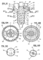
- FIGS 7 to 9 show rotor housing cover 45 including a rotor bearing 46 for receiving driver hub 12 as well as two inlets 47 and 48 for component A and B, respectively.
- rotor housing cover 45 comprises a sealing lip 49.
- Inlet 47 for component A has a larger cross-section than inlet 48 for component B and leads via a channel 50 to antechamber 32 that is partly confined by a wall 51 constituted by a recess 47A formed in the bottom plate of rotor housing cover 45.
- Smaller inlet 48 leads to the area of passage 19 at the end of antechamber 32 via a step 52 and an essentially cylindrical inlet channel 53 and inlet aperture 54.
- “In the area of the passage” means that the inlet may be located either in front of or after or opposite the passage, depending on the volumetric ratio of the components and the design of the distributor body.
- Rotor housing cover 45 is provided with grooves 33 for forming a snap connection with grooves 33 of rotor housing 25.
- Rotor housing cover 45 further comprises mechanical coding means, f. ex. in the form of a coding nose 56 directed toward inlets 47 and 48 fitting into a corresponding recess in cartridge 3, thereby allowing the attachment of the mixer to cartridge 3 in a defined orientation only, see sectional view 1E.
- Deflecting body 29 shown in Figure 6 is located at the end of inlet channel 50 such that its upper side 30 forms part of inlet channel 50, which leads into antechamber 32 essentially radially with respect to the axis of rotation.
- Distributor body 13 is arranged in antechamber 32, the latter being confined by the front side 31 of deflecting body 29 and by circular wall 51 of cover 45 shown in Figure 7 .
- Inlet aperture 54 of inlet channel 53 leads into antechamber 32 essentially radially.
- component A is pressed through inlet channel 50 into antechamber 32, guided around the axis of rotation and distributed over the entire cross-section by rotating distributor body 13, and delivered through the passage, i.e. annular gap 19, to mixing chamber 36 in the form of a thin, continuous layer on the entire circumference.
- Component B is radially delivered through inlet aperture 54 onto the rotating end portion 18 of distributor body 13 and regularly distributed, as a result of the existing flow and shearing conditions, on the circumference of end portion 18 and premixed with component A.
- mixing chamber 36 When the two premixed components have reached mixing chamber 36, they are essentially directed radially from the periphery toward the center while a further mixing effect results due to the existing flow and shearing conditions. After its passage through slotted disk portion 14, the mixture fills up post-mixing chamber 37 on the entire cross-section thereof and is subjected to another shearing and shifting process.
- the selected shape of mixing blades 15 and 16 avoids an inclusion of air and thereby prevents the formation of bubbles in the mixture.
- the mixed composition After flowing through the post-mixing chamber, the mixed composition is finally discharged through mixer outlet 38.
- Figures 10 and 11 show another embodiment of mixing rotor 60 which is a part of the mixer illustrated in Figure 12 .
- Components that are equivalent to the mixer according to Figure 1 are designated by the same reference numerals.
- the required feed pressure is further reduced by conveyor blades 17 provided on distributor body 63 in antechamber 32.
- end portion 68 of distributor body 63 has an oval shape such that a passage 69 in the form of two rotating gaps results between end portion 68 and the wall of rotor housing 25.
- Figure 12B shows the end of channel 53, leading to the edge of end portion 68 of distributor body 63 in antechamber 32 through inlet opening 54.
- End portion 68 of distributor body 63 is connected by two lateral ridges 65 to a disk portion 64 having a passage aperture 70 in the form of a slot. cf. Figures 10 and 12C .
- Passage aperture 70 extends from the edge of disk portion 64 through its center up to the area near the opposite edge thereof, cf. Figure 12C .
- disk portion 64 is connected to rotor hub 61 in such a way that a preponderantly central passage 71 from mixing chamber 36 to post-mixing chamber 37 results.
- Mixing blades 15 and 16 arranged in multiple planes on rotor hub 61, are designed for favorable flow characteristics in order to avoid the inclusion of air bubbles cf.
- Figures 1D and 12D are designed for favorable flow characteristics in order to avoid the inclusion of air bubbles cf.
- component A is pressed through inlet channel 50 into antechamber 32, guided around the axis of rotation and distributed over the entire cross-section by rotating distributor body 63, and delivered through the rotating passages 69 to mixing chamber 36 in the form of a thin, continuous layer.
- Component B is introduced into antechamber 32 radially and premixed with component A.
- the components are further mixed in combination with passage aperture 70 and central passage 71 and subsequently reach post-mixing chamber 37 where they are post-mixed and finally discharged.
- inlet opening 54 to antechamber 32 is arranged in the area of passage 19 or 69, respectively. It is conceivable to provide more than one inlet opening 54 in order to be able to introduce component B in multiple locations. It is further conceivable to arrange inlet opening 54 after passage 19 or 69, respectively, for example in such a manner that inlet channel 53 ends in mixing chamber 36.
- the optimized design of the mixing operation and the central arrangement of the different mixing elements allow a smaller pressure loss and a reduced mixer drive torque.
- the reduced friction in the medium reduces energy consumption, thereby resulting in a reduced temperature increase of the mixed material.
- the inlets and outlets are generally identical and the inlets are insertable into the outlets; but other variants are also possible where the outlets are insertable into the inlets.
- more than only one additional, smaller component may be admixed to the larger component.
- another inlet as well as another channel having an inlet opening near the passage are required.
- the depicted and disclosed characteristic features may be combined with each other as desired.
Landscapes
- Chemical & Material Sciences (AREA)
- Chemical Kinetics & Catalysis (AREA)
- Health & Medical Sciences (AREA)
- Mechanical Engineering (AREA)
- Engineering & Computer Science (AREA)
- Animal Behavior & Ethology (AREA)
- Oral & Maxillofacial Surgery (AREA)
- Public Health (AREA)
- Veterinary Medicine (AREA)
- Life Sciences & Earth Sciences (AREA)
- Epidemiology (AREA)
- Dentistry (AREA)
- General Health & Medical Sciences (AREA)
- Physics & Mathematics (AREA)
- Geometry (AREA)
- Dispersion Chemistry (AREA)
- Mixers Of The Rotary Stirring Type (AREA)
- Processing And Handling Of Plastics And Other Materials For Molding In General (AREA)
- Engine Equipment That Uses Special Cycles (AREA)
- Food-Manufacturing Devices (AREA)
- Accessories For Mixers (AREA)
Abstract
Description
- The present invention relates to a dynamic mixer according to the preamble of
claim 1 -
DE-C-42 35 736 discloses a mixer having consecutive static and dynamic mixer parts. The static mixer part is positioned before the dynamic one. The dynamic mixer part comprises a mixing cone rotor. -
WO-A 2004/080611 describes a dynamic mixer for mixing and dispensing a plurality of components from a bulk storage device. The mixer has a housing with a rotatable stator therein. The housing further having feeder channels that are configured to have a predetermined cross-section such that a pretermined amount of each component is caused to flow therethrough. The stator comprises a base and an elongate portion where the base portion comprises paddle and sweeping mix elements, and the elongate portion comprises longitudinal protrusions in axial direction of the mixer. The elongate portion of the housing comprises a plurality of molded helix threads which together with the protrusions of the stator further mix the components. The components flow from the feeder channels directly to the stator base portion where they are premixed by the mix elements of the stator base portion. The premixed components are forced to flow around the stator base portion into the stator receiving portion, i.e. the gap between the longitudinal housing and the stator elongate portion. -
EP-A-1 106 243 discloses a dynamic mixer in that for premixing the components, the mixing rotor comprises a rotor disk near the inlets whose surface facing the inlet side comprises carriers for carrying along the components to be mixed and is provided with gaps arranged in an annular shape at the circumference of the rotor disk and serving for the passage of the premixed components to the back side of the rotor disk and to the rotor hub provided with mixing elements. -
DE-A-100 43 489 discloses a dynamic mixer having a mixing element with mixing wings. A first mixing wing has inner and outer recesses and a second mixing wing has only outer recesses. Additionaly, the mixer has third mixing wings. The axially free recesses of the first and second wings are such that recesses of one wing are covered by the non-free part of the other wing. - Particularly when mixing components in different volumetric amounts as they are e.g. used for producing dental impression materials the difficulty arises that the two components should be mixed at the correct mixing ratio at the beginning of the mixing process already. If no particular measures are taken, the component whose volumetric content is smaller, e.g. a catalyst, is absent or not present in a sufficient amount at the beginning of the paste strand discharged from the mixer. The result is an unsatisfactory mixing quality such that e.g. the hardening capability of the casting compound is not ensured. Another weakness of the currently available mixers is the inclusion of air bubbles, which affects the impression quality.
-
EP-A2-1 402 940 discloses a dynamic mixer having a detour channel in order to retard the entrance of the component having the larger volumetric amount into the mixing chamber. This measure has the disadvantage that a high pressure is required for delivering that component to the mixing chamber through the detour channel, particularly if it is highly viscous. - On the background of this prior art, the object of the present invention is to provide a dynamic mixer ensuring, in a simple manner and without additional pressure losses, that both components are mixed at the correct ratio without suppressing one of the components, and that air inclusions are avoided.
- A dynamic mixer attaining this object is defined in
claim 1. The further claims, more particularlyclaim 2, define - The invention will be explained in more detail hereinafter with reference to drawings of exemplary embodiments.
- Figure 1
- shows a side elevation and partial section of a first exemplary embodiment of a mixer according to the invention that is secured to a cartridge by means of a bayonet ring,
- Figure 1A
- shows a section according to line IA-IA in
Figure 1 , without the bayonet ring, - Figure. 1B
- shows a section according to line IB-IB in
Figure 1 , without the bayonet ring, - Figure 1C
- shows a section according to line IC-IC in
Figure 1 , without the bayonet ring, - Figure 1D
- shows a section according to line ID-ID in
Figure 1 , without the bayonet ring, - Figure 1E
- shows a section according to line IE-IE in
Figure 1 , without the bayonet ring, . - Figure 2
- shows a perspective view of the mixing rotor of
Figure 1 , - Figure 2A
- shows a section of mixing
blade 15 according to line IA-IA inFigure 1D , - Figure 2B
- shows a section of
mixing blade 16 according to line IB-IB inFigure 1D , - Figure 3
- shows a lateral view and partial section of the mixing rotor of
Fig. 2 ; - Figure 4
- shows a section according to line IV-IV in
Figure 5 of the rotor housing ofFigure 1 , - Figure 5
- shows the rotor housing of
Figure 4 as seen from the inlet side, - Figure 6
- shows a perspective view of the rotor housing of
Figure 4 , - Figure 7
- shows the cover of the rotor housing of
Figure 6 as seen from the outlet side, - Figure 8
- shows a section according to line VIII-VIII in
Figure 7 , - Figure 9
- shows a perspective view of the rotor housing cover of
Figure 7 , - Figure 10
- shows a perspective view of a second exemplary embodiment of a mixing rotor,
- Figure 11
- shows a lateral view and partial section of the mixing rotor of
Fig. 10 , - Figure 12
- shows a lateral view and partial section of an assembled mixer including the mixing rotor of
Figure 11 , - Figure 12A
- shows a section according to line XIIA-XIIA in
Figure 12 , - Figure 12B
- shows a section according to line XIIB-XIIB in
Figure 12 , - Figure 12C
- shows a section according to line XIIC-XIIC in
Figure 12 , and - Figure 12D
- shows a section according to line XIID-XIID in
Figure 12 . -
Figure 1 shows the dynamic mixer which is connected tolarger outlet 1 andsmaller outlet 2 of a double cartridge 3 and secured by means of abayonet ring 4 and which serves for mixing two components in different volumetric amounts. Hereinafter, the component having the larger volumetric amount will be designated as component A and the component having the smaller volumetric amount as component B. - The mixer includes a mixing
rotor 10, arotor housing 20 androtor housing cover 30. In order to set mixingrotor 10 in rotation, it is coupled on the inlet side to a driver 5 ofmixer drive shaft 6. - As appears in
Figures 2 and 3 , the inlet end of mixingrotor 10 comprises adriver hub 12 having an opening for engagement with driver 5. -
Driver hub 12 has adistributor body 13 located on its inlet side as well as adisk portion 14 and mixingblades rotor hub 11. -
Distributor body 13 has a longitudinal cross section that is curved towardrotor hub 11.End portion 18 ofdistributor body 13 facingdisk portion 14 has a circular rim, also shown inFigure 1B . In the assembled condition of the mixer, this rim is located at a distance from the wall ofrotor housing 25 such that a gap forming apassage 19 results between the rim ofend portion 18 and the wall ofrotor housing 25. - As appears in
Figure 1C ,disk portion 14 haspassageways 20 in the form of slots extending fromrotor hub 11 to the edge ofdisk portion 14. Different passageways and shapes of the latter may alternatively be provided. - Mixing
blades rotor hub 11 in multiple planes. The shape of mixingblades rotor hub 11, mixingblades 15 having an essentially rhomboid cross-section, seeFigure 2A and mixingblades 16 having an essentially rhomboid cross-section as well (seeFigure 2B ) are alternatingly arranged. InFigure 1 , the direction of rotation of the mixing rotor is indicated by an arrow, and inFigures 2A and 2B , the direction of rotation is indicated by DR. - In
Figure 1 and.in cross-section 1D transversally to the axis of rotation of mixingrotor 10, mixingblade 16 has a rectangular shape while mixingblade 15 is curved in the shape of a hook on itsside 15a turned away from the rotational direction. In an advantageous embodiment, the end portions of all mixing blades are curved and hook-shaped on their sides turned away from the rotational direction. - Mixing
rotor 10 is enclosed in arotor housing 25 closed by arotor housing cover 45 that is illustrated inFigures 4 to 6 .Rotor housing 25 comprises a disk-shapedhousing portion 26 receivingrotor housing cover 45 as well as acylindrical housing portion 27 receivingrotor hub 11 with mixingblades bottom surface 28 of disk-shapedhousing portion 26, a deflectingbody 29 is arranged whoseupper side 30 is slanted and forms part of aninlet channel 50 for component A and whosefront side 31 forms part of anantechamber 32, cf.Figure 1 . - Disk-shaped
housing portion 26 further comprisesgrooves 33 for forming a snap connection withrotor housing cover 45 and a bearing surface 34 forbayonet ring 4.Cylindrical housing portion 27 has astep 35 on whichdisk portion 14 of mixingrotor 10 is rotatably seated wherebycylindrical housing portion 27 is divided into a mixingchamber 36 and apost-mixing chamber 37. The end ofcylindrical housing portion 27forms mixer outlet 38. -
Figures 7 to 9 showrotor housing cover 45 including a rotor bearing 46 for receivingdriver hub 12 as well as twoinlets driver hub 12,rotor housing cover 45 comprises a sealinglip 49. -
Inlet 47 for component A has a larger cross-section thaninlet 48 for component B and leads via achannel 50 toantechamber 32 that is partly confined by awall 51 constituted by arecess 47A formed in the bottom plate ofrotor housing cover 45.Smaller inlet 48 leads to the area ofpassage 19 at the end ofantechamber 32 via astep 52 and an essentiallycylindrical inlet channel 53 andinlet aperture 54. "In the area of the passage" means that the inlet may be located either in front of or after or opposite the passage, depending on the volumetric ratio of the components and the design of the distributor body. - The rim of
rotor housing cover 45 is provided withgrooves 33 for forming a snap connection withgrooves 33 ofrotor housing 25.Rotor housing cover 45 further comprises mechanical coding means, f. ex. in the form of acoding nose 56 directed towardinlets - In the attached condition of the mixer according to
Figure 1 , thelarger outlet 1 of cartridge 3 is pushed over thelarger inlet 47 of the mixer whileoutlet 2 is pushed intosmaller inlet 48 up to step 52, seeFigure 8 . - Deflecting
body 29 shown inFigure 6 is located at the end ofinlet channel 50 such that itsupper side 30 forms part ofinlet channel 50, which leads intoantechamber 32 essentially radially with respect to the axis of rotation.Distributor body 13 is arranged inantechamber 32, the latter being confined by thefront side 31 of deflectingbody 29 and bycircular wall 51 ofcover 45 shown inFigure 7 .Inlet aperture 54 ofinlet channel 53 leads intoantechamber 32 essentially radially. - In the mixing operation within the mixer according to
Figure 1 , component A is pressed throughinlet channel 50 intoantechamber 32, guided around the axis of rotation and distributed over the entire cross-section by rotatingdistributor body 13, and delivered through the passage, i.e. annulargap 19, to mixingchamber 36 in the form of a thin, continuous layer on the entire circumference. Component B is radially delivered throughinlet aperture 54 onto therotating end portion 18 ofdistributor body 13 and regularly distributed, as a result of the existing flow and shearing conditions, on the circumference ofend portion 18 and premixed with component A. - Due to the presence of an
antechamber 32, the transport of component A is temporally retarded with respect to component B so that component A reaches mixing chamber 36 a little later than component B rather than before the latter. In this manner it is ensured that the first portion of the mixture also corresponds to the desired mixing ratio.Driven distributor body 13 allows an air-free filling ofantechamber 32 with component A as well as its dynamic distribution which, in contrast to a mixer having a stationary detour channel, offers the advantage that the flow resistance remains small. Furthermore, the geometry ofinlet channel 50, leading frominlet 47 toantechamber 32 by the shortest possible way, also avoids an increase of the flow resistance so that the required delivery pressure in cartridge 3 and the stresses acting on the dispensing device are altogether low. - When the two premixed components have reached mixing
chamber 36, they are essentially directed radially from the periphery toward the center while a further mixing effect results due to the existing flow and shearing conditions. After its passage through slotteddisk portion 14, the mixture fills uppost-mixing chamber 37 on the entire cross-section thereof and is subjected to another shearing and shifting process. The selected shape of mixingblades mixer outlet 38. -
Figures 10 and 11 show another embodiment of mixingrotor 60 which is a part of the mixer illustrated inFigure 12 . Components that are equivalent to the mixer according toFigure 1 are designated by the same reference numerals. The required feed pressure is further reduced byconveyor blades 17 provided ondistributor body 63 inantechamber 32. - As appears in the sectional view of
Figure 12A ,end portion 68 ofdistributor body 63 has an oval shape such that apassage 69 in the form of two rotating gaps results betweenend portion 68 and the wall ofrotor housing 25. -
Figure 12B shows the end ofchannel 53, leading to the edge ofend portion 68 ofdistributor body 63 inantechamber 32 throughinlet opening 54. -
End portion 68 ofdistributor body 63 is connected by twolateral ridges 65 to adisk portion 64 having apassage aperture 70 in the form of a slot. cf.Figures 10 and12C .Passage aperture 70 extends from the edge ofdisk portion 64 through its center up to the area near the opposite edge thereof, cf.Figure 12C . - As further appears in
Figure 11 , at the edge of its passage aperture,disk portion 64 is connected torotor hub 61 in such a way that a preponderantlycentral passage 71 from mixingchamber 36 topost-mixing chamber 37 results. - Mixing
blades rotor hub 61, are designed for favorable flow characteristics in order to avoid the inclusion of air bubbles cf.Figures 1D and12D . - In the mixing operation within the mixer according to
Figure 12 , component A is pressed throughinlet channel 50 intoantechamber 32, guided around the axis of rotation and distributed over the entire cross-section by rotatingdistributor body 63, and delivered through therotating passages 69 to mixingchamber 36 in the form of a thin, continuous layer. Component B is introduced intoantechamber 32 radially and premixed with component A. On the outlet side of mixingchamber 36, the components are further mixed in combination withpassage aperture 70 andcentral passage 71 and subsequently reachpost-mixing chamber 37 where they are post-mixed and finally discharged. - In the mixer according to
Figures 1 and12 , inlet opening 54 toantechamber 32 is arranged in the area ofpassage inlet opening 54 in order to be able to introduce component B in multiple locations. It is further conceivable to arrangeinlet opening 54 afterpassage inlet channel 53 ends in mixingchamber 36. - The optimized design of the mixing operation and the central arrangement of the different mixing elements allow a smaller pressure loss and a reduced mixer drive torque. The reduced friction in the medium reduces energy consumption, thereby resulting in a reduced temperature increase of the mixed material.
- The represented arrangements according to
Figures 1 and12 have been described for the case that the volumes of two components are different from each other and that the component having the smaller volumetric amount is therefore delivered to the antechamber in the area of the passage in order to achieve a maximum premixing action. However, the design of the dynamic mixer offers the same advantages when both components have the same volume. In this case, the two components are symmetrically delivered to the antechamber in the upper area thereof in order to be distributed and premixed therein by the distributor body and to reach the mixing chamber through the passage. - In the embodiment having equal volumetric amounts, the inlets and outlets, respectively, are generally identical and the inlets are insertable into the outlets; but other variants are also possible where the outlets are insertable into the inlets.
- Furthermore, more than only one additional, smaller component may be admixed to the larger component. In this case, another inlet as well as another channel having an inlet opening near the passage are required. The depicted and disclosed characteristic features may be combined with each other as desired.
Claims (11)
- Dynamic mixer, comprising a rotor housing (25) in which a mixing rotor comprising a rotor hub (11) is arranged and which is closed on the inlet side by a cover (45) on which inlets for the components are arranged, the inlets (47, 48) for the components lead to an antechamber (32) that communicates with a following mixing chamber (36, 37) by at least one passage (19, 69), and the mixing rotor (10, 60) includes a distributor body (13, 63) located in the antechamber (32) for distributing the components around the axis of rotation of the mixing rotor, characterized in that the distributor body (13, 63) having a longitudinal cross section that is curved toward the rotor hub (11), and the mixing rotor (10, 60) further includes a disk portion (14, 64) having at least one passage aperture (20, 70), the disk portion is arranged after the antechamber (32) as seen in the flow direction of the components, and the mixing rotor (10, 60) is provided with mixing blades (15, 16) located in a post-mixing chamber (37) after the disk portion (14).
- Dynamic mixer according to claim 1 for mixing components in different volumetric amounts, characterized in that the inlet (47) for the first component (A) having the larger volumetric amount ends in the upper area of the antechamber (32), the inlet (48) for a second component (B) having a smaller volumetric amount ends in at least one inlet opening (54) located in the area of the passage (19, 69) to the mixing chamber (36), and the distributor body (13, 63) for distributing the two components is arranged around the axis of rotation of the mixing rotor.
- Dynamic mixer according to claim 1 for mixing components in equal volumetric amounts, characterized in that both inlets (47, 48) for the components end in the upper area of the antechamber (32), and the distributor body (13, 63) for distributing the two components is arranged around the axis of rotation of the mixing rotor.
- Mixer according to one of the preceding claims, where the passage (19, 69) is formed by a gap or multiple gaps between the circumference (18, 68) of the distributor body (13, 63) and the wall (31, 51) of the rotor housing (25) and/or of the rotor housing cover (45).
- Mixer according to one of the preceding claims, wherein the inlet opening (54) for the second component is arranged such that the latter is delivered essentially transversally to the axis of rotation of the mixing rotor (10, 60).
- Mixer according to one of the preceding claims, wherein the mixing chamber (36) is essentially formed by a wall of the rotor housing (25), of the outlet side (18, 68) of the distributor body (13, 63) and of the outlet side of the disk portion (14, 64), and wherein the passage aperture(s) (20, 70) is (are) designed such that the components, while flowing through the mixing chamber, are deflected toward the axis of rotation.
- Mixer according to claim 6, wherein the rotor housing (25) has a constricting step (35) that serves as a support for the disk portion (14, 64) and which seals the mixing chamber against a following post-mixing chamber (37) at its periphery.
- Mixer according to one of the preceding claims, wherein the distributor body (63) is provided with conveyor blades (17) arranged thereon.
- Mixer according to claim 8, wherein the mixing blades (15, 16) have an essentially rhomboid cross-section for favorable flow characteristics, two opposite mixing blades per plane or all mixing blades having a drop- or hook-shaped end on their sides turned away from the direction of rotation.
- Dispensing assembly including a double cartridge or a dispensing appliance and a dynamic mixer according to one of claims 1 to 9, the double cartridge or the dispensing appliance having outlets and the mixer inlets whose diameters are different, wherein the larger outlet is slidable over the larger inlet and the smaller outlet insertable in the smaller inlet.
- Dispensing assembly including a double cartridge or a dispensing appliance and a dynamic mixer according to one of claims 1 to 9, wherein the rotor housing cover (45) of the mixer and the cartridge (3) or the dispensing appliance comprise coding means (56) in order to allow the attachment of the mixer in only one particular orientation.
Priority Applications (2)
| Application Number | Priority Date | Filing Date | Title |
|---|---|---|---|
| PL06790929T PL1943012T3 (en) | 2005-10-07 | 2006-10-03 | Dynamic mixer |
| SI200630617T SI1943012T1 (en) | 2005-10-07 | 2006-10-03 | Dynamic mixer |
Applications Claiming Priority (2)
| Application Number | Priority Date | Filing Date | Title |
|---|---|---|---|
| CH16192005 | 2005-10-07 | ||
| PCT/CH2006/000538 WO2007041878A1 (en) | 2005-10-07 | 2006-10-03 | Dynamic mixer |
Publications (2)
| Publication Number | Publication Date |
|---|---|
| EP1943012A1 EP1943012A1 (en) | 2008-07-16 |
| EP1943012B1 true EP1943012B1 (en) | 2010-01-13 |
Family
ID=35470866
Family Applications (1)
| Application Number | Title | Priority Date | Filing Date |
|---|---|---|---|
| EP06790929A Active EP1943012B1 (en) | 2005-10-07 | 2006-10-03 | Dynamic mixer |
Country Status (17)
| Country | Link |
|---|---|
| US (1) | US8313232B2 (en) |
| EP (1) | EP1943012B1 (en) |
| JP (1) | JP4943441B2 (en) |
| KR (1) | KR101275062B1 (en) |
| CN (1) | CN101282781B (en) |
| AT (1) | ATE454933T1 (en) |
| AU (1) | AU2006301860B2 (en) |
| BR (1) | BRPI0616966B8 (en) |
| CA (1) | CA2624819C (en) |
| DE (1) | DE602006011772D1 (en) |
| DK (1) | DK1943012T3 (en) |
| ES (1) | ES2337833T3 (en) |
| IL (1) | IL190615A (en) |
| PL (1) | PL1943012T3 (en) |
| RU (1) | RU2414956C2 (en) |
| SI (1) | SI1943012T1 (en) |
| WO (1) | WO2007041878A1 (en) |
Cited By (5)
| Publication number | Priority date | Publication date | Assignee | Title |
|---|---|---|---|---|
| WO2012055926A1 (en) | 2010-10-26 | 2012-05-03 | Kettenbach Gmbh & Co. Kg | Double cartridge, mixer therefor and combination of double cartridge and mixer |
| WO2013026722A1 (en) | 2011-08-24 | 2013-02-28 | Kettenbach Gmbh & Co. Kg | Mixer |
| WO2013026716A1 (en) | 2011-08-24 | 2013-02-28 | Kettenbach Gmbh & Co. Kg | System composed of cartridges and mixers |
| WO2019020768A1 (en) | 2017-07-28 | 2019-01-31 | Kettenbach Gmbh & Co. Kg | Mixer having compensation duct and/or holding chamber |
| DE102017117199A1 (en) | 2017-07-28 | 2019-01-31 | 3lmed GmbH | Mixer with compensation channel and / or stowage chamber |
Families Citing this family (29)
| Publication number | Priority date | Publication date | Assignee | Title |
|---|---|---|---|---|
| DE202005005833U1 (en) * | 2005-02-25 | 2005-06-23 | Vosschemie Gmbh | Dispenser and mixer for two component reactive resin-fillers e.g. for repair of automobile bodywork |
| DE102006038897B4 (en) * | 2006-08-18 | 2014-10-16 | Mühlbauer Technology Gmbh | Apparatus for generating a multicomponent mass |
| EP2102076B1 (en) | 2006-12-15 | 2011-10-26 | 3M Innovative Properties Company | Mixing and dispensing curable multi-component materials |
| US20080267005A1 (en) * | 2007-04-24 | 2008-10-30 | Tyco Healthcare Group Lp | Applicator system and method of use |
| CH699611B1 (en) * | 2007-05-01 | 2010-04-15 | Sulzer Mixpac Ag | Tabletop device for mixing and dispensing of multicomponent compositions. |
| EP2190563B1 (en) * | 2007-09-10 | 2011-09-28 | Sulzer Mixpac AG | Dynamic mixer |
| DE102008008852A1 (en) * | 2008-02-13 | 2009-08-27 | Dibau Gmbh & Co. Kg | Mixing device i.e. disposable article, for mixing components of e.g. viscous medium, during window and facade construction, has chambers provided in housing in flow direction of components, and rotatable mixing vane arranged in chambers |
| DE102008008964A1 (en) * | 2008-02-13 | 2009-08-27 | Dibau Gmbh & Co. Kg | Mixing device i.e. disposable article, for mixing components of e.g. viscous medium, during window and facade construction, has chambers provided in housing in flow direction of components, and rotatable mixing vane arranged in chambers |
| ES2338620B1 (en) * | 2008-04-25 | 2011-02-18 | Instalaciones Industriales Grau, S.L. | FLUID MIXING DEVICE FOR ROTOR OF FIXED AND MOBILE ASPAS. |
| GB0915007D0 (en) † | 2009-08-28 | 2009-09-30 | 3M Innovative Properties Co | Mixer and system for mixing and dispensing material |
| EP2399666B1 (en) * | 2010-06-22 | 2013-02-20 | 3M Innovative Properties Company | Mixer for preparing a dental material, and system comprising the same |
| EP2441413A1 (en) * | 2010-10-18 | 2012-04-18 | 3M Innovative Properties Company | A mixer for forming a dental material, a system comprising the mixer, and a method of mounting the mixer |
| RU2581087C2 (en) * | 2011-02-28 | 2016-04-10 | Зульцер Микспэк Аг | Dynamic mixer |
| RU2578307C2 (en) | 2011-02-28 | 2016-03-27 | Зульцер Микспэк Аг | Dynamic mixer and use thereof |
| CN104645844A (en) * | 2011-03-15 | 2015-05-27 | 中国纺织科学研究院 | Dynamic mixer |
| CN102160971A (en) * | 2011-03-15 | 2011-08-24 | 中国纺织科学研究院 | Dynamic mixer |
| EP2520360B1 (en) * | 2011-05-02 | 2014-07-16 | Sulzer Mixpac AG | Mixer for mixing at least two flowable components, and application device |
| KR101091062B1 (en) * | 2011-07-04 | 2011-12-08 | (주) 세일덴텍 | A mixing tip of automatic style dental impression material |
| IN2012DE01330A (en) * | 2011-07-22 | 2015-09-25 | Sulzer Mixpac Ag | |
| CN102814131A (en) * | 2012-07-10 | 2012-12-12 | 广饶彤鑫工贸有限公司 | Twin-spiral mixer |
| US8960501B2 (en) * | 2012-10-23 | 2015-02-24 | Nordson Corporation | Dispensing assembly and method for dispensing a mixed fluid |
| KR102023143B1 (en) * | 2012-11-08 | 2019-09-19 | 술저 믹스팩 아게 | Cartridge for at least two flowable components |
| KR101698170B1 (en) | 2013-07-24 | 2017-01-19 | (주) 디유티코리아 | Turbo dynamic mixer with variable multiple-stage impeller |
| KR101406068B1 (en) * | 2013-09-05 | 2014-06-11 | (주)디엑스엠 | Impression mixing tip |
| US9827539B2 (en) * | 2015-07-31 | 2017-11-28 | Phillip Phung-I Ho | Dynamic mixer head |
| CN105921089B (en) * | 2016-04-27 | 2018-06-26 | 沈阳派司钛设备有限公司 | A kind of hydrogen fluoride pre-reactor helical blade |
| US10792627B2 (en) * | 2018-05-08 | 2020-10-06 | Sensia Llc | Fluid mixing systems and methods |
| DE102019119160A1 (en) | 2019-07-15 | 2021-01-21 | Kulzer Gmbh | Dynamic mixer with adjustable feed channels |
| CN112076649A (en) * | 2020-09-22 | 2020-12-15 | 安徽富邦药业有限公司 | A join in marriage and strain device for production of compound amino acid injection |
Family Cites Families (16)
| Publication number | Priority date | Publication date | Assignee | Title |
|---|---|---|---|---|
| DE4235736C1 (en) | 1992-10-23 | 1994-03-24 | Bergmann Franz Josef | Device for mixing and distributing paste pulp - comprises combination of static mixer with channels for the breakdown and pre-distribution of the pulp into a number of thin strands |
| US5424054A (en) * | 1993-05-21 | 1995-06-13 | International Business Machines Corporation | Carbon fibers and method for their production |
| WO1995026925A1 (en) * | 1994-03-30 | 1995-10-12 | Massachusetts Institute Of Technology | Production of fullerenic nanostructures in flames |
| JPH09115334A (en) * | 1995-10-23 | 1997-05-02 | Mitsubishi Materiais Corp | Transparent conductive film and composition for film formation |
| US6221330B1 (en) * | 1997-08-04 | 2001-04-24 | Hyperion Catalysis International Inc. | Process for producing single wall nanotubes using unsupported metal catalysts |
| DE29923938U1 (en) * | 1998-10-14 | 2001-07-19 | Kettenbach GmbH & Co. KG, 35713 Eschenburg | Device for discharging a pasty two-component mixture |
| DE29907573U1 (en) * | 1999-04-28 | 2000-09-07 | Ernst Mühlbauer KG, 22547 Hamburg | Dynamic mixer for dental impression materials |
| ATE330700T1 (en) | 1999-12-02 | 2006-07-15 | Mixpac Systems Ag | DYNAMIC MIXER. |
| US6443612B1 (en) * | 1999-12-02 | 2002-09-03 | Wilhelm A. Keller | Dynamic mixer |
| EP1110599B1 (en) * | 1999-12-23 | 2003-04-09 | Ernst Mühlbauer GmbH & Co.KG | Dynamic mixer for dental impression pastes |
| ATE384094T1 (en) * | 2000-03-28 | 2008-02-15 | Univ Oklahoma State | ARRANGEMENT OF SELF-SUPPORTING FILMS USING A LAYER-BY-LAY PROCESS |
| DE10043489A1 (en) * | 2000-09-01 | 2002-03-14 | Heraeus Kulzer Gmbh & Co Kg | Dynamic mixer used for mixing viscous multiple component materials, especially dental material has a mixing element with mixing wings arranged on the side facing the closing part |
| KR20040030553A (en) * | 2001-03-26 | 2004-04-09 | 에이코스 인코포레이티드 | Coatings containing carbon nanotubes |
| DE20302987U1 (en) * | 2003-02-24 | 2003-04-24 | Ernst Muehlbauer Gmbh & Co Kg | Dynamic mixer, used for mixing components of dentistry compositions, comprises mixing tube, rotor delimiting annular mixing channel, and wall with inlet openings for components |
| EP1599292B1 (en) * | 2003-03-06 | 2007-08-15 | Dentsply International, Inc. | Dispensing and mixing tip |
| JP4413561B2 (en) * | 2003-09-01 | 2010-02-10 | 株式会社ジーシー | Dental impression mixing mixer |
-
2006
- 2006-10-03 PL PL06790929T patent/PL1943012T3/en unknown
- 2006-10-03 EP EP06790929A patent/EP1943012B1/en active Active
- 2006-10-03 ES ES06790929T patent/ES2337833T3/en active Active
- 2006-10-03 AT AT06790929T patent/ATE454933T1/en active
- 2006-10-03 DE DE602006011772T patent/DE602006011772D1/en active Active
- 2006-10-03 BR BRPI0616966A patent/BRPI0616966B8/en active IP Right Grant
- 2006-10-03 RU RU2008118148/05A patent/RU2414956C2/en not_active IP Right Cessation
- 2006-10-03 CN CN2006800372224A patent/CN101282781B/en active Active
- 2006-10-03 JP JP2008533844A patent/JP4943441B2/en active Active
- 2006-10-03 CA CA2624819A patent/CA2624819C/en not_active Expired - Fee Related
- 2006-10-03 US US12/083,145 patent/US8313232B2/en active Active
- 2006-10-03 AU AU2006301860A patent/AU2006301860B2/en not_active Ceased
- 2006-10-03 SI SI200630617T patent/SI1943012T1/en unknown
- 2006-10-03 DK DK06790929.1T patent/DK1943012T3/en active
- 2006-10-03 WO PCT/CH2006/000538 patent/WO2007041878A1/en active Application Filing
-
2008
- 2008-04-03 IL IL190615A patent/IL190615A/en not_active IP Right Cessation
- 2008-04-17 KR KR1020087009220A patent/KR101275062B1/en active IP Right Grant
Cited By (9)
| Publication number | Priority date | Publication date | Assignee | Title |
|---|---|---|---|---|
| WO2012055926A1 (en) | 2010-10-26 | 2012-05-03 | Kettenbach Gmbh & Co. Kg | Double cartridge, mixer therefor and combination of double cartridge and mixer |
| WO2013026722A1 (en) | 2011-08-24 | 2013-02-28 | Kettenbach Gmbh & Co. Kg | Mixer |
| WO2013026716A1 (en) | 2011-08-24 | 2013-02-28 | Kettenbach Gmbh & Co. Kg | System composed of cartridges and mixers |
| US9272252B2 (en) | 2011-08-24 | 2016-03-01 | Kettenbach Gmbh & Co. Kg | System composed of cartridges and mixers |
| US9463079B2 (en) | 2011-08-24 | 2016-10-11 | Kettenbach Gmbh & Co. Kg | Mixer |
| WO2019020768A1 (en) | 2017-07-28 | 2019-01-31 | Kettenbach Gmbh & Co. Kg | Mixer having compensation duct and/or holding chamber |
| DE102017117199A1 (en) | 2017-07-28 | 2019-01-31 | 3lmed GmbH | Mixer with compensation channel and / or stowage chamber |
| US11717794B2 (en) | 2017-07-28 | 2023-08-08 | 3lmed GmbH | Mixer |
| US11986785B2 (en) | 2017-07-28 | 2024-05-21 | 3lmed GmbH | Mixer having compensation channel and/or reservoir chamber |
Also Published As
| Publication number | Publication date |
|---|---|
| US8313232B2 (en) | 2012-11-20 |
| RU2008118148A (en) | 2009-11-20 |
| PL1943012T3 (en) | 2010-06-30 |
| US20090296516A1 (en) | 2009-12-03 |
| JP2009509758A (en) | 2009-03-12 |
| EP1943012A1 (en) | 2008-07-16 |
| IL190615A (en) | 2011-06-30 |
| CN101282781A (en) | 2008-10-08 |
| BRPI0616966A2 (en) | 2011-07-05 |
| DK1943012T3 (en) | 2010-03-29 |
| SI1943012T1 (en) | 2010-05-31 |
| IL190615A0 (en) | 2008-11-03 |
| AU2006301860B2 (en) | 2010-11-11 |
| BRPI0616966B8 (en) | 2023-03-21 |
| CA2624819A1 (en) | 2007-04-19 |
| ES2337833T3 (en) | 2010-04-29 |
| KR20080046744A (en) | 2008-05-27 |
| DE602006011772D1 (en) | 2010-03-04 |
| BRPI0616966B1 (en) | 2017-12-05 |
| CA2624819C (en) | 2014-07-08 |
| JP4943441B2 (en) | 2012-05-30 |
| ATE454933T1 (en) | 2010-01-15 |
| RU2414956C2 (en) | 2011-03-27 |
| AU2006301860A1 (en) | 2007-04-19 |
| WO2007041878A1 (en) | 2007-04-19 |
| CN101282781B (en) | 2010-06-23 |
| KR101275062B1 (en) | 2013-06-14 |
Similar Documents
| Publication | Publication Date | Title |
|---|---|---|
| EP1943012B1 (en) | Dynamic mixer | |
| US9656224B2 (en) | Dynamic mixer | |
| TWI568492B (en) | Dynamic mixer | |
| JP5389032B2 (en) | Dynamic mixer | |
| JP4814423B2 (en) | Dynamic mixer | |
| US20010005338A1 (en) | Dynamic mixer for dental impression compounds | |
| US20090207685A1 (en) | Mixer | |
| US7320541B2 (en) | Mixer element for a mixer for multi-component pastes, and mixer using the same | |
| EP1802385B1 (en) | Mixer for multi-component pastes, kit, and method of mixing paste components | |
| JP2003516840A (en) | Dynamic mixer | |
| KR20070058633A (en) | Mixer for multi-component pastes, kit, and method of mixing paste components | |
| RU2521648C1 (en) | Mixer for preparing dental material and system containing it | |
| US20080264809A1 (en) | Method for the Production of Dental Moulding Materials and Device Therefor | |
| CN113646070B (en) | Dynamic mixer, dispensing assembly and method of dispensing multicomponent material from a cartridge | |
| MX2008004420A (en) | Dynamic mixer | |
| JP3727183B2 (en) | Paste kneading equipment | |
| JP3793671B2 (en) | Paste kneading equipment |
Legal Events
| Date | Code | Title | Description |
|---|---|---|---|
| PUAI | Public reference made under article 153(3) epc to a published international application that has entered the european phase |
Free format text: ORIGINAL CODE: 0009012 |
|
| 17P | Request for examination filed |
Effective date: 20080507 |
|
| AK | Designated contracting states |
Kind code of ref document: A1 Designated state(s): AT BE BG CH CY CZ DE DK EE ES FI FR GB GR HU IE IS IT LI LT LU LV MC NL PL PT RO SE SI SK TR |
|
| 17Q | First examination report despatched |
Effective date: 20080805 |
|
| GRAP | Despatch of communication of intention to grant a patent |
Free format text: ORIGINAL CODE: EPIDOSNIGR1 |
|
| RAP1 | Party data changed (applicant data changed or rights of an application transferred) |
Owner name: SULZER MIXPAC AG |
|
| GRAS | Grant fee paid |
Free format text: ORIGINAL CODE: EPIDOSNIGR3 |
|
| GRAA | (expected) grant |
Free format text: ORIGINAL CODE: 0009210 |
|
| AK | Designated contracting states |
Kind code of ref document: B1 Designated state(s): AT BE BG CH CY CZ DE DK EE ES FI FR GB GR HU IE IS IT LI LT LU LV MC NL PL PT RO SE SI SK TR |
|
| REG | Reference to a national code |
Ref country code: GB Ref legal event code: FG4D |
|
| REG | Reference to a national code |
Ref country code: CH Ref legal event code: NV Representative=s name: SULZER MANAGEMENT AG PATENTABTEILUNG/0067 Ref country code: CH Ref legal event code: EP |
|
| REG | Reference to a national code |
Ref country code: IE Ref legal event code: FG4D |
|
| REF | Corresponds to: |
Ref document number: 602006011772 Country of ref document: DE Date of ref document: 20100304 Kind code of ref document: P |
|
| REG | Reference to a national code |
Ref country code: DK Ref legal event code: T3 |
|
| REG | Reference to a national code |
Ref country code: SE Ref legal event code: TRGR |
|
| REG | Reference to a national code |
Ref country code: NL Ref legal event code: T3 |
|
| REG | Reference to a national code |
Ref country code: ES Ref legal event code: FG2A Ref document number: 2337833 Country of ref document: ES Kind code of ref document: T3 |
|
| LTIE | Lt: invalidation of european patent or patent extension |
Effective date: 20100113 |
|
| PG25 | Lapsed in a contracting state [announced via postgrant information from national office to epo] |
Ref country code: LT Free format text: LAPSE BECAUSE OF FAILURE TO SUBMIT A TRANSLATION OF THE DESCRIPTION OR TO PAY THE FEE WITHIN THE PRESCRIBED TIME-LIMIT Effective date: 20100113 Ref country code: PT Free format text: LAPSE BECAUSE OF FAILURE TO SUBMIT A TRANSLATION OF THE DESCRIPTION OR TO PAY THE FEE WITHIN THE PRESCRIBED TIME-LIMIT Effective date: 20100513 Ref country code: IS Free format text: LAPSE BECAUSE OF FAILURE TO SUBMIT A TRANSLATION OF THE DESCRIPTION OR TO PAY THE FEE WITHIN THE PRESCRIBED TIME-LIMIT Effective date: 20100513 |
|
| PG25 | Lapsed in a contracting state [announced via postgrant information from national office to epo] |
Ref country code: LV Free format text: LAPSE BECAUSE OF FAILURE TO SUBMIT A TRANSLATION OF THE DESCRIPTION OR TO PAY THE FEE WITHIN THE PRESCRIBED TIME-LIMIT Effective date: 20100113 Ref country code: FI Free format text: LAPSE BECAUSE OF FAILURE TO SUBMIT A TRANSLATION OF THE DESCRIPTION OR TO PAY THE FEE WITHIN THE PRESCRIBED TIME-LIMIT Effective date: 20100113 |
|
| PG25 | Lapsed in a contracting state [announced via postgrant information from national office to epo] |
Ref country code: EE Free format text: LAPSE BECAUSE OF FAILURE TO SUBMIT A TRANSLATION OF THE DESCRIPTION OR TO PAY THE FEE WITHIN THE PRESCRIBED TIME-LIMIT Effective date: 20100113 Ref country code: GR Free format text: LAPSE BECAUSE OF FAILURE TO SUBMIT A TRANSLATION OF THE DESCRIPTION OR TO PAY THE FEE WITHIN THE PRESCRIBED TIME-LIMIT Effective date: 20100414 Ref country code: CY Free format text: LAPSE BECAUSE OF FAILURE TO SUBMIT A TRANSLATION OF THE DESCRIPTION OR TO PAY THE FEE WITHIN THE PRESCRIBED TIME-LIMIT Effective date: 20100113 Ref country code: RO Free format text: LAPSE BECAUSE OF FAILURE TO SUBMIT A TRANSLATION OF THE DESCRIPTION OR TO PAY THE FEE WITHIN THE PRESCRIBED TIME-LIMIT Effective date: 20100113 Ref country code: BE Free format text: LAPSE BECAUSE OF FAILURE TO SUBMIT A TRANSLATION OF THE DESCRIPTION OR TO PAY THE FEE WITHIN THE PRESCRIBED TIME-LIMIT Effective date: 20100113 |
|
| PLBE | No opposition filed within time limit |
Free format text: ORIGINAL CODE: 0009261 |
|
| STAA | Information on the status of an ep patent application or granted ep patent |
Free format text: STATUS: NO OPPOSITION FILED WITHIN TIME LIMIT |
|
| PG25 | Lapsed in a contracting state [announced via postgrant information from national office to epo] |
Ref country code: BG Free format text: LAPSE BECAUSE OF FAILURE TO SUBMIT A TRANSLATION OF THE DESCRIPTION OR TO PAY THE FEE WITHIN THE PRESCRIBED TIME-LIMIT Effective date: 20100413 Ref country code: SK Free format text: LAPSE BECAUSE OF FAILURE TO SUBMIT A TRANSLATION OF THE DESCRIPTION OR TO PAY THE FEE WITHIN THE PRESCRIBED TIME-LIMIT Effective date: 20100113 |
|
| 26N | No opposition filed |
Effective date: 20101014 |
|
| PG25 | Lapsed in a contracting state [announced via postgrant information from national office to epo] |
Ref country code: MC Free format text: LAPSE BECAUSE OF NON-PAYMENT OF DUE FEES Effective date: 20101031 |
|
| PG25 | Lapsed in a contracting state [announced via postgrant information from national office to epo] |
Ref country code: IE Free format text: LAPSE BECAUSE OF NON-PAYMENT OF DUE FEES Effective date: 20101003 |
|
| PG25 | Lapsed in a contracting state [announced via postgrant information from national office to epo] |
Ref country code: HU Free format text: LAPSE BECAUSE OF FAILURE TO SUBMIT A TRANSLATION OF THE DESCRIPTION OR TO PAY THE FEE WITHIN THE PRESCRIBED TIME-LIMIT Effective date: 20100714 Ref country code: LU Free format text: LAPSE BECAUSE OF NON-PAYMENT OF DUE FEES Effective date: 20101003 |
|
| PGFP | Annual fee paid to national office [announced via postgrant information from national office to epo] |
Ref country code: TR Payment date: 20121001 Year of fee payment: 7 |
|
| REG | Reference to a national code |
Ref country code: CH Ref legal event code: NV Representative=s name: DR. GRAF AND PARTNER AG INTELLECTUAL PROPERTY, CH |
|
| PG25 | Lapsed in a contracting state [announced via postgrant information from national office to epo] |
Ref country code: TR Free format text: LAPSE BECAUSE OF NON-PAYMENT OF DUE FEES Effective date: 20131003 |
|
| REG | Reference to a national code |
Ref country code: FR Ref legal event code: PLFP Year of fee payment: 10 |
|
| PGFP | Annual fee paid to national office [announced via postgrant information from national office to epo] |
Ref country code: PL Payment date: 20150922 Year of fee payment: 10 |
|
| PGFP | Annual fee paid to national office [announced via postgrant information from national office to epo] |
Ref country code: DK Payment date: 20151021 Year of fee payment: 10 |
|
| PGFP | Annual fee paid to national office [announced via postgrant information from national office to epo] |
Ref country code: SE Payment date: 20151021 Year of fee payment: 10 Ref country code: SI Payment date: 20150923 Year of fee payment: 10 Ref country code: CZ Payment date: 20151001 Year of fee payment: 10 Ref country code: AT Payment date: 20151022 Year of fee payment: 10 Ref country code: NL Payment date: 20151021 Year of fee payment: 10 |
|
| REG | Reference to a national code |
Ref country code: FR Ref legal event code: PLFP Year of fee payment: 11 |
|
| REG | Reference to a national code |
Ref country code: DK Ref legal event code: EBP Effective date: 20161031 |
|
| PG25 | Lapsed in a contracting state [announced via postgrant information from national office to epo] |
Ref country code: CZ Free format text: LAPSE BECAUSE OF NON-PAYMENT OF DUE FEES Effective date: 20161003 |
|
| REG | Reference to a national code |
Ref country code: NL Ref legal event code: MM Effective date: 20161101 |
|
| REG | Reference to a national code |
Ref country code: AT Ref legal event code: MM01 Ref document number: 454933 Country of ref document: AT Kind code of ref document: T Effective date: 20161003 |
|
| REG | Reference to a national code |
Ref country code: SI Ref legal event code: KO00 Effective date: 20170609 |
|
| PG25 | Lapsed in a contracting state [announced via postgrant information from national office to epo] |
Ref country code: SE Free format text: LAPSE BECAUSE OF NON-PAYMENT OF DUE FEES Effective date: 20161004 Ref country code: AT Free format text: LAPSE BECAUSE OF NON-PAYMENT OF DUE FEES Effective date: 20161003 Ref country code: NL Free format text: LAPSE BECAUSE OF NON-PAYMENT OF DUE FEES Effective date: 20161101 Ref country code: SI Free format text: LAPSE BECAUSE OF NON-PAYMENT OF DUE FEES Effective date: 20161004 |
|
| REG | Reference to a national code |
Ref country code: FR Ref legal event code: PLFP Year of fee payment: 12 |
|
| PG25 | Lapsed in a contracting state [announced via postgrant information from national office to epo] |
Ref country code: DK Free format text: LAPSE BECAUSE OF NON-PAYMENT OF DUE FEES Effective date: 20161031 |
|
| PGFP | Annual fee paid to national office [announced via postgrant information from national office to epo] |
Ref country code: GB Payment date: 20171101 Year of fee payment: 15 |
|
| PG25 | Lapsed in a contracting state [announced via postgrant information from national office to epo] |
Ref country code: PL Free format text: LAPSE BECAUSE OF NON-PAYMENT OF DUE FEES Effective date: 20161003 |
|
| REG | Reference to a national code |
Ref country code: FR Ref legal event code: PLFP Year of fee payment: 13 |
|
| REG | Reference to a national code |
Ref country code: CH Ref legal event code: PL |
|
| PG25 | Lapsed in a contracting state [announced via postgrant information from national office to epo] |
Ref country code: CH Free format text: LAPSE BECAUSE OF NON-PAYMENT OF DUE FEES Effective date: 20181031 Ref country code: LI Free format text: LAPSE BECAUSE OF NON-PAYMENT OF DUE FEES Effective date: 20181031 |
|
| PGFP | Annual fee paid to national office [announced via postgrant information from national office to epo] |
Ref country code: ES Payment date: 20191122 Year of fee payment: 14 Ref country code: IT Payment date: 20191028 Year of fee payment: 14 |
|
| GBPC | Gb: european patent ceased through non-payment of renewal fee |
Effective date: 20201003 |
|
| PG25 | Lapsed in a contracting state [announced via postgrant information from national office to epo] |
Ref country code: GB Free format text: LAPSE BECAUSE OF NON-PAYMENT OF DUE FEES Effective date: 20201003 |
|
| PG25 | Lapsed in a contracting state [announced via postgrant information from national office to epo] |
Ref country code: IT Free format text: LAPSE BECAUSE OF NON-PAYMENT OF DUE FEES Effective date: 20201003 |
|
| REG | Reference to a national code |
Ref country code: DE Ref legal event code: R079 Ref document number: 602006011772 Country of ref document: DE Free format text: PREVIOUS MAIN CLASS: B01F0013000000 Ipc: B01F0033000000 |
|
| REG | Reference to a national code |
Ref country code: ES Ref legal event code: FD2A Effective date: 20220119 |
|
| PG25 | Lapsed in a contracting state [announced via postgrant information from national office to epo] |
Ref country code: ES Free format text: LAPSE BECAUSE OF NON-PAYMENT OF DUE FEES Effective date: 20201004 |
|
| REG | Reference to a national code |
Ref country code: DE Ref legal event code: R081 Ref document number: 602006011772 Country of ref document: DE Owner name: MEDMIX SWITZERLAND AG, CH Free format text: FORMER OWNER: SULZER MIXPAC AG, HAAG, CH |
|
| PGFP | Annual fee paid to national office [announced via postgrant information from national office to epo] |
Ref country code: FR Payment date: 20221028 Year of fee payment: 17 |
|
| PGFP | Annual fee paid to national office [announced via postgrant information from national office to epo] |
Ref country code: DE Payment date: 20231020 Year of fee payment: 18 |
|
| PG25 | Lapsed in a contracting state [announced via postgrant information from national office to epo] |
Ref country code: FR Free format text: LAPSE BECAUSE OF NON-PAYMENT OF DUE FEES Effective date: 20231031 |