EP1942786B1 - Endoscope reprocessor connectivity method - Google Patents
Endoscope reprocessor connectivity method Download PDFInfo
- Publication number
- EP1942786B1 EP1942786B1 EP06850420.8A EP06850420A EP1942786B1 EP 1942786 B1 EP1942786 B1 EP 1942786B1 EP 06850420 A EP06850420 A EP 06850420A EP 1942786 B1 EP1942786 B1 EP 1942786B1
- Authority
- EP
- European Patent Office
- Prior art keywords
- channel
- endoscope
- pressure
- time
- reprocessor
- Prior art date
- Legal status (The legal status is an assumption and is not a legal conclusion. Google has not performed a legal analysis and makes no representation as to the accuracy of the status listed.)
- Active
Links
- 238000000034 method Methods 0.000 title claims description 21
- 239000012530 fluid Substances 0.000 claims description 35
- 238000012360 testing method Methods 0.000 claims description 19
- 239000007788 liquid Substances 0.000 claims description 14
- XLYOFNOQVPJJNP-UHFFFAOYSA-N water Substances O XLYOFNOQVPJJNP-UHFFFAOYSA-N 0.000 claims description 14
- 238000012958 reprocessing Methods 0.000 claims description 10
- 238000012544 monitoring process Methods 0.000 claims description 9
- 238000004140 cleaning Methods 0.000 description 8
- 230000000249 desinfective effect Effects 0.000 description 8
- 238000001574 biopsy Methods 0.000 description 5
- 238000001514 detection method Methods 0.000 description 4
- 230000008878 coupling Effects 0.000 description 3
- 238000010168 coupling process Methods 0.000 description 3
- 238000005859 coupling reaction Methods 0.000 description 3
- 230000037361 pathway Effects 0.000 description 3
- 238000013459 approach Methods 0.000 description 2
- 230000000903 blocking effect Effects 0.000 description 2
- 238000004891 communication Methods 0.000 description 2
- 239000000645 desinfectant Substances 0.000 description 2
- 238000001035 drying Methods 0.000 description 2
- 238000000926 separation method Methods 0.000 description 2
- 239000000344 soap Substances 0.000 description 2
- LFQSCWFLJHTTHZ-UHFFFAOYSA-N Ethanol Chemical compound CCO LFQSCWFLJHTTHZ-UHFFFAOYSA-N 0.000 description 1
- 230000003213 activating effect Effects 0.000 description 1
- 230000003247 decreasing effect Effects 0.000 description 1
- 238000010586 diagram Methods 0.000 description 1
- 238000005259 measurement Methods 0.000 description 1
- 230000003446 memory effect Effects 0.000 description 1
- 238000005086 pumping Methods 0.000 description 1
- 239000012858 resilient material Substances 0.000 description 1
- 230000004044 response Effects 0.000 description 1
- 230000001954 sterilising effect Effects 0.000 description 1
- 238000004659 sterilization and disinfection Methods 0.000 description 1
- 238000011144 upstream manufacturing Methods 0.000 description 1
- 238000005406 washing Methods 0.000 description 1
Images


Classifications
-
- A—HUMAN NECESSITIES
- A61—MEDICAL OR VETERINARY SCIENCE; HYGIENE
- A61L—METHODS OR APPARATUS FOR STERILISING MATERIALS OR OBJECTS IN GENERAL; DISINFECTION, STERILISATION OR DEODORISATION OF AIR; CHEMICAL ASPECTS OF BANDAGES, DRESSINGS, ABSORBENT PADS OR SURGICAL ARTICLES; MATERIALS FOR BANDAGES, DRESSINGS, ABSORBENT PADS OR SURGICAL ARTICLES
- A61L2/00—Methods or apparatus for disinfecting or sterilising materials or objects other than foodstuffs or contact lenses; Accessories therefor
- A61L2/16—Methods or apparatus for disinfecting or sterilising materials or objects other than foodstuffs or contact lenses; Accessories therefor using chemical substances
- A61L2/18—Liquid substances or solutions comprising solids or dissolved gases
-
- A—HUMAN NECESSITIES
- A61—MEDICAL OR VETERINARY SCIENCE; HYGIENE
- A61B—DIAGNOSIS; SURGERY; IDENTIFICATION
- A61B1/00—Instruments for performing medical examinations of the interior of cavities or tubes of the body by visual or photographical inspection, e.g. endoscopes; Illuminating arrangements therefor
- A61B1/00002—Operational features of endoscopes
- A61B1/00057—Operational features of endoscopes provided with means for testing or calibration
-
- A—HUMAN NECESSITIES
- A61—MEDICAL OR VETERINARY SCIENCE; HYGIENE
- A61B—DIAGNOSIS; SURGERY; IDENTIFICATION
- A61B1/00—Instruments for performing medical examinations of the interior of cavities or tubes of the body by visual or photographical inspection, e.g. endoscopes; Illuminating arrangements therefor
- A61B1/12—Instruments for performing medical examinations of the interior of cavities or tubes of the body by visual or photographical inspection, e.g. endoscopes; Illuminating arrangements therefor with cooling or rinsing arrangements
- A61B1/121—Instruments for performing medical examinations of the interior of cavities or tubes of the body by visual or photographical inspection, e.g. endoscopes; Illuminating arrangements therefor with cooling or rinsing arrangements provided with means for cleaning post-use
- A61B1/125—Instruments for performing medical examinations of the interior of cavities or tubes of the body by visual or photographical inspection, e.g. endoscopes; Illuminating arrangements therefor with cooling or rinsing arrangements provided with means for cleaning post-use using fluid circuits
-
- A—HUMAN NECESSITIES
- A61—MEDICAL OR VETERINARY SCIENCE; HYGIENE
- A61B—DIAGNOSIS; SURGERY; IDENTIFICATION
- A61B90/00—Instruments, implements or accessories specially adapted for surgery or diagnosis and not covered by any of the groups A61B1/00 - A61B50/00, e.g. for luxation treatment or for protecting wound edges
- A61B90/70—Cleaning devices specially adapted for surgical instruments
- A61B2090/701—Cleaning devices specially adapted for surgical instruments for flexible tubular instruments, e.g. endoscopes
-
- A—HUMAN NECESSITIES
- A61—MEDICAL OR VETERINARY SCIENCE; HYGIENE
- A61B—DIAGNOSIS; SURGERY; IDENTIFICATION
- A61B90/00—Instruments, implements or accessories specially adapted for surgery or diagnosis and not covered by any of the groups A61B1/00 - A61B50/00, e.g. for luxation treatment or for protecting wound edges
- A61B90/70—Cleaning devices specially adapted for surgical instruments
Definitions
- This invention relates to the field of reprocessors for devices, particularly medical devices, and more particularly to endoscopes and the like having one or more internal passageways which are to be cleaned and disinfected by an automatic reprocessor. Reprocessing includes washing, disinfecting and drying such devices.
- endoscope and “endoscopes” refer not only to endoscopes, but also to similar devices (including accessories) which may suitably be reprocessed using an Automatic Endoscope Reprocessor, or AER.
- AERs typically relied upon the human operator to properly connect and inspect the connections between the endoscope and the AER
- Endoscopes which are candidates for the present invention include various configurations for through passages or channels, small non-interconnected channels, large non-interconnected channels, interconnected passages having at least one small channel, and interconnected passages having only large channels.
- EP 0 709 056 A1 discloses a method and apparatus for cleaning and disinfecting endoscopes. The method comprises a leak test in which a pressure of 0.24 bar is conveyed to the space between the endoscope casing and the channels. If the pressure in this space falls from 0.24 bar to 0.14 bar in a period of 180 seconds, a leak is established in one of the channels and/or the outer casing.
- EP 1 338 237 discloses a method and apparatus for detecting clogging of an endoscope channel.
- an additional device containing a fluid container is interconnected between a reprocessor and an endoscope to facilitate the detection of clogging.
- a clogging detection it can also be determined whether the endoscope is correctly interconnected with the additional device, but it cannot be determined whether the endoscope is connected with the reprocessor.
- US 2005/0065405 A1 discloses an endoscope cleaning and disinfecting device for detecting clogging states of endoscope channels.
- the apparatus comprises a fluid supplying unit that supplies fluid to endoscope channels, a measuring unit that measures the pressure or the flow rate of the fluid flowing through the endoscope channels and a detecting unit that performs a comparison calculated based on measured values obtained by the measurement and set values so as to detect clogging states of the endoscope channels. If the flow rate exceeds an upper limit of the set range of flow rates, a determination is made that cleaning tubes are disconnected, channels in the cleaning and disinfection device are disconnected or a leakage occurs.
- a further system for reprocessing and sterilizing endoscopes is known from US 6,068,815 .
- the reprocessing system includes a leak detection feature allowing for pressurizing the endoscope jacket within known air pressure and monitoring the air pressure loss by use of a pressure sensor.
- a system for checking the cleaning results of medical tubes of catheters connected with the water channel via a coupling is known. Upstream of the coupling a mechanical pressure sensor is provided. If the tube or catheter should be clogged, the pressure in the pressure sensor exceeds a certain threshold, in which a piston provided in the pressure sensor is shifted and the pressure is relieved. The shift of the piston is permanent even after the pressure has decreased, such that the mechanical pressure sensor acquires a memory effect.
- the coupling may be provided with a shut-off connector blocking fluid in the disconnected state.
- the present invention surmounts shortcomings of the prior art by providing apparatus and method to automatically and efficiently detect whether a proper connection exits between the reprocessor and the endoscope or whether there are any missing connections (i.e., disconnection) between a specific channel in the endoscope and the AER.
- the invention surmounts the shortcomings of the prior art by providing a method as defined in claim 1, claim 10 and claim 11.
- the present invention utilizes a tank which may be pressurized with a suitable fluid (which may be a gas such as air in one or more embodiments), and discharged through an endoscope being reprocessed with a characteristic time to discharge monitored.
- a suitable fluid which may be a gas such as air in one or more embodiments
- a charge or "slug" of liquid is either already present in or delivered to the endoscope and is thereafter combined with the gaseous fluid and discharged through an endoscope being reprocessed, with a characteristic time to discharge monitored.
- the present invention determines whether the path or channel is disconnected or connected and open.
- the fluid is used to detect connectivity and a pump may be used to deliver the fluid to respective paths in the endoscope, with the time monitored to determine when (and if) the pressure drops to a predetermined pressure level, and if the pressure does so drop, a comparison is made to characteristic times corresponding to the conditions in which the path or channel is disconnected or connected and open.
- a full shutoff connector may be used with large channels to "reverse" the logic for determining whether the large channel is disconnected, or connected to the reprocessor and open.
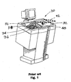
- FIG. 1 is a very diagrammatic view in perspective of a prior art Automatic Endoscope Reprocessor useful in the practice of the present invention.
- FIG. 2 is a plan view of a prior art rack with an endoscope therein suitable for use with the apparatus of FIG. 1 .
- Figure 3 is simplified diagrammatic view of a certain prior art type of endoscope suitable for reprocessing in the practice of the present invention.
- Figure 4 is a simplified diagrammatic view of another prior art type of endoscope suitable for reprocessing in the practice of the present invention.
- Figure 5 is a very simplified set of connection paths between the reprocessor and various channel configurations to illustrate various applications of the present invention.
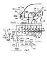
- Figure 6 is a simplified schematic flow path with a particular endoscope connected to a reprocessor in one embodiment of the present invention.
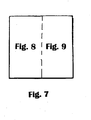
- Figure 7 is a key for Figures 8 and 9 .
- Figure 8 is a first portion of an example hydraulic schematic for a reprocessor useful in the practice of the present invention.
- Figure 9 is a second portion of the schematic of Figure 8 .
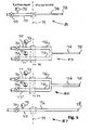
- Figure 10 is a pressure versus time waveform illustrating certain aspects of the present invention.
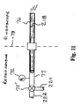
- Figure 11 is simplified schematic flow path illustrating application of an alternative embodiment of the present invention to a non-interconnected large channel.
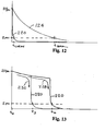
- Figure 12 is a pressure versus time waveform illustrating pressure decay characteristics of large and small channels in connection with the practice of the present invention.
- Figure 13 is a pressure versus time waveform illustrating further aspects of the alternative embodiment of the present invention.
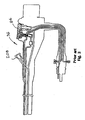
- Figure 14 is a section view of a full shutoff channel connector useful in the practice of the present invention, shown in an open position and connected to an endoscope fitting.
- Figure 15 is a section view of the channel connector of Figure 14 , shown in a disconnected and closed position.
- Figure 16 is an exterior perspective view of the channel connector shown in Figures 14 and 15 .
- a disinfecting device or Automatic Endoscope Reprocessor (or AER) 30 may be seen.
- the disinfecting device 30 is provided with two trays or basins 31 and 32 in which a rack 34 is, with an endoscope 36 therein, can be accommodated.
- a rack of this nature is located in the left hand tray.
- Each of trays 31 and 32 are provided with a counter-connection block which, when a rack 34 is placed in the tray 31 or 32, can be connected to the connection block 38 arranged in rack 34.
- the counter-connection block arranged in the right hand tray or basin 31 can be seen in Figure 1 and is denoted by the reference numeral 40.
- a lid 92 is shown in a partially open condition over right basin 32.
- the rack 34 may be formed from bent rods 42 and 44 which are fixedly connected to one another.
- the rack 34 is provided with one or two handles 46, by means of which the rack can be gripped and lifted up.
- the rack 34 is furthermore formed in such a manner that an endoscope 36 can be placed therein in a more or less folded state.
- the rack may be provided with a tip holder 50.
- One example of a connection made between the reprocessor 30 and the endoscope 36 is illustrated by a biopsy channel connector 82.
- connection block 38 is arranged fixedly in the rack. This connection block is provided with passages and ports 52 which can be connected to the passages of the endoscope 36 by means of flexible tubes 54. On its underside (not visible in Figure. 2 ), the connection block 38 is provided with connection points for the connection of the counter-connection block in either basin 31 or 32 of device 30.
- the connection block 38 is furthermore provided with a handle 56. By moving the handle 56, the connection block 38 can be connected to a counter-connection block or removed therefrom.
- Endoscope 36 is a first type of endoscope and endoscope 36' is a second type of endoscope differing from the first type of endoscope 36 in that it is provided with an additional channel 58 with connection 60 and an additional channel 62 with connection 64.
- the channel 62 is connected to an air channel 68 at a joining part 25.
- a biopsy channel fitting 208 may be seen in Figures 3 and 4 to which the connector 82 is attached in Figure 2 .
- FIG. 5 very simplified views of channel configurations to be tested for connectivity may be seen. These include: a. configuration 81, an independent small channel 74, b. configuration 83 which shows an interconnected pathway with one or more large channels 76 and a small channel 74, c. configuration 85 of an interconnected pathway with (only) three large channels 76, and d. a pathway or configuration 87 with only an independent large channel 76. It is to be understood that in configurations 81 and 83, the small channel 74 in the endoscope has a distal end 78 open to atmosphere, and in configurations 85 and 87 the large channel 76 in the endoscope has a distal end 75 open to atmosphere.
- the dashed line 79 indicates the interface between the reprocessor 30 and the endoscope 36 under test and includes the connection made between the connection block 38 and the counter connection block 40 (see Figure 1 ), along with respective flexible tubes 54 (see Figure 2 ).
- one or more valves 70 which may be understood to correspond to valves 96 in Figure 6 , described infra
- one or more pressure sensors 72 which may be understood to correspond to switches 98 in Figure 6 , described infra
- Pressure sensors 72 preferably have an adjustable trip point preset to a predetermined pressure level, for example 2 psi.
- the feed line 77 it has been found preferable to have the feed line 77 be 3 mm in diameter when the diameter of the small channel is about 0.5 mm.
- connectivity may be determined according to the first embodiment of the present invention wherein a pressurized gaseous fluid is delivered to the endoscope and the time of decay of pressure is monitored to determine the connectivity conditions of connected and open or disconnected.
- configuration 83 or 85 it is also possible to measure connectivity in a second embodiment by filling all channels with liquid under pressure (using, for example, a pump supplying water continuously through feed line 77) and measuring back pressure in the other reprocessor channel 77' (with the valve 70 in line 77' closed) to determine whether the endoscope is connected or not. If back pressure exceeds a predetermined level, both reprocessor channels 77 and 77' are connected to the endoscope channels 76.
- configurations 85 and 87 it is also possible to measure connectivity using a liquid (preferably water) "slug" to test the channels, whether they are large interconnected channels (as in configuration 85) or a non-interconnected large channel (as in configuration 87).
- a liquid preferably water
- Endoscope 36" has a control head 80 including a biopsy fitting on which is received the connector 82.
- Endoscope 36" also has a channel separator 84 installed, the details of which may be seen in Figures 3 and 4 .
- Endoscope 36" also has a light head 86 with a water connector 88, a suction connector 90, a jet connector 93, and an air connector 94.
- This embodiment of the present inventions uses a conventional connection block 38 to connect to the endoscope 36."
- the AER there are respective valves 96 (corresponding to valves 70 in Figure 5 ) and pressure switches 98 (corresponding to pressure sensors 72 in Figure 5 ).
- One valve 96 and switch 98 are associated (respectively) with each port 52 and line 54 that may be connected to the endoscope 36.” It is to be understood that more or fewer connections than those shown may be used in the practice of the present invention, depending on the complexity of the endoscope to be reprocessed.
- an air pump 101 provides air at line 102.
- Air pump 101 may be a double action reciprocating pump. Alternatively, air may be supplied as system air from a source of pressurized air in the facility in which the AER is installed. Pressurized air at line 102 may be passed through a regulator 104 which may be used to maintain an operating air pressure, which in the embodiment shown is 1.7 bar.
- a CYLINDER FILL valve 106 may be selectively operated to charge an air cylinder 108, which, in one embodiment may have a capacity of 0.89 liters.
- An air cylinder pressure switch 110 may be used to confirm that the air pressure in the cylinder is above a predetermined pressure, preferably 1.4 bar.
- An air filter 112 and a CHANNEL CONNECT VALVE 114 may be used to complete the connectivity system components in system 100. Valve 114 may connect either water from a channel pump 116 or air from the air cylinder 108, under the system control (not shown).
- a channel to be tested for connectivity is first purged of liquid, if necessary, and then the channel connect valve 114 is closed, and the air cylinder 108 is charged to a predetermined volume and pressure, after which the channel connect valve 114 is opened to admit air from the cylinder 108, it being understood that the endoscope is in place in the rack 34 in the AER 30 with the connection block 38 in fluid communication with the counter connection block 40.
- One of valves 96 is opened (either at the same time or after valve 114 is opened) and the time to discharge the particular channel in the endoscope 36" is monitored by the pressure switch 98 associated with and in fluid communication with the valve 96 that is opened.
- the time to reach that level is recorded by the control, and a determination is made whether that channel of the endoscope 36" is connected to its respective port 52 or whether the channel is disconnected from its port 52.
- a predetermined level for example, 2 psi
- the characteristic time to discharge for each channel is measured and stored in the control of the AER 30. If the time to actually discharge through the channel is shorter than the characteristic time for that channel, the endoscope is disconnected and an error signal indicating CHANNEL DISCONNECTED is given to the operator. If the actual time to discharge through the channel is equal to the characteristic time for that channel (within empirically determined tolerances) the AER 30 determines that the channel is connected and open.
- configuration 83 may also be tested using the above described embodiment in which case each of feed lines 77 and 77' may be tested independently by shutting off one and testing the other, or by monitoring both pressure sensors 72 while supplying gaseous fluid to one line (e.g., line 77), while the other (77' in this example) has its respective inlet valve 70 shut off. If both pressure sensors 72 reach the predetermined trip point pressure at about the characteristic time for this configuration, both channels are connected and open. If the time to reach the predetermined trip point pressure is less than the characteristic time, one or both channels are disconnected and an appropriate indication is given to the operator to check both channels 76 for connection to the reprocessor.
- Figure 7 is a key to illustrate the arrangement of Figures 8 and 9 .
- Figure 8 is a schematic or circuit 130 for the left basin 31
- Figure 9 is a schematic or circuit 132 for the right basin 32.
- Lid 92 is shown schematically in Figure 9 . It is to be understood that both a soap reservoir 134 and a pair of disinfectant reservoirs 136 are shared by each circuit 130 and 132. Circuits 130 and 132 also use a shared soap supply line 138. Circuits 130 and 132 share a pair of disinfectant supply lines 142 and 143.
- circuits 130 and 132 are joined at and share the following connections: a water source line 146, a compressed air source line 148, a lower pressure air line 150, preferably supplying air at 0.25 bar, for example, and a higher pressure air line 152 preferably supplying air at 2.0 to 2.4 bar, for example. Circuits 130 and 132 may also share a common drain connection line 154 and a common alcohol supply line 145. It is to be understood that the apparatus shown in Figures 8 and 9 is preferably contained within the enclosure of device 30 shown in Figure 1 .
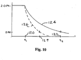
- FIG 10 illustrates more detail about the first embodiment of the present invention in which the system 100 of Figure 6 is used.
- Valve 114 is opened to air from cylinder 108 at a pressure of 20 psi at time t 1 120 and the incremental time from t 1 120 to t 2 122 is measured, by monitoring the appropriate switch 98, set to trip at 2 psi.
- the solid line curve 124 illustrates the pressure decay for a connected and open (unblocked) channel, while dashed line 126 represents a disconnected channel, with switch 98 activating at time 127.
- a characteristic curve 220 for a large channel pressure decay may be seen in comparison to a corresponding characteristic curve for a small channel pressure decay, e.g., curve 124.
- curve 220 can be taken to represent both connected and disconnected conditions for a large independent channel, because large channels characteristically have low flow restriction and little difference between connected and disconnected conditions and thus do not have enough separation between connected and disconnected conditions to allow the technique of using a flow restriction threshold to be reliable.
- one approach can be to provide connectors which shut off fluid flow when disconnected.
- a connector with full shutoff when the endoscope channel is disconnected allows a reversal of the logic conditions on whether disconnected or connected conditions restrict flow more. That is (for example) with a full shutoff connector, when the large channel is connected, there is no or little restriction to flow, but when the large channel is disconnected, the full shutoff connector will block flow, allowing detection of the disconnected condition for the large channel.
- shutoff connector 200 useful in the practice of one embodiment of the present invention is shown in Figures 14, 15 and 16 .
- the connector 200 has a barbed hose cap 202 threaded on a body 204 which carries a seal and retainer member 206 (similar or identical to the biopsy connector 82 shown in Figure 2 received over the biopsy channel fitting 208, shown in Figures 3 and 4 and as an example endoscope fitting in Figure 14 ) formed of a resilient material that may be placed over a fitting 208 on an endoscope 36.
- a spring 210 urges a seal 212 against a seat 211 in the body 204, blocking flow with respect to the cap 202 and any hose or tubing connected thereto, which is understood to be connected to the reprocessor 30 in operation.
- endoscope fitting 208 urges plunger 214 against spring 210, lifting seal 212 from seat 211 and opening the fluid flow path through the connector 200.
- Full shutoff connector 200 is useful with the configuration 87 for non-interconnected large channels. With that configuration, connector 200 has cap 202 connected to the connection block 38 via a flexible tube 54 and retainer member 206 is to be received over and sealed to an endoscope fitting 208.
- a connected and open condition will be indicated by a rapid decay response of curve 220 as indicated in Figure 12
- a disconnected condition will be indicated by no decay or a relatively slow decay as indicated by curve 226 in Figure 13 .
- Using the connector 200 in the configuration 87 with the second embodiment of pumping water or another liquid into the channel 76 and measuring back pressure can be accomplished by charging the channel 76 with liquid, then closing valve 70 and monitoring for pressure decay. If there is a decay, the channel is connected and open; if there is no decay, the channel is either disconnected or blocked, and must be corrected before continuing reprocessing the endoscope.
- another pressure switch or sensor may be used on feed line 77 to monitor a stalled head condition for the pump which results in a higher than operating pressure condition. With this approach, normal operating pressure sensed as back pressure indicates a connected and open channel; higher than normal operating pressure indicates that the pump is driving into a closed channel, indicating disconnection or blockage.
- feed line 77 may be connected to a source of liquid, preferably water, through conduit 222 to fill the reprocessor feed line 77 and the endoscope large channel 76 to which it is connected (or supposed to be connected) with a liquid slug 218 after which air is delivered via conduit 224 via a directional valve 70' through feed line 77 to large channel 76.
- the characteristic curves will now appear as in Figure 13 , with sequence 228 representing a connected condition and sequence 230 representing a disconnected condition.
- the water will discharge according to sequence 230 and follow curve 220 at time t 3 , with the time from to to t 3 representing the time to clear the water (or other liquid) slug 218 out from the feed line 77 (see e.g., configuration 87 in Figure 5 ). If the channel 76 is connected, the water slug will be discharged from distal end 75 at time t 4 , later than time t 3 .
- the incremental times between times t 0 , t 3 , t 4 and t 5 can be considered delay times and allow discrimination between the disconnected and connected conditions because of the differences in the mass of water propelled by the air pressure and length of channel through which the water is moved between disconnected and connected conditions.
- Time t 4 represents the time of a switch closure on switch 98 (corresponding to pressure sensor 72 in Figure 11 ) for a connected large channel 76.
- time t 3 will be monitored and recorded by the control system, indicating a disconnection between the reprocessor 30 and the endoscope 36 at this channel.
- this method may be used with large interconnected channels as in configuration 85, in addition to being useful in the large non-interconnected channel configuration 87.
- liquid is either already present in the feed lines 77 and 77' or is purposely supplied, and is supplied to fill channels 76 out to the distal end 75.
- feed line 77 is opened to admit air using an arrangement similar to that of conduits 222 and 224 and directional valve 70' as shown in Figure 11 .
- Sensors 72 monitor the time for back pressure to drop to the predetermined level (e.g., 2 psi) and the system can discriminate between a disconnected condition (when sequence 230 occurs with curve 220 sensed at time t 3 ), or a connected and open condition (when sequence 228 occurs and curve 220 is sensed at time t 4 ).
Description
- This invention relates to the field of reprocessors for devices, particularly medical devices, and more particularly to endoscopes and the like having one or more internal passageways which are to be cleaned and disinfected by an automatic reprocessor. Reprocessing includes washing, disinfecting and drying such devices. As used herein, the terms "endoscope" and "endoscopes" refer not only to endoscopes, but also to similar devices (including accessories) which may suitably be reprocessed using an Automatic Endoscope Reprocessor, or AER.
- In the past, AERs typically relied upon the human operator to properly connect and inspect the connections between the endoscope and the AER
- In the prior art, it was known to pressurize the sheath of an endoscope to test for leaks. In that type of test, if any leakage was measured, the endoscope under test was required to be serviced, since such testing was directed to a closed system in which it was expected and desired to have no leakage. However, with the present invention, testing for connectivity of channels in the endoscope must take leakage into account, since the distal end of the endoscope characteristically has one or more channel openings which will inherently (and properly) leak when the channel or channels are subjected to pressurized fluid. As such, conventional leak testing techniques of the prior art are not suitable for connectivity testing according to the present invention.
- Endoscopes which are candidates for the present invention include various configurations for through passages or channels, small non-interconnected channels, large non-interconnected channels, interconnected passages having at least one small channel, and interconnected passages having only large channels.
EP 0 709 056 A1 discloses a method and apparatus for cleaning and disinfecting endoscopes. The method comprises a leak test in which a pressure of 0.24 bar is conveyed to the space between the endoscope casing and the channels. If the pressure in this space falls from 0.24 bar to 0.14 bar in a period of 180 seconds, a leak is established in one of the channels and/or the outer casing.
EP 1 338 237
US 2005/0065405 A1 discloses an endoscope cleaning and disinfecting device for detecting clogging states of endoscope channels. The apparatus comprises a fluid supplying unit that supplies fluid to endoscope channels, a measuring unit that measures the pressure or the flow rate of the fluid flowing through the endoscope channels and a detecting unit that performs a comparison calculated based on measured values obtained by the measurement and set values so as to detect clogging states of the endoscope channels. If the flow rate exceeds an upper limit of the set range of flow rates, a determination is made that cleaning tubes are disconnected, channels in the cleaning and disinfection device are disconnected or a leakage occurs.
A further system for reprocessing and sterilizing endoscopes is known fromUS 6,068,815 . The reprocessing system includes a leak detection feature allowing for pressurizing the endoscope jacket within known air pressure and monitoring the air pressure loss by use of a pressure sensor.
FromDE 103 21 991 a system for checking the cleaning results of medical tubes of catheters connected with the water channel via a coupling is known. Upstream of the coupling a mechanical pressure sensor is provided. If the tube or catheter should be clogged, the pressure in the pressure sensor exceeds a certain threshold, in which a piston provided in the pressure sensor is shifted and the pressure is relieved. The shift of the piston is permanent even after the pressure has decreased, such that the mechanical pressure sensor acquires a memory effect. The coupling may be provided with a shut-off connector blocking fluid in the disconnected state. - The present invention surmounts shortcomings of the prior art by providing apparatus and method to automatically and efficiently detect whether a proper connection exits between the reprocessor and the endoscope or whether there are any missing connections (i.e., disconnection) between a specific channel in the endoscope and the AER. In particular, the invention surmounts the shortcomings of the prior art by providing a method as defined in
claim 1,claim 10 and claim 11. - In one aspect, the present invention utilizes a tank which may be pressurized with a suitable fluid (which may be a gas such as air in one or more embodiments), and discharged through an endoscope being reprocessed with a characteristic time to discharge monitored. Herein, a charge or "slug" of liquid is either already present in or delivered to the endoscope and is thereafter combined with the gaseous fluid and discharged through an endoscope being reprocessed, with a characteristic time to discharge monitored. With either embodiment, the present invention determines whether the path or channel is disconnected or connected and open.
- In another aspect, the fluid is used to detect connectivity and a pump may be used to deliver the fluid to respective paths in the endoscope, with the time monitored to determine when (and if) the pressure drops to a predetermined pressure level, and if the pressure does so drop, a comparison is made to characteristic times corresponding to the conditions in which the path or channel is disconnected or connected and open.
- In still another aspect, a full shutoff connector may be used with large channels to "reverse" the logic for determining whether the large channel is disconnected, or connected to the reprocessor and open.
-
FIG. 1 is a very diagrammatic view in perspective of a prior art Automatic Endoscope Reprocessor useful in the practice of the present invention. -
FIG. 2 is a plan view of a prior art rack with an endoscope therein suitable for use with the apparatus ofFIG. 1 . -
Figure 3 is simplified diagrammatic view of a certain prior art type of endoscope suitable for reprocessing in the practice of the present invention. -
Figure 4 is a simplified diagrammatic view of another prior art type of endoscope suitable for reprocessing in the practice of the present invention. -
Figure 5 is a very simplified set of connection paths between the reprocessor and various channel configurations to illustrate various applications of the present invention. -
Figure 6 is a simplified schematic flow path with a particular endoscope connected to a reprocessor in one embodiment of the present invention. -
Figure 7 is a key forFigures 8 and9 . -
Figure 8 is a first portion of an example hydraulic schematic for a reprocessor useful in the practice of the present invention. -
Figure 9 is a second portion of the schematic ofFigure 8 . -
Figure 10 is a pressure versus time waveform illustrating certain aspects of the present invention. -
Figure 11 is simplified schematic flow path illustrating application of an alternative embodiment of the present invention to a non-interconnected large channel. -
Figure 12 is a pressure versus time waveform illustrating pressure decay characteristics of large and small channels in connection with the practice of the present invention. -
Figure 13 is a pressure versus time waveform illustrating further aspects of the alternative embodiment of the present invention. -
Figure 14 is a section view of a full shutoff channel connector useful in the practice of the present invention, shown in an open position and connected to an endoscope fitting. -
Figure 15 is a section view of the channel connector ofFigure 14 , shown in a disconnected and closed position. -
Figure 16 is an exterior perspective view of the channel connector shown inFigures 14 and 15 . - One example of a system for cleaning, disinfecting and/or drying endoscopes is shown in United States Patent
6,641,781 B2, issued November 4, 2003 . - Another example of a device and method for cleaning and/or disinfecting endoscopes is shown in United States Patent
6,260,560 B1, issued July 17, 2001 . - Still another example of a device and metho for cleaning and/or disinfecting endoscopes is shown in the afore-mentioned European Patent Application
EP 0 709 056 A1, published 01.05.1996 ). - Referring now most particularly to
Figure 1 , a disinfecting device or Automatic Endoscope Reprocessor (or AER) 30 may be seen. The disinfectingdevice 30 is provided with two trays orbasins rack 34 is, with anendoscope 36 therein, can be accommodated. InFigure 1 , a rack of this nature is located in the left hand tray. Each oftrays rack 34 is placed in thetray connection block 38 arranged inrack 34. The counter-connection block arranged in the right hand tray orbasin 31 can be seen inFigure 1 and is denoted by thereference numeral 40. Alid 92 is shown in a partially open condition overright basin 32. - Referring now also to
Figure 2 , therack 34 may be formed frombent rods rack 34 is provided with one or twohandles 46, by means of which the rack can be gripped and lifted up. Therack 34 is furthermore formed in such a manner that anendoscope 36 can be placed therein in a more or less folded state. In order to be able to fix in particular thefragile end 48 of the endoscope, the rack may be provided with atip holder 50. One example of a connection made between the reprocessor 30 and theendoscope 36 is illustrated by abiopsy channel connector 82. - The
connection block 38 is arranged fixedly in the rack. This connection block is provided with passages andports 52 which can be connected to the passages of theendoscope 36 by means offlexible tubes 54. On its underside (not visible inFigure. 2 ), theconnection block 38 is provided with connection points for the connection of the counter-connection block in eitherbasin device 30. Theconnection block 38 is furthermore provided with ahandle 56. By moving thehandle 56, theconnection block 38 can be connected to a counter-connection block or removed therefrom. - Referring now to
Figures 3 and4 , examples of different types ofendoscopes 36, 36' to be reprocessed by thedevice 30 may be seen.Endoscope 36 is a first type of endoscope and endoscope 36' is a second type of endoscope differing from the first type ofendoscope 36 in that it is provided with anadditional channel 58 withconnection 60 and anadditional channel 62 withconnection 64. In ahead part 66, thechannel 62 is connected to anair channel 68 at a joiningpart 25. A biopsy channel fitting 208 may be seen inFigures 3 and4 to which theconnector 82 is attached inFigure 2 . - Referring to
Figure 5 , very simplified views of channel configurations to be tested for connectivity may be seen. These include: a.configuration 81, an independentsmall channel 74, b.configuration 83 which shows an interconnected pathway with one or morelarge channels 76 and asmall channel 74,c. configuration 85 of an interconnected pathway with (only) threelarge channels 76, and d. a pathway orconfiguration 87 with only an independentlarge channel 76. It is to be understood that inconfigurations small channel 74 in the endoscope has adistal end 78 open to atmosphere, and inconfigurations large channel 76 in the endoscope has adistal end 75 open to atmosphere. The dashedline 79 indicates the interface between the reprocessor 30 and theendoscope 36 under test and includes the connection made between theconnection block 38 and the counter connection block 40 (seeFigure 1 ), along with respective flexible tubes 54 (seeFigure 2 ). In each of these arrangements, one or more valves 70 (which may be understood to correspond tovalves 96 inFigure 6 , described infra) and one or more pressure sensors 72 (which may be understood to correspond toswitches 98 inFigure 6 , described infra) are provided in the reprocessor side.Pressure sensors 72 preferably have an adjustable trip point preset to a predetermined pressure level, for example 2 psi. In the top diagram (configuration 81) inFigure 5 , it has been found preferable to have thefeed line 77 be 3 mm in diameter when the diameter of the small channel is about 0.5 mm. - In
configuration - In
configuration valve 70 in line 77' closed) to determine whether the endoscope is connected or not. If back pressure exceeds a predetermined level, bothreprocessor channels 77 and 77' are connected to theendoscope channels 76. If pressure is applied inchannel 77 and back pressure is absent in channel 77' (as indicated bypressure sensor 72 connected to channel 77') the system will determine that a blockage exists in one or both ofchannels 77 and 77' or thatchannel 77 or channel 77' (or both) are disconnected, each of which conditions require that reprocessing be interrupted and the condition appropriately corrected. - In
configurations - Finally, with
configuration 87 it is also possible to use a full shutoff connector (described infra with respect toFigures 14-16 ) in an alternative embodiment of the present invention. - Referring now to
Figure 6 , a less simplified schematic showing connections to a specific model ofendoscope 36" (similar toendoscopes 36 and 36') for carrying out the present invention in one embodiment may be seen.Endoscope 36" has acontrol head 80 including a biopsy fitting on which is received theconnector 82.Endoscope 36" also has achannel separator 84 installed, the details of which may be seen inFigures 3 and4 .Endoscope 36" also has alight head 86 with awater connector 88, asuction connector 90, ajet connector 93, and anair connector 94. This embodiment of the present inventions uses aconventional connection block 38 to connect to theendoscope 36." In the AER there are respective valves 96 (corresponding tovalves 70 inFigure 5 ) and pressure switches 98 (corresponding to pressuresensors 72 inFigure 5 ). Onevalve 96 and switch 98 are associated (respectively) with eachport 52 andline 54 that may be connected to theendoscope 36." It is to be understood that more or fewer connections than those shown may be used in the practice of the present invention, depending on the complexity of the endoscope to be reprocessed. - In the embodiment shown in
Figure 6 , the parts included within dashed line 100 have been added to carry out the first embodiment of the present invention. In the first embodiment, anair pump 101 provides air atline 102.Air pump 101 may be a double action reciprocating pump. Alternatively, air may be supplied as system air from a source of pressurized air in the facility in which the AER is installed. Pressurized air atline 102 may be passed through aregulator 104 which may be used to maintain an operating air pressure, which in the embodiment shown is 1.7 bar. ACYLINDER FILL valve 106 may be selectively operated to charge anair cylinder 108, which, in one embodiment may have a capacity of 0.89 liters. An aircylinder pressure switch 110 may be used to confirm that the air pressure in the cylinder is above a predetermined pressure, preferably 1.4 bar. Anair filter 112 and a CHANNEL CONNECT VALVE 114 may be used to complete the connectivity system components in system 100. Valve 114 may connect either water from achannel pump 116 or air from theair cylinder 108, under the system control (not shown). - In operation with the first embodiment using a gaseous fluid such as air, a channel to be tested for connectivity is first purged of liquid, if necessary, and then the channel connect valve 114 is closed, and the
air cylinder 108 is charged to a predetermined volume and pressure, after which the channel connect valve 114 is opened to admit air from thecylinder 108, it being understood that the endoscope is in place in therack 34 in theAER 30 with theconnection block 38 in fluid communication with thecounter connection block 40. One ofvalves 96 is opened (either at the same time or after valve 114 is opened) and the time to discharge the particular channel in theendoscope 36" is monitored by thepressure switch 98 associated with and in fluid communication with thevalve 96 that is opened. When the pressure drops to a predetermined level, for example, 2 psi, the time to reach that level is recorded by the control, and a determination is made whether that channel of theendoscope 36" is connected to itsrespective port 52 or whether the channel is disconnected from itsport 52. It is to be understood that the characteristic time to discharge for each channel is measured and stored in the control of theAER 30. If the time to actually discharge through the channel is shorter than the characteristic time for that channel, the endoscope is disconnected and an error signal indicating CHANNEL DISCONNECTED is given to the operator. If the actual time to discharge through the channel is equal to the characteristic time for that channel (within empirically determined tolerances) theAER 30 determines that the channel is connected and open. - It is to be understood that in addition to
configuration 81,configuration 83 may also be tested using the above described embodiment in which case each offeed lines 77 and 77' may be tested independently by shutting off one and testing the other, or by monitoring bothpressure sensors 72 while supplying gaseous fluid to one line (e.g., line 77), while the other (77' in this example) has itsrespective inlet valve 70 shut off. If bothpressure sensors 72 reach the predetermined trip point pressure at about the characteristic time for this configuration, both channels are connected and open. If the time to reach the predetermined trip point pressure is less than the characteristic time, one or both channels are disconnected and an appropriate indication is given to the operator to check bothchannels 76 for connection to the reprocessor. - Referring now to
Figures 7 ,8 and9 , a hydraulic schematic for the practice of the present invention may be seen.Figure 7 is a key to illustrate the arrangement ofFigures 8 and9 .Figure 8 is a schematic orcircuit 130 for theleft basin 31, andFigure 9 is a schematic orcircuit 132 for theright basin 32.Lid 92 is shown schematically inFigure 9 . It is to be understood that both asoap reservoir 134 and a pair ofdisinfectant reservoirs 136 are shared by eachcircuit Circuits soap supply line 138.Circuits disinfectant supply lines circuits water source line 146, a compressedair source line 148, a lower pressure air line 150, preferably supplying air at 0.25 bar, for example, and a higher pressure air line 152 preferably supplying air at 2.0 to 2.4 bar, for example.Circuits drain connection line 154 and a commonalcohol supply line 145. It is to be understood that the apparatus shown inFigures 8 and9 is preferably contained within the enclosure ofdevice 30 shown inFigure 1 . -
Figure 10 illustrates more detail about the first embodiment of the present invention in which the system 100 ofFigure 6 is used. Valve 114 is opened to air fromcylinder 108 at a pressure of 20 psi at time t1 120 and the incremental time from t1 120 to t2 122 is measured, by monitoring theappropriate switch 98, set to trip at 2 psi. The actual time (tactual = t2 - t1) is compared to the previously recorded characteristic time tCHAR to determine the connectivity condition of the channel under test. Thesolid line curve 124 illustrates the pressure decay for a connected and open (unblocked) channel, while dashed line 126 represents a disconnected channel, withswitch 98 activating attime 127. - The above described operation will be satisfactory with most small channels because there is a considerable difference between the connected and disconnected conditions. In addition some connectors used for certain small channels (for example the Lift channels and some Jet channels) have additional restriction which tends to decrease the separation between disconnected and connected conditions.
- Referring now also to
Figure 12 , acharacteristic curve 220 for a large channel pressure decay may be seen in comparison to a corresponding characteristic curve for a small channel pressure decay, e.g.,curve 124. It is to be understood thatcurve 220 can be taken to represent both connected and disconnected conditions for a large independent channel, because large channels characteristically have low flow restriction and little difference between connected and disconnected conditions and thus do not have enough separation between connected and disconnected conditions to allow the technique of using a flow restriction threshold to be reliable. However, since there are only a small number of types of connectors required to connect to large channels, one approach can be to provide connectors which shut off fluid flow when disconnected. In this type of connector, flow is shut off when the channel is disconnected, and full, generally unrestricted, flow is permitted or enabled when the connector is coupled together, and the channel is connected to the AER. A connector with full shutoff when the endoscope channel is disconnected allows a reversal of the logic conditions on whether disconnected or connected conditions restrict flow more. That is (for example) with a full shutoff connector, when the large channel is connected, there is no or little restriction to flow, but when the large channel is disconnected, the full shutoff connector will block flow, allowing detection of the disconnected condition for the large channel. - One manufacturer of shutoff connectors is the Colder Products Company, of 1001 Westgate Drive, St. Paul, Minnesota 55114, which offers a PMC12 series of shutoff connectors. Another
full shutoff connector 200 useful in the practice of one embodiment of the present invention is shown inFigures 14, 15 and16 . Theconnector 200 has abarbed hose cap 202 threaded on abody 204 which carries a seal and retainer member 206 (similar or identical to thebiopsy connector 82 shown inFigure 2 received over the biopsy channel fitting 208, shown inFigures 3 and4 and as an example endoscope fitting inFigure 14 ) formed of a resilient material that may be placed over a fitting 208 on anendoscope 36. When theconnector 200 is disconnected from theendoscope 36, aspring 210 urges aseal 212 against aseat 211 in thebody 204, blocking flow with respect to thecap 202 and any hose or tubing connected thereto, which is understood to be connected to the reprocessor 30 in operation. When theconnector 200 is connected to theendoscope 36, endoscope fitting 208 urgesplunger 214 againstspring 210, liftingseal 212 fromseat 211 and opening the fluid flow path through theconnector 200. -
Full shutoff connector 200 is useful with theconfiguration 87 for non-interconnected large channels. With that configuration,connector 200 hascap 202 connected to theconnection block 38 via aflexible tube 54 andretainer member 206 is to be received over and sealed to anendoscope fitting 208. - Using the
connector 200 in theconfiguration 87 with a non-interconnected large channel, and practicing the present invention according to the first embodiment wherein a gaseous fluid is delivered viafeed line 77, a connected and open condition will be indicated by a rapid decay response ofcurve 220 as indicated inFigure 12 , while a disconnected condition will be indicated by no decay or a relatively slow decay as indicated by curve 226 inFigure 13 . - Using the
connector 200 in theconfiguration 87 with the second embodiment of pumping water or another liquid into thechannel 76 and measuring back pressure can be accomplished by charging thechannel 76 with liquid, then closingvalve 70 and monitoring for pressure decay. If there is a decay, the channel is connected and open; if there is no decay, the channel is either disconnected or blocked, and must be corrected before continuing reprocessing the endoscope. Alternatively, another pressure switch or sensor may be used onfeed line 77 to monitor a stalled head condition for the pump which results in a higher than operating pressure condition. With this approach, normal operating pressure sensed as back pressure indicates a connected and open channel; higher than normal operating pressure indicates that the pump is driving into a closed channel, indicating disconnection or blockage. - The alternative embodiment of the present invention mentioned above which uses a liquid (preferably water) "slug" or charge in the channel under test in connection with the gaseous fluid decay sensor system is described here in more detail. This embodiment is useful with the
large channel configurations - Referring now to
Figure 11 ,feed line 77 may be connected to a source of liquid, preferably water, through conduit 222 to fill thereprocessor feed line 77 and the endoscopelarge channel 76 to which it is connected (or supposed to be connected) with aliquid slug 218 after which air is delivered via conduit 224 via a directional valve 70' throughfeed line 77 tolarge channel 76. The characteristic curves will now appear as inFigure 13 , with sequence 228 representing a connected condition andsequence 230 representing a disconnected condition. If thechannel 76 is disconnected from the reprocessor, the water will discharge according tosequence 230 and followcurve 220 at time t3, with the time from to to t3 representing the time to clear the water (or other liquid)slug 218 out from the feed line 77 (see e.g.,configuration 87 inFigure 5 ). If thechannel 76 is connected, the water slug will be discharged fromdistal end 75 at time t4, later than time t3. The incremental times between times t0, t3, t4 and t5 can be considered delay times and allow discrimination between the disconnected and connected conditions because of the differences in the mass of water propelled by the air pressure and length of channel through which the water is moved between disconnected and connected conditions. Time t4 represents the time of a switch closure on switch 98 (corresponding to pressuresensor 72 inFigure 11 ) for a connectedlarge channel 76. In the eventlarge channel 76 is disconnected, time t3 will be monitored and recorded by the control system, indicating a disconnection between the reprocessor 30 and theendoscope 36 at this channel. Similar to the operation with respect toconfiguration 83, this method may be used with large interconnected channels as inconfiguration 85, in addition to being useful in the largenon-interconnected channel configuration 87. Forconfiguration 85, liquid is either already present in thefeed lines 77 and 77' or is purposely supplied, and is supplied to fillchannels 76 out to thedistal end 75. Once the configuration is filled with liquid,feed line 77 is opened to admit air using an arrangement similar to that of conduits 222 and 224 and directional valve 70' as shown inFigure 11 .Sensors 72 monitor the time for back pressure to drop to the predetermined level (e.g., 2 psi) and the system can discriminate between a disconnected condition (whensequence 230 occurs withcurve 220 sensed at time t3), or a connected and open condition (when sequence 228 occurs andcurve 220 is sensed at time t4).
Claims (10)
- A method of detecting connectivity between an automatic reprocessor and a channel in an endoscope undergoing reprocessing using said automatic reprocessor, the method comprising:a. providing a source of pressurized gaseous fluid;a.1. supplying a liquid to a channel in an endoscope;b. directing the pressurized gaseous fluid to said channel;c. discontinuing pressurizing the fluid;d. monitoring the back pressure in the pressurized fluid; ande. determining whether the channel is connected and open or disconnected by monitoring the time after commencement of step c for actual back pressure to fall to a predetermined value corresponding to the specific channel and model of endoscope undergoing reprocessing.
- The method of claim 1 wherein the source of pressurized fluid is one of: a tank and a pump.
- The method of claim 1 wherein the liquid includes water.
- The method of claim 3 wherein step e further comprises determining the channel is disconnected when the time for the actual back pressure to fall to the predetermined value is less than a first predetermined time.
- The method of claim 4 wherein step e further comprises determining the channel is con- - nected and open when the time for the actual back pressure to fall to the predetermined value is greater than the first predetermined time.
- The method of claim 1, wherein:step d. comprises monitoring the decay of back pressure in the channel under test; andstep e. comprises determining whether the channel is connected and open or is disconnected by comparing the time for the pressure in the channel under test to decay to a predetermined level to one or more predetermined times corresponding to the specific channel and model of endoscope undergoing reprocessing.
- The method of claim 6 further comprising:f. providing an indication that the channel under test is disconnected if the time for the pressure in the channel under test to decay to a predetermined level is less than a first predetermined time.
- The method of claim 7 further comprising:g. providing an indication that the channel under test is connected and open if the time / for the pressure in the channel under test to decay to a predetermined level is greater than the first predetermined time and less than a second predetermined time.
- A method of determining whether a channel in an endoscope is connected to a reprocessor comprising the steps of:a. providing a shut off connector in a fluid path between a channel in the endoscope and a reprocessor wherein the shut off connectori. blocks fluid flow when the channel is disconnected from the reprocessor, andii. enables fluid flow when the channel is connected to the reprocessor;b. providing a source of pressurized gaseous fluid in the reprocessor directed to the fluid path;c. discontinuing pressurizing the fluid path in the reprocessor;d. monitoring the back pressure in the fluid path; ande. determining whether the channel is connected and open or disconnected by monitoring a characteristic of the pressure in the fluid path.
- The method of claim 9 wherein the characteristic of the pressure comprises one of:a level of the pressure in the fluid path;a time to decay to a predetermined level of pressure in the fluid path; anda delay time to a decay time for the pressure in the fluid path.
Priority Applications (1)
| Application Number | Priority Date | Filing Date | Title |
|---|---|---|---|
| EP13165561.5A EP2628440B1 (en) | 2005-11-02 | 2006-10-31 | Endoscope reprocessor connectivity method |
Applications Claiming Priority (2)
| Application Number | Priority Date | Filing Date | Title |
|---|---|---|---|
| US11/264,909 US7901349B2 (en) | 2005-11-02 | 2005-11-02 | Endoscope reprocessor connectivity apparatus and method |
| PCT/US2006/060389 WO2007089358A2 (en) | 2005-11-02 | 2006-10-31 | Endoscope reprocessor connectivity apparatus and method |
Related Child Applications (2)
| Application Number | Title | Priority Date | Filing Date |
|---|---|---|---|
| EP13165561.5A Division EP2628440B1 (en) | 2005-11-02 | 2006-10-31 | Endoscope reprocessor connectivity method |
| EP13165561.5 Division-Into | 2013-04-26 |
Publications (2)
| Publication Number | Publication Date |
|---|---|
| EP1942786A2 EP1942786A2 (en) | 2008-07-16 |
| EP1942786B1 true EP1942786B1 (en) | 2013-09-11 |
Family
ID=37997409
Family Applications (2)
| Application Number | Title | Priority Date | Filing Date |
|---|---|---|---|
| EP06850420.8A Active EP1942786B1 (en) | 2005-11-02 | 2006-10-31 | Endoscope reprocessor connectivity method |
| EP13165561.5A Active EP2628440B1 (en) | 2005-11-02 | 2006-10-31 | Endoscope reprocessor connectivity method |
Family Applications After (1)
| Application Number | Title | Priority Date | Filing Date |
|---|---|---|---|
| EP13165561.5A Active EP2628440B1 (en) | 2005-11-02 | 2006-10-31 | Endoscope reprocessor connectivity method |
Country Status (4)
| Country | Link |
|---|---|
| US (1) | US7901349B2 (en) |
| EP (2) | EP1942786B1 (en) |
| JP (2) | JP5416409B2 (en) |
| WO (1) | WO2007089358A2 (en) |
Families Citing this family (20)
| Publication number | Priority date | Publication date | Assignee | Title |
|---|---|---|---|---|
| US8109871B2 (en) | 2005-05-06 | 2012-02-07 | Minntech Corporation | Endoscope integrity tester including context-sensitive compensation and methods of context-sensitive integrity testing |
| JP5188800B2 (en) * | 2007-12-21 | 2013-04-24 | オリンパスメディカルシステムズ株式会社 | Endoscope cleaning / disinfecting apparatus and water leakage detection method using the endoscope cleaning / disinfecting apparatus |
| DE102008026445A1 (en) * | 2008-06-03 | 2009-12-10 | Olympus Winter & Ibe Gmbh | Method for testing the patency of an endoscope channel and endoscope washing machine therefor |
| US10478125B2 (en) | 2008-09-09 | 2019-11-19 | Pulmonx Corporation | Systems and methods for flushing an assessment catheter |
| US8673212B2 (en) * | 2010-05-28 | 2014-03-18 | Steris Corporation | Apparatus to decontaminate equipment containing internal channels |
| EP2594220B1 (en) * | 2011-11-15 | 2020-08-19 | Belimed AG | Connection device for a cleaning device for cleaning instruments with at least one lumen to be cleaned |
| DE102012020934B4 (en) * | 2012-10-25 | 2014-08-21 | SciCan GmbH | Method for cleaning and disinfecting endoscopes |
| DE102013205296A1 (en) * | 2013-03-26 | 2014-10-02 | Olympus Winter & Ibe Gmbh | Method and system for monitoring a reprocessing device for endoscopes |
| US9518013B2 (en) | 2014-12-18 | 2016-12-13 | Ecolab Usa Inc. | Generation of peroxyformic acid through polyhydric alcohol formate |
| US11040902B2 (en) | 2014-12-18 | 2021-06-22 | Ecolab Usa Inc. | Use of percarboxylic acids for scale prevention in treatment systems |
| EP3232781A4 (en) | 2014-12-18 | 2018-08-22 | Ecolab USA Inc. | Methods for forming peroxyformic acid and uses thereof |
| CN106793934B (en) * | 2015-08-24 | 2019-01-22 | 奥林巴斯株式会社 | Cleaning-sterlizing machine for endoscope |
| WO2017038132A1 (en) * | 2015-09-02 | 2017-03-09 | オリンパス株式会社 | Endoscope reprocessor |
| US10201269B2 (en) * | 2016-05-18 | 2019-02-12 | Ethicon, Inc. | Apparatus and method for reprocessing a medical device |
| US10772491B2 (en) * | 2016-07-22 | 2020-09-15 | Steris Inc. | Apparatus for decontaminating equipment having internal channels (lumens) |
| DE102016216403A1 (en) * | 2016-08-31 | 2018-03-01 | Olympus Winter & Ibe Gmbh | Preparation of surgical instruments, in particular endoscopes |
| WO2018195655A1 (en) | 2017-04-25 | 2018-11-01 | 9485562 Canada Inc. | Endoscope cleaning station having leak tester and high-pressure port |
| EP3797676B1 (en) * | 2018-05-07 | 2023-04-26 | Olympus Corporation | Endoscope reprocessor |
| AU2019285304B2 (en) | 2018-06-15 | 2021-10-14 | Ecolab Usa Inc. | On site generated performic acid compositions for teat treatment |
| WO2023181983A1 (en) * | 2022-03-22 | 2023-09-28 | 富士フイルム株式会社 | Endoscope conduit condition determination method, endoscope conduit condition determination device, and endoscope cleaning/disinfecting device |
Family Cites Families (34)
| Publication number | Priority date | Publication date | Assignee | Title |
|---|---|---|---|---|
| US5077008A (en) * | 1986-02-06 | 1991-12-31 | Steris Corporation | Anti-microbial composition |
| US5279799A (en) * | 1990-10-23 | 1994-01-18 | Hamo Ag | Apparatus for cleaning and testing endoscopes |
| JP3190446B2 (en) * | 1992-08-28 | 2001-07-23 | オリンパス光学工業株式会社 | Endoscope leak detection device |
| EP0603563A1 (en) * | 1992-12-04 | 1994-06-29 | F. Gehrig + Co. Ag | Method and apparatus for testing and cleaning endoscopes |
| US5367797A (en) * | 1993-10-25 | 1994-11-29 | Omega Environmental, Inc. | Process for testing a vessel |
| NL9401788A (en) | 1994-10-27 | 1996-06-03 | Fujinon Medical Holland B V | Method and device for cleaning and disinfecting endoscopes. |
| DE4440363C2 (en) * | 1994-11-11 | 1997-10-02 | Netzsch Newamatic Gmbh | Procedure for testing and cleaning instruments for minimally invasive surgery or minimally invasive examination of body cavities |
| US5761069A (en) * | 1995-11-09 | 1998-06-02 | Custom Ultrasonics, Inc. | Integrated system for cleaning medical instruments |
| JPH1019720A (en) * | 1996-06-27 | 1998-01-23 | Miura Co Ltd | Method and apparatus for detecting abnormality of hermetic device |
| NL1006053C2 (en) * | 1997-05-14 | 1998-11-19 | Johannes Antonius Walta | Device and method for cleaning and / or disinfecting endoscopes. |
| US6047431A (en) * | 1997-11-21 | 2000-04-11 | Olympus America Inc. | Methods and apparatus for cleaning channels |
| NL1010130C2 (en) * | 1998-09-18 | 2000-03-27 | Johannes Antonius Ir Walta | System for cleaning, disinfecting and / or drying endoscopes. |
| WO2000018521A1 (en) * | 1998-10-01 | 2000-04-06 | Minntech Corporation | Reverse flow cleaning and sterilizing device and method |
| US6203767B1 (en) * | 1998-11-06 | 2001-03-20 | Steris Corporation | Peracetic acid card reader and card style sensor |
| KR100583984B1 (en) * | 1999-02-03 | 2006-05-26 | 메디테크닉 인코퍼레이티드 | Device for sterilizing a chamber |
| US6412334B1 (en) * | 2000-02-07 | 2002-07-02 | Steris Inc. | Leak detector for endoscopes |
| US6408682B2 (en) * | 2000-02-07 | 2002-06-25 | Steris Inc. | Leak detection method for endoscopes |
| JP4633274B2 (en) * | 2000-02-17 | 2011-02-16 | オリンパス株式会社 | Endoscope cleaning and disinfection device |
| JP2002243572A (en) * | 2001-02-21 | 2002-08-28 | Osaka Gas Co Ltd | Method and device for inspecting piping leakage |
| JP3691764B2 (en) * | 2001-03-07 | 2005-09-07 | オリンパス株式会社 | Autoclave equipment |
| GB0130825D0 (en) | 2001-12-22 | 2002-02-06 | Labcaire Systems Ltd | Detector system |
| DE10208035B4 (en) | 2002-02-26 | 2005-10-06 | Bht Hygiene Technik Gmbh | Device for checking the continuity of endoscope channels |
| JP3820168B2 (en) * | 2002-03-15 | 2006-09-13 | オリンパス株式会社 | Leak tester |
| FR2837392B1 (en) * | 2002-03-20 | 2004-07-02 | Bernard Mariotti | METHOD AND DEVICE FOR MEASURING AND CONTROLLING THE FLOW CIRCULATION IN ENDOSCOPE CHANNELS |
| US20040118437A1 (en) * | 2002-12-23 | 2004-06-24 | Nguyen Nick Ngoc | Method of detecting flow in endoscope channels |
| US6986736B2 (en) * | 2002-12-23 | 2006-01-17 | Advanced Sterilization Products | Automated endoscope reprocessor connection integrity testing |
| US6848456B2 (en) * | 2003-01-13 | 2005-02-01 | Custom Ultrasonics, Inc. | Method for determining the existence of obstructions in the passageways of a medical instrument |
| US20040139789A1 (en) * | 2003-01-16 | 2004-07-22 | Master Endoscope Llc | Leak tester for an endoscope and associated method |
| DE10321991B3 (en) | 2003-05-16 | 2004-05-19 | Bht Hygiene Technik Gmbh | Cleaning and disinfection equipment with flow connectors for medical tubing and catheters, includes flow restrictions and pressure sensors with memory |
| US7276023B2 (en) * | 2004-08-25 | 2007-10-02 | Bht Hygienetechnik Gmbh | Device for checking endoscope channels |
| US20060224042A1 (en) * | 2005-03-31 | 2006-10-05 | Richard Jackson | Automated endoscope reprocessor connection integrity testing via liquid suction |
| US7340943B2 (en) * | 2005-09-30 | 2008-03-11 | Ethicon, Inc. | Method of detecting connection of test port on an endoscope |
| US7686761B2 (en) * | 2005-10-28 | 2010-03-30 | Ethicon, Inc. | Method of detecting proper connection of an endoscope to an endoscope processor |
| US7918788B2 (en) * | 2005-10-31 | 2011-04-05 | Ethicon, Inc. | Apparatus and method for providing flow to endoscope channels |
-
2005
- 2005-11-02 US US11/264,909 patent/US7901349B2/en active Active
-
2006
- 2006-10-31 WO PCT/US2006/060389 patent/WO2007089358A2/en active Application Filing
- 2006-10-31 EP EP06850420.8A patent/EP1942786B1/en active Active
- 2006-10-31 EP EP13165561.5A patent/EP2628440B1/en active Active
- 2006-10-31 JP JP2008539142A patent/JP5416409B2/en active Active
-
2013
- 2013-09-25 JP JP2013197938A patent/JP5667264B2/en active Active
Also Published As
| Publication number | Publication date |
|---|---|
| EP2628440B1 (en) | 2015-01-07 |
| WO2007089358A3 (en) | 2008-01-24 |
| JP5667264B2 (en) | 2015-02-12 |
| US20070100204A1 (en) | 2007-05-03 |
| EP2628440A1 (en) | 2013-08-21 |
| JP5416409B2 (en) | 2014-02-12 |
| WO2007089358A2 (en) | 2007-08-09 |
| JP2009514611A (en) | 2009-04-09 |
| EP1942786A2 (en) | 2008-07-16 |
| US7901349B2 (en) | 2011-03-08 |
| JP2014012225A (en) | 2014-01-23 |
Similar Documents
| Publication | Publication Date | Title |
|---|---|---|
| EP1942786B1 (en) | Endoscope reprocessor connectivity method | |
| EP1769721B1 (en) | Method of detecting integrity of test connection of endoscopes | |
| AU2006233273B2 (en) | Apparatus and method for providing flow to endoscope channels | |
| US20040118437A1 (en) | Method of detecting flow in endoscope channels | |
| AU2006201276A1 (en) | Automated endoscope reprocessor connection integrity testing via liquid suction | |
| US6915810B2 (en) | Apparatus for reprocessing a device having internal passageways | |
| US20070102044A1 (en) | Disinfectant transfer system | |
| US20070193604A1 (en) | Method for determining a fluid flow in a passageway of a medical device using pressure measurement | |
| CA2585722C (en) | Method for reprocessing a medical device with a plurality of internal passageways |
Legal Events
| Date | Code | Title | Description |
|---|---|---|---|
| PUAI | Public reference made under article 153(3) epc to a published international application that has entered the european phase |
Free format text: ORIGINAL CODE: 0009012 |
|
| 17P | Request for examination filed |
Effective date: 20080424 |
|
| AK | Designated contracting states |
Kind code of ref document: A2 Designated state(s): AT BE BG CH CY CZ DE DK EE ES FI FR GB GR HU IE IS IT LI LT LU LV MC NL PL PT RO SE SI SK TR |
|
| AX | Request for extension of the european patent |
Extension state: AL BA HR MK RS |
|
| 17Q | First examination report despatched |
Effective date: 20081202 |
|
| RBV | Designated contracting states (corrected) |
Designated state(s): DE FR GB NL |
|
| DAX | Request for extension of the european patent (deleted) | ||
| GRAP | Despatch of communication of intention to grant a patent |
Free format text: ORIGINAL CODE: EPIDOSNIGR1 |
|
| INTG | Intention to grant announced |
Effective date: 20130423 |
|
| GRAS | Grant fee paid |
Free format text: ORIGINAL CODE: EPIDOSNIGR3 |
|
| GRAA | (expected) grant |
Free format text: ORIGINAL CODE: 0009210 |
|
| AK | Designated contracting states |
Kind code of ref document: B1 Designated state(s): DE FR GB NL |
|
| REG | Reference to a national code |
Ref country code: GB Ref legal event code: FG4D |
|
| REG | Reference to a national code |
Ref country code: DE Ref legal event code: R096 Ref document number: 602006038412 Country of ref document: DE Effective date: 20131107 |
|
| REG | Reference to a national code |
Ref country code: NL Ref legal event code: T3 |
|
| REG | Reference to a national code |
Ref country code: DE Ref legal event code: R097 Ref document number: 602006038412 Country of ref document: DE |
|
| PLBE | No opposition filed within time limit |
Free format text: ORIGINAL CODE: 0009261 |
|
| STAA | Information on the status of an ep patent application or granted ep patent |
Free format text: STATUS: NO OPPOSITION FILED WITHIN TIME LIMIT |
|
| 26N | No opposition filed |
Effective date: 20140612 |
|
| REG | Reference to a national code |
Ref country code: DE Ref legal event code: R097 Ref document number: 602006038412 Country of ref document: DE Effective date: 20140612 |
|
| REG | Reference to a national code |
Ref country code: DE Ref legal event code: R082 Ref document number: 602006038412 Country of ref document: DE Representative=s name: BOEHMERT & BOEHMERT ANWALTSPARTNERSCHAFT MBB -, DE Ref country code: DE Ref legal event code: R081 Ref document number: 602006038412 Country of ref document: DE Owner name: MEDIVATORS INC., MINNEAPOLIS, US Free format text: FORMER OWNER: MINNTECH CORPORATION, MINNEAPOLIS, MINN., US |
|
| REG | Reference to a national code |
Ref country code: FR Ref legal event code: PLFP Year of fee payment: 10 |
|
| REG | Reference to a national code |
Ref country code: FR Ref legal event code: CD Owner name: MEDIVATORS INC., US Effective date: 20151215 |
|
| REG | Reference to a national code |
Ref country code: NL Ref legal event code: HC Owner name: MEDIVATORS INC.; US Free format text: DETAILS ASSIGNMENT: VERANDERING VAN EIGENAAR(S), VERANDERING VAN NAAM VAN DE EIGENAAR(S); FORMER OWNER NAME: MINNTECH CORPORATION Effective date: 20150924 |
|
| REG | Reference to a national code |
Ref country code: FR Ref legal event code: PLFP Year of fee payment: 11 |
|
| REG | Reference to a national code |
Ref country code: FR Ref legal event code: PLFP Year of fee payment: 12 |
|
| REG | Reference to a national code |
Ref country code: FR Ref legal event code: PLFP Year of fee payment: 13 |
|
| P01 | Opt-out of the competence of the unified patent court (upc) registered |
Effective date: 20230513 |
|
| PGFP | Annual fee paid to national office [announced via postgrant information from national office to epo] |
Ref country code: NL Payment date: 20231026 Year of fee payment: 18 |
|
| PGFP | Annual fee paid to national office [announced via postgrant information from national office to epo] |
Ref country code: GB Payment date: 20231027 Year of fee payment: 18 |
|
| PGFP | Annual fee paid to national office [announced via postgrant information from national office to epo] |
Ref country code: FR Payment date: 20231025 Year of fee payment: 18 Ref country code: DE Payment date: 20231027 Year of fee payment: 18 |