EP1942331A1 - Shear measuring method and its device - Google Patents
Shear measuring method and its device Download PDFInfo
- Publication number
- EP1942331A1 EP1942331A1 EP06810594A EP06810594A EP1942331A1 EP 1942331 A1 EP1942331 A1 EP 1942331A1 EP 06810594 A EP06810594 A EP 06810594A EP 06810594 A EP06810594 A EP 06810594A EP 1942331 A1 EP1942331 A1 EP 1942331A1
- Authority
- EP
- European Patent Office
- Prior art keywords
- sample
- shear
- resonance
- measurement
- twin
- Prior art date
- Legal status (The legal status is an assumption and is not a legal conclusion. Google has not performed a legal analysis and makes no representation as to the accuracy of the status listed.)
- Withdrawn
Links
Images



Classifications
-
- G—PHYSICS
- G01—MEASURING; TESTING
- G01N—INVESTIGATING OR ANALYSING MATERIALS BY DETERMINING THEIR CHEMICAL OR PHYSICAL PROPERTIES
- G01N19/00—Investigating materials by mechanical methods
- G01N19/04—Measuring adhesive force between materials, e.g. of sealing tape, of coating
-
- G—PHYSICS
- G01—MEASURING; TESTING
- G01N—INVESTIGATING OR ANALYSING MATERIALS BY DETERMINING THEIR CHEMICAL OR PHYSICAL PROPERTIES
- G01N2203/00—Investigating strength properties of solid materials by application of mechanical stress
- G01N2203/0014—Type of force applied
- G01N2203/0025—Shearing
Definitions
- the present invention relates a shear measurement method and an apparatus thereof which is capable of performing a desired measurement on an interface between two solid surfaces or a thin film sandwiched inbetween irrespective of their transparency, and more particularly and specifically relates to (1) a method and an apparatus for resonance shear measurement which is rapid, simple, convenient, versatile and precise in performing a measurement on a film with thickness which is liable to change or a highly volatile liquid film, and (2) a method and an apparatus to measure shear stress between two solid surfaces and a layer sandwiched inbetween including a liquid thin film, a liquid crystal thin film, or a polymer adsorption layer while changing the distance of the two solid surfaces in nanometer scale by using a measuring technique for the separation distance between the two surfaces by means of a twin-path type interferometer method.
- the resonance shear measurement for measuring the shear response of a sample is a method to provide a shear by oscillating a surface on one side of a sample horizontally and to monitor its response near a resonance frequency. Plotting the shear response as a function of frequency gives a resonance curve. Resonance frequency and a resonance peak height are sensitive to the properties of the sample between the solid surfaces and immune to an oscillation noise from outside of the measurement apparatus.
- the conventional method to measure precisely the shear response of a sample sandwiched between solid surfaces is to measure the shear response of the sample to a shear while changing frequency around the resonance frequency and to plot the response as a function of frequency to obtain a resonance shear curve. This method is disclosed in Non-Patent Document 1 shown below.
- the present inventors have also proposed a surface force measurement apparatus and method capable of measuring a surface force between samples with high accuracy even if the samples are not transparent for light, as described in Patent Document 3 below.
- an apparatus for resonance shear measurement is combined with a measurement apparatus for a distance between surfaces by an optical interferometry technique making use of the fringes of equal chromatic order (FECO) to measure rheological properties and friction/lubrication properties of a sample sandwiched by the surfaces while measuring the distance between the surfaces with resolution of 0.1 nanometer.
- FECO equal chromatic order
- twin-path type surface forces apparatus as described in Patent Document 3 measures a force exerted to upper and lower surfaces and cannot perform a shear measurement.
- the purpose of the present invention is to provide a shear measurement method and an apparatus thereof which can perform a desirable measurement not only on a transparent sample but also on an opaque sample.
- the first purpose of the present invention is to provide a method for resonance shear measurement, the method being capable of performing simple and short-time measurement by obtaining a resonance shear curve by Fourier-transforming a damping curve of an oscillation on a surface on one side of a sample during a measurement of a shear response from the sample.
- the second purpose of the present invention is to provide a twin-path type measurement method of shear stress and an apparatus thereof which enables a precise measurement of shear stress by making use of a twin-path method which is capable of measuring a distance between the substrates even when the substrates or a sample are not transparent.
- the present invention provides:
- a resonance shear measuring method to measure a shear response of a sample which is solid surfaces themselves without any other sample sandwiched between the solid surfaces in a resonance shear measurement unit, along with a change in film thickness, the method including steps of:
- an apparatus for resonance shear measurement including:
- a twin-path type shear stress measurement method wherein a shear stress measurement of a sample is performed by a combination of two methods: one method being a twin-path type measurement method for a distance between surfaces of the sample by irradiating a laser light to a mirror attached to a back side of a bottom disk holder and by detecting a phase change of the reflected light from the mirror, and the other method being the measurement method to measure rheological properties and friction/lubrication properties of the sample from a resonance curve.
- a twin-path type apparatus for shear stress measurement including:
- the twin-path type apparatus for shear stress measurement according to item [11] or [12], wherein the sample is an adsorption layer such as polymer and/or surfactant or a chemically modified film.
- a first embodiment of the present invention provides a resonance shear measuring method which measures a shear response of a sample sandwiched between solid surfaces in a resonance shear measurement unit, along with a change in film thickness, including steps of : applying an input signal U in to a piezoelectric element of the resonance shear measurement unit, detecting an oscillation of a surface on one side of the sample sandwiched between the solid surfaces set in the resonance shear measurement unit by means of a displacement gauge, the output of detection being an output signal U out , and applying the output signal U out along with the input signal U in to a resonance shear signal analyzer.
- a resonance shear curve is obtained by performing a Fourier transformation of a damping curve of the oscillation of the surface on one side of the sample.
- a second embodiment of the present invention provides a twin-path type apparatus for shear stress measurement which includes a precise shear device to give a horizontal displacement to an upper surface of a sample, a displacement gauge to detect the horizontal displacement of the upper surface of the sample, a fixing unit for fixing a lower surface of the sample which includes a leaf spring which holds at the front end the lower surface of the sample, and a mirror disposed on a back side of a bottom disk holder, a driving apparatus to drive upward and downward the lower surface of the sample by driving the fixing unit for fixing the lower surface of the sample, and a twin-path type measurement unit for measuring a distance between surfaces based on a phase change of a reflected light from the mirror.
- rheological properties and friction/lubrication properties of the sample are measured per distance between the upper surface of the sample and the lower surface of the sample.
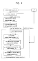
- Fig. 1 is a schematic diagram of a resonance shear measurement system in accordance with an embodiment of the present invention.
- Fig. 2 is a schematic diagram showing an example of a unit for resonance shear measurement of the system in accordance with an embodiment of the present invention.
- reference numeral 1 is a waveform generator
- 2 is a power source to which the waveform generator 1 is connected
- 3 is a resonance shear measurement unit to which the power source 2 is connected and to which an input voltage U in as an input signal is applied
- 4 is a displacement gauge such as, for example, a capacitance type displacement gauge, to which the resonance shear measurement unit 3 is connected
- 5 is a resonance shear signal analyzer to which the capacitance type displacement gauge 4 and the power source 2 are connected and to which an output voltage U out as an output signal along with the input voltage D in are applied.
- the resonance shear signal analyzer 5 includes a timer section 5A, a Fourier transformation section 5B, an amplitude spectrum generation section 5C, a normalization section 5D of amplitude (U out /U in ) to normalize U in ( ⁇ ) and U out , and a resonance shear curve producing section 5E.
- 6 is a personal computer (PC) which is connected to the waveform generator 1 and the resonance shear signal analyzer 5.
- the displacement gauge described above may be a strain gauge.
- reference numeral 10 is a resonance shear measurement unit (corresponding to the unit 3 in Fig.1 ), 11 is a cantilever, 12 is a disc holder, 13 is a white light source, 14 is a lower substrate fixed on the disc holder 12, 15 is a four-piece piezoelectric element as a horizontal driving section to drive horizontally the upper surface, 16 is an upper substrate fixed to the bottom of the four-piece piezoelectric element 15, 17 is a leaf spring to support the four-piece piezoelectric element 15, 18 is a capacitance type displacement gauge (a probe) to measure horizontal displacement ⁇ X of the leaf spring 17, (corresponding to a capacitance type displacement gauge 4 in Fig.
- the liquid may include not only a single component but also various liquid including micelle and colloid dispersion system with two or more components.
- a motor may be used as the horizontal driving section described above.
- Fig.3 is a schematic diagram of a partial configuration of a unit for resonance shear measurement of the resonance shear measurement system in accordance with a modification of the present invention.
- substrates themselves are samples 21 and 22. Without any sample sandwiched between substrates as shown in Fig.2 , a friction (lubrication) property between the sample (substrate) 21 and the sample (substrate) 22 can also be measured.
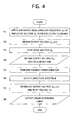
- Fig.4 is a flowchart of the resonance shear measurement.
- the horizontal axis shows an elapsed time
- the vertical axis shows an amplitude of the oscillation.
- ⁇ is angular frequency
- F( ⁇ ) is the obtained Fourier spectrum
- f (t) is the damping oscillation
- t is time.
- a measurement result of a resonance shear curve by using the resonance shear measurement method of the present invention is shown in the following in comparison with a result obtained by using the conventional method.
- Fig. 6 is a diagram showing the resonance shear curve obtained by applying Fourier transformation of the present invention to the damping oscillation shown in Fig. 5 and a curve obtained by the conventional method.
- the horizontal axis shows the oscillation frequency on the surface on one side of the sample
- the vertical axis shows an amplitude of the oscillation, which is shown by a ratio of the output voltage (U out ) measured by the capacitance type displacement gauge and the input voltage (U in ) applied to the piezoelectric element in the resonance shear measurement unit.
- the conventional method is a technique to measure point by point a response on the surface on one side of the sample to each oscillation frequency.
- Fig. 6 demonstrates that the present invention can measure the response on the surface on one side of the sample to the frequency quite well, and that the present invention is a method to measure continuously the response on the surface on one side of the sample for wide range of oscillation frequency in a short time.
- a change of the rheological properties of the sample, friction/lubrication properties, the interaction between the sample and the solid substrates, and the like can be measured.
- the substrate itself as a sample without any other sample sandwiched inbetween, mutual friction (lubrication) properties can be measured.
- the surface may be modified by an adsorption method or a chemical modification method (LB (Langmuir-Brodgett) modification method) .
- the frequency response of the sample can be measured not only by applying oscillation to the surface on one side of the sample in the horizontal direction but also by applying oscillation to the direction perpendicular to the surface.
- twin-path type shear stress measurement will be described as the other embodiment of the present invention.
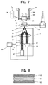
- Fig. 7 is a schematic diagram showing a twin-path type apparatus for shear stress measurement in accordance with the other embodiment of the present invention.
- reference numeral 31 is a resonance shear measurement unit
- 32 is a four-piece piezoelectric element to drive an upper surface horizontally
- 33 is a leaf spring to support the four-piece piezoelectric element 32
- 34 is a capacitance type displacement gauge (probe) to measure a horizontal displacement ⁇ x of the leaf spring 33
- 35 is an upper substrate which is fixed to the bottom of the four-piece piezoelectric element 32.
- an unit 40 to fix a bottom disk holder 42 holds the bottom disk holder 42 at a front edge of the leaf spring 41, and a mirror 43 is provided on a back side of the bottom disk holder 42.
- a driving apparatus for example, a motor (not shown) to drive the leaf spring 41 vertically.
- 51 is a twin-path type measurement apparatus for a distance between surfaces, which comprises a laser light source 52, a diffraction grating 53 which receives the laser light from the laser light source 52 and divides it into a measuring light and a reference light, a piezoelectric element 54 to adjust the diffraction grating 53, a lens 55 to accept light from the diffraction grating 53, a fixed mirror 56 to receive the reference light which is a part of the laser light, a diffraction grating 57 which receives through the lens 55 the reference light reflected by the fixed mirror 56 and the measuring light reflected by the mirror 43 provided on a back side of the bottom disk holder, a photodiode 58 to receive the light passing through the diffraction grating 57, and a personal computer 59 connected to the piezoelectric element 54 and the photodiode 58.
- Fig. 8 is a schematic diagram of a sample used in an applicational example of a twin-path type apparatus for shear stress measurement of the present invention
- Fig. 9 shows a chemical formula of a liquid crystal (4-cyano-4-hexyl biphenyl, 6CB)
- Fig. 10 shows the resonance curves measured by the twin-path type apparatus for shear stress measurement of the present invention for a liquid crystal (4-cyano-4-hexyl biphenyl, 6CB) as a sample.
- micas 62, 63 are disposed above and below the liquid crystal (4-cyano-4-hexylbiphenyl, 6CB) 61 which is a sample. That is, the liquid crystal 61 as a sample is disposed to be sandwiched between the mica 62 which is an upper substrate 35 and the mica 63 which is the bottom disk holder 42.
- the horizontal axis is an angular frequency (s -1 ) on the upper surface of the sample
- the vertical axis is a ratio of the output voltage (U out ) measured by the capacitance type displacement gauge to the input voltage (U in ) applied to the piezoelectric element of the resonance shear precise measurement unit.
- Solid lines shows resonance peaks for different distances of surfaces of the sample, the distances being shown on a side of each of the curves.
- the distance between surfaces is defined to be 0nm when no change of the distance between surfaces was observed when driving upward the bottom disk holder by a driving apparatus. By changing the distance between the surfaces, change of the resonance curve was observed.
- a plurality of peaks at 0nm shows cases of a constant distance between the surfaces with different load.
- the present invention enables measuring a change in rheological properties of the sample (liquid, solid, liquid crystal and the like), friction/lubrication properties, and a coupling intensity between the sample and the solid substrate while changing the thickness of the sample sandwiched between two solid substrates. Also by using the substrate itself as a sample, i,e., without any other sample sandwiched inbetween, mutual friction (lubrication) properties can be measured. Furthermore the surface may be modified by an adsorption or a chemical modification method (LB (Langmuir Blodgett) method).
- the present invention does not need for a light to pass through the substrate and the sample because the reflection of a laser light is used, thereby enabling to measure the distance between surfaces and to measure the rheological property and the friction/lubrication property of the sample at different distances even if an opaque substrate and/or an opaque sample are used.
- the resonance shear measuring method of the present invention as described in the first embodiment is suitable to measure simply, conveniently, and precisely properties of liquid thin films with thickness of a nanometer scale between solid surfaces.
- the twin-path type apparatus for shear stress measurement of the present invention as described in the second embodiment can be used as a twin-path type apparatus for shear stress measurement which can measure shear stress precisely by using the twin-path method enabling to measure a distance between opaque substrates.
- the apparatus in the second embodiment is also suitable to measure simply, conveniently, and precisely properties of liquid thin films with thickness of a nanometer scale between solid surfaces.
Landscapes
- Physics & Mathematics (AREA)
- Health & Medical Sciences (AREA)
- Life Sciences & Earth Sciences (AREA)
- Chemical & Material Sciences (AREA)
- Analytical Chemistry (AREA)
- Biochemistry (AREA)
- General Health & Medical Sciences (AREA)
- General Physics & Mathematics (AREA)
- Immunology (AREA)
- Pathology (AREA)
- Investigating Strength Of Materials By Application Of Mechanical Stress (AREA)
- Measurement Of Mechanical Vibrations Or Ultrasonic Waves (AREA)
Abstract
Description
- The present invention relates a shear measurement method and an apparatus thereof which is capable of performing a desired measurement on an interface between two solid surfaces or a thin film sandwiched inbetween irrespective of their transparency, and more particularly and specifically relates to (1) a method and an apparatus for resonance shear measurement which is rapid, simple, convenient, versatile and precise in performing a measurement on a film with thickness which is liable to change or a highly volatile liquid film, and (2) a method and an apparatus to measure shear stress between two solid surfaces and a layer sandwiched inbetween including a liquid thin film, a liquid crystal thin film, or a polymer adsorption layer while changing the distance of the two solid surfaces in nanometer scale by using a measuring technique for the separation distance between the two surfaces by means of a twin-path type interferometer method.
- (1) First of all, it is important for comprehension and control of the friction and lubrication on solid surfaces and orientation and structuration of liquid molecules and liquid crystal molecules to know a shear response of a sample (such as liquid and liquid crystal) sandwiched between the solid surfaces along with change of film thickness in nanometer scale. The resonance shear measurement for measuring the shear response of a sample is a method to provide a shear by oscillating a surface on one side of a sample horizontally and to monitor its response near a resonance frequency. Plotting the shear response as a function of frequency gives a resonance curve. Resonance frequency and a resonance peak height are sensitive to the properties of the sample between the solid surfaces and immune to an oscillation noise from outside of the measurement apparatus.
- The conventional method to measure precisely the shear response of a sample sandwiched between solid surfaces is to measure the shear response of the sample to a shear while changing frequency around the resonance frequency and to plot the response as a function of frequency to obtain a resonance shear curve. This method is disclosed in
Non-Patent Document 1 shown below. - An apparatus for precise measurement of shear stress was proposed by the present inventors as described in
Patent Document 1 below. - (2) Secondly, the present inventors have proposed an apparatus for precise measurement of shear stress capable of measuring with high accuracy a rheological behavior in an ultra small space with a nano-scale dimension, as described in
Patent Document 2. - The present inventors have also proposed a surface force measurement apparatus and method capable of measuring a surface force between samples with high accuracy even if the samples are not transparent for light, as described in
Patent Document 3 below. - [Patent Document 1] Japanese Patent Publication No.
3032152 - [Patent Document 2] Japanese Patent Publication No.
3032152 - [Patent Document 3] Japanese Patent Application Publication No.
2001-108603 - [Non-Patent Document 1] Liquid Crystal, vol.6, No. 1, pp. 34-41, 2002.
- However, since shear response of a sample is measured at around the resonance frequency while changing the oscillation frequency, the conventional technique described above in (1) requires to keep the film thickness of the sample constant for a long time. It is therefore difficult to measure samples such as films with the thickness liable to change and liquid thin films with high volatility.
- Furthermore, in the conventional technique described above in (2), an apparatus for resonance shear measurement is combined with a measurement apparatus for a distance between surfaces by an optical interferometry technique making use of the fringes of equal chromatic order (FECO) to measure rheological properties and friction/lubrication properties of a sample sandwiched by the surfaces while measuring the distance between the surfaces with resolution of 0.1 nanometer. Since this technique makes use of a light passing through the surfaces, the substrate and the sample sandwiched between the substrate surfaces are limited to be optically transparent. Especially, the substrate is almost limited to mica for a practical use, and an alternative substrate for an experimental test is also limited to a thin plate of sapphire and glass with thickness of about 2 micrometer.
- In addition, the twin-path type surface forces apparatus as described in
Patent Document 3 measures a force exerted to upper and lower surfaces and cannot perform a shear measurement. - The purpose of the present invention is to provide a shear measurement method and an apparatus thereof which can perform a desirable measurement not only on a transparent sample but also on an opaque sample.
- More concrete description is given in the following. By taking the situation described above into account, the first purpose of the present invention is to provide a method for resonance shear measurement, the method being capable of performing simple and short-time measurement by obtaining a resonance shear curve by Fourier-transforming a damping curve of an oscillation on a surface on one side of a sample during a measurement of a shear response from the sample.
- In addition, by taking account of the situation described above, the second purpose of the present invention is to provide a twin-path type measurement method of shear stress and an apparatus thereof which enables a precise measurement of shear stress by making use of a twin-path method which is capable of measuring a distance between the substrates even when the substrates or a sample are not transparent.
- To achieve the purpose describe above, the present invention provides:
- [1] a resonance shear measuring method to measure a shear response of a sample sandwiched between solid surfaces in a resonance shear measurement unit, along with a change in film thickness, the method including steps of:
- applying an input signal Uin to a horizontal driving section of the resonance shear measurement unit,
- detecting an oscillation of a surface on one side of the sample sandwiched between the solid surfaces set in the resonance shear measurement unit by means of a displacement gauge, the output of detection being an output signal Uout , and,
- applying the output signal Uout along with the input signal Uin to a resonance shear signal analyzer,
- [2] a resonance shear measuring method to measure a shear response of a sample which is solid surfaces themselves without any other sample sandwiched between the solid surfaces in a resonance shear measurement unit, along with a change in film thickness, the method including steps of:
- applying an input signal Uin to a horizontal driving section of the resonance shear measurement unit,
- detecting an oscillation of a surface on one side of the sample in the resonance shear measurement unit by means of a displacement gauge, the output of detection being an output signal Uout and,
- applying the output signal Uout along with the input signal Uin to a resonance shear signal analyzer,
- [3] the resonance shear measuring method according to item [1], wherein the sample is a thin film.
- [4] the resonance shear measuring method according to item [1], wherein the sample is liquid.
- [5] the resonance shear measuring method according to item [1], wherein the sample is a liquid crystal.
- [6] the resonance shear measuring method according to item [1], wherein the sample has a thickness in nanometer size.
- [7] the resonance shear measuring method according to item [1] or [2], wherein the sample has a surface modified by an adsorption or a chemical modification method.
- [8] the resonance shear measuring method according to item [1] or [2], wherein the resonance shear curve is a frequency characteristics of shear response of the sample.
- [9] an apparatus for resonance shear measurement including:
- a waveform generator;
- a power source to which the waveform generator is connected;
- a resonance shear measurement unit to which the power source is connected and an input signal Uin is applied;
- a displacement gauge to which the resonance shear measurement unit is connected;
- a resonance shear signal analyzer to which the displacement gauge and the power source are connected and to which an output signal Uout along with an input signal Uin are applied, the resonance shear signal analyzer including:
- (a) a timer section,
- (b) a Fourier transformation section to which the timer section and the displacement gauge are connected,
- (c) an amplitude spectrum generation section to which the Fourier transformation section is connected,
- (d) a normalization section of amplitude (Uout /Uin),
- (e) a resonance shear curve producing section; and
- a computer to which the waveform generator and the resonance shear signal analyzer are connected.
- [10] a twin-path type shear stress measurement method, wherein a shear stress measurement of a sample is performed by a combination of two methods: one method being a twin-path type measurement method for a distance between surfaces of the sample by irradiating a laser light to a mirror attached to a back side of a bottom disk holder and by detecting a phase change of the reflected light from the mirror, and the other method being the measurement method to measure rheological properties and friction/lubrication properties of the sample from a resonance curve.
- [11] a twin-path type apparatus for shear stress measurement including:
- (a) a precise shear device to give a horizontal displacement to a top disk holder,
- (b) a displacement gauge to detect the horizontal displacement of the top disk holder,
- (c) a fixing unit for fixing a lower surface of the sample, the unit comprising a leaf spring which holds at the front end a bottom disk holder, and a mirror disposed on a back side of the bottom disk holder,
- (d) a driving apparatus to drive upward and downward the bottom disk holder by driving the fixing unit for fixing the bottom disk holder,
- (e) a twin-path type measurement unit for measuring a distance between surfaces, the unit irradiating a laser light to the mirror and measuring a distance between the upper surface of the sample and the lower surface of the sample based on a phase change of a reflected light from the mirror,
- [12] the twin-path type apparatus for shear stress measurement according to item [11], wherein measurement on the rheological properties and friction/lubrication properties of the sample is performed based on a resonance curve of the sample.
- [13] the twin-path type apparatus for shear stress measurement according to item [11] or [12], wherein the sample is a transparent sample or an opaque sample.
- [14] the twin-path type apparatus for shear stress measurement according to item [11] or [12], wherein the sample is a liquid thin film.
- [15] the twin-path type apparatus for shear stress measurement according to item [11] or [12], wherein the sample is a liquid crystal thin film.
- [16] the twin-path type apparatus for shear stress measurement according to item [11] or [12], wherein the sample is an adsorption layer such as polymer and/or surfactant or a chemically modified film.
- [17] the twin-path type apparatus for shear stress measurement according to item [11] or [12], wherein either one or both of the top disk holder and the bottom disk holder are opaque substrates.
-
- [
Fig.1] Fig. 1 is a schematic diagram of a resonance shear measurement system in accordance with an embodiment of the present invention. - [
Fig.2] Fig. 2 is a schematic diagram showing an example of a resonance shear measurement unit of the resonance shear measurement system in accordance with an embodiment of the present invention. - [
Fig.3] Fig. 3 is a schematic diagram of a partial configuration of a resonance shear measurement unit of the resonance shear measurement system in accordance with a modification of the present invention. - [
Fig.4] Fig. 4 is a flowchart of the resonance shear measurement in accordance with an embodiment of the present invention. - [
Fig.5] Fig. 5 shows an example of a damping oscillation of a surface on one side of a sample measured by setting the sample to the resonance shear measurement unit in accordance with the present invention. - [
Fig.6] Fig. 6 shows a resonance shear curve obtained by applying Fourier transformation of the present invention to the damping oscillation as shown inFIG.5 and a curve obtained by the conventional method. - [
Fig.7] Fig. 7 is a schematic diagram of a twin-path type apparatus for sear stress measurement in accordance with the other embodiment of the present invention. - [
Fig.8] Fig.8 is a schematic diagram of a sample used in an applicational example of a twin-path type apparatus for shear stress measurement in accordance with the other embodiment of the present invention. - [
Fig. 9] Fig. 9 shows a chemical formula of a liquid crystal (4-cyano-4-hexyl biphenyl, 6CB) as a sample sandwiched between surfaces of mica in accordance with the other embodiment of the present invention. - [
Fig. 10] Fig. 10 shows a measurement result by the twin-path type apparatus for shear stress measurement of the present invention for a liquid crystal (4-cyano-4-hexyl biphenyl, 6CB) as a sample in accordance with another embodiment of the present invention. - A first embodiment of the present invention provides a resonance shear measuring method which measures a shear response of a sample sandwiched between solid surfaces in a resonance shear measurement unit, along with a change in film thickness, including steps of : applying an input signal Uin to a piezoelectric element of the resonance shear measurement unit, detecting an oscillation of a surface on one side of the sample sandwiched between the solid surfaces set in the resonance shear measurement unit by means of a displacement gauge, the output of detection being an output signal Uout, and applying the output signal Uout along with the input signal Uin to a resonance shear signal analyzer. In the method, a resonance shear curve is obtained by performing a Fourier transformation of a damping curve of the oscillation of the surface on one side of the sample.
- A second embodiment of the present invention provides a twin-path type apparatus for shear stress measurement which includes a precise shear device to give a horizontal displacement to an upper surface of a sample, a displacement gauge to detect the horizontal displacement of the upper surface of the sample, a fixing unit for fixing a lower surface of the sample which includes a leaf spring which holds at the front end the lower surface of the sample, and a mirror disposed on a back side of a bottom disk holder, a driving apparatus to drive upward and downward the lower surface of the sample by driving the fixing unit for fixing the lower surface of the sample, and a twin-path type measurement unit for measuring a distance between surfaces based on a phase change of a reflected light from the mirror. In the apparatus, rheological properties and friction/lubrication properties of the sample are measured per distance between the upper surface of the sample and the lower surface of the sample.
- Various embodiments of the present invention will be described in more detail in the following.
-
Fig. 1 is a schematic diagram of a resonance shear measurement system in accordance with an embodiment of the present invention.Fig. 2 is a schematic diagram showing an example of a unit for resonance shear measurement of the system in accordance with an embodiment of the present invention. In these figures,reference numeral 1 is a waveform generator, 2 is a power source to which thewaveform generator 1 is connected, 3 is a resonance shear measurement unit to which thepower source 2 is connected and to which an input voltage Uin as an input signal is applied, 4 is a displacement gauge such as, for example, a capacitance type displacement gauge, to which the resonanceshear measurement unit 3 is connected, 5 is a resonance shear signal analyzer to which the capacitancetype displacement gauge 4 and thepower source 2 are connected and to which an output voltage Uout as an output signal along with the input voltage Din are applied. The resonanceshear signal analyzer 5 includes atimer section 5A, aFourier transformation section 5B, an amplitudespectrum generation section 5C, anormalization section 5D of amplitude (Uout /Uin) to normalize Uin (ω) and Uout, and a resonance shear curve producing section 5E. 6 is a personal computer (PC) which is connected to thewaveform generator 1 and the resonanceshear signal analyzer 5.
In addition, the displacement gauge described above may be a strain gauge. - In
Fig. 2 ,reference numeral 10 is a resonance shear measurement unit (corresponding to theunit 3 inFig.1 ), 11 is a cantilever, 12 is a disc holder, 13 is a white light source, 14 is a lower substrate fixed on thedisc holder piezoelectric element piezoelectric element leaf spring 17, (corresponding to a capacitancetype displacement gauge 4 inFig. 1 ), and 19 is a sample (solid, liquid, and liquid crystal and the like) which is an object for measurement of the shear response. The liquid may include not only a single component but also various liquid including micelle and colloid dispersion system with two or more components. Furthermore, a motor may be used as the horizontal driving section described above. -
Fig.3 is a schematic diagram of a partial configuration of a unit for resonance shear measurement of the resonance shear measurement system in accordance with a modification of the present invention. - In this example, substrates themselves are
samples Fig.2 , a friction (lubrication) property between the sample (substrate) 21 and the sample (substrate) 22 can also be measured. -
Fig.4 is a flowchart of the resonance shear measurement. - (1) First of a11, apply a sinusoidal wave (angular frequency ω) of an amplitude voltage Uin as shown in
Fig. 1 to the piezoelectric element (the four-piecepiezoelectric element 15 as shown inFig. 2 ). (step S1). - (2) Obtain an output voltage Uout(ω). (step S2).
- (3) Stop the input voltage Uin. (step S3).
- (4) Obtain the output voltage Uout along with its elapsed time. (step S4)
- (5) Perform a Fourier transformation. (step S5).
- (6) Output an amplitude spectrum. (step S5).
- (7) Normalize the output voltage Uout (ω) and input voltage Uin. (step S7).
- (8) Output a resonance shear curve. (step S8).
- When a measurement is performed for a sample set in the resonance shear measurement unit described above, the damping oscillation on the surface on one side of the sample exhibits a curve shown in
Fig. 5 . - Here, the horizontal axis shows an elapsed time, and the vertical axis shows an amplitude of the oscillation. Fourier transformation expressed by the following Equation (1) is applied to the damping oscillation.
-

- By taking the amplitude spectrum, a resonance shear curve can be obtained. Here, ω is angular frequency, F(ω) is the obtained Fourier spectrum, f (t) is the damping oscillation, and t is time.
- A measurement result of a resonance shear curve by using the resonance shear measurement method of the present invention is shown in the following in comparison with a result obtained by using the conventional method.
-
Fig. 6 is a diagram showing the resonance shear curve obtained by applying Fourier transformation of the present invention to the damping oscillation shown inFig. 5 and a curve obtained by the conventional method. - Here, the horizontal axis shows the oscillation frequency on the surface on one side of the sample, and the vertical axis shows an amplitude of the oscillation, which is shown by a ratio of the output voltage (Uout) measured by the capacitance type displacement gauge and the input voltage (Uin) applied to the piezoelectric element in the resonance shear measurement unit. The conventional method is a technique to measure point by point a response on the surface on one side of the sample to each oscillation frequency.
Fig. 6 demonstrates that the present invention can measure the response on the surface on one side of the sample to the frequency quite well, and that the present invention is a method to measure continuously the response on the surface on one side of the sample for wide range of oscillation frequency in a short time. - In accordance with the present invention, by sandwiching a sample (solid, liquid, liquid crystal and the like) between two solid substrates, and by changing the thickness thereof, a change of the rheological properties of the sample, friction/lubrication properties, the interaction between the sample and the solid substrates, and the like can be measured. Furthermore, by using the substrate itself as a sample without any other sample sandwiched inbetween, mutual friction (lubrication) properties can be measured. Moreover, the surface may be modified by an adsorption method or a chemical modification method (LB (Langmuir-Brodgett) modification method) . In addition, the frequency response of the sample can be measured not only by applying oscillation to the surface on one side of the sample in the horizontal direction but also by applying oscillation to the direction perpendicular to the surface.
- In accordance with the present invention, it is not necessary to measure the shear response at each of the oscillation frequency point by point as in the conventional technology, and the measurement of the resonance shear curve can be performed, with ease, in short time, and with high precision.
- In the following, a twin-path type shear stress measurement will be described as the other embodiment of the present invention.
-
Fig. 7 is a schematic diagram showing a twin-path type apparatus for shear stress measurement in accordance with the other embodiment of the present invention. - In this figure,
reference numeral 31 is a resonance shear measurement unit, 32 is a four-piece piezoelectric element to drive an upper surface horizontally, 33 is a leaf spring to support the four-piecepiezoelectric element leaf spring piezoelectric element 32. - Also, an
unit 40 to fix abottom disk holder 42 holds thebottom disk holder 42 at a front edge of theleaf spring 41, and amirror 43 is provided on a back side of thebottom disk holder 42. On the other hand, on the base part of theleaf spring 41, there is provided a driving apparatus (for example, a motor (not shown)) to drive theleaf spring 41 vertically. - Furthermore, 51 is a twin-path type measurement apparatus for a distance between surfaces, which comprises a
laser light source 52, adiffraction grating 53 which receives the laser light from thelaser light source 52 and divides it into a measuring light and a reference light, apiezoelectric element 54 to adjust thediffraction grating 53, alens 55 to accept light from thediffraction grating 53, a fixedmirror 56 to receive the reference light which is a part of the laser light, adiffraction grating 57 which receives through thelens 55 the reference light reflected by the fixedmirror 56 and the measuring light reflected by themirror 43 provided on a back side of the bottom disk holder, aphotodiode 58 to receive the light passing through thediffraction grating 57, and apersonal computer 59 connected to thepiezoelectric element 54 and thephotodiode 58. - By this configuration, a change of a distance between surfaces sandwiching the sample A can be measured by the twin-path type measurement apparatus for a distance between
surfaces 51, whereas the upper surface of the sample A is attached to the resonance shearprecise measurement unit 31 which measures the rheological property and the friction/lubrication property of the sample, thereby enabling measurement of the shear stress precisely. -
Fig. 8 is a schematic diagram of a sample used in an applicational example of a twin-path type apparatus for shear stress measurement of the present invention,Fig. 9 shows a chemical formula of a liquid crystal (4-cyano-4-hexyl biphenyl, 6CB), andFig. 10 shows the resonance curves measured by the twin-path type apparatus for shear stress measurement of the present invention for a liquid crystal (4-cyano-4-hexyl biphenyl, 6CB) as a sample. - As shown in
Fig. 8 , micas 62, 63 are disposed above and below the liquid crystal (4-cyano-4-hexylbiphenyl, 6CB) 61 which is a sample. That is, theliquid crystal 61 as a sample is disposed to be sandwiched between themica 62 which is anupper substrate 35 and themica 63 which is thebottom disk holder 42. - The chemical formula of a liquid crystal (4-cyano-4-hexyl biphenyl, 6CB) as a sample sandwiched between mica surfaces is shown in
Fig. 9 . - In the
Fig. 10 , the horizontal axis is an angular frequency (s-1) on the upper surface of the sample, and the vertical axis is a ratio of the output voltage (Uout) measured by the capacitance type displacement gauge to the input voltage (Uin) applied to the piezoelectric element of the resonance shear precise measurement unit. In addition to the measurement result for the liquid crystal as a sample, a measurement result for the surfaces of the holding elements in a separated condition with no liquid crystal (sample) therebetween (in air (after separation)), and a measurement result for the surfaces of the holding elements in close contact with each other with no liquid crystal (sample) therebetween (in air (micas in contact)) are depicted for comparison. Solid lines shows resonance peaks for different distances of surfaces of the sample, the distances being shown on a side of each of the curves. Here, the distance between surfaces is defined to be 0nm when no change of the distance between surfaces was observed when driving upward the bottom disk holder by a driving apparatus. By changing the distance between the surfaces, change of the resonance curve was observed. A plurality of peaks at 0nm shows cases of a constant distance between the surfaces with different load. - Thus, the present invention enables measuring a change in rheological properties of the sample (liquid, solid, liquid crystal and the like), friction/lubrication properties, and a coupling intensity between the sample and the solid substrate while changing the thickness of the sample sandwiched between two solid substrates. Also by using the substrate itself as a sample, i,e., without any other sample sandwiched inbetween, mutual friction (lubrication) properties can be measured. Furthermore the surface may be modified by an adsorption or a chemical modification method (LB (Langmuir Blodgett) method).
- Furthermore, the present invention does not need for a light to pass through the substrate and the sample because the reflection of a laser light is used, thereby enabling to measure the distance between surfaces and to measure the rheological property and the friction/lubrication property of the sample at different distances even if an opaque substrate and/or an opaque sample are used.
- The present invention is not limited to the embodiments described above, but various modifications may be possible based on the essence of the present invention. These modifications are not excluded from the scope of the present invention.
- The resonance shear measuring method of the present invention as described in the first embodiment is suitable to measure simply, conveniently, and precisely properties of liquid thin films with thickness of a nanometer scale between solid surfaces.
- The twin-path type apparatus for shear stress measurement of the present invention as described in the second embodiment can be used as a twin-path type apparatus for shear stress measurement which can measure shear stress precisely by using the twin-path method enabling to measure a distance between opaque substrates. Similarly to the resonance shear measuring method in the first embodiment, the apparatus in the second embodiment is also suitable to measure simply, conveniently, and precisely properties of liquid thin films with thickness of a nanometer scale between solid surfaces.
Claims (17)
- A resonance shear measuring method to measure a shear response of a sample sandwiched between solid surfaces in a resonance shear measurement unit, along with a change in film thickness, the method comprising steps of:applying an input signal Uin to a horizontal driving section of the resonance shear measurement unit,detecting an oscillation of a surface on one side of the sample sandwiched between the solid surfaces set in the resonance shear measurement unit by means of a displacement gauge, the output of detection being an output signal Uout, and,applying the output signal Uout along with the input signal Uin to a resonance shear signal analyzer,wherein a resonance shear curve is obtained by performing a Fourier transformation of a damping curve of the oscillation of the surface on one side of the sample.
- A resonance shear measuring method to measure a shear response of a sample which is solid surfaces themselves without any other sample sandwiched between the solid surfaces in a resonance shear measurement unit, along with a change in film thickness, the method comprising steps of:applying an input signal Uin to a horizontal driving section of the resonance shear measurement unit,detecting an oscillation of a surface on one side of the sample in the resonance shear measurement unit by means of a displacement gauge, the output of detection being an output signal Uout, and,applying the output signal Uout along with the input signal Uin to a resonance shear signal analyzer,wherein a resonance shear curve is obtained by performing a Fourier transformation of a damping curve of the oscillation of the surface on one side of the sample.
- The resonance shear measuring method according to claim 1, wherein the sample is a thin film.
- The resonance shear measuring method according to claim 1, wherein the sample is liquid.
- The resonance shear measuring method according to claim 1, wherein the sample is a liquid crystal.
- The resonance shear measuring method according to claim 1, wherein the sample has a thickness in nanometer size.
- The resonance shear measuring method according to claim 1 or 2, wherein the sample has a surface modified by an adsorption or a chemical modification method.
- The resonance shear measuring method according to claim 1 or 2, wherein the resonance shear curve is a frequency characteristics of shear response of the sample.
- An apparatus for resonance shear measurement comprising:a waveform generator;a power source to which the waveform generator is connected;a resonance shear measurement unit to which the power source is connected and an input signal Uin is applied;a displacement gauge to which the resonance shear measurement unit is connected;a resonance shear signal analyzer to which the displacement gauge and the power source are connected and to which an output signal Uout along with an input signal Uin are applied, the resonance shear signal analyzer comprising:(a) a timer section,(b) a Fourier transformation section to which the timer section and the displacement gauge are connected,(c) an amplitude spectrum generation section to which the Fourier transformation section is connected,(d) a normalization section of amplitude (Uout /Uin),(e) a resonance shear curve producing section; anda computer to which the waveform generator and the resonance shear signal analyzer are connected.
- A twin-path type shear stress measurement method, wherein a shear stress measurement of a sample is performed by a combination of two methods: one method being a twin-path type measurement method for a distance between surfaces of the sample by irradiating a laser light to a mirror attached to a back side of a bottom disk holder and by detecting a phase change of the reflected light from the mirror, and the other method being the measurement method to measure rheological properties and friction/lubrication properties of the sample from a resonance curve.
- A twin-path type apparatus for shear stress measurement comprising:(a) a precise shear device to give a horizontal displacement to a top disk holder,(b) a displacement gauge to detect the horizontal displacement of the top disk holder,(c) a fixing unit for fixing a lower surface of the sample, the unit comprising a leaf spring which holds at the front end a bottom disk holder, and a mirror disposed on a back side of the bottom disk holder,(d) a driving apparatus to drive upward and downward the bottom disk holder by driving the fixing unit for fixing the lower surface of the sample,(e) a twin-path type measurement unit for measuring a distance between surfaces, the unit irradiating a laser light to the mirror and measuring a distance between the upper surface of the sample and the lower surface of the sample based on a phase change of a reflected light from the mirror,wherein rheological properties and friction/lubrication properties of the sample are measured per distance between the upper surface of the sample and the lower surface of the sample.
- The twin-path type apparatus for shear stress measurement according to claim 11, wherein measurement on the rheological properties and friction/lubrication properties of the sample is performed based on a resonance curve of the sample.
- The twin-path type apparatus for shear stress measurement according to claim 11 or 12, wherein the sample is a transparent sample or an opaque sample.
- The twin-path type apparatus for shear stress measurement according to claim 11 or 12, wherein the sample is a liquid thin film.
- The twin-path type apparatus for shear stress measurement according to claim 11 or 12, wherein the sample is a liquid crystal thin film.
- The twin-path type apparatus for shear stress measurement according to claim 11 or 12, wherein the sample is an adsorption layer such as polymer and/or surfactant or a chemically modified film.
- The twin-path type apparatus for shear stress measurement according to claim 11 or 12, wherein either one or both of the top disk holder and the bottom disk holder are opaque substrates.
Applications Claiming Priority (3)
| Application Number | Priority Date | Filing Date | Title |
|---|---|---|---|
| JP2005282769 | 2005-09-28 | ||
| JP2005282768 | 2005-09-28 | ||
| PCT/JP2006/319103 WO2007037241A1 (en) | 2005-09-28 | 2006-09-27 | Shear measuring method and its device |
Publications (2)
| Publication Number | Publication Date |
|---|---|
| EP1942331A1 true EP1942331A1 (en) | 2008-07-09 |
| EP1942331A4 EP1942331A4 (en) | 2015-09-02 |
Family
ID=37899665
Family Applications (1)
| Application Number | Title | Priority Date | Filing Date |
|---|---|---|---|
| EP06810594.9A Withdrawn EP1942331A4 (en) | 2005-09-28 | 2006-09-27 | SHEAR MEASUREMENT METHOD AND ITS DEVICE |
Country Status (5)
| Country | Link |
|---|---|
| US (1) | US7845231B2 (en) |
| EP (1) | EP1942331A4 (en) |
| JP (1) | JP4615568B2 (en) |
| CN (2) | CN102374967B (en) |
| WO (1) | WO2007037241A1 (en) |
Cited By (2)
| Publication number | Priority date | Publication date | Assignee | Title |
|---|---|---|---|---|
| CN102221499A (en) * | 2011-03-29 | 2011-10-19 | 天津大学 | Alignment loading device used for stretching test of nanoscale, micron-size thin film materials |
| CN113614508A (en) * | 2019-03-28 | 2021-11-05 | 国立大学法人东北大学 | Resonance shear measuring device |
Families Citing this family (7)
| Publication number | Priority date | Publication date | Assignee | Title |
|---|---|---|---|---|
| JP5263784B2 (en) * | 2009-06-29 | 2013-08-14 | 独立行政法人産業技術総合研究所 | Viscosity measurement device for thin film liquid |
| JP2020066682A (en) * | 2018-10-25 | 2020-04-30 | 出光興産株式会社 | Lubricating base oil, lubricating oil composition, and method of using lubricating oil composition |
| JP7318996B2 (en) * | 2019-03-28 | 2023-08-01 | 国立大学法人東北大学 | Resonance shear measurement device |
| JP7154660B2 (en) * | 2019-12-18 | 2022-10-18 | 国立大学法人東北大学 | Viscometer and viscosity measurement method |
| JP7477171B2 (en) * | 2021-02-09 | 2024-05-01 | 国立大学法人東北大学 | Resonance shear measuring device and method of using same, and viscometer and method of using same |
| CN114371124B (en) * | 2022-01-14 | 2024-01-12 | 安徽理工大学 | A droplet adhesion detection system based on micro-cantilever beam |
| CN116204004B (en) * | 2023-03-06 | 2026-05-26 | 上海御微半导体技术有限公司 | A vibration suppression method, control board, device, and storage medium. |
Family Cites Families (18)
| Publication number | Priority date | Publication date | Assignee | Title |
|---|---|---|---|---|
| DE2733099C2 (en) * | 1977-07-22 | 1979-12-13 | Brabender Ohg, 4100 Duisburg | Rotational viscometer |
| JPS5826552B2 (en) * | 1977-11-30 | 1983-06-03 | 新日本製鐵株式会社 | Internal friction measuring device using torsional vibration |
| JPH0610650B2 (en) | 1984-11-30 | 1994-02-09 | 株式会社島津製作所 | Viscosity measuring device |
| JPH0684884B2 (en) | 1986-08-14 | 1994-10-26 | オムロン株式会社 | Waveguide optical displacement sensor |
| US5052228A (en) * | 1986-11-19 | 1991-10-01 | Massachusetts Institute Of Technology | Shear stress measuring device |
| JPS63135808A (en) | 1986-11-27 | 1988-06-08 | Inoue Japax Res Inc | Length measuring device |
| JP3293666B2 (en) | 1992-10-08 | 2002-06-17 | 株式会社トプコン | Non-contact optical type distance measuring device between two surfaces |
| JP3032152B2 (en) * | 1996-03-25 | 2000-04-10 | 科学技術振興事業団 | Precise shear stress measuring device |
| DE19733114C2 (en) * | 1997-07-31 | 1999-08-05 | Max Planck Gesellschaft | Method and device for recording rheological material properties |
| JP3933823B2 (en) * | 1999-10-14 | 2007-06-20 | 独立行政法人科学技術振興機構 | Surface force measuring apparatus and method |
| CN1149394C (en) * | 2000-03-17 | 2004-05-12 | 中山大学 | A Shear Wave Resonance Absorption Spectrometer for Liquid Film |
| US6484567B1 (en) * | 2000-08-03 | 2002-11-26 | Symyx Technologies, Inc. | Rheometer for rapidly measuring small quantity samples |
| CN100402995C (en) * | 2001-11-02 | 2008-07-16 | 中山大学 | Tube type liquid and soft matter shear wave resonance absorption spectrometer |
| AU2002950831A0 (en) * | 2002-08-16 | 2002-09-12 | Gbc Scientific Equipment Pty Ltd | Rheometer |
| WO2004106844A2 (en) * | 2003-05-21 | 2004-12-09 | University Of Wyoming | Oscillatory motion based measurement method and sensor for measuring wall shear stress due to fluid flow |
| US7451666B2 (en) * | 2006-01-13 | 2008-11-18 | Jr Johanson, Inc. | Apparatus and test procedure for measuring the cohesive, adhesive, and frictional properties of bulk granular solids |
| FR2902879B1 (en) * | 2006-06-22 | 2008-10-10 | Michelin Soc Tech | ORTHOGONAL RHEOMETER |
| GB0703004D0 (en) * | 2007-02-15 | 2007-03-28 | Uws Ventures Ltd | Apparatus and method for measuring rheological properties of blood |
-
2006
- 2006-09-27 EP EP06810594.9A patent/EP1942331A4/en not_active Withdrawn
- 2006-09-27 WO PCT/JP2006/319103 patent/WO2007037241A1/en not_active Ceased
- 2006-09-27 JP JP2007537629A patent/JP4615568B2/en active Active
- 2006-09-27 CN CN201110280838.7A patent/CN102374967B/en active Active
- 2006-09-27 US US12/088,046 patent/US7845231B2/en active Active
- 2006-09-27 CN CN2006800361588A patent/CN101278184B/en active Active
Non-Patent Citations (1)
| Title |
|---|
| See references of WO2007037241A1 * |
Cited By (6)
| Publication number | Priority date | Publication date | Assignee | Title |
|---|---|---|---|---|
| CN102221499A (en) * | 2011-03-29 | 2011-10-19 | 天津大学 | Alignment loading device used for stretching test of nanoscale, micron-size thin film materials |
| CN102221499B (en) * | 2011-03-29 | 2012-10-03 | 天津大学 | Alignment loading device used for stretching test of nanoscale, micron-size thin film materials |
| CN113614508A (en) * | 2019-03-28 | 2021-11-05 | 国立大学法人东北大学 | Resonance shear measuring device |
| US20220155202A1 (en) * | 2019-03-28 | 2022-05-19 | Tohoku University | Resonance shear measurement device |
| EP3951350A4 (en) * | 2019-03-28 | 2022-11-16 | Tohoku University | RESONANCE SHEAR MEASUREMENT DEVICE |
| US11927517B2 (en) | 2019-03-28 | 2024-03-12 | Tohoku University | Resonance shear measurement device |
Also Published As
| Publication number | Publication date |
|---|---|
| CN101278184B (en) | 2012-07-04 |
| EP1942331A4 (en) | 2015-09-02 |
| JP4615568B2 (en) | 2011-01-19 |
| JPWO2007037241A1 (en) | 2009-04-09 |
| US7845231B2 (en) | 2010-12-07 |
| WO2007037241A1 (en) | 2007-04-05 |
| CN102374967B (en) | 2014-11-05 |
| CN102374967A (en) | 2012-03-14 |
| CN101278184A (en) | 2008-10-01 |
| US20090145231A1 (en) | 2009-06-11 |
Similar Documents
| Publication | Publication Date | Title |
|---|---|---|
| Claesson et al. | Techniques for measuring surface forces | |
| Mahaffy et al. | Scanning probe-based frequency-dependent microrheology of polymer gels and biological cells | |
| Hough et al. | Correlated motions of two hydrodynamically coupled particles confined in separate quadratic potential wells | |
| JP2002082043A (en) | Rheometer for quick measurement of small samples | |
| US12098990B2 (en) | Rheometer | |
| US7845231B2 (en) | Shear measuring method and its device | |
| Cicuta et al. | Recent developments of surface light scattering as a tool for optical-rheology of polymer monolayers | |
| Dhinojwala et al. | Micron-gap rheo-optics with parallel plates | |
| US11927517B2 (en) | Resonance shear measurement device | |
| JP3032152B2 (en) | Precise shear stress measuring device | |
| US5705738A (en) | Precise shear-stress measurement apparatus | |
| De Pasquale | Experimental analysis of viscous and material damping in microstructures through the interferometric microscopy technique with climatic chamber | |
| JP2007163296A (en) | Method and apparatus for measuring height of spacer for adjusting distance between substrates of liquid crystal panel | |
| Scuor et al. | Dynamic characterization of MEMS cantilevers in liquid environment using a low-cost optical system | |
| CN104990873B (en) | The method that on-line measurement lubricates interface friction chemical property | |
| JP7477171B2 (en) | Resonance shear measuring device and method of using same, and viscometer and method of using same | |
| CN206906221U (en) | A kind of device for the tribology for studying monolayer | |
| Sugiyama et al. | Time-resolved step-scan infrared imaging system utilizing a linear array detector | |
| Patil et al. | Measurement of nanoscale interfacial contact area using vibrational spectroscopy | |
| Sakai et al. | Laser excitation of high-frequency capillary waves | |
| JP7318996B2 (en) | Resonance shear measurement device | |
| Bellon | Exploring nano-mechanics through thermal fluctuations | |
| Mere et al. | On-chip silicon-photonics based integrated vibrometer | |
| McKeith et al. | An interferometric technique for the electromechanical calibration of piezoelectric transducers | |
| Jalisse et al. | The soft-membrane surface forces apparatus |
Legal Events
| Date | Code | Title | Description |
|---|---|---|---|
| PUAI | Public reference made under article 153(3) epc to a published international application that has entered the european phase |
Free format text: ORIGINAL CODE: 0009012 |
|
| 17P | Request for examination filed |
Effective date: 20080331 |
|
| AK | Designated contracting states |
Kind code of ref document: A1 Designated state(s): AT BE BG CH CY CZ DE DK EE ES FI FR GB GR HU IE IS IT LI LT LU LV MC NL PL PT RO SE SI SK TR |
|
| DAX | Request for extension of the european patent (deleted) | ||
| RA4 | Supplementary search report drawn up and despatched (corrected) |
Effective date: 20150731 |
|
| RIC1 | Information provided on ipc code assigned before grant |
Ipc: G01N 19/04 20060101AFI20150727BHEP Ipc: G01L 5/00 20060101ALN20150727BHEP Ipc: G01N 11/00 20060101ALI20150727BHEP |
|
| 17Q | First examination report despatched |
Effective date: 20180405 |
|
| GRAP | Despatch of communication of intention to grant a patent |
Free format text: ORIGINAL CODE: EPIDOSNIGR1 |
|
| RIC1 | Information provided on ipc code assigned before grant |
Ipc: G01N 19/04 20060101AFI20190328BHEP Ipc: G01L 5/00 20060101ALN20190328BHEP Ipc: G01N 11/00 20060101ALI20190328BHEP |
|
| RIC1 | Information provided on ipc code assigned before grant |
Ipc: G01L 5/00 20060101ALN20190401BHEP Ipc: G01N 11/00 20060101ALI20190401BHEP Ipc: G01N 19/04 20060101AFI20190401BHEP |
|
| INTG | Intention to grant announced |
Effective date: 20190423 |
|
| STAA | Information on the status of an ep patent application or granted ep patent |
Free format text: STATUS: THE APPLICATION IS DEEMED TO BE WITHDRAWN |
|
| 18D | Application deemed to be withdrawn |
Effective date: 20190904 |