EP1942272A1 - Dispositif de calage d'un répartiteur d'admission d'air sur un moteur - Google Patents
Dispositif de calage d'un répartiteur d'admission d'air sur un moteur Download PDFInfo
- Publication number
- EP1942272A1 EP1942272A1 EP07150172A EP07150172A EP1942272A1 EP 1942272 A1 EP1942272 A1 EP 1942272A1 EP 07150172 A EP07150172 A EP 07150172A EP 07150172 A EP07150172 A EP 07150172A EP 1942272 A1 EP1942272 A1 EP 1942272A1
- Authority
- EP
- European Patent Office
- Prior art keywords
- distributor
- metering device
- air
- assembly according
- engine
- Prior art date
- Legal status (The legal status is an assumption and is not a legal conclusion. Google has not performed a legal analysis and makes no representation as to the accuracy of the status listed.)
- Granted
Links
- 239000004033 plastic Substances 0.000 claims abstract description 8
- 229920003023 plastic Polymers 0.000 claims abstract description 8
- 238000002485 combustion reaction Methods 0.000 claims abstract description 5
- 239000000446 fuel Substances 0.000 claims abstract description 5
- 239000000463 material Substances 0.000 claims abstract description 4
- 238000004873 anchoring Methods 0.000 claims description 3
- 238000000465 moulding Methods 0.000 claims description 2
- 238000007373 indentation Methods 0.000 claims 2
- 230000000694 effects Effects 0.000 description 2
- 238000009434 installation Methods 0.000 description 2
- 238000004519 manufacturing process Methods 0.000 description 2
- 240000008042 Zea mays Species 0.000 description 1
- 230000001154 acute effect Effects 0.000 description 1
- 239000012141 concentrate Substances 0.000 description 1
- 238000006073 displacement reaction Methods 0.000 description 1
- 230000009977 dual effect Effects 0.000 description 1
- 239000000945 filler Substances 0.000 description 1
- 230000005484 gravity Effects 0.000 description 1
- 238000002513 implantation Methods 0.000 description 1
- 239000003562 lightweight material Substances 0.000 description 1
- 238000005457 optimization Methods 0.000 description 1
- 239000007787 solid Substances 0.000 description 1
- 238000012876 topography Methods 0.000 description 1
- 238000011144 upstream manufacturing Methods 0.000 description 1
Images


Classifications
-
- F—MECHANICAL ENGINEERING; LIGHTING; HEATING; WEAPONS; BLASTING
- F02—COMBUSTION ENGINES; HOT-GAS OR COMBUSTION-PRODUCT ENGINE PLANTS
- F02M—SUPPLYING COMBUSTION ENGINES IN GENERAL WITH COMBUSTIBLE MIXTURES OR CONSTITUENTS THEREOF
- F02M35/00—Combustion-air cleaners, air intakes, intake silencers, or induction systems specially adapted for, or arranged on, internal-combustion engines
- F02M35/10—Air intakes; Induction systems
- F02M35/10006—Air intakes; Induction systems characterised by the position of elements of the air intake system in direction of the air intake flow, i.e. between ambient air inlet and supply to the combustion chamber
- F02M35/10078—Connections of intake systems to the engine
- F02M35/10085—Connections of intake systems to the engine having a connecting piece, e.g. a flange, between the engine and the air intake being foreseen with a throttle valve, fuel injector, mixture ducts or the like
-
- F—MECHANICAL ENGINEERING; LIGHTING; HEATING; WEAPONS; BLASTING
- F02—COMBUSTION ENGINES; HOT-GAS OR COMBUSTION-PRODUCT ENGINE PLANTS
- F02M—SUPPLYING COMBUSTION ENGINES IN GENERAL WITH COMBUSTIBLE MIXTURES OR CONSTITUENTS THEREOF
- F02M35/00—Combustion-air cleaners, air intakes, intake silencers, or induction systems specially adapted for, or arranged on, internal-combustion engines
- F02M35/10—Air intakes; Induction systems
- F02M35/10091—Air intakes; Induction systems characterised by details of intake ducts: shapes; connections; arrangements
- F02M35/10144—Connections of intake ducts to each other or to another device
-
- F—MECHANICAL ENGINEERING; LIGHTING; HEATING; WEAPONS; BLASTING
- F02—COMBUSTION ENGINES; HOT-GAS OR COMBUSTION-PRODUCT ENGINE PLANTS
- F02M—SUPPLYING COMBUSTION ENGINES IN GENERAL WITH COMBUSTIBLE MIXTURES OR CONSTITUENTS THEREOF
- F02M35/00—Combustion-air cleaners, air intakes, intake silencers, or induction systems specially adapted for, or arranged on, internal-combustion engines
- F02M35/10—Air intakes; Induction systems
- F02M35/10209—Fluid connections to the air intake system; their arrangement of pipes, valves or the like
- F02M35/10216—Fuel injectors; Fuel pipes or rails; Fuel pumps or pressure regulators
-
- F—MECHANICAL ENGINEERING; LIGHTING; HEATING; WEAPONS; BLASTING
- F02—COMBUSTION ENGINES; HOT-GAS OR COMBUSTION-PRODUCT ENGINE PLANTS
- F02M—SUPPLYING COMBUSTION ENGINES IN GENERAL WITH COMBUSTIBLE MIXTURES OR CONSTITUENTS THEREOF
- F02M35/00—Combustion-air cleaners, air intakes, intake silencers, or induction systems specially adapted for, or arranged on, internal-combustion engines
- F02M35/10—Air intakes; Induction systems
- F02M35/10314—Materials for intake systems
- F02M35/10321—Plastics; Composites; Rubbers
-
- B—PERFORMING OPERATIONS; TRANSPORTING
- B60—VEHICLES IN GENERAL
- B60K—ARRANGEMENT OR MOUNTING OF PROPULSION UNITS OR OF TRANSMISSIONS IN VEHICLES; ARRANGEMENT OR MOUNTING OF PLURAL DIVERSE PRIME-MOVERS IN VEHICLES; AUXILIARY DRIVES FOR VEHICLES; INSTRUMENTATION OR DASHBOARDS FOR VEHICLES; ARRANGEMENTS IN CONNECTION WITH COOLING, AIR INTAKE, GAS EXHAUST OR FUEL SUPPLY OF PROPULSION UNITS IN VEHICLES
- B60K15/00—Arrangement in connection with fuel supply of combustion engines or other fuel consuming energy converters, e.g. fuel cells; Mounting or construction of fuel tanks
- B60K15/01—Arrangement of fuel conduits
Definitions
- the technical field of the invention is that of the setting devices of an air intake distributor on an internal combustion engine of a motor vehicle, in the case where the distributor is located overhanging the engine and is extended by an air metering device remote from said engine. To be more precise, it is a wedging device performed via the air metering device.
- the airmeter which has a certain weight, and which is placed at one end of the distributor, increases the leverage effect of the distributor, and risk, at the slightest load, of break it up.
- the wedging devices according to the invention use mechanical means to make it possible to attenuate the influence of the metering device on the distributor, in order to limit the probabilities of breakage, said means being then arranged to occupy other functions, and in particular, to serve as a relay for fixing energy flow conduits and other parts located under the hood of the vehicle.
- wedging devices of the air intake distributor by means of the air metering device according to the invention are perfectly adapted to the requirements of reduced weight and bulk required for objects intended to be loaded onto a vehicle. automobile. Indeed, wedging devices according to the invention involve a piece of lightweight material, having originally a well-identified function, said part being arranged without additional material or volume increase to occupy other functions. More generally, the wedging devices according to the invention tend to concentrate certain functions on light parts, occupying the few restricted spaces, left available under the hood of the vehicle.
- the present invention relates to a device for wedging an air intake distributor on an internal combustion engine of a motor vehicle, the distributor being located overhanging the engine and being extended by an air metering device remote from said engine.
- the main characteristic of a wedging device according to the invention is that it comprises a plastic support piece, inserted between the distributor and the motor, so as to support the metering device and to reduce the stresses exerted by said metering device on said dispatcher.
- the splitter is fixed on said engine, so that its center of gravity is found outside its lifting surface.
- a plastic buffer is interposed between the distributor and the motor, in order to support said distributor, particularly by reducing the influence of the weight of the air metering device on the distributor.
- the air intake distributor has an air inlet located below an air outlet, said distributor being secured to said motor at said outlet, and the air distributor is placed at the level of said entry.
- This configuration must be interpreted in relation to the height of the engine, which is its dimension taken with respect to a vertical axis when it is positioned under the hood of the vehicle.
- the distributor is therefore in the inclined position, its high point corresponding to the air outlet, that is to say at its attachment point on the engine, and its low point corresponding to the air inlet where is fixed the air feeder.
- the plane in which the splitter is located is at an acute angle with the vertical face of the motor closest to said splitter.
- the support piece abuts against both the motor and the air metering device.
- the interposition of this part between the motor and the distributor prevents the free end of the distributor, which is in particular located the air inlet and where is fixed the feeder, to get closer to the engine.
- the support piece abuts against both the motor and the air metering device. This is the optimized location position of the part, to promote its role of support of the distributor vis-à-vis the engine.
- the dispenser is connected to the support piece, by means of several anchor points, materialized at said part by discoidal protuberances provided with a central bore.
- anchor points can take any form, as long as they are not too numerous or too bulky.
- the support piece has on its surface, in well-identified locations, imprints whose geometric and structural characteristics have been defined to receive fastening elements of at least one energy flow conduit.
- the support part initially intended to support the distributor is thus simply arranged, without increasing its volume of space, to serve as a relay part fixing various energy conduits.
- the energy ducts under the hood of a motor vehicle are numerous and of great length, and it remains always difficult to find solid surfaces available, on which fix these conduits, because of a permanent optimization of the volumes left vacant around the engine.
- the support piece thus becomes multifunctional.
- the cavities may be represented by protuberances, recesses, holes or fixing lugs.
- One of the objectives of these fingerprints in addition to the fact that they will be used to receive energy conduit fasteners, is to help maintain the volume of the support piece constant. They are therefore generally not very marked and rely on reliefs of the said already existing piece. Their form is not limiting.
- the fingerprints serve to fix at the same time, conduits relating to the transport of oil, electrical energy, and fuel.
- the surface and the volume of the support piece are thus maximized, serving as a relay for fixing all energy ducts crossing their path with said room.
- the room also has fingerprints for fixing the style cache.
- the support piece is made by molding.
- This manufacturing method offers a multiplicity of possibilities as to the shape, the geometry and the place of location of said imprints on said part.
- the support piece is made of a usual plastics material having temperature-resistant properties.
- the devices according to the invention have the advantage of accumulating other functions, rather passive, thanks to the development of a piece easy to manufacture, light and inexpensive. They also have the advantage of helping to stabilize the installation of various parts under the hood of the vehicle, such as, for example, energy flow conduits, concentrating the attachment points.
- a wedging device is particularly suitable for a configuration for which a distributor 2 is both connected to an internal combustion engine 1, and a dual air metering device 3, the functions of which are to measure the fresh air pressure by creating additional pressure drop on the air intake side, increasing the EGR rate by vaneing the intake, and bypassing the supercharged air cooler to admit warmer air.
- the distributor 2 has the shape of a triangular piece of small thickness, whose flared portion 4 corresponds to an air outlet, and whose constricted portion 5 corresponds to an air inlet, the metering device 3 being connected to the distributor 2 upstream of said air inlet.
- the Figures 1 and 2 show the engine 1 in the position according to which it is mounted in the motor vehicle.
- the longitudinal axis of said motor 1 corresponds to a vertical axis.
- the distributor 2 is secured to the engine 1 at its flared portion 4, so that its constricted portion 5, corresponding to the air inlet, is found below said flared portion 4.
- the distributor 2 is found in inclined and overhanging position of the engine 1, and the metering device 3, which is located in the extension of the constricted part 5 of the distributor 2, exerts because of its weight, a force on said distributor 2 at its attachment point on the motor 1 corresponding to its flared portion 4.
- the wedging device implements a plastic support piece 6, which is inserted between the motor 1 and the distributor 2, said part 6 abutting both against the metering device 3 and against one of the vertical faces of said motor 1.
- the supporting part 6 reinforces the implantation stability of the distributor 2, acting in part, on the metering device 3
- This piece 6 serves to support the distributor 2 to prevent it from making large displacements and thus maintain its mechanical strength.
- the plastic support part 6 has vibratory modes with a frequency of 60 Hz to ensure its integrity.
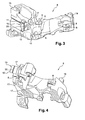
- the support piece 6 has a complex geometry dictated by the topography of the elements which surround it and on which it comes to fit together, namely the metering device 3, a part of the distributor 2 and a vertical wall 7 of the engine 1.
- the piece 6 has three disc-shaped protuberances 8, each having a central bore 9, said protuberances 8 constituting part of the anchoring elements of the dispenser 3 on said piece 6.
- Said piece 6 has at one of its ends a protuberance 19 , intended to fix the style cover, which is a flat piece of engine cover, intended to camouflage some unsightly parts of the engine 1.
- the support part 6 also comprises another protrusion 10, traversed by a flattened channel 11 of rectangular section , said channel 11 opening on a flat face 12 of said protuberance 10 via a longitudinal slot 20 whose length is identical to that of the channel 11.
- this protrusion 10 serves to support the oil filling plug 13, intended to supply the oil sump, by means of a tube 14.
- the support piece is provided with a boss 15 having a predetermined geometry for attaching the fuel conduit 16.
- the support piece 6 has a multiplicity of openwork support surfaces 17 provided with holding tabs 21 whose locations are designed to fix, by means of said tabs 21 and in several places, electrical conduits 18.
- All the anchoring points intended to fix the various objects 13, 16, 18 described above are positioned on the support part 6, so that said objects 13, 16, 18 do not interfere with each other and do not overlap in a haphazard way.
Landscapes
- Engineering & Computer Science (AREA)
- Chemical & Material Sciences (AREA)
- Combustion & Propulsion (AREA)
- Mechanical Engineering (AREA)
- General Engineering & Computer Science (AREA)
- Supports For Pipes And Cables (AREA)
- Cooling, Air Intake And Gas Exhaust, And Fuel Tank Arrangements In Propulsion Units (AREA)
Abstract
Description
- Le domaine technique de l'invention est celui des dispositifs de calage d'un répartiteur d'admission d'air sur un moteur à combustion interne d'un véhicule automobile, dans le cas où le répartiteur est situé en surplomb du moteur et est prolongé par un doseur d'air placé à distance dudit moteur. Pour être plus précis, il s'agit d'un dispositif de calage effectué par l'intermédiaire du doseur d'air. Pour ce type de configuration, le doseur d'air, qui est doté d'un certain poids, et qui est placé à une extrémité du répartiteur, augmente l'effet bras de levier du répartiteur, et risque, à la moindre sollicitation, de le casser. Les dispositifs de calage selon l'invention, mettent en oeuvre des moyens mécaniques pour permettre d'atténuer l'influence du doseur sur le répartiteur, afin de limiter les probabilités de cassure, lesdits moyens étant ensuite aménagés pour occuper d'autres fonctions, et en particulier, pour servir de relais de fixation à des conduits d'acheminements de flux énergétiques et à d'autres pièces situées sous le capot du véhicule.
- Les caractéristiques d'implantation des doseurs d'air sous le capot d'un véhicule automobile ont déjà fait l'objet de plusieurs brevets. On peut, par exemple, citer le brevet
FR 2380428 - Les dispositifs de calage du répartiteur d'admission d'air par l'intermédiaire du doseur d'air selon l'invention, sont parfaitement adaptés aux exigences de poids et d'encombrement réduits, requises pour les objets destinés à être embarqués sur un véhicule automobile. En effet, dispositifs de calage selon l'invention font intervenir une pièce en matériau léger, ayant originellement une fonction bien identifiée, ladite pièce étant aménagée, sans surcroît de matière ni augmentation de volume, pour occuper d'autres fonctions. De façon plus générale, les dispositifs de calage selon l'invention tendent à concentrer certaines fonctions sur des pièces légères, occupant les rares espaces restreints, laissés disponibles sous le capot du véhicule.
- La présente invention a pour objet un dispositif de calage d'un répartiteur d'admission d'air sur un moteur à combustion interne d'un véhicule automobile, le répartiteur étant situé en surplomb du moteur et étant prolongé par un doseur d'air placé à distance dudit moteur. La principale caractéristique d'un dispositif de calage selon l'invention est qu'il comprend une pièce de soutien en matière plastique, insérée entre le répartiteur et le moteur, de façon à supporter le doseur et à réduire les contraintes exercées par ledit doseur sur ledit répartiteur. En effet, pour certaines catégories de moteur, le répartiteur est fixé sur ledit moteur, de sorte que son centre de gravité se retrouve à l'extérieur de sa surface de sustentation. Comme le doseur est suspendu au bout du répartiteur et qu'il possède un poids non négligeable, il accentue les contraintes sur ledit répartiteur au niveau de son point de fixation sur le moteur, et peut ainsi engendrer sa rupture. Une pièce tampon en matière plastique est intercalée entre le répartiteur et le moteur, afin de soutenir ledit répartiteur, en atténuant notamment l'influence du poids du doseur d'air sur le répartiteur.
- Avantageusement, le répartiteur d'admission d'air possède une entrée d'air située en dessous d'une sortie d'air, ledit répartiteur étant solidarisé audit moteur au niveau de ladite sortie, et le doseur d'air est placé au niveau de ladite entrée. Cette configuration doit être interprétée par rapport à la hauteur du moteur, qui est sa dimension prise par rapport à un axe vertical lorsqu'il est positionné sous le capot du véhicule. Le répartiteur se retrouve donc en position inclinée, son point haut correspondant à la sortie d'air, c'est-à-dire à son point de fixation sur le moteur, et son point bas correspondant à l'entrée d'air où est fixé le doseur d'air. De cette manière, le plan dans lequel est situé le répartiteur fait un angle aigu avec la face verticale du moteur se trouvant la plus proche dudit répartiteur.
- De façon préférentielle, la pièce de soutien vient en butée à la fois contre le moteur et contre le doseur d'air. L'interposition de cette pièce entre le moteur et le répartiteur, empêche l'extrémité libre du répartiteur, où est notamment située l'entrée d'air et où est fixé le doseur, de se rapprocher du moteur.
- De façon avantageuse, la pièce de soutien vient en butée à la fois contre le moteur et contre le doseur d'air. Il s'agit de la position d'implantation optimisée de la pièce, pour favoriser son rôle de soutien du répartiteur vis-à-vis du moteur.
- Préférentiellement, le doseur est relié à la pièce de soutien, au moyen de plusieurs points d'ancrage, matérialisés au niveau de ladite pièce, par des protubérances discoïdales munies d'un alésage central. En effet, afin de maintenir la pièce de soutien dans la même position optimisée, il est nécessaire de la fixer solidement au doseur, pour éviter toute dérive de positionnement. Les points d'ancrage peuvent revêtir toute forme, dès lors qu'ils ne sont pas trop nombreux ni trop encombrants.
- Avantageusement, la pièce de soutien possède sur sa surface, à des endroits bien identifiés, des empreintes dont les caractéristiques géométriques et structurelles ont été définies pour recevoir des éléments de fixations d'au moins un conduit de flux énergétiques. La pièce de soutien initialement prévue pour soutenir le répartiteur, est ainsi aménagée simplement, sans accroître son volume d'encombrement, pour servir de pièce relais de fixation à divers conduits énergétiques. En effet, les conduits énergétiques sous le capot d'un véhicule automobile, sont nombreux et de longueur importante, et il demeure toujours compliqué de trouver des surfaces solides disponibles, sur lesquelles fixer ces conduits, en raison d'une optimisation permanente des volumes laissés vacants autour du moteur. La pièce de soutien devient ainsi multifonctionnelle.
- De façon préférentielle, les empreintes peuvent être représentées par des protubérances, des évidements, des trous ou des pattes de fixation. L'un des objectifs visés par ces empreintes, outre le fait qu'elles vont servir à recevoir des éléments de fixation de conduits énergétiques, est de contribuer à maintenir constant le volume de la pièce de soutien. Elles sont donc généralement peu marquées et s'appuient sur des reliefs de la dite pièce déjà existants. Leur forme n'est pas limitative.
- De façon avantageuse, les empreintes servent à fixer en même temps, des conduits relatifs au transport d'huile, d'énergie électrique, et de carburant. La surface et le volume de la pièce de soutien sont ainsi rentabilisés au maximum, en servant de relais de fixation à tous les conduits énergétique croisant leur chemin avec ladite pièce. A priori, il n'y a pas d'incompatibilité sur le fait que les conduits se croisent au niveau de ladite pièce, ni même se touchent entre eux. Cette pièce présente ainsi de limitation ou de restriction.
- Préférentiellement, la pièce possède également des empreintes pour fixer le cache de style.
- De façon avantageuse, la pièce de soutien est réalisée par moulage. Ce procédé de fabrication offre une multiplicité de possibilités quant à la forme, la géométrie et le lieu de d'emplacement desdites empreintes sur ladite pièce.
- De façon préférentielle, la pièce de soutien est réalisée dans une matière plastique usuelle, ayant des propriétés de tenue à la température.
- Outre le fait d'assurer leur fonction originelle de calage, les dispositifs selon l'invention présentent l'avantage de cumuler d'autres fonctions, plutôt passives, grâce à l'aménagement d'une pièce facile à fabriquer, légère et peu coûteuse. Ils présentent également l'avantage de contribuer à stabiliser l'installation de diverses pièces sous le capot du véhicule, comme, par exemple, des conduits de flux énergétiques, en concentrant les points de fixation.
- On donne ci-après une description détaillée d'un mode de réalisation préféré d'un dispositif de calage selon l'invention en se référant aux
figures 1 à 8 . - La
figure 1 est une vue de coté d'un moteur selon l'invention, montrant le répartiteur en porte à faux ainsi que la pièce de soutien. - La
figure 2 est une vue de face du moteur de lafigure1 . - La
figure 3 est une vue en perspective de la pièce de soutien appartenant à un dispositif selon l'invention. - La
figure 4 est une vue en perspective de la pièce de soutien de lafigure 3 , mais sous un angle différent. - La
figure 5 est une vue en perspective d'une partie de la pièce de soutien montrant la fixation du tuyau de carburant. - La
figure 6 est une vue en perspective d'une partie de la pièce de soutien montrant la fixation du remplissage d'huile. - La
figure 7 est une vue en perspective d'une partie de la pièce de soutien montrant une première fixation d'un conduit électrique. - La
figure 8 est une vue en perspective d'une partie de la pièce de soutien montrant une deuxième fixation du conduit électrique de lafigure 7 . - En se référant aux
figures 1 et 2 , un dispositif de calage selon l'invention est particulièrement adapté à une configuration pour laquelle un répartiteur 2 est à la fois relié à un moteur 1 à combustion interne, et à un double doseur 3 d'air, dont les fonctions sont de doser la pression de l'air frais en créant une perte de charge supplémentaire du coté de l'admission d'air, d'augmenter le taux d'EGR en vannant l'admission, et de court-circuiter le refroidisseur d'air suralimenté pour admettre de l'air plus chaud. Pour cette cofiguration, le répartiteur 2 a la forme d'une pièce triangulaire de faible épaisseur, dont la partie évasée 4 correspond à une sortie d'air, et dont la partie resserrée 5 correspond à une entrée d'air, le doseur 3 étant relié au répartiteur 2 en amont de ladite entrée d'air. Lesfigures 1 et 2 , montrent le moteur 1 dans la position selon laquelle il est monté dans le véhicule automobile. De cette manière, l'axe longitudinal dudit moteur 1 correspond à un axe vertical. Le répartiteur 2 est solidarisé au moteur 1 au niveau de sa partie évasée 4, de telle manière que sa partie resserrée 5, correspondant à l'entrée d'air, se retrouve en dessous de ladite partie évasée 4. Le répartiteur 2 se retrouve en position inclinée et en surplomb du moteur 1, et le doseur 3, qui est situé dans le prolongement de la partie resserrée 5 du répartiteur 2, exerce à cause de son poids, un effort sur ledit répartiteur 2 au niveau de son point de fixation sur le moteur 1 correspondant à sa partie évasée 4. Afin de diminuer cet effet de porte à faux, le dispositif de calage selon l'invention, met en oeuvre une pièce de soutien 6 en plastique, qui est insérée entre le moteur 1 et le répartiteur 2, ladite pièce 6 venant en butée à la fois contre le doseur 3 et contre l'une 7 des faces verticales dudit moteur 1. Autrement dit, la pièce 6 de soutien renforce la stabilité d'implantation du répartiteur 2, en agissant en partie, sur le doseur 3. Cette pièce 6 sert donc à soutenir le répartiteur 2 afin de lui empêcher d'effectuer de grands déplacements et donc de maintenir sa tenue mécanique. La pièce 6 de soutien en plastique a des modes vibratoires d'une fréquence de 60 Hz pour assurer son intégrité. - En se référant aux
figures 3 et 4 , la pièce 6 de soutien a une géométrie complexe dictée par la topographie des éléments qui l'entourent et sur lesquels elle vient s'emboîter, à savoir le doseur 3, une partie du répartiteur 2 et une paroi verticale 7 du moteur 1. En se référant à lafigure 3 , la pièce 6 possède trois protubérances 8 discoïdales, présentant chacune un alésage central 9, lesdites protubérances 8 constituant une partie des éléments d'ancrage du doseur 3 sur ladite pièce 6. Ladite pièce 6 comporte à l'une de ses extrémités une protubérance 19, destinée à fixer le cache de style, qui est une pièce plane d'habillage moteur, destinée à camoufler certaines parties disgracieuses du moteur 1. La pièce de soutien 6 comprend également une autre protubérance 10, traversée par un canal 11 aplati de section rectangulaire, ledit canal 11 débouchant sur une face plane 12 de ladite protubérance 10 par l'intermédiaire d'une fente 20 longitudinale dont la longueur est identique à celle du canal 11. En se référant à lafigure 6 , cette protubérance 10 sert à supporter le bouchon 13 de remplissage d'huile, destiné à permettre d'approvisionner le carter d'huile, au moyen d'une tubulure 14. En se référant auxfigures 3,4 et5 , la pièce de soutien est dotée d'une bosse 15 ayant une géométrie prédéterminée pour fixer le conduit 16 de carburant. Enfin, en se référant auxfigures 3,4 ,5 et 6 , la pièce de soutien 6 dispose d'une multiplicité de surfaces d'appui 17 ajourées et munies de pattes 21 de maintien, dont les emplacements sont étudiés pour fixer, au moyen desdites pattes 21 et en plusieurs endroits, des conduits électriques 18. - Tous les points d'ancrages destinés à fixer les différents objets 13,16,18 décrits ci-avant, sont positionnés sur la pièce de soutien 6, de manière à ce que lesdits objets 13,16,18 n'interférent pas entre eux et ne se chevauchent pas de façon désordonnée.
Claims (8)
- Ensemble formé par un moteur (1) à combustion interne d'un véhicule automobile associé à un répartiteur (2) d'admission d'air étant situé en surplomb du moteur (1) et étant prolongé par un doseur (3) d'air placé à distance dudit moteur (1), une pièce de soutien (6) étant insérée entre le répartiteur (2) et le moteur (1), de façon à supporter le doseur (3) et à réduire les contraintes exercées par ledit doseur (3) sur ledit répartiteur (2), caractérisé en ce que la pièce de soutien (6) est en matière plastique et possède sur sa surface, à des endroits bien identifiés, des empreintes (10,15,17,21) dont les caractéristiques géométriques et structurelles ont été définies pour recevoir des éléments de fixations des conduits relatifs au transport d'huile, d'énergie électrique, et de carburant.
- Ensemble selon la revendication 1, caractérisé en ce que le répartiteur (2) d'admission d'air possède une entrée (5) d'air située en dessous d'une sortie (4) d'air, ledit répartiteur (2) étant solidarisé audit moteur (1) au niveau de ladite sortie (4), et le doseur (3) d'air est placé au niveau de ladite entrée (5).
- Ensemble selon la revendication 2, caractérisé en ce que la pièce (6) de soutien vient en butée à la fois contre le moteur (1) et contre le doseur d'air (3).
- Ensemble selon la revendication 3, caractérisé en ce que le doseur (3) est relié à la pièce (6) de soutien, au moyen de plusieurs points d'ancrage, matérialisés au niveau de ladite pièce (6), par des protubérances discoïdales (8) munies d'un alésage central (9).
- Ensemble selon l'une quelconque des revendications précédentes, caractérisé en ce que les empreintes (10,15,17,21) peuvent être représentées par des protubérances, des évidements, des trous ou des pattes de fixation.
- Ensemble selon l'une quelconque des revendications précédentes, caractérisé en ce que la pièce (6) de soutien possède également des empreintes (19) pour fixer le cache de style.
- Ensemble selon l'une quelconque des revendications précédentes, caractérisé en ce que la pièce (6) de soutien est réalisée par moulage.
- Ensemble selon la revendication 7, caractérisé en ce que la pièce (6) de soutien est réalisée dans une matière plastique usuelle, ayant des propriétés de tenue à la température.
Applications Claiming Priority (1)
| Application Number | Priority Date | Filing Date | Title |
|---|---|---|---|
| FR0752529A FR2911093B1 (fr) | 2007-01-04 | 2007-01-04 | Dispositif de calage d'un repartiteur d'admission d'air sur un moteur. |
Publications (2)
| Publication Number | Publication Date |
|---|---|
| EP1942272A1 true EP1942272A1 (fr) | 2008-07-09 |
| EP1942272B1 EP1942272B1 (fr) | 2013-04-17 |
Family
ID=38353851
Family Applications (1)
| Application Number | Title | Priority Date | Filing Date |
|---|---|---|---|
| EP20070150172 Not-in-force EP1942272B1 (fr) | 2007-01-04 | 2007-12-19 | Dispositif de calage d'un répartiteur d'admission d'air sur un moteur |
Country Status (2)
| Country | Link |
|---|---|
| EP (1) | EP1942272B1 (fr) |
| FR (1) | FR2911093B1 (fr) |
Citations (6)
| Publication number | Priority date | Publication date | Assignee | Title |
|---|---|---|---|---|
| FR2380428A1 (fr) | 1977-02-11 | 1978-09-08 | Acf Ind Inc | Appareillage de commande de la richesse du melange brule dans un moteur a combustion interne |
| JPH0565857A (ja) * | 1991-09-05 | 1993-03-19 | Mazda Motor Corp | インテークマニホールドの支持構造 |
| DE19548024C1 (de) * | 1995-12-21 | 1996-12-05 | Daimler Benz Ag | Vorrichtung zur Befestigung eines Saugmoduls an einer Brennkraftmaschine |
| US5887560A (en) * | 1997-07-31 | 1999-03-30 | Suzuki Motor Corporation | Support structure for intake system of internal combustion engine |
| JP2003201928A (ja) * | 2001-12-28 | 2003-07-18 | Suzuki Motor Corp | エンジンの吸気系支持構造 |
| FR2848603A1 (fr) * | 2002-12-12 | 2004-06-18 | Renault Sa | Attache pour fixer temporairement un conduit flexible sur un moteur de vehicule automobile |
-
2007
- 2007-01-04 FR FR0752529A patent/FR2911093B1/fr not_active Expired - Fee Related
- 2007-12-19 EP EP20070150172 patent/EP1942272B1/fr not_active Not-in-force
Patent Citations (6)
| Publication number | Priority date | Publication date | Assignee | Title |
|---|---|---|---|---|
| FR2380428A1 (fr) | 1977-02-11 | 1978-09-08 | Acf Ind Inc | Appareillage de commande de la richesse du melange brule dans un moteur a combustion interne |
| JPH0565857A (ja) * | 1991-09-05 | 1993-03-19 | Mazda Motor Corp | インテークマニホールドの支持構造 |
| DE19548024C1 (de) * | 1995-12-21 | 1996-12-05 | Daimler Benz Ag | Vorrichtung zur Befestigung eines Saugmoduls an einer Brennkraftmaschine |
| US5887560A (en) * | 1997-07-31 | 1999-03-30 | Suzuki Motor Corporation | Support structure for intake system of internal combustion engine |
| JP2003201928A (ja) * | 2001-12-28 | 2003-07-18 | Suzuki Motor Corp | エンジンの吸気系支持構造 |
| FR2848603A1 (fr) * | 2002-12-12 | 2004-06-18 | Renault Sa | Attache pour fixer temporairement un conduit flexible sur un moteur de vehicule automobile |
Also Published As
| Publication number | Publication date |
|---|---|
| FR2911093B1 (fr) | 2009-10-09 |
| FR2911093A1 (fr) | 2008-07-11 |
| EP1942272B1 (fr) | 2013-04-17 |
Similar Documents
| Publication | Publication Date | Title |
|---|---|---|
| EP1983619B1 (fr) | Embase de connexion coaxiale 7-16 | |
| FR2935457A1 (fr) | Connecteur rapide a stabilisation laterale | |
| FR2691298A1 (fr) | Boîtier pour appareillages électriques et accessoires pour l'établissement de réseaux. | |
| EP2088303B1 (fr) | Procédé de réalisation d'une plaque support pour corps de clapets et plaque support | |
| FR3084709A1 (fr) | Accouplement en rotation | |
| FR2597548A1 (fr) | Dispositif de logement pour unite centrale de traitement electronique de moteur a combustion interne | |
| EP4304901A1 (fr) | Dispositif de support du chargeur de batterie des vehicules automobiles | |
| EP1942272B1 (fr) | Dispositif de calage d'un répartiteur d'admission d'air sur un moteur | |
| FR3038000A1 (fr) | Reservoir a uree avec dispositif de chauffage. | |
| FR3031158A1 (fr) | Enveloppe de protection et de lestage d'un conduit, notamment en milieu sous-marin, et dispositif comprenant au moins deux telles enveloppes solidarisees entre elles. | |
| CH685315A5 (fr) | Boîtier pour appareillages électriques. | |
| EP3585996B1 (fr) | Dispositif pour la réduction de la consommation en carburant d'un moteur | |
| CA2921905C (fr) | Structure de carter interposee entre le moteur et la nacelle a platine a vis | |
| FR2956704A1 (fr) | Vehicule comportant un dispositif de fixation permettant de solidariser deux elements sur un unique point de fixation d'un support et dispositif de fixation correspondant | |
| WO2015082401A1 (fr) | Conduit de liaison reliant un dispositif thermique de vehicule automobile au tablier du vehicule | |
| EP2208010B1 (fr) | Echangeur de chaleur pour fluides haute et basse température | |
| EP4163449A1 (fr) | Mur a coffrage integre avec moyen de liaison deployable et kit de liaison pour un tel mur a coffrage integre | |
| FR2800862A1 (fr) | Radiateur de fluide de refroidissement comportant un reservoir de compensation | |
| WO2018055289A1 (fr) | Elément de carrosserie mobile avec alliage à mémoire de forme | |
| FR2808854A1 (fr) | Support antivibratoire, et vehicule comportant un tel support | |
| FR2971565A1 (fr) | Systeme de fixation reglable formant entretoise. | |
| EP3519755B1 (fr) | Boîte collectrice de fluide pour échangeur de chaleur, échangeur de chaleur associé | |
| FR2792975A1 (fr) | Collier articule | |
| EP3358090A1 (fr) | Réservoir modulable | |
| FR2931544A1 (fr) | Module d'echange de chaleur comprenant au moins deux echangeurs de chaleur parcourus par un meme fluide caloporteur. |
Legal Events
| Date | Code | Title | Description |
|---|---|---|---|
| PUAI | Public reference made under article 153(3) epc to a published international application that has entered the european phase |
Free format text: ORIGINAL CODE: 0009012 |
|
| AK | Designated contracting states |
Kind code of ref document: A1 Designated state(s): AT BE BG CH CY CZ DE DK EE ES FI FR GB GR HU IE IS IT LI LT LU LV MC MT NL PL PT RO SE SI SK TR |
|
| AX | Request for extension of the european patent |
Extension state: AL BA HR MK RS |
|
| 17P | Request for examination filed |
Effective date: 20081204 |
|
| 17Q | First examination report despatched |
Effective date: 20090112 |
|
| AKX | Designation fees paid |
Designated state(s): AT BE BG CH CY CZ DE DK EE ES FI FR GB GR HU IE IS IT LI LT LU LV MC MT NL PL PT RO SE SI SK TR |
|
| GRAP | Despatch of communication of intention to grant a patent |
Free format text: ORIGINAL CODE: EPIDOSNIGR1 |
|
| RIN1 | Information on inventor provided before grant (corrected) |
Inventor name: RENAULT, CYRIL Inventor name: MARION, THIERRY Inventor name: MASSIEUX, MICHAEL |
|
| GRAS | Grant fee paid |
Free format text: ORIGINAL CODE: EPIDOSNIGR3 |
|
| GRAA | (expected) grant |
Free format text: ORIGINAL CODE: 0009210 |
|
| AK | Designated contracting states |
Kind code of ref document: B1 Designated state(s): AT BE BG CH CY CZ DE DK EE ES FI FR GB GR HU IE IS IT LI LT LU LV MC MT NL PL PT RO SE SI SK TR |
|
| REG | Reference to a national code |
Ref country code: GB Ref legal event code: FG4D Free format text: NOT ENGLISH |
|
| REG | Reference to a national code |
Ref country code: CH Ref legal event code: EP |
|
| REG | Reference to a national code |
Ref country code: IE Ref legal event code: FG4D Free format text: LANGUAGE OF EP DOCUMENT: FRENCH |
|
| REG | Reference to a national code |
Ref country code: AT Ref legal event code: REF Ref document number: 607450 Country of ref document: AT Kind code of ref document: T Effective date: 20130515 |
|
| REG | Reference to a national code |
Ref country code: DE Ref legal event code: R096 Ref document number: 602007029797 Country of ref document: DE Effective date: 20130613 |
|
| REG | Reference to a national code |
Ref country code: AT Ref legal event code: MK05 Ref document number: 607450 Country of ref document: AT Kind code of ref document: T Effective date: 20130417 |
|
| REG | Reference to a national code |
Ref country code: LT Ref legal event code: MG4D |
|
| REG | Reference to a national code |
Ref country code: NL Ref legal event code: VDEP Effective date: 20130417 |
|
| PG25 | Lapsed in a contracting state [announced via postgrant information from national office to epo] |
Ref country code: GR Free format text: LAPSE BECAUSE OF FAILURE TO SUBMIT A TRANSLATION OF THE DESCRIPTION OR TO PAY THE FEE WITHIN THE PRESCRIBED TIME-LIMIT Effective date: 20130718 Ref country code: SE Free format text: LAPSE BECAUSE OF FAILURE TO SUBMIT A TRANSLATION OF THE DESCRIPTION OR TO PAY THE FEE WITHIN THE PRESCRIBED TIME-LIMIT Effective date: 20130417 Ref country code: IS Free format text: LAPSE BECAUSE OF FAILURE TO SUBMIT A TRANSLATION OF THE DESCRIPTION OR TO PAY THE FEE WITHIN THE PRESCRIBED TIME-LIMIT Effective date: 20130817 Ref country code: ES Free format text: LAPSE BECAUSE OF FAILURE TO SUBMIT A TRANSLATION OF THE DESCRIPTION OR TO PAY THE FEE WITHIN THE PRESCRIBED TIME-LIMIT Effective date: 20130728 Ref country code: PT Free format text: LAPSE BECAUSE OF FAILURE TO SUBMIT A TRANSLATION OF THE DESCRIPTION OR TO PAY THE FEE WITHIN THE PRESCRIBED TIME-LIMIT Effective date: 20130819 Ref country code: AT Free format text: LAPSE BECAUSE OF FAILURE TO SUBMIT A TRANSLATION OF THE DESCRIPTION OR TO PAY THE FEE WITHIN THE PRESCRIBED TIME-LIMIT Effective date: 20130417 Ref country code: SI Free format text: LAPSE BECAUSE OF FAILURE TO SUBMIT A TRANSLATION OF THE DESCRIPTION OR TO PAY THE FEE WITHIN THE PRESCRIBED TIME-LIMIT Effective date: 20130417 Ref country code: LT Free format text: LAPSE BECAUSE OF FAILURE TO SUBMIT A TRANSLATION OF THE DESCRIPTION OR TO PAY THE FEE WITHIN THE PRESCRIBED TIME-LIMIT Effective date: 20130417 Ref country code: FI Free format text: LAPSE BECAUSE OF FAILURE TO SUBMIT A TRANSLATION OF THE DESCRIPTION OR TO PAY THE FEE WITHIN THE PRESCRIBED TIME-LIMIT Effective date: 20130417 |
|
| PG25 | Lapsed in a contracting state [announced via postgrant information from national office to epo] |
Ref country code: CY Free format text: LAPSE BECAUSE OF FAILURE TO SUBMIT A TRANSLATION OF THE DESCRIPTION OR TO PAY THE FEE WITHIN THE PRESCRIBED TIME-LIMIT Effective date: 20130417 Ref country code: PL Free format text: LAPSE BECAUSE OF FAILURE TO SUBMIT A TRANSLATION OF THE DESCRIPTION OR TO PAY THE FEE WITHIN THE PRESCRIBED TIME-LIMIT Effective date: 20130417 Ref country code: LV Free format text: LAPSE BECAUSE OF FAILURE TO SUBMIT A TRANSLATION OF THE DESCRIPTION OR TO PAY THE FEE WITHIN THE PRESCRIBED TIME-LIMIT Effective date: 20130417 Ref country code: BG Free format text: LAPSE BECAUSE OF FAILURE TO SUBMIT A TRANSLATION OF THE DESCRIPTION OR TO PAY THE FEE WITHIN THE PRESCRIBED TIME-LIMIT Effective date: 20130717 |
|
| REG | Reference to a national code |
Ref country code: GB Ref legal event code: 746 Effective date: 20131108 |
|
| PG25 | Lapsed in a contracting state [announced via postgrant information from national office to epo] |
Ref country code: EE Free format text: LAPSE BECAUSE OF FAILURE TO SUBMIT A TRANSLATION OF THE DESCRIPTION OR TO PAY THE FEE WITHIN THE PRESCRIBED TIME-LIMIT Effective date: 20130417 Ref country code: DK Free format text: LAPSE BECAUSE OF FAILURE TO SUBMIT A TRANSLATION OF THE DESCRIPTION OR TO PAY THE FEE WITHIN THE PRESCRIBED TIME-LIMIT Effective date: 20130417 Ref country code: SK Free format text: LAPSE BECAUSE OF FAILURE TO SUBMIT A TRANSLATION OF THE DESCRIPTION OR TO PAY THE FEE WITHIN THE PRESCRIBED TIME-LIMIT Effective date: 20130417 Ref country code: CZ Free format text: LAPSE BECAUSE OF FAILURE TO SUBMIT A TRANSLATION OF THE DESCRIPTION OR TO PAY THE FEE WITHIN THE PRESCRIBED TIME-LIMIT Effective date: 20130417 |
|
| PLBE | No opposition filed within time limit |
Free format text: ORIGINAL CODE: 0009261 |
|
| STAA | Information on the status of an ep patent application or granted ep patent |
Free format text: STATUS: NO OPPOSITION FILED WITHIN TIME LIMIT |
|
| PG25 | Lapsed in a contracting state [announced via postgrant information from national office to epo] |
Ref country code: IT Free format text: LAPSE BECAUSE OF FAILURE TO SUBMIT A TRANSLATION OF THE DESCRIPTION OR TO PAY THE FEE WITHIN THE PRESCRIBED TIME-LIMIT Effective date: 20130417 Ref country code: NL Free format text: LAPSE BECAUSE OF FAILURE TO SUBMIT A TRANSLATION OF THE DESCRIPTION OR TO PAY THE FEE WITHIN THE PRESCRIBED TIME-LIMIT Effective date: 20130417 Ref country code: RO Free format text: LAPSE BECAUSE OF FAILURE TO SUBMIT A TRANSLATION OF THE DESCRIPTION OR TO PAY THE FEE WITHIN THE PRESCRIBED TIME-LIMIT Effective date: 20130417 |
|
| 26N | No opposition filed |
Effective date: 20140120 |
|
| REG | Reference to a national code |
Ref country code: DE Ref legal event code: R097 Ref document number: 602007029797 Country of ref document: DE Effective date: 20140120 |
|
| BERE | Be: lapsed |
Owner name: PEUGEOT CITROEN AUTOMOBILES S.A. Effective date: 20131231 |
|
| REG | Reference to a national code |
Ref country code: CH Ref legal event code: PL |
|
| PG25 | Lapsed in a contracting state [announced via postgrant information from national office to epo] |
Ref country code: LU Free format text: LAPSE BECAUSE OF FAILURE TO SUBMIT A TRANSLATION OF THE DESCRIPTION OR TO PAY THE FEE WITHIN THE PRESCRIBED TIME-LIMIT Effective date: 20131219 Ref country code: MC Free format text: LAPSE BECAUSE OF FAILURE TO SUBMIT A TRANSLATION OF THE DESCRIPTION OR TO PAY THE FEE WITHIN THE PRESCRIBED TIME-LIMIT Effective date: 20130417 |
|
| REG | Reference to a national code |
Ref country code: IE Ref legal event code: MM4A |
|
| PG25 | Lapsed in a contracting state [announced via postgrant information from national office to epo] |
Ref country code: IE Free format text: LAPSE BECAUSE OF NON-PAYMENT OF DUE FEES Effective date: 20131219 Ref country code: LI Free format text: LAPSE BECAUSE OF NON-PAYMENT OF DUE FEES Effective date: 20131231 Ref country code: BE Free format text: LAPSE BECAUSE OF NON-PAYMENT OF DUE FEES Effective date: 20131231 Ref country code: CH Free format text: LAPSE BECAUSE OF NON-PAYMENT OF DUE FEES Effective date: 20131231 |
|
| REG | Reference to a national code |
Ref country code: DE Ref legal event code: R084 Ref document number: 602007029797 Country of ref document: DE |
|
| REG | Reference to a national code |
Ref country code: DE Ref legal event code: R084 Ref document number: 602007029797 Country of ref document: DE Effective date: 20150307 |
|
| PG25 | Lapsed in a contracting state [announced via postgrant information from national office to epo] |
Ref country code: TR Free format text: LAPSE BECAUSE OF FAILURE TO SUBMIT A TRANSLATION OF THE DESCRIPTION OR TO PAY THE FEE WITHIN THE PRESCRIBED TIME-LIMIT Effective date: 20130417 |
|
| PG25 | Lapsed in a contracting state [announced via postgrant information from national office to epo] |
Ref country code: HU Free format text: LAPSE BECAUSE OF FAILURE TO SUBMIT A TRANSLATION OF THE DESCRIPTION OR TO PAY THE FEE WITHIN THE PRESCRIBED TIME-LIMIT; INVALID AB INITIO Effective date: 20071219 |
|
| PG25 | Lapsed in a contracting state [announced via postgrant information from national office to epo] |
Ref country code: MT Free format text: LAPSE BECAUSE OF FAILURE TO SUBMIT A TRANSLATION OF THE DESCRIPTION OR TO PAY THE FEE WITHIN THE PRESCRIBED TIME-LIMIT Effective date: 20130417 |
|
| REG | Reference to a national code |
Ref country code: FR Ref legal event code: PLFP Year of fee payment: 9 |
|
| REG | Reference to a national code |
Ref country code: FR Ref legal event code: PLFP Year of fee payment: 10 |
|
| REG | Reference to a national code |
Ref country code: FR Ref legal event code: PLFP Year of fee payment: 11 |
|
| REG | Reference to a national code |
Ref country code: FR Ref legal event code: CA Effective date: 20180312 Ref country code: FR Ref legal event code: CD Owner name: PEUGEOT CITROEN AUTOMOBILES SA, FR Effective date: 20180312 |
|
| PGFP | Annual fee paid to national office [announced via postgrant information from national office to epo] |
Ref country code: DE Payment date: 20211117 Year of fee payment: 15 |
|
| PGFP | Annual fee paid to national office [announced via postgrant information from national office to epo] |
Ref country code: GB Payment date: 20221116 Year of fee payment: 16 Ref country code: FR Payment date: 20221123 Year of fee payment: 16 |
|
| REG | Reference to a national code |
Ref country code: DE Ref legal event code: R119 Ref document number: 602007029797 Country of ref document: DE |
|
| PG25 | Lapsed in a contracting state [announced via postgrant information from national office to epo] |
Ref country code: DE Free format text: LAPSE BECAUSE OF NON-PAYMENT OF DUE FEES Effective date: 20230701 |
|
| GBPC | Gb: european patent ceased through non-payment of renewal fee |
Effective date: 20231219 |
|
| PG25 | Lapsed in a contracting state [announced via postgrant information from national office to epo] |
Ref country code: GB Free format text: LAPSE BECAUSE OF NON-PAYMENT OF DUE FEES Effective date: 20231219 |
|
| PG25 | Lapsed in a contracting state [announced via postgrant information from national office to epo] |
Ref country code: FR Free format text: LAPSE BECAUSE OF NON-PAYMENT OF DUE FEES Effective date: 20231231 |
|
| PG25 | Lapsed in a contracting state [announced via postgrant information from national office to epo] |
Ref country code: GB Free format text: LAPSE BECAUSE OF NON-PAYMENT OF DUE FEES Effective date: 20231219 Ref country code: FR Free format text: LAPSE BECAUSE OF NON-PAYMENT OF DUE FEES Effective date: 20231231 |