EP1942235A2 - Verkleidungssysteme - Google Patents
Verkleidungssysteme Download PDFInfo
- Publication number
- EP1942235A2 EP1942235A2 EP08000068A EP08000068A EP1942235A2 EP 1942235 A2 EP1942235 A2 EP 1942235A2 EP 08000068 A EP08000068 A EP 08000068A EP 08000068 A EP08000068 A EP 08000068A EP 1942235 A2 EP1942235 A2 EP 1942235A2
- Authority
- EP
- European Patent Office
- Prior art keywords
- formation
- channel section
- brackets
- support bar
- bracket
- Prior art date
- Legal status (The legal status is an assumption and is not a legal conclusion. Google has not performed a legal analysis and makes no representation as to the accuracy of the status listed.)
- Withdrawn
Links
- 238000005253 cladding Methods 0.000 title claims abstract description 54
- 230000015572 biosynthetic process Effects 0.000 claims abstract description 118
- 238000005755 formation reaction Methods 0.000 claims abstract description 118
- 229910000831 Steel Inorganic materials 0.000 claims abstract description 4
- 239000010959 steel Substances 0.000 claims abstract description 4
- 239000004033 plastic Substances 0.000 claims description 11
- 229920003023 plastic Polymers 0.000 claims description 11
- 238000001125 extrusion Methods 0.000 claims description 7
- 239000004411 aluminium Substances 0.000 claims description 5
- 229910052782 aluminium Inorganic materials 0.000 claims description 5
- XAGFODPZIPBFFR-UHFFFAOYSA-N aluminium Chemical compound [Al] XAGFODPZIPBFFR-UHFFFAOYSA-N 0.000 claims description 5
- 239000010935 stainless steel Substances 0.000 claims description 3
- 229910001220 stainless steel Inorganic materials 0.000 claims description 3
- 229910000838 Al alloy Inorganic materials 0.000 claims description 2
- 238000004080 punching Methods 0.000 claims description 2
- 239000000463 material Substances 0.000 description 10
- 230000004048 modification Effects 0.000 description 6
- 238000012986 modification Methods 0.000 description 6
- 229910052751 metal Inorganic materials 0.000 description 5
- 239000002184 metal Substances 0.000 description 5
- 238000010276 construction Methods 0.000 description 2
- 230000000712 assembly Effects 0.000 description 1
- 238000000429 assembly Methods 0.000 description 1
- 230000004888 barrier function Effects 0.000 description 1
- 230000008602 contraction Effects 0.000 description 1
- 230000007423 decrease Effects 0.000 description 1
- 238000003780 insertion Methods 0.000 description 1
- 230000037431 insertion Effects 0.000 description 1
- 239000012774 insulation material Substances 0.000 description 1
- 238000000034 method Methods 0.000 description 1
- 230000002787 reinforcement Effects 0.000 description 1
Images




Classifications
-
- E—FIXED CONSTRUCTIONS
- E04—BUILDING
- E04D—ROOF COVERINGS; SKY-LIGHTS; GUTTERS; ROOF-WORKING TOOLS
- E04D3/00—Roof covering by making use of flat or curved slabs or stiff sheets
- E04D3/36—Connecting; Fastening
- E04D3/361—Connecting; Fastening by specially-profiled marginal portions of the slabs or sheets
-
- E—FIXED CONSTRUCTIONS
- E04—BUILDING
- E04D—ROOF COVERINGS; SKY-LIGHTS; GUTTERS; ROOF-WORKING TOOLS
- E04D3/00—Roof covering by making use of flat or curved slabs or stiff sheets
- E04D3/36—Connecting; Fastening
- E04D3/361—Connecting; Fastening by specially-profiled marginal portions of the slabs or sheets
- E04D3/362—Connecting; Fastening by specially-profiled marginal portions of the slabs or sheets by locking the edge of one slab or sheet within the profiled marginal portion of the adjacent slab or sheet, e.g. using separate connecting elements
-
- E—FIXED CONSTRUCTIONS
- E04—BUILDING
- E04D—ROOF COVERINGS; SKY-LIGHTS; GUTTERS; ROOF-WORKING TOOLS
- E04D13/00—Special arrangements or devices in connection with roof coverings; Protection against birds; Roof drainage ; Sky-lights
- E04D13/16—Insulating devices or arrangements in so far as the roof covering is concerned, e.g. characterised by the material or composition of the roof insulating material or its integration in the roof structure
- E04D13/1606—Insulation of the roof covering characterised by its integration in the roof structure
- E04D13/1643—Insulation of the roof covering characterised by its integration in the roof structure the roof structure being formed by load bearing corrugated sheets, e.g. profiled sheet metal roofs
- E04D13/165—Double skin roofs
-
- E—FIXED CONSTRUCTIONS
- E04—BUILDING
- E04D—ROOF COVERINGS; SKY-LIGHTS; GUTTERS; ROOF-WORKING TOOLS
- E04D3/00—Roof covering by making use of flat or curved slabs or stiff sheets
- E04D3/36—Connecting; Fastening
- E04D3/3601—Connecting; Fastening of roof covering supported by the roof structure with interposition of a insulating layer
- E04D3/3602—The fastening means comprising elongated profiles installed in or on the insulation layer
-
- E—FIXED CONSTRUCTIONS
- E04—BUILDING
- E04D—ROOF COVERINGS; SKY-LIGHTS; GUTTERS; ROOF-WORKING TOOLS
- E04D3/00—Roof covering by making use of flat or curved slabs or stiff sheets
- E04D3/36—Connecting; Fastening
- E04D3/361—Connecting; Fastening by specially-profiled marginal portions of the slabs or sheets
- E04D2003/3612—Separate fastening elements fixed to the roof structure and comprising plastic parts for avoiding thermal bridges
-
- E—FIXED CONSTRUCTIONS
- E04—BUILDING
- E04D—ROOF COVERINGS; SKY-LIGHTS; GUTTERS; ROOF-WORKING TOOLS
- E04D3/00—Roof covering by making use of flat or curved slabs or stiff sheets
- E04D3/36—Connecting; Fastening
- E04D3/361—Connecting; Fastening by specially-profiled marginal portions of the slabs or sheets
- E04D2003/3615—Separate fastening elements fixed to the roof structure and consisting of parts permitting relative movement to each other, e.g. for thermal expansion
Definitions
- the present invention relates to cladding systems, for example roof or wall cladding systems, including support bars which are mounted by brackets to a support structure, cladding panels being secured to the support bars by means of further brackets.
- Such a prior art support bracket is formed from a single piece of bent galvanised steel sheet and comprises a generally flat body portion 12, and a mounting portion 14 which extends from a first end 12a of the body portion 12 generally perpendicular thereto.
- the mounting portion 14 is provided with a plurality of apertures through which fasteners such as screws or bolts may pass in order to fasten the mounting portion 14 onto a rafter.
- a second end 1 2b of the body portion 1 2 is provided with cut-outs 18 which permit it to engage with flange formations 20 on a channel section roofing bar 16.
- the bracket 12 may be located at an appropriate position on the roofing bar 16 and twisted so that the cut outs 18 engage the flange formations 20 and lock the support bracket 10 in position. Further brackets (not shown) may then be secured to the roofing bar, by suitable fastening means, to support the cladding panels.
- GB-A-2423097 discloses a modified support bracket with formations which slidingly engage flange formations on the roofing bar, so that the bracket formations may be positioned longitudinally of the roofing bar, by sliding them along the bar. This specification also discloses that brackets for supporting the cladding panels may also be slidingly located on the roofing bar.
- Both of the above mentioned cladding systems use a support/roofing bar of channel section, the channel opening towards the support structure, the support brackets between the support bar and support structure extending within the side walls of the channel section and the brackets for supporting the cladding panels being secured to the base of the channel section.
- a cladding system includes a support bar, the support bar being of channel section, having a base and a pair of side walls extending to one side of the base, inwardly extending flange formations extending along the edges of the side walls remote from the base; a plurality of first bracket formations, the first bracket formations having a base formation adapted to be secured to a support structure and a formation, spaced axially of the base formation, for engagement of the channel section, so that the first brackets may be secured to the channel section at longitudinally spaced locations, the first brackets extending away from the base of the channel section to the opposite side as the walls of the channel section; and a plurality of second brackets, each of the second brackets having, a foot formation which engages in the channel section, the foot formation engaging beneath the flange formation on each side of the channel section support bar, to slidingly locate the second bracket in the channel section support bar and an elongate formation of uniform profile spaced axially of the foot formation for
- a series of support bars will normally be mounted in parallel relationship, transverse to the seams between adjacent cladding sheets to be supported by the bars.
- Each support bar is sildingly engaged with formations on a plurality of first brackets which may be pre-secured to a support structures, in aligned, spaced relationship.
- a series of second brackets are then mounted in spaced relationship on the support bar, the second brackets being located in the channel section support bar with the foot formation parallel to the longitudinal axis of the bar and then twisted through 90°, so that the foot formation engages beneath the inwardly directed flange formations on either side of the channel section.
- the second brackets may then be slid longitudinally along the channel, to accurately align the profiles of second brackets located in each of the parallel support bars, so that seams of corresponding section to the profile of the second bracket, which are preformed on the cladding panels, may engage the profiles of several of the aligned second brackets.
- the second brackets in accordance with the present invention may be formed by extrusion, from suitable material, for example metal such as aluminium or a plastics material, the extrusion being cut into lengths equal substantially to the width of the channel section, formations then being formed, which will slidingly engage the flange formations of the support bar.
- suitable material for example metal such as aluminium or a plastics material
- the second brackets are extruded from aluminium or an aluminium alloy, slots being punched in the side edges of the bracket, above the foot formation, for engagement of the flange formations of the support bar.
- the punch die may be adapted to round the end edges of the profile, in order to provide a rounded lead-in edge, which will avoid snagging with the cladding panels as they slide over the profiles, as the roof is constructed and after construction of the roof, to allow for thermal expansion and contraction.
- While the present invention is particularly suitable for roofing structures and is described hereinafter by reference to roof structures, it is also suitable for other cladding systems, for example wall cladding systems.
- Figure 1 shows a roof structure, in which a series of roofing bars 16 are mounted parallel to one another, at spaced intervals down the slope of a roof.
- the roofing bars 16 are supported on rafters or purlins 22, by means of brackets 12, for example as described above, with reference to figure 2 .
- the bars 16 are of channel section, opening towards the rafter or purlin 22, the brackets 12 extending into the channel, formations 18 on the bracket 12 engaging corresponding formations on the bar 16.
- the brackets 12 are provided at spaced locations along the length of the bars 16, across the span of the roof.
- brackets 30 are secured to the upper face of the bars 16, by suitable fastening means, the brackets 30 being located at spaced intervals along the bars 16. Brackets 30 on each of the bars 16 are aligned with brackets 30 on the other bars 16, up the roof. The positioning of the brackets 30 across the roof corresponds to raised seam formations 32 on cladding panels 34. The upper ends of the brackets 30 are provided with profiles 36 which correspond to the profile of the seams 32 on cladding panels 34, so that the cladding panels 34, with performed seams 32, my be drawn down the roof, the seams 34 engaging the profiles 36 of aligned brackets 30.
- the roof may be provided with an inner skin (not shown) made, for example, of corrugated metal sheet, which is secured directly to the rafters or purlins 22, the brackets 12 being secured to the rafters or purlins 22, on top of this inner skin. Insulation material may then be packed between the inner skin and cladding panels 34.
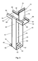
- the brackets 40 which support a roofing bar 60 comprises a body portion 42 of channel section, with a base 44 and side walls 46. At one end of the body portion 42, an extension 48 of the base 44 is bent at right angles to the opposite side of the base 44 to the walls 46 and extensions 50 of the walls 46 are bent inwardly, so that the extensions 48 and 50 form a substantially planar surface, holes 52 being provided in extensions 48 and 50, by which the bracket 40 may be secured to the rafter or purlin 22, by suitable fastening means. Corrugations 54 are provided in extensions 48 and 50 to provide reinforcement and a more secure location of the bracket 40.
- an extension 56 of the base 44 is bent at right angles to the base 44, between the side walls 46.
- the side walls 46 extend axially beyond the bent extension 56, extensions 58 of the side walls 46 being bent at right angles towards one another, so that the extensions 58 extend in a plane parallel to but spaced axially of the extension 56.
- the roofing bar 60 is of channel section having a base 62 and side walls 64 extending to one side of the base 62.
- Flange formations 66 extend inwardly from the free edges of the side walls 64 , a lip formation 68 extending towards the base 62 along the inner edges of the flange formations 66.
- the depth of the bar 60 is equal to the spacing between extensions 56 and 58 of the bracket 40, so that the bar 60 is a sliding fit between extensions 56 and 58, extension 56 engaging the base 44 of the channel section bar 60 and extensions 58 engaging the flange formations 66.
- Brackets 70 have a planar body portion 72. At the lower end, the thickness of the body portion 72 is increased to both sides across the width of the body portion, to form a foot formation 74. A profile 76 extends across the full width of the body portion, along the upper edge thereof. The width of the body portion 72 is substantially equal to the distance between the side walls 64 of the channel section bar 60.
- a pair of slots 78 are provided one on either side of the body portion 72, adjacent the foot formation 74, to provide a clearance for the flange/lip formations 66,68, so that the brackets 70 may be located transversely in the channel section bar 60, the foot formation 74 engaging between the walls 64 of the channel section and the extremities of the foot formation 74 engaging between the base 62 and flange/lip formations 66.68.
- the brackets 70 are thus capable of sliding along the channel section bar 60.
- brackets 70 when locating the brackets 70, they may be positioned in the channel at the appropriate position, the width of the bracket 70 extending along the channel section, and then twisted, so that the flange/lip formations 66,68 engage in the slots 78, and the extremities of the foot formation 74 engage beneath the flange/lip formations 66,68.
- the brackets 70 may then slide along the channel section bar 60, to accurately align the brackets 70 and accommodate any tolerance variations in the width of the cladding panels 34,
- the brackets 70 may conveniently be formed from aluminium or some similar material by extrusion, the brackets 70 being cut to width, from an extruded strip.
- the slots 78 may be formed by punching with a die.
- the die may be arranged to form radiuses 80 on the edges of the profile 76, at both ends. These radiuses 80 allow the seams 32 of the cladding panels 34 to slide over the profiles 76, when constructing the roof, and also to allow for thermal expansion after construction, without snagging.
- Figure 7 shows a boot 90, which may be moulded from plastics material.
- the boot 90 has an axially extending recess 92, which correspond in section to the section of the foot formation 74.
- the boot formation 90 slides over the foot formation 74 to provide a thermal and vapour barrier between the foot formation 74 and the base 62 of the channel section bar 60.
- Figure 8 shows a modified boot arrangement, in which the boot is formed from plastics material in two halves 94 (only one shown).
- the axially extending recess 92 of each half 94 is closed at the outer end 96, so that when the two halves 94 are engaged on the foot formation 74, the ends will extend beyond the lateral extremities of the bracket 70 and into frictional engagement with the inner faces of the side walls 64 of the channel section bar 60. In this manner engagement if the ends 96 of boot 94 with the walls 64, will hold the bracket 70 axially of the bar 60.
- the ends 96 of the boot formation are radiused in the plane of the base 62 of the channel section bar 60, in order to facilitate rotation of the bracket 70, so that the slots 78 engage the flange/lip formations 66/68 of the channel section bar 60.
- Frictional engagement between the ends 96 of boot formation 94 is preferably sufficient to hold the bracket in position, but not sufficient to prevent manual adjustment of the position axially of the bar 60 or movement of the bracket 70 axially of the bar 60 under forces applied by thermal expansion of the cladding panel 34. In this embodiment there will be no need for the base of the boot 94 to engage the base 62 of the channel section bar 60, so that heat loss through this path may be reduced.
- bracket 100 has a planar bottom section 102 which , when the bracket 100 engages the channel section bar 60, is clear of the base 62 of the channel section, so as to reduce heat loss.
- plastic inserts 104 are located in the slots 78, the plastic inserts 104 defining narrow slots 106 which are a close tolerance fit with the flange formations 66 of the channel section bar 60.
- brackets 100 Engagement of the flange formations 66 in the slots 106 will thus slidable locate the brackets 100 axially of the bar 60, while allowing the bracket 100 to be engaged with the bar 60 by insertion into the channel with the width of the bracket 100 parallel to the longitudinal axis of the bar 60 and then twisting through 90° to engage the flange formations 66 in the slots 106.
- the inserts 104 will furthermore thermally insulate the bracket 100 from the bar 60.
- the inner end 110 of the slots 104 is profiled in the plane of the side walls 108 of the slots 104, so that the depth of the slot 106 decreases towards the centre and/or the outer ends 112 of the inserts 104 are radiused in the plane of the side walls 108 of slots 104, so that when the bracket 100 is twisted at 90°to the longitudinal axis of the bar 60, the inner ends 110 will frictionally engage the opposed inner edges of the flange formations 66 and/or the outer ends will frictionally engage the inner faces of the side walls 64, to hold the bracket 100 axially of the bar 60, while allowing axial movement when a force is applied thereto in order to permit accurate axial alignment of the bracket with the seam of the cladding panel 34 or to accommodate thermal expansion of the cladding panel.
- a pair of clips 120 may be located, one in each of the slots 78 in the bracket 70.
- the clips 120 are pressed from sheet metal, preferable a metal with poor thermal conductivity, for example stainless steel.
- the clips 120 may however be moulded from plastics material.
- Figure 12 illustrates a clip 120 pressed from stainless steel.
- the clip 120 has rectilinear a base portion 122.
- a pair of lugs 124 extend normal to the plane of the base portion 122, to one side of the base portion 122, from one pair of parallel edges of the base portion 122.
- a second pair of lug formations 126,127 extend normal to the plane of the base portion 122, to the side of the base portion 122 opposite to lugs 124.
- the lug formations 126,127 extending from edges of the base portion 122 disposed at 90° to the edges from which lugs 124 extend.
- Flange formations 128 are provided along the side edges of lugs 126,127, the flange formations 128 on each lug 126 being directed towards the flange formations 128 on the other lug 126, to leave a gap 130 between adjacent flange formations 128, the gap 130 being slightly wider than the thickness of the flange formations 66 of the channel section bar 60.
- Lug 126 extends beyond lug 127 and the outer end 132 of the lug 126 remote from the base portion 122 extends beyond the flange formations 128 and is curved in the plane of the lugs 1 26.
- the clips 120 locate in the slots 78 in the bracket 100, the base portion 122 engaging the inner end of slot 78 and the lugs 124 engaging opposite sides of the bottom section 102.
- the lugs 124 are pressed into the bottom section 102 of bracket 100, the free ends of the lugs 124 are pressed to a deeper extent than the ends adjacent the base portion 122, so as to securely locate the clip 120 in the slot 78.
- the flange formations 66 engage in the gaps 130 between adjacent flange formations 128 on the lugs 126.
- the inner edges of flange formations 66 engage the base portions 122 of the clips 120 on either side of the bracket 100 and the ends 132 of the lower lug 126 engages the inner surface of the walls 64 of the channel section bar 60.
- the curved outer end 132 of lug 126 permits the bracket to be twisted into engagement with the channel section bar 60, in the manner disclosed above, engagement of the base portion 122 and outer ends 132 of the clips 120, locating the brackets 100 axially of the channel section bar, while allowing movement of the bracket 100 to permit manual axial alignment of the bracket with the seam of the cladding panel 34 or to accommodate thermal expansion of the cladding panel.
- flanges formations 140 on the lower lug 126 are bent out of the plane of lug 126, away from the flange formations 128 on lug 127.
- the flange formations 128 on lug 127 are extended towards lug 126, to provide a gap 130 which is an interference fit with the flange formations 66 of the channel section bar 60.
- the flange formations 140 which taper away from the gap 130 will act as a lead in formation, as the bracket 100 is twisted so that the flange formations 66 of bar 60 engage in the gaps between flange formations 128 and 140.
- the flange formations 128 and 140 will thereby resiliently engage each side of the flange formations 66 of bar 60 to hold the bracket 100 longitudinally of the bar 60, while allowing movement of the bracket 100 to permit manual axial alignment of the bracket with the seam of the cladding panel 34 or to accommodate thermal expansion of the cladding panel.
- the lug 126 may be of curved configuration, the curvature being away from lug 127, to provide the lead in.
- the invention is equally applicable to other cladding systems, for example wall cladding systems, where the support bars 60 will be secured horizontally, to a suitable support structure by means of brackets 40.
- brackets 40 When used to support wall cladding systems, the extensions 50 by which the support bracket 40 are secured to a vertical support member, will preferable be turned outwardly away from one another, so that they are directed upwardly and downwardly, thereby improving the strength of the bracket when vertically loaded.
- brackets 70 are formed by extrusion, from aluminium, other suitable materials may be used.
- the brackets 70 may extruded from a suitable plastics material, which would avoid the need for a separate plastic boot formation.
- the brackets 70 may be made from any suitable material, using a process other than extrusion.
- the brackets 40 and channel section support bar 60 are preferably formed from sheet steel, although again any suitable materials may be used.
Landscapes
- Engineering & Computer Science (AREA)
- Architecture (AREA)
- Civil Engineering (AREA)
- Structural Engineering (AREA)
- Mechanical Engineering (AREA)
- Roof Covering Using Slabs Or Stiff Sheets (AREA)
Applications Claiming Priority (3)
| Application Number | Priority Date | Filing Date | Title |
|---|---|---|---|
| GB0700169A GB0700169D0 (en) | 2007-01-05 | 2007-01-05 | Cladding systems |
| GB0702199A GB0702199D0 (en) | 2007-01-05 | 2007-02-06 | Cladding Systems |
| GB0703288A GB0703288D0 (en) | 2007-01-05 | 2007-02-21 | Cladding systems |
Publications (1)
| Publication Number | Publication Date |
|---|---|
| EP1942235A2 true EP1942235A2 (de) | 2008-07-09 |
Family
ID=39111108
Family Applications (1)
| Application Number | Title | Priority Date | Filing Date |
|---|---|---|---|
| EP08000068A Withdrawn EP1942235A2 (de) | 2007-01-05 | 2008-01-03 | Verkleidungssysteme |
Country Status (2)
| Country | Link |
|---|---|
| EP (1) | EP1942235A2 (de) |
| GB (1) | GB2445472A (de) |
Cited By (1)
| Publication number | Priority date | Publication date | Assignee | Title |
|---|---|---|---|---|
| WO2024213190A1 (en) * | 2023-04-14 | 2024-10-17 | Nebesys A.S. | House roof |
Families Citing this family (1)
| Publication number | Priority date | Publication date | Assignee | Title |
|---|---|---|---|---|
| GB201010686D0 (en) * | 2010-06-25 | 2010-08-11 | Toy John G | Improvements in and relating to support brackets |
Citations (1)
| Publication number | Priority date | Publication date | Assignee | Title |
|---|---|---|---|---|
| GB2423097A (en) | 2005-02-11 | 2006-08-16 | John Toy | Support bracket |
Family Cites Families (6)
| Publication number | Priority date | Publication date | Assignee | Title |
|---|---|---|---|---|
| DE9110169U1 (de) * | 1991-04-10 | 1991-10-10 | G + H Montage GmbH, 67059 Ludwigshafen | Dachkonstruktion |
| EP1069256A1 (de) * | 1999-07-13 | 2001-01-17 | Schneider & Co. Leichtbausysteme | Schiebehalter und zweischaliger Dachaufbau mit einem solchen |
| GB2398580B (en) * | 2003-02-24 | 2005-01-05 | Corus Bausysteme Gmbh | Elongate retaining element for building sheets |
| GB2401122B (en) * | 2003-05-01 | 2006-09-20 | Rigidal Systems Ltd | Roofing halter |
| DE212004000081U1 (de) * | 2004-01-23 | 2006-08-31 | Corus Bausysteme Gmbh | Halteanordnung zum Halten eines Blaublechs |
| GB0411221D0 (en) * | 2004-05-20 | 2004-06-23 | Speeddeck Building Systems Ltd | Attachment of roof panels to roof support members |
-
2008
- 2008-01-03 EP EP08000068A patent/EP1942235A2/de not_active Withdrawn
- 2008-01-03 GB GB0800091A patent/GB2445472A/en not_active Withdrawn
Patent Citations (1)
| Publication number | Priority date | Publication date | Assignee | Title |
|---|---|---|---|---|
| GB2423097A (en) | 2005-02-11 | 2006-08-16 | John Toy | Support bracket |
Cited By (1)
| Publication number | Priority date | Publication date | Assignee | Title |
|---|---|---|---|---|
| WO2024213190A1 (en) * | 2023-04-14 | 2024-10-17 | Nebesys A.S. | House roof |
Also Published As
| Publication number | Publication date |
|---|---|
| GB2445472A (en) | 2008-07-09 |
| GB0800091D0 (en) | 2008-02-13 |
Similar Documents
| Publication | Publication Date | Title |
|---|---|---|
| US5557903A (en) | Mounting clip for paneled roof | |
| US5363623A (en) | Siding panel and support strip assembly | |
| EP2893100B1 (de) | Deckensystem mit einem verborgenen gitter | |
| US7104024B1 (en) | Connector for connecting two building members together that permits relative movement between the building members | |
| US4400922A (en) | Panel mounting clip assembly and wall or roof structure utilizing the same | |
| US9027286B2 (en) | Retrofit roof system for corrugated and low profile ribbed metal roof panels and clip therefor | |
| US11098474B2 (en) | Wall channel for grid tee | |
| US20090133356A1 (en) | Metal Framing System | |
| US20030029097A1 (en) | Siding and overhang attachment system | |
| KR20020096935A (ko) | 벽 기둥을 지지하기 위한 트랙 배치 및 벽 골조 조립물 및조립 방법 | |
| AU2023201975B2 (en) | Roof Clip | |
| GB2445472A (en) | Cladding system for roof skin | |
| GB2446959A (en) | Cladding support bracket | |
| WO1999054569A1 (en) | A support system | |
| GB2448411A (en) | Cladding system | |
| GB2467039A (en) | Cladding support bracket having S-shaped profile | |
| RU2312190C1 (ru) | Устройство для крепления облицовочных плит фасада здания | |
| US3320708A (en) | Wall construction | |
| GB2232175A (en) | Metal partition studding | |
| US20120174524A1 (en) | Frame assembly for supporting a wall panel | |
| WO2003078753A1 (en) | A roofing system | |
| EP3377712B1 (de) | Längliches element für bedachungsplattenmontage, bedachungsplattensystem und dach damit | |
| AU2018219971A1 (en) | Spacer | |
| US20030197103A1 (en) | Apparatus for mounting elongate architectural panels to a structure | |
| AU706770C (en) | Mounting clip for paneled roof |
Legal Events
| Date | Code | Title | Description |
|---|---|---|---|
| PUAI | Public reference made under article 153(3) epc to a published international application that has entered the european phase |
Free format text: ORIGINAL CODE: 0009012 |
|
| AK | Designated contracting states |
Kind code of ref document: A2 Designated state(s): AT BE BG CH CY CZ DE DK EE ES FI FR GB GR HR HU IE IS IT LI LT LU LV MC MT NL NO PL PT RO SE SI SK TR |
|
| AX | Request for extension of the european patent |
Extension state: AL BA MK RS |
|
| STAA | Information on the status of an ep patent application or granted ep patent |
Free format text: STATUS: THE APPLICATION IS DEEMED TO BE WITHDRAWN |
|
| 18D | Application deemed to be withdrawn |
Effective date: 20100802 |