EP1941949B1 - Electrostatic separation method and electrostatic separator - Google Patents
Electrostatic separation method and electrostatic separator Download PDFInfo
- Publication number
- EP1941949B1 EP1941949B1 EP06822299.1A EP06822299A EP1941949B1 EP 1941949 B1 EP1941949 B1 EP 1941949B1 EP 06822299 A EP06822299 A EP 06822299A EP 1941949 B1 EP1941949 B1 EP 1941949B1
- Authority
- EP
- European Patent Office
- Prior art keywords
- side electrode
- electrode
- electrostatic separation
- dielectric resin
- resin
- Prior art date
- Legal status (The legal status is an assumption and is not a legal conclusion. Google has not performed a legal analysis and makes no representation as to the accuracy of the status listed.)
- Not-in-force
Links
Images





Classifications
-
- B—PERFORMING OPERATIONS; TRANSPORTING
- B03—SEPARATION OF SOLID MATERIALS USING LIQUIDS OR USING PNEUMATIC TABLES OR JIGS; MAGNETIC OR ELECTROSTATIC SEPARATION OF SOLID MATERIALS FROM SOLID MATERIALS OR FLUIDS; SEPARATION BY HIGH-VOLTAGE ELECTRIC FIELDS
- B03C—MAGNETIC OR ELECTROSTATIC SEPARATION OF SOLID MATERIALS FROM SOLID MATERIALS OR FLUIDS; SEPARATION BY HIGH-VOLTAGE ELECTRIC FIELDS
- B03C3/00—Separating dispersed particles from gases or vapour, e.g. air, by electrostatic effect
- B03C3/02—Plant or installations having external electricity supply
- B03C3/04—Plant or installations having external electricity supply dry type
- B03C3/09—Plant or installations having external electricity supply dry type characterised by presence of stationary flat electrodes arranged with their flat surfaces at right angles to the gas stream
-
- B—PERFORMING OPERATIONS; TRANSPORTING
- B03—SEPARATION OF SOLID MATERIALS USING LIQUIDS OR USING PNEUMATIC TABLES OR JIGS; MAGNETIC OR ELECTROSTATIC SEPARATION OF SOLID MATERIALS FROM SOLID MATERIALS OR FLUIDS; SEPARATION BY HIGH-VOLTAGE ELECTRIC FIELDS
- B03C—MAGNETIC OR ELECTROSTATIC SEPARATION OF SOLID MATERIALS FROM SOLID MATERIALS OR FLUIDS; SEPARATION BY HIGH-VOLTAGE ELECTRIC FIELDS
- B03C3/00—Separating dispersed particles from gases or vapour, e.g. air, by electrostatic effect
- B03C3/34—Constructional details or accessories or operation thereof
- B03C3/40—Electrode constructions
- B03C3/60—Use of special materials other than liquids
- B03C3/64—Use of special materials other than liquids synthetic resins
-
- B—PERFORMING OPERATIONS; TRANSPORTING
- B03—SEPARATION OF SOLID MATERIALS USING LIQUIDS OR USING PNEUMATIC TABLES OR JIGS; MAGNETIC OR ELECTROSTATIC SEPARATION OF SOLID MATERIALS FROM SOLID MATERIALS OR FLUIDS; SEPARATION BY HIGH-VOLTAGE ELECTRIC FIELDS
- B03C—MAGNETIC OR ELECTROSTATIC SEPARATION OF SOLID MATERIALS FROM SOLID MATERIALS OR FLUIDS; SEPARATION BY HIGH-VOLTAGE ELECTRIC FIELDS
- B03C3/00—Separating dispersed particles from gases or vapour, e.g. air, by electrostatic effect
- B03C3/34—Constructional details or accessories or operation thereof
- B03C3/66—Applications of electricity supply techniques
- B03C3/68—Control systems therefor
-
- B—PERFORMING OPERATIONS; TRANSPORTING
- B03—SEPARATION OF SOLID MATERIALS USING LIQUIDS OR USING PNEUMATIC TABLES OR JIGS; MAGNETIC OR ELECTROSTATIC SEPARATION OF SOLID MATERIALS FROM SOLID MATERIALS OR FLUIDS; SEPARATION BY HIGH-VOLTAGE ELECTRIC FIELDS
- B03C—MAGNETIC OR ELECTROSTATIC SEPARATION OF SOLID MATERIALS FROM SOLID MATERIALS OR FLUIDS; SEPARATION BY HIGH-VOLTAGE ELECTRIC FIELDS
- B03C7/00—Separating solids from solids by electrostatic effect
- B03C7/02—Separators
-
- B—PERFORMING OPERATIONS; TRANSPORTING
- B09—DISPOSAL OF SOLID WASTE; RECLAMATION OF CONTAMINATED SOIL
- B09B—DISPOSAL OF SOLID WASTE NOT OTHERWISE PROVIDED FOR
- B09B5/00—Operations not covered by a single other subclass or by a single other group in this subclass
Definitions
- this powder layer increases, the electric charge maintained in the powder increases, and the intensity of the electric field in the powder layer increases, so that positive and negative ions are generated increasingly. It is estimated that the positive and negative ions are attracted to the power source side and the ground side, the electron exchange is carried out on both sides, and the current flows when viewed from the power source side.
- a resin rod electrode similar to the resin rod electrode 8 is inserted into an intermediate point of the feeder line extending between the power source side and the ground side so that the positive and negative ions generated due to the adherence of the powder cannot exchange the electrons with the power source side or the ground side.
- An area where the powder is removed is desirably the entire area, and preferably an area that is twice to four times as large as the diameter of the resin rod electrode.
- An intermediately inserted resin rod electrode 12 corresponding to the high dielectric resin element of the present invention is inserted into the intermediate point of the feeder line extending from the resin rod electrode 8 to the DC high voltage power source 4, and the following current countermeasure is carried out.
- the diameter of the inserted resin rod electrode 12 is desirably ⁇ 5 to ⁇ 150, and preferably ⁇ 20 to ⁇ 40.
- the shape of the inserted resin rod electrode 12 is not limited to a round shape, and may be a square shape.
- the length of the inserted resin rod electrode 12 is desirably 2 mm to 500 mm, and preferably 50 mm to 100 mm.
- Fig. 13 is a diagram showing Embodiment 7 which uses the resin rod electrode and the intermediately inserted resin rod electrode in the electrostatic separation device of the present invention.
- Fig. 14 is a diagram showing Embodiment 8 which uses the intermediately inserted resin rod electrode in the electrostatic separation device of the present invention.
- the current flow is prevented by inserting the intermediately inserted resin rod electrode 12' into the intermediate point of the feeder line so that the positive and negative ions generated by the adherence of the powder cannot exchange the electrons with the ground side.
- any high dielectric resin such as phenol resin or vinyl chloride resin, can be used.
- the high unburned carbon ash was collected from the suction opening under the above conditions. As a result, the current value was further low, that is, about 2 ⁇ A. As a result of the ash separation, the concentration of the carbon of the high unburned carbon ash was 65% (25 g), and the concentration of the carbon of the low unburned carbon ash was 6% (75 g).
- the unburned carbon ash was collected from the suction opening under the above conditions. As a result, the total current value of four resin rod electrodes was about 20 ⁇ A. As a result of the ash separation, the concentration of the carbon of the high unburned carbon ash was 67% (26 kg/h), and the concentration of the carbon of the low unburned carbon ash was 9% (74 kg/h).
- Countermeasure 1 Insertion of the resin rod electrode 12 in a supply line extending from the resin rod electrode to the DC high voltage power source
- Countermeasure 2 Insertion of the resin rod electrode 12' in the ground wire of the DC high voltage power source Spec of the inserted resin rod electrode: Diameter of 20, Length of 60
Landscapes
- Engineering & Computer Science (AREA)
- Automation & Control Theory (AREA)
- Environmental & Geological Engineering (AREA)
- Electrostatic Separation (AREA)
Description
- The present invention relates to an electrostatic separation method and an electrostatic separation device each of which separates unburned carbon ash contained in coal ash by an electrostatic force.
- Specifically, the present invention relates to an electrostatic separation method and an electrostatic separation device each of which separates ash contained in coal ash produced by, for example, a boiler of a coal-fired power plant.
- For example, about 20% or more of the coal ash produced by a boiler of a coal-fired power plant, etc. is unburned carbon. Separating and collecting this unburned carbon and using it as energy source have been studied, and various proposals have been presented.
- For example,
WO 2002/076620 (Patent Document 1) describes an electrostatic separation method, electrostatic separation device and manufacturing system for particles, and proposes an electrostatic separation device which separates a particulate material that is a mixture of electrically-conductive components and insulating components into the electrically-conductive components and the insulating components by the electrostatic force. -
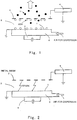
Fig. 5 of Patent Document 1 (seeFig. 1 of the present application) shows one example of a conventional electrostatic separation device. This conventional electrostatic separation device is configured such that electrodes are disposed on an upper side and a lower side, a gas diffusion plate electrode (laminated sintering porous electrode) having air permeability is disposed as alower side electrode 1, and awind box 6 disposed below thelower side electrode 1 blows air to fluidize powder. - As an
upper side electrode 2, a substantially flat plate mesh electrode having a large number of openings through which particles pass is disposed. Further, a vibrator or aknocker 5 is attached to give vibration to the entire device.Patent Document 1 describes a method for applying a DC high voltage between the upper and lower side electrodes, supplying to anelectrostatic separation zone 3 the particulate material (concentration of unburned components = electrically-conductive particle weight ratio of 2% to 5%) that is a mixture of electrically-conductive particles (unburned components) and insulating particles (ash components), and carrying out the electrostatic separation while applying vibration to the device. - However, in accordance with the method described in
Patent Document 1, there is a problem that in a case where the concentration of the unburned component of the particulate material that is the mixture of the electrically-conductive component and the insulating component is as high as 15% to 30%, the increase of the concentration of the electrically-conductive component in the air in theelectrostatic separation zone 3 is unavoidable, and the separation performance deteriorates due to the decrease of the insulation property and the generation of the spark. - Patent Document 1:
WO 2002/076620 - An object of the present invention is to provide an electrostatic separation method and an electrostatic separation device each of which solves the above problems associated with the prior art, can stably separate ash (into high unburned component ash and low unburned component ash) without generating the spark even in a case where the concentration of the unburned component in the coal ash produced by the boiler of the coal-fired power plant is as high as 15% to 30%, can reuse the high unburned component ash as fuel, and can reuse the low unburned component ash as, for example, an auxiliary material of concrete.
- The present invention was made as a result of diligent studies to solve the above problems, and it is defined by the appended
independent method claim 1 and theindependent apparatus claim 6. - The present invention has industrially useful, significant effects, for example, the present invention can provide an electrostatic separation method and an electrostatic separation device each of which can stably separate ash (into the high unburned component ash and the low unburned component ash) without generating the spark even in a case where the concentration of the unburned component in the coal ash produced by the boiler of the coal-fired power plant is as high as 15% to 30%, can reuse the high unburned component ash as fuel, and can reuse the low unburned component ash as, for example, the auxiliary material of concrete.
-
-
Fig. 1 is a diagram showing a conventional electrostatic separation device. -
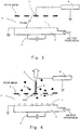
Fig. 2 is a diagram for explaining a mechanism of spark generation in the conventional electrostatic separation device. -
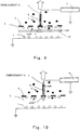
Fig. 3 is a diagram for explaining the mechanism of the spark generation in the conventional electrostatic separation device. -
Fig. 4 is a diagram showing an embodiment which uses a resin rod electrode in an electrostatic separation device of the present invention. -
Fig. 5 is a diagram showing an embodiment which use a flat plate electrode made of high dielectric resin in the electrostatic separation device of the present invention. -
Fig. 6 is a diagram for explaining a mechanism of preventing current generation in the electrostatic separation device of the present invention. -
Fig. 7 is adiagram showing Embodiment 1 which uses the resin rod electrode and air supply in the electrostatic separation device of the present invention. -
Fig. 8 is adiagram showing Embodiment 2 which uses the resin rod electrode, the air supply and a low dielectric in the electrostatic separation device of the present invention. -
Fig. 9 is adiagram showing Embodiment 3 which uses the resin rod electrode, an air pipe and the low dielectric in the electrostatic separation device of the present invention. -
Fig. 10 is adiagram showing Embodiment 4 which uses the resin rod electrode, the air pipe and the low dielectric in the electrostatic separation device of the present invention. -
Fig. 11 is adiagram showing Embodiment 5 which uses the resin rod electrode, the air pipe and a ring-shaped weight in the electrostatic separation device of the present invention. -
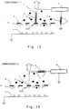
Fig. 12 is adiagram showing Embodiment 6 which uses the resin rod electrode and an intermediately inserted resin rod electrode in the electrostatic separation device of the present invention. -
Fig. 13 is adiagram showing Embodiment 7 which uses the resin rod electrode and the intermediately inserted resin rod electrode in the electrostatic separation device of the present invention. -
Fig. 14 is adiagram showing Embodiment 8 which uses the intermediately inserted resin rod electrode in the electrostatic separation device of the present invention. -
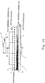
Fig. 15 is adiagram showing Embodiment 9 which uses the intermediately inserted resin rod electrode in the electrostatic separation device of the present invention. -
Fig. 16 is a diagram showing Examples of the electrostatic separation device of the present invention which carries out batch processing. -
Fig. 17 is a diagram showing Examples of the electrostatic separation device of the present invention which carries out continuous processing in the case of including aresin rod electrode 8. -
Fig. 18 is a diagram showing Examples of the electrostatic separation device of the present invention which carries out the continuous processing in the case of not including theresin rod electrode 8. - The present invention will be explained in detail with reference to
Figs. 2 to 18 . The present invention is limited to the embodiments shown in theFigs. 17 and18 ("Examples" 4-7). The embodiments 1-9 shown in theFigs. 4-15 and the Examples 1-3 shown inFig. 16 are merely presented as information useful for understanding the invention. - The present inventors have been diligently studying an ash separation technique (technique of separating into high unburned carbon ash and low unburned carbon ash) in a case where the concentration of the unburned carbon contained in the coal ash produced by a coal-fired boiler is as high as 15% to 30%. Hereinafter, explanations will be made on the assumption that the coal ash is used as the material.
- A small device (plane area of 100 mm (width) × 200 mm (length), distance between upper and lower electrodes of 80 mm) having the same function as the device described in
Patent Document 1 was actually prepared to confirm the problems of the above-described prior art, and a verification experiment was carried out. As shown inFig. 1 , the experiment was carried out such that a metal mesh electrode (mesh size of 15 mm, wire diameter of 1 mm) was prepared as a mesh electrode that is anupper side electrode 2, a DC highvoltage power source 4 directly supplied power to the metal mesh electrode, and the coal ash (unburned carbon concentration of 15% to 30%) was used as the material. Results of the experiment are shown below. - As a result of the experiment using the metal mesh, as shown in
Fig. 2 , it is found that the spark is generated from some portions between the upper and lower electrodes when the voltage is 5 KV or more, and the separation performance deteriorates. - Thus, this experiment has verified that the spark is generated by using the coal ash (unburned component concentration of 15% to 30%) in the case of the metal mesh electrode.
- Next, a mesh electrode (hereinafter referred to as "resin mesh electrode") made of high dielectric resin that is an insulator was prepared as an alternative to the metal mesh electrode for measures against the spark, and an experiment was carried out in the same manner as above.
- A resin mesh electrode (mesh obtained by making several tens of holes each having Φ10 on a flat plate having a thickness of 3 mm) used as the
mesh electrode 2 is made of high dielectric resin. Therefore, in a case where power is directly supplied to the resin mesh electrode from a metal terminal that is a feeding point of a DC high voltage power source, dipoles are generated in the resin. On this account, a potential that is equal to the potential of the supplied power can be uniformly applied to the surface of the resin mesh electrode, and the electrostatic separation can be carried out by utilizing this potential. This has already been found by the past various experiments, so that this was used in this experiment. - As a result of the experiment using the resin mesh, as shown in
Fig. 3 , it is found that the spark is generated between the metal terminal that is the feeding point and the lower side electrode when the voltage is 20 KV or more, and the separation performance deteriorates. - This experiment has also verified that the spark is generated although the voltage of the spark generation in this case is higher than that in the case of the metal mesh.
- Thus, since the spark is generated regardless of the material of the
mesh electrode 2 although the voltage level changes, the present inventors have studied the mechanism of the spark generation and the prevention of the spark generation as follows. - In the mechanism of the spark generation, qualitatively, corona discharge is generated at a portion where an electric field is strong, and an electron avalanche phenomenon occurs while ionizing ambient air. Although subsequent phenomenon is not described in detail, a plasma state thin discharge path (streamer) is eventually formed, an electrical short circuit is generated between the upper and lower electrodes, and electrons are continuously supplied from the power source. Therefore, a large current flows when viewed from the power source side. This phenomenon is visually recognized as the spark.
- Next, consideration is made quantitatively. As a result of study of one example of the metal mesh electrode, the following theoretical formula can be theoretically derived: where an electric field Ec (voltage for starting the ionization) for starting the corona discharge of the air is generally 3 KV/mm, the wire diameter of the metal mesh electrode is 1 mm (wire radius r = 0.5 mm), V denotes the voltage applied to the metal mesh electrode, and G denotes a space gap between the upper and lower electrodes.

- To obtain the space gap G where the ionization starts, the following formula is obtained by changing Formula (a).

- It is found that in a case where r of 0.5 mm, Ec of 3 KV/mm, and the applied voltage V of 5, 6, 7 or 8 KV are assigned in Formula (b), the ionization start space gap G becomes 14, 27, 53, or 103 mm.
- To be specific, if the concentration of the unburned carbon in the coal ash increases, the insulating property of the electrostatic separation zone deteriorates. Therefore, even if the space gap G between the upper and lower electrodes is 80 mm, the space gap G of 80 mm is equivalent to the shorter space gap G. Maybe because of this, in the case of the metal mesh electrode, the spark was generated even though the voltage was about 6 to 7 KV. Moreover, the spark generation voltage of the metal terminal that is the feeding point of the resin mesh electrode is somewhat high, that is, 20 KV or more. This is maybe because since part of a spark generation path bypasses the resin mesh electrode, this bypassing is equivalent to the increase of the space gap.
- In the case of focusing only on the metal mesh electrode, the wire diameter may be increased to prevent the spark generation. For example, by setting the wire diameter to be 2 mm (wire radius r = 1 mm) in the above conditions, the ionization start space gap G can be advantageously made to be 14 mm when the applied voltage V is 8 KV. However, the weight of the metal mesh electrode becomes heavy, and firm attachment is needed. In addition, there are no such commercial products, so that there may be a possibility that custom-made products need to be made. This is high in cost and is not economical.
- Therefore, for the purpose of prevention of the spark generation herein, preventing the occurrence of the electron avalanche phenomenon to the generation of the streamer was studied. As specific countermeasures, the problem was considered to be direct power supply from the metal terminal that is the feeding point of the DC high voltage power source to the metal mesh electrode (or the resin mesh electrode). As
Countermeasure 1, based on the idea that rapid supply of the electrons from the power source needs to be prevented, but the potential needs to be transmitted, conceived was the idea that the resin rod electrode 8 (which corresponds to a high dielectric resin element of the present invention and is hereinafter referred to as "resin rod electrode 8") made of the high dielectric resin is inserted between the mesh electrode 2 (that is the metal mesh electrode or the resin mesh electrode) and themetal terminal 7 that is the feeding point of the DC highvoltage power source 4, as shown inFig. 4 . - Therefore, even in a case where the concentration of the unburned component (C) in the
electrostatic separation zone 3 is as high as 15% to 30%, it is possible to prevent the spark generation without deteriorating the ash separation performance by preventing the rapid supply of the electrons from the power source. - Moreover, as
Countermeasure 2, conceived was the idea that a flat plate electrode (which corresponds to the high dielectric resin element of the present invention and is hereinafter referred to as "resin plate electrode") 2' not having the mesh shown inFig. 5 and made of the high dielectric resin is used as an alternative to themesh electrode 2. As a result of the actual experiment, it is found that even in a case where the concentration of the unburned component (C) in theelectrostatic separation zone 3 is as high as 15% to 30%, the spark generation is prevented without deteriorating the ash separation performance by preventing the rapid supply of the electrons from the power source. - Since the following explanation is common to the resin mesh electrode, the metal mesh electrode and the resin plate electrode, these electrodes are collectively called "upper side electrode".
- As the material of the high dielectric resin element of the present invention, any high dielectric resin, such as phenol resin or vinyl chloride resin, can be used.
- Although the spark generation can be prevented, a phenomenon that the current slightly flows occurs when a continuous running time of about ten minutes has passed. When the current increases gradually up to about 1 mA, a current limiting function (function of decreasing the voltage while maintaining the current to be the set current of 1 mA) of the DC high voltage power source works, the applied voltage decreases, so that the separation performance deteriorates. Therefore, the mechanism of the current generation and the prevention of the current generation are studied next.
- The following five items were estimated as causes of the current generation, and were verified using an experimental apparatus including a combination of the resin rod electrode and the resin mesh electrode. Thus, the causes of the current generation were investigated.
- The current of about 1 mA is actually flowing through the resin rod electrode.
- Since it is understood that the actual current value of the resin having the polymer structure was 10-11 (A/cm2) , and the current hardly flows, it is found that
Estimation 1 is not the cause of the current generation. - Positive and negative ions are generated by the ionization at the metal terminal that is the feeding point of power feeding from the DC high voltage power source to the resin rod electrode, and the ions are accumulated on the resin rod electrode and wall surfaces, thereby causing the current to flow.
- If the cause of the current generation is the ion accumulation, the current is expected to decrease immediately after the switching of the power source, since ion neutralization occurs by switching the polarity of the power source. However, the current decrease was not confirmed according to the experiment result. Therefore, it is found that
Estimation 2 is not the cause of the current generation. - The conductivity of the air containing fine powdered carbon increases, and thereby the current flows.
- After the load operation was carried out for sixty minutes, the current value has reached 0.1 mA. After that, the load operation was stopped. The current flow was investigated in this state. As a result of the experiment, the current of 0.1 mA has flown even after the load operation was stopped. Therefore, it is found that
Estimation 3 is not the cause of the current generation. - The current flows due to the current path formed by the powder adhered to the surface of the resin rod electrode.
- After the load operation was carried out for sixty minutes, the current value has reached 0.1 mA. After that, the load operation was stopped. The powder adhered to the surface of the resin rod electrode was removed in this state. As a result of the experiment, the current of 0.1 mA has flown even though the powder was removed. Therefore, it is found that
Estimation 4 is not the cause of the current generation. - The ionization occurs since the electric field becomes partially strong due to the adherence (adherence of micro projections) of the powder to the lower surface of the upper side electrode. Positive and negative ions generated by this ionization move to the power source side and the ground side, thus causing the current to flow.
- The powder adhered to the lower surface of the upper side electrode was removed by directly blowing air during the load operation. As a result of the experiment, it is confirmed that the current does not flow. Thus, it is found that the cause of the current generation is the adherence of the powder to the lower surface of the upper side electrode.
- Moreover, although it is found that the cause of the current generation is the adherence of the powder to the lower surface of the upper side electrode, an experiment was carried out to confirm whether the powder needs to be removed from the entire lower surface or part of the lower surface to prevent the current generation. As a result, it is found that the current does not flow by partially removing the powder adhered in the vicinity of the lower portion of the resin rod electrode.
- As a result of estimation of the mechanism of the current generation based on the results of the above various experiments, as shown in
Fig. 6 , by carrying out the load operation while applying the voltage, the powder adheres to the lower surface of theupper side electrode 2 by the electrostatic force. The electric field in the vicinity of the lower portion of theresin rod electrode 8 is stronger than that of the other portions of the upper side electrode. If the powder adheres, the powder becomes micro projections, the electric field on the surface of the projection is strong, the corona discharge starts gradually, positive and negative ions are generated by ionizing air, and the powder charged by the ions further adheres to and accumulates on the projections. As the thickness of this powder layer increases, the electric charge maintained in the powder increases, and the intensity of the electric field in the powder layer increases, so that positive and negative ions are generated increasingly. It is estimated that the positive and negative ions are attracted to the power source side and the ground side, the electron exchange is carried out on both sides, and the current flows when viewed from the power source side. - In summary, the rapid supply of the electrons from the power source is prevented by disposing the
resin rod electrode 8 on the upper portion of themesh electrode 2, such as the metal mesh electrode or the resin mesh electrode, or by using the resin plate electrode 2' as an alternative to the mesh electrode, and thus the spark can be suppressed. - The diameter of the
resin rod electrode 8 is desirably Φ5 to Φ150, and preferably Φ20 to Φ40, and the length of theresin rod electrode 8 is desirably 0 mm to 300 mm, and preferably 0 mm to 200 mm. Moreover, the thickness of each of the resin mesh electrode and the resin plate electrode is desirably 1 mm to 20 mm, and preferably 3 mm to 5 mm. - By partially removing the powder adhered to the lower surface of the upper side electrode, the current generation can be suppressed. Even in a case where it is difficult to remove the adhered powder, a resin rod electrode similar to the
resin rod electrode 8 is inserted into an intermediate point of the feeder line extending between the power source side and the ground side so that the positive and negative ions generated due to the adherence of the powder cannot exchange the electrons with the power source side or the ground side. This has an effect of suppressing the current generation, which has already been verified by an additional verification experiment, although details of the additional verification experiment are omitted herein (the resin rod electrode inserted into the intermediate point of the feeder line also corresponds to the high dielectric resin element of the present invention and is hereinafter referred to as "intermediately inserted resin rod electrode"). - Hereinafter, preferred embodiments of the electrostatic separation device of the present invention will be explained.
-
Embodiments 1 to 7 shows cases including theresin rod electrode 8, and Embodiments 8 and 9 shows cases not including theresin rod electrode 8. -
Fig. 7 is adiagram showing Embodiment 1 which uses means for removing the adhered powder by the resin rod electrode and air supply in the electrostatic separation device of the present invention. - An air pipe is extended from above the
upper side electrode 2 to the vicinity of the lower portion of theresin rod electrode 8 corresponding to the high dielectric resin element of the present invention, so that the powder is removed directly by the air. - The current flows by the ionization which is caused due to the powder adhered to the vicinity of the lower portion of the
resin rod electrode 8. Therefore, the current generation can be prevented by directly blowing the air to remove the adhered powder. - An area where the powder is removed is desirably the entire area, and preferably an area that is twice to four times as large as the diameter of the resin rod electrode.
- As the amount of air, the linear velocity of the air is desirably 1 m/s to 20 m/s, and preferably 5 m/s to 15 m/s.
-
Fig. 8 is adiagram showing Embodiment 2 which uses means for removing the adhered powder by the resin rod electrode and the air supply, and a low dielectric in the electrostatic separation device of the present invention. - A plate of a
low dielectric 9 is attached to the vicinity of the lower portion of theresin rod electrode 8 corresponding to the high dielectric resin element of the present invention, and the air pipe is extended from above theupper side electrode 2 to the vicinity of the lower portion of theresin rod electrode 8, so that the powder is removed directly by the air. - By attaching the plate of the
low dielectric 9 to the vicinity of the lower portion of theresin rod electrode 8, it is possible to reduce the amount of powder adhered. Therefore, it becomes easy to remove the powder by the air blow. - The material of the
low dielectric 9 may be any low dielectric material, such as Teflon (registered trademark) resin or silicon resin. -
Fig. 9 is adiagram showing Embodiment 3 which uses means for removing the adhered powder by the resin rod electrode and the air pipe, and the low dielectric in the electrostatic separation device of the present invention. - The plate of the
low dielectric 9 is attached to the vicinity of the lower portion of theresin rod electrode 8 corresponding to the high dielectric resin element of the present invention, and the air pipe is extended from below theupper side electrode 2 to the vicinity of the lower portion of theresin rod electrode 8, so that the powder is removed directly by the air. - By attaching the plate of the low dielectric to the vicinity of the lower portion of the
resin rod electrode 8, it is possible to reduce the amount of powder adhered. Therefore, it becomes easy to remove the powder by the air blow. - The distance between the air pipe and the
upper side electrode 2 may he determined in accordance with an area of a region which needs to be blown by the air. -
Fig. 10 is a diagram showing.Embodiment 4 which uses means for removing the adhered powder by the resin rod electrode and the air pipe, and the low dielectric in the electrostatic separation device of the present invention. - Air is supplied inside the
resin rod electrode 8 corresponding to the high dielectric resin element of the present invention, and a porous plate is attached to the vicinity of the lower portion, so that the powder is removed. - By supplying the air inside the
resin rod electrode 8, and attaching the porous plate 10 to the vicinity of the lower portion to remove the powder, it becomes unnecessary to provide the air pipe extended from outside, and it is possible to easily remove the powder. Instead of supplying the air inside the resin rod electrode, the air may be directly supplied to the porous plate using the air pipe. - The porous plate 10 may be determined for each experiment in light of the pressure loss and the clogging.
-
Fig. 11 is adiagram showing Embodiment 5 which uses means for removing the adhered powder by the resin rod electrode and the air pipe, and a ring-shaped weight in the electrostatic separation device of the present invention. - A ring-shaped weight 11 is attached to the
resin rod electrode 8 corresponding to the high dielectric resin element of the present invention, and in this state, the powder is removed. - By attaching the ring-shaped weight 11 to the
resin rod electrode 8, the vibration of the entire device is transmitted to the ring-shaped weight 11, which vibrates, and the powder adhered to the vicinity of the lower portion of theresin rod electrode 8 can be removed by this vibration. - The inner diameter of the ring-shaped weight 11 may be made larger than the diameter of the resin rod electrode by 1 mm or more.
- Moreover, the ring-shaped weight 11 is desirably 5 g to 300 g, and preferably 20 g to 100 g. The material of the ring-shaped weight 11 may be any material, such as rubber, resin, ceramic or metal. The shape of the weight is not limited to the ring, and may be a ball. Moreover, the weight may be disposed on the entire surface.
-
Fig. 12 is adiagram showing Embodiment 6 which uses the resin rod electrode and the intermediately inserted resin rod electrode in the electrostatic separation device of the present invention. - An intermediately inserted
resin rod electrode 12 corresponding to the high dielectric resin element of the present invention is inserted into the intermediate point of the feeder line extending from theresin rod electrode 8 to the DC highvoltage power source 4, and the following current countermeasure is carried out. - To be specific, the current flow is prevented by inserting the intermediately inserted
resin rod electrode 12 into the intermediate point of the feeder line so that the positive and negative ions generated by the adherence of the powder cannot exchange the electrons with the power source side. - The diameter of the inserted
resin rod electrode 12 is desirably Φ5 to Φ150, and preferably Φ20 to Φ40. The shape of the insertedresin rod electrode 12 is not limited to a round shape, and may be a square shape. The length of the insertedresin rod electrode 12 is desirably 2 mm to 500 mm, and preferably 50 mm to 100 mm. -
Fig. 13 is adiagram showing Embodiment 7 which uses the resin rod electrode and the intermediately inserted resin rod electrode in the electrostatic separation device of the present invention. - An intermediately inserted resin rod electrode 12' corresponding to the high dielectric resin element of the present invention is inserted into a ground wire of the DC high
voltage power source 4, and the current countermeasure is carried out. - The current flow is prevented by inserting the intermediately inserted resin rod electrode 12' into the intermediate point of the feeder line so that the positive and negative ions generated by the adherence of the powder cannot exchange the electrons with the ground side.
-
Fig. 14 is adiagram showing Embodiment 8 which uses the intermediately inserted resin rod electrode in the electrostatic separation device of the present invention. - The intermediately inserted
resin rod electrode 12 corresponding to the high dielectric resin element of the present invention is inserted into the intermediate point of the feeder line extending from theupper side electrode 2 to the DC highvoltage power source 4, and the current countermeasure is carried out. - The current flow is prevented by inserting the intermediately inserted
resin rod electrode 12 into the intermediate point of the feeder line so that the positive and negative ions generated by the adherence of the powder cannot exchange the electrons with the power source side. -
Fig. 15 is adiagram showing Embodiment 9 which uses the intermediately inserted resin rod electrode in the electrostatic separation device of the present invention. - The intermediately inserted resin rod electrode 12' corresponding to the high dielectric resin element of the present invention is inserted into the ground wire of the DC high
voltage power source 4, and the current countermeasure is carried out. - The current flow is prevented by inserting the intermediately inserted resin rod electrode 12' into the intermediate point of the feeder line so that the positive and negative ions generated by the adherence of the powder cannot exchange the electrons with the ground side.
- As the materials of the resin mesh electrode, the resin rod electrode and the resin plate electrode, any high dielectric resin, such as phenol resin or vinyl chloride resin, can be used.
- The electrostatic separation method and the electrostatic separation device of the present invention were used under the following conditions.
- An experiment was carried out in accordance with the following basic configuration and conditions using the electrostatic separation device which carries out batch processing shown in
Fig. 16 . - 1) Two-layer structure of upper side electrode
- (1) Mesh electrode 2 (resin mesh electrode) having a width of 100, a length of 200, and a thickness of 3
- (2)
Resin rod electrode 8 having a diameter of 20 and a length of 100
- 2) Gap between the upper and lower electrodes: 80 mm (vertical distance between the
lower side electrode 1 and the upper side electrode 2) - 3) Raw powder: Coal ash (100 g) having the unburned carbon concentration of 25%
- 4) Current countermeasure: Air blow by guiding air using the
air pipe 13 from the upper portion of the upper side electrode to the center of the lower surface of the upper side electrode
Area of a region where the adhered powder is removed:Range 14 that is a 50 mm square in the vicinity of the lower portion of the resin rod electrode
Linear velocity of blown air: 10 m/s - 5) Conditions of the vibration of the vibrator 5: Amplitude of 2 mm, Frequency of 28 Hz
- 6) Amount of air supplied for dispersion: 16 L/min
- The high unburned carbon ash was collected from a suction opening under the above conditions. As a result, the current value was about 10 µA. Moreover, as a result of the ash separation, the concentration of the carbon of the high unburned carbon ash was 68% (28 g), and the concentration of the carbon of the low unburned carbon ash was 8% (72 g).
- An experiment was carried out in accordance with the following basic configuration and conditions using the electrostatic separation device which carries out the batch processing shown in
Fig. 16 . - 1) Two-layer structure of upper side electrode
- (1) Mesh electrode 2 (resin mesh electrode) having a width of 100, a length of 200 and a thickness of 3
- (2)
Resin rod electrode 8 having a diameter of 20 and a length of 100
- 2) Gap between the upper and lower electrodes: 80 mm (vertical distance between the
lower side electrode 1 and the upper side electrode 2) - 3) Raw powder: Coal ash (100 g) having the unburned carbon concentration of 27%
- 4) Current countermeasure: Effects of
Countermeasures - Countermeasure 1: Air blow by guiding air using the
air pipe 13 from the upper portion of the upper electrode to the center of the lower surface of the upper side electrode, and the plate (50 mm square) of thelow dielectric 9 - Countermeasure 2: Air blow by guiding air using the
air pipe 15 from the lower portion of the upper electrode to the center of the lower surface of the upper side electrode, and the plate (50 mm square) of thelow dielectric 9 - Area of a region where the adhered powder is removed:
Range 14 that is a 50 mm square in the vicinity of the lower portion of the resin rod electrode
Linear velocity of blown air :10 m/s - 5) Conditions of the vibration of the vibrator 5: Amplitude of 2 mm, Frequency of 28 Hz
- 6) Amount of air supplied for dispersion: 16 L/min
- The high unburned carbon ash was collected from the suction opening under the above conditions. As a result, the experimental result of
Countermeasure 1 and the experimental result ofCountermeasure 2 were substantially the same as each other, and the current value was further low, that is, about 4 µA. As a result of the ash separation, the concentration of the carbon of the high unburned carbon ash was 70% (32 g), and the concentration of the carbon of the low unburned carbon ash was 7% (68 g). - An experiment was carried out in accordance with the following basic configuration and conditions using the electrostatic separation device which carries out the batch processing shown in
Fig. 16 . - 1) Two-layer structure of upper side electrode
- (1) Mesh electrode 2 (resin mesh electrode) having a width of 100, a length of 200 and a thickness of 3
- (2)
Resin rod electrode 8 having a diameter of 20 and a length of 100
- 2) Gap between the upper and lower electrodes: 80 mm (vertical distance between the
lower side electrode 1 and the upper side electrode 2) - 3) Raw powder: Coal ash (100 g) having the unburned carbon concentration of 21%
- 4) Current countermeasure: Air supply by causing air to pass through the inside of the resin rod electrode, and the area of the porous plate (50 mm square) (The configuration of the
resin rod electrode 8 is the same as the configuration shown inFig. 10 .)
Area of a region where the adhered powder is removed:Range 14 that is a 50 mm square in the vicinity of the lower portion of the resin rod electrode
Linear velocity of blown air: 5 m/s - 5) Conditions of the vibration of the vibrator 5: Amplitude of 2mm, Frequency of 28 Hz
- 6) Amount of air supplied for dispersion: 16 L/min
- The high unburned carbon ash was collected from the suction opening under the above conditions. As a result, the current value was further low, that is, about 2 µA. As a result of the ash separation, the concentration of the carbon of the high unburned carbon ash was 65% (25 g), and the concentration of the carbon of the low unburned carbon ash was 6% (75 g).
- An experiment was carried out in accordance with the following basic configuration and conditions using the electrostatic separation device which carries out the continuous processing shown in
Fig. 17 . - 1) Two-layer structure of upper side electrode
- (1) Mesh electrode 2 (resin mesh electrode) having a width of 200, a length of 1,600 and a thickness of 3
- (2) Four
Resin rod electrodes 8 each having a diameter of 20 and a length of 100
- 2) Gap between the upper and lower electrodes: 80 mm (vertical distance between the
lower side electrode 1 and the upper side electrode 2) - 3) Raw powder: Coal ash having the unburned carbon concentration of 24%
Amount of continuous supply: 100 kg/h - 4) Current countermeasure: Attaching of four ring-shaped weights 11 to the respective resin rod electrodes
Spec of each ring: Inner diameter of 22 mm, Weight of 75 g - 5) Conditions of the vibration of the vibrator 5: Amplitude of 2 mm, Frequency of 28 Hz
- 6) Amount of air supplied for dispersion: 260 L/min
- The unburned carbon ash was collected from the suction opening under the above conditions. As a result, the total current value of four resin rod electrodes was about 20 µA. As a result of the ash separation, the concentration of the carbon of the high unburned carbon ash was 67% (26 kg/h), and the concentration of the carbon of the low unburned carbon ash was 9% (74 kg/h).
- An experiment was carried out in accordance with the following basic configuration and conditions using the electrostatic separation device which carries out the continuous processing shown in
Fig. 17 . - 1) Two-layer structure of upper side electrode
- (1) Mesh electrode 2 (resin mesh electrode) having a width of 200, a length of 1,600 and a thickness of 3
- (2) Four
resin rod electrodes 8 each having a diameter of 20 and a length of 100
- 2) Gap between the upper and lower electrodes: 80 mm (vertical distance between the
lower side electrode 1 and the upper side electrode 2) - 3) Raw powder: Coal ash having the unburned carbon concentration of 29%
Amount of continuous supply: 100 kg/h - 4) Current countermeasure: Effects of
Countermeasures - Countermeasure 1: Insertion of the
resin rod electrode 12 in a supply line extending from the resin rod electrode to the DC high voltage power source
Countermeasure 2: Insertion of the resin rod electrode 12' in the ground wire of the DC high voltage power source
Spec of the inserted resin rod electrode: Diameter of 20, Length of 60 - 5) Conditions of the vibration of the vibrator 5: Amplitude of 2 mm, Frequency of 28 Hz
- 6) Amount of air supplied for dispersion: 260 L/min
- The high unburned carbon ash was collected from the suction opening under the above conditions. As a result, the experimental result of the of
Countermeasure 1 and the experimental result of the ofCountermeasure 2 were substantially the same as each other, and the total current value of four resin rod electrodes was about 2 µA. As a result of the ash separation, the concentration of the carbon of the high unburned carbon ash was 69% (33 kg/h), and the concentration of the carbon of the low unburned carbon ash was 9% (67 kg/h). - An experiment was carried out in accordance with the following basic configuration and conditions using the electrostatic separation device which carries out the continuous processing shown in
Fig. 18 . - 1) Two-layer structure of upper side electrode
Mesh electrode 2 (metal mesh electrode) having a width of 200, a length of 1,600 and a wire diameter of 1 - 2) Gap between the upper and lower electrodes: 80 mm (vertical distance between the
lower side electrode 1 and the upper side electrode 2) - 3) Raw powder: Coal ash having the unburned carbon concentration of 24%
Amount of continuous supply: 100 kg/h - 4) Current countermeasure: Insertion of the
resin rod electrode 12 in the supply line extending from the resin rod electrode to the DC high voltage power source
Spec of the inserted resin rod electrode: Diameter of 20, Length of 60 - 5) Conditions of the vibration of the vibrator 5: Amplitude of 2 mm, Frequency of 28 Hz
- 6) Amount of air supplied for dispersion: 260 L/min
- The high unburned carbon ash was collected from the suction opening under the above conditions. As a result, a spike-shaped current waveform became smooth, and the current value was about 30 µA. As a result of the ash separation, the concentration of the carbon of the high unburned carbon ash was 67% (26 kg/h), and the concentration of the carbon of the low unburned carbon ash was 9% (74 kg/h).
- An experiment was carried out in accordance with the following basic configuration and conditions using the electrostatic separation device which carries out the continuous processing shown in
Fig. 18 . - 1) Two-layer structure of upper side electrode
Resin plate electrode having a width of 200, a length of 1,600 and a thickness of 3 (alternative to the mesh electrode 2) - 2) Gap between the upper and lower electrodes: 80 mm (vertical distance between the
lower side electrode 1 and the upper side electrode 2) - 3) Raw powder: Coal ash having the unburned carbon concentration of 30%
Amount of continuous supply: 100 kg/h - 4) Current countermeasure: Insertion of the resin rod electrode 12' in the ground wire of the DC high voltage power source
Spec of the inserted resin rod electrode: Diameter of 20, Length of 60 - 5) Conditions of the vibration of the vibrator 5: Amplitude of 2 mm, Frequency of 28 Hz
- 6) Amount of air supplied for dispersion: 260 L/min
- The high unburned carbon ash was collected from the suction opening under the above conditions. As a result, the current value was about 25 µA. As a result of the ash separation, the concentration of the carbon of the high unburned carbon ash was 71% (35 kg/h), and the concentration of the carbon of the low unburned carbon ash was 8% (65 kg/h).
- Thus, the above Examples confirmed that even in a case where the concentration of the unburned component in the coal ash produced by the boiler in the coal-fired power plant is as high as 15% to 30%, it is possible to stably separate the ash (into the high unburned component ash and the low unburned component ash) without generating the spark.
Claims (10)
- An electrostatic separation method for separating unburned carbon ash contained in coal ash by an electrostatic force, comprising the steps of:disposing a first side electrode (1) and a second side electrode (2); andgenerating a DC electric field between the first side electrode and the second side electrode,vibrating a case accommodating the first side electrode (1) and the second side electrode (2),characterized byproviding a dielectric resin element (8, 12, 12') in a circuit for applying a voltage between the first side electrode (1) and the second side electrode (2);inserting intermediately the dielectric resin element (12, 12') into a portion of a feeder line extending between the second side electrode (2) and the DC power source (4), and/or into a ground wire of the DC power source (4);sandwiching the dielectric resin element (12, 12') by a pair of metal terminals (7, 7'); anddisposing the dielectric resin element (12, 12') outside of the case.
- The electrostatic separation method according to claim 1, wherein the second side electrode (2) includes the dielectric resin element (8), and the DC electric field is generated between the first side electrode (1) and the second side electrode (2).
- The electrostatic separation method according to claim 1 or 2, wherein the second side electrode (2) is a mesh electrode including the dielectric resin element (8) having a rod shape.
- The electrostatic separation method according to claim 1 or 2, wherein the second side electrode is a flat plate electrode (2') made of dielectric resin.
- The electrostatic separation method according to any one of claims 1 to 4, further comprising the step of removing powder adhered to the second side electrode (2).
- An electrostatic separation device for separating unburned carbon ash contained in coal ash by an electrostatic force, comprising:a first side electrode (1);a second side electrode (2) disposed above the first side electrode (1) with a predetermined distance therebetween; anda circuit for applying a voltage between the first side electrode (1) and the second side electrode, anda vibrator (5) configured to vibrate a case accommodating the first side electrode (1) and the second side electrode (2),characterized bya dielectric resin element (8, 12, 12') provided in the circuit; wherein:the dielectric resin element (12, 12') is intermediately inserted into a portion of a feeder line between the second side electrode (2) and the DC power source (4), and/or into a ground wire of the DC power source (4);the dielectric resin element (12, 12') is sandwiched by a pair of metal terminals (7, 7'); andthe dielectric resin element (12, 12') is disposed outside of the case.
- The electrostatic separation device according to claim 6, further comprising:
a DC power source (4) connected to at least one of the first side electrode (1) and the second side electrode (2) and arranged to apply a voltage between the first side electrode and the second side electrode, wherein:
the second side electrode includes the dielectric resin element (8). - The electrostatic separation device according to claim 6 or 7, wherein the second side electrode comprises a resin rod electrode (8) made of dielectric resin and a mesh electrode (2) having a large number of openings which allow the coal ash to pass therethrough.
- The electrostatic separation device according to claim 6 or 7, wherein the second side electrode is a flat plate electrode (2') made of dielectric resin.
- The electrostatic separation device according to any one of claims 6 to 9, wherein the dielectric resin element (12, 12') is a dielectric resin rod.
Applications Claiming Priority (2)
| Application Number | Priority Date | Filing Date | Title |
|---|---|---|---|
| JP2005312801A JP4749118B2 (en) | 2005-10-27 | 2005-10-27 | Electrostatic separation method and electrostatic separation device |
| PCT/JP2006/321323 WO2007049667A1 (en) | 2005-10-27 | 2006-10-26 | Electrostatic separation method and electrostatic separator |
Publications (3)
| Publication Number | Publication Date |
|---|---|
| EP1941949A1 EP1941949A1 (en) | 2008-07-09 |
| EP1941949A4 EP1941949A4 (en) | 2011-04-27 |
| EP1941949B1 true EP1941949B1 (en) | 2019-05-15 |
Family
ID=37967777
Family Applications (1)
| Application Number | Title | Priority Date | Filing Date |
|---|---|---|---|
| EP06822299.1A Not-in-force EP1941949B1 (en) | 2005-10-27 | 2006-10-26 | Electrostatic separation method and electrostatic separator |
Country Status (6)
| Country | Link |
|---|---|
| US (2) | US8071904B2 (en) |
| EP (1) | EP1941949B1 (en) |
| JP (1) | JP4749118B2 (en) |
| KR (1) | KR100940082B1 (en) |
| CN (1) | CN101267890B (en) |
| WO (1) | WO2007049667A1 (en) |
Families Citing this family (14)
| Publication number | Priority date | Publication date | Assignee | Title |
|---|---|---|---|---|
| JP4749118B2 (en) * | 2005-10-27 | 2011-08-17 | 新日本製鐵株式会社 | Electrostatic separation method and electrostatic separation device |
| DE102010026445A1 (en) * | 2010-07-08 | 2012-01-12 | Evonik Degussa Gmbh | Fly ash separation by corona discharge |
| WO2016072540A1 (en) * | 2014-11-06 | 2016-05-12 | 군산대학교산학협력단 | Method for removing unburned carbon of fly ash using plasma |
| KR101547939B1 (en) | 2015-03-19 | 2015-08-28 | 동아대학교 산학협력단 | Recovery of unburned carbon from bottom ash using a Corona discharging Electroststic Separation |
| CN105226344B (en) * | 2015-11-09 | 2017-12-29 | 中国矿业大学 | A kind of recovery method of cobalt in waste lithium ion batteries acid lithium and graphite |
| CN105618732B (en) * | 2015-12-29 | 2017-07-25 | 北京钢研高纳科技股份有限公司 | A kind of preparation method of superalloy powder |
| JP6784025B2 (en) * | 2016-01-12 | 2020-11-11 | 三菱マテリアル株式会社 | How to make fly ash |
| JP6733254B2 (en) * | 2016-03-28 | 2020-07-29 | 三菱マテリアル株式会社 | Fly ash manufacturing method |
| JP6850983B2 (en) * | 2017-01-30 | 2021-03-31 | 三菱マテリアル株式会社 | How to reduce the amount of unburned carbon in coal ash |
| JP7229505B2 (en) * | 2018-05-21 | 2023-02-28 | 国立大学法人山形大学 | Electrostatic adsorption device |
| CN110885076B (en) * | 2019-12-23 | 2021-05-25 | 哈尔滨工业大学 | Method for efficiently, continuously and selectively separating carbon nanotubes in gas phase |
| US11986839B2 (en) * | 2020-10-23 | 2024-05-21 | Kawasaki Jukogyo Kabushiki Kaisha | Electrostatic separator |
| WO2022085182A1 (en) * | 2020-10-23 | 2022-04-28 | 川崎重工業株式会社 | Electrostatic separation device and method |
| KR102725876B1 (en) * | 2022-03-23 | 2024-11-04 | 한국핵융합에너지연구원 | Sorting apparatus for dielectric powder |
Citations (3)
| Publication number | Priority date | Publication date | Assignee | Title |
|---|---|---|---|---|
| US5829598A (en) * | 1995-04-28 | 1998-11-03 | Separation Technologies, Inc. | Method and apparatus for electrostatic separation |
| JP2001121033A (en) * | 1999-10-27 | 2001-05-08 | Mitsubishi Electric Corp | Electric dust collector |
| JP2004025128A (en) * | 2002-06-28 | 2004-01-29 | Hitachi Zosen Corp | Vibration sorter for conductive and plastic materials |
Family Cites Families (30)
| Publication number | Priority date | Publication date | Assignee | Title |
|---|---|---|---|---|
| US2689648A (en) * | 1952-02-18 | 1954-09-21 | Doenges Long Motors Inc | Separation of metallic from nonmetallic particles |
| US2847124A (en) * | 1955-02-08 | 1958-08-12 | Gen Mills Inc | Suppressor electrode for a perforated type of electrostatic separator machine |
| US3331192A (en) * | 1963-10-14 | 1967-07-18 | Floyd V Peterson | Electrical precipitator apparatus of the liquid spray type |
| CA984765A (en) * | 1971-11-02 | 1976-03-02 | James H. Vincent | Electrostatic precipitator employing dielectric grids |
| US3814879A (en) * | 1971-03-09 | 1974-06-04 | Westinghouse Electric Corp | Circuit interrupter with improved trap for removing particles from fluid insulating material |
| US3991312A (en) * | 1975-11-25 | 1976-11-09 | General Electric Company | Ionization chamber |
| US4172028A (en) * | 1978-09-29 | 1979-10-23 | Electro-Power-Tech., Inc. | Fine particle separation by electrostatically induced oscillation |
| US4247390A (en) * | 1978-10-23 | 1981-01-27 | Knoll Frank S | Method of separating vermiculite from the associated gangue |
| DE3120945A1 (en) * | 1980-05-28 | 1982-04-08 | Fuji Electric Co., Ltd., Kawasaki, Kanagawa | ELECTROSTATIC SORTING DEVICE |
| US4440638A (en) * | 1982-02-16 | 1984-04-03 | U.T. Board Of Regents | Surface field-effect device for manipulation of charged species |
| JPS60148044A (en) | 1984-01-13 | 1985-08-05 | Toshiba Corp | Fluorescent lamp |
| JPS60148044U (en) * | 1984-03-09 | 1985-10-01 | 三菱重工業株式会社 | Separation and recovery equipment for powder and granular materials |
| JPH02108747U (en) * | 1989-02-17 | 1990-08-29 | ||
| JP2529030Y2 (en) * | 1990-05-10 | 1997-03-12 | ミドリ安全工業株式会社 | Electric precipitator collector |
| JPH04158224A (en) * | 1990-10-22 | 1992-06-01 | Toyota Tsusho Kk | Level detecting circuit |
| JPH04193362A (en) * | 1990-11-28 | 1992-07-13 | Hitachi Ltd | Electric dust collector |
| JPH069871B2 (en) * | 1990-11-30 | 1994-02-09 | アキレス株式会社 | Welding method for thermoplastic synthetic resin sheet |
| JPH0645648U (en) * | 1992-10-15 | 1994-06-21 | 株式会社ゼクセル | Automotive air purifier |
| JPH078836A (en) * | 1993-06-21 | 1995-01-13 | Daikin Ind Ltd | Dust collecting electrode plate for electric dust collecting element |
| JPH08179590A (en) * | 1994-12-27 | 1996-07-12 | Sharp Corp | Charging device and manufacturing method thereof |
| JP3895771B2 (en) * | 1996-04-25 | 2007-03-22 | セパレーション・テクノロジーズ・エルエルシー | Electrostatic separation method and apparatus |
| DE19913614C1 (en) * | 1999-03-25 | 2000-05-11 | Fraunhofer Ges Forschung | Electrical discharge method for treating exhaust fumes in which extensions on earthed electrode are perforated to allow passage of gas through them |
| US6320148B1 (en) * | 1999-08-05 | 2001-11-20 | Roe-Hoan Yoon | Electrostatic method of separating particulate materials |
| US6498313B1 (en) * | 1999-12-23 | 2002-12-24 | University Of Kentucky Research Foundation | Electrostatic particle separation system, apparatus, and related method |
| DE60234328D1 (en) * | 2001-03-27 | 2009-12-24 | Kawasaki Heavy Ind Ltd | METHOD FOR THE ELECTROSTATIC SEPARATION OF PARTICLES, DEVICE FOR THE ELECTROSTATIC SEPARATION OF PARTICLES AND PROCESSING SYSTEM |
| US6797908B2 (en) * | 2002-04-10 | 2004-09-28 | Outokumpu Oyj | High-tension electrostatic classifier and separator, and associated method |
| WO2005069460A1 (en) * | 2004-01-13 | 2005-07-28 | Daikin Industries, Ltd. | Discharge device and air cleaning device |
| JP2006043684A (en) * | 2004-06-30 | 2006-02-16 | Nippon Steel Corp | Ash separator, ash separation method, and unburned carbon separation method using the same |
| JP4749118B2 (en) * | 2005-10-27 | 2011-08-17 | 新日本製鐵株式会社 | Electrostatic separation method and electrostatic separation device |
| KR101610024B1 (en) * | 2008-12-01 | 2016-04-21 | 삼성전자 주식회사 | Electric precipitator and electrode thereof |
-
2005
- 2005-10-27 JP JP2005312801A patent/JP4749118B2/en not_active Expired - Fee Related
-
2006
- 2006-10-26 KR KR1020087004870A patent/KR100940082B1/en not_active Expired - Fee Related
- 2006-10-26 CN CN2006800342163A patent/CN101267890B/en not_active Expired - Fee Related
- 2006-10-26 WO PCT/JP2006/321323 patent/WO2007049667A1/en not_active Ceased
- 2006-10-26 EP EP06822299.1A patent/EP1941949B1/en not_active Not-in-force
- 2006-10-26 US US11/991,903 patent/US8071904B2/en not_active Expired - Fee Related
-
2011
- 2011-10-27 US US13/283,486 patent/US8653394B2/en not_active Expired - Fee Related
Patent Citations (3)
| Publication number | Priority date | Publication date | Assignee | Title |
|---|---|---|---|---|
| US5829598A (en) * | 1995-04-28 | 1998-11-03 | Separation Technologies, Inc. | Method and apparatus for electrostatic separation |
| JP2001121033A (en) * | 1999-10-27 | 2001-05-08 | Mitsubishi Electric Corp | Electric dust collector |
| JP2004025128A (en) * | 2002-06-28 | 2004-01-29 | Hitachi Zosen Corp | Vibration sorter for conductive and plastic materials |
Also Published As
| Publication number | Publication date |
|---|---|
| US20090065402A1 (en) | 2009-03-12 |
| EP1941949A1 (en) | 2008-07-09 |
| CN101267890B (en) | 2011-01-12 |
| CN101267890A (en) | 2008-09-17 |
| US20120043261A1 (en) | 2012-02-23 |
| JP2007117873A (en) | 2007-05-17 |
| WO2007049667A1 (en) | 2007-05-03 |
| KR100940082B1 (en) | 2010-02-02 |
| EP1941949A4 (en) | 2011-04-27 |
| US8653394B2 (en) | 2014-02-18 |
| US8071904B2 (en) | 2011-12-06 |
| KR20080033474A (en) | 2008-04-16 |
| JP4749118B2 (en) | 2011-08-17 |
Similar Documents
| Publication | Publication Date | Title |
|---|---|---|
| US8653394B2 (en) | Electrostatic separation method and electrostatic separation device | |
| US4726812A (en) | Method for electrostatically charging up solid or liquid particles suspended in a gas stream by means of ions | |
| CA2362721C (en) | Method and process for separating materials in the form of particles and/or drops from a gas | |
| CA2496381A1 (en) | Grid type electrostatic separator/collector and method of using same | |
| KR20120040128A (en) | Clean corona gas ionization for static charge neutralization | |
| FI981169A0 (en) | Method and apparatus for separating particles from an air stream | |
| US20140352535A1 (en) | Electronic fine dust separator | |
| US20250025890A1 (en) | Air filtering device for an air conditioner | |
| WO2009059451A1 (en) | An electrostatic precipitator | |
| TWI879849B (en) | Electric dust collector | |
| US6482253B1 (en) | Powder charging apparatus | |
| JP2001121033A (en) | Electric dust collector | |
| JP2017124343A (en) | Production method of fly ash | |
| WO2013051931A1 (en) | Particle catch arrangement for catching particles from a polluted particle flow | |
| JPH10235228A (en) | Electrostatic sorting device | |
| JP2000021596A (en) | Air ionizing device and method | |
| JP2001096192A (en) | Electric dust collector | |
| KR0165072B1 (en) | Electric dust filter of air purifier | |
| JP2562557B2 (en) | Electric dust collector charging method | |
| JP2005066591A (en) | Unburned carbon separator and separation method | |
| JP4221501B2 (en) | Aerosol charge neutralizer | |
| CN211914182U (en) | Air purification apparatus for separating airborne particles from an air stream | |
| CA2674829A1 (en) | Grid type electrostatic separator/collector and method of using same | |
| KR102099564B1 (en) | Device for electrostatic spraying based on high voltage with parallel structure | |
| KR20080083855A (en) | Multi-stage variable particle size separator |
Legal Events
| Date | Code | Title | Description |
|---|---|---|---|
| PUAI | Public reference made under article 153(3) epc to a published international application that has entered the european phase |
Free format text: ORIGINAL CODE: 0009012 |
|
| 17P | Request for examination filed |
Effective date: 20080306 |
|
| AK | Designated contracting states |
Kind code of ref document: A1 Designated state(s): AT BE BG CH CY CZ DE DK EE ES FI FR GB GR HU IE IS IT LI LT LU LV MC NL PL PT RO SE SI SK TR |
|
| A4 | Supplementary search report drawn up and despatched |
Effective date: 20110328 |
|
| RIC1 | Information provided on ipc code assigned before grant |
Ipc: B03C 3/68 20060101ALI20110322BHEP Ipc: B03C 7/02 20060101AFI20070622BHEP Ipc: B03C 3/64 20060101ALI20110322BHEP Ipc: B09B 5/00 20060101ALI20110322BHEP |
|
| RAP1 | Party data changed (applicant data changed or rights of an application transferred) |
Owner name: KAWASAKI JUKOGYO KABUSHIKI KAISHA |
|
| DAX | Request for extension of the european patent (deleted) | ||
| 17Q | First examination report despatched |
Effective date: 20140620 |
|
| GRAP | Despatch of communication of intention to grant a patent |
Free format text: ORIGINAL CODE: EPIDOSNIGR1 |
|
| STAA | Information on the status of an ep patent application or granted ep patent |
Free format text: STATUS: GRANT OF PATENT IS INTENDED |
|
| RIC1 | Information provided on ipc code assigned before grant |
Ipc: B09B 5/00 20060101ALI20181123BHEP Ipc: B03C 3/68 20060101ALI20181123BHEP Ipc: B03C 3/09 20060101ALI20181123BHEP Ipc: B03C 7/02 20060101AFI20181123BHEP Ipc: B03C 3/64 20060101ALI20181123BHEP |
|
| INTG | Intention to grant announced |
Effective date: 20181218 |
|
| GRAS | Grant fee paid |
Free format text: ORIGINAL CODE: EPIDOSNIGR3 |
|
| GRAA | (expected) grant |
Free format text: ORIGINAL CODE: 0009210 |
|
| STAA | Information on the status of an ep patent application or granted ep patent |
Free format text: STATUS: THE PATENT HAS BEEN GRANTED |
|
| AK | Designated contracting states |
Kind code of ref document: B1 Designated state(s): AT BE BG CH CY CZ DE DK EE ES FI FR GB GR HU IE IS IT LI LT LU LV MC NL PL PT RO SE SI SK TR |
|
| REG | Reference to a national code |
Ref country code: CH Ref legal event code: EP Ref country code: GB Ref legal event code: FG4D |
|
| REG | Reference to a national code |
Ref country code: DE Ref legal event code: R096 Ref document number: 602006057991 Country of ref document: DE |
|
| REG | Reference to a national code |
Ref country code: IE Ref legal event code: FG4D |
|
| REG | Reference to a national code |
Ref country code: NL Ref legal event code: MP Effective date: 20190515 |
|
| REG | Reference to a national code |
Ref country code: LT Ref legal event code: MG4D |
|
| PG25 | Lapsed in a contracting state [announced via postgrant information from national office to epo] |
Ref country code: SE Free format text: LAPSE BECAUSE OF FAILURE TO SUBMIT A TRANSLATION OF THE DESCRIPTION OR TO PAY THE FEE WITHIN THE PRESCRIBED TIME-LIMIT Effective date: 20190515 Ref country code: PT Free format text: LAPSE BECAUSE OF FAILURE TO SUBMIT A TRANSLATION OF THE DESCRIPTION OR TO PAY THE FEE WITHIN THE PRESCRIBED TIME-LIMIT Effective date: 20190915 Ref country code: FI Free format text: LAPSE BECAUSE OF FAILURE TO SUBMIT A TRANSLATION OF THE DESCRIPTION OR TO PAY THE FEE WITHIN THE PRESCRIBED TIME-LIMIT Effective date: 20190515 Ref country code: ES Free format text: LAPSE BECAUSE OF FAILURE TO SUBMIT A TRANSLATION OF THE DESCRIPTION OR TO PAY THE FEE WITHIN THE PRESCRIBED TIME-LIMIT Effective date: 20190515 Ref country code: LT Free format text: LAPSE BECAUSE OF FAILURE TO SUBMIT A TRANSLATION OF THE DESCRIPTION OR TO PAY THE FEE WITHIN THE PRESCRIBED TIME-LIMIT Effective date: 20190515 Ref country code: NL Free format text: LAPSE BECAUSE OF FAILURE TO SUBMIT A TRANSLATION OF THE DESCRIPTION OR TO PAY THE FEE WITHIN THE PRESCRIBED TIME-LIMIT Effective date: 20190515 |
|
| PG25 | Lapsed in a contracting state [announced via postgrant information from national office to epo] |
Ref country code: BG Free format text: LAPSE BECAUSE OF FAILURE TO SUBMIT A TRANSLATION OF THE DESCRIPTION OR TO PAY THE FEE WITHIN THE PRESCRIBED TIME-LIMIT Effective date: 20190815 Ref country code: LV Free format text: LAPSE BECAUSE OF FAILURE TO SUBMIT A TRANSLATION OF THE DESCRIPTION OR TO PAY THE FEE WITHIN THE PRESCRIBED TIME-LIMIT Effective date: 20190515 Ref country code: GR Free format text: LAPSE BECAUSE OF FAILURE TO SUBMIT A TRANSLATION OF THE DESCRIPTION OR TO PAY THE FEE WITHIN THE PRESCRIBED TIME-LIMIT Effective date: 20190816 |
|
| REG | Reference to a national code |
Ref country code: AT Ref legal event code: MK05 Ref document number: 1132821 Country of ref document: AT Kind code of ref document: T Effective date: 20190515 |
|
| PG25 | Lapsed in a contracting state [announced via postgrant information from national office to epo] |
Ref country code: EE Free format text: LAPSE BECAUSE OF FAILURE TO SUBMIT A TRANSLATION OF THE DESCRIPTION OR TO PAY THE FEE WITHIN THE PRESCRIBED TIME-LIMIT Effective date: 20190515 Ref country code: AT Free format text: LAPSE BECAUSE OF FAILURE TO SUBMIT A TRANSLATION OF THE DESCRIPTION OR TO PAY THE FEE WITHIN THE PRESCRIBED TIME-LIMIT Effective date: 20190515 Ref country code: DK Free format text: LAPSE BECAUSE OF FAILURE TO SUBMIT A TRANSLATION OF THE DESCRIPTION OR TO PAY THE FEE WITHIN THE PRESCRIBED TIME-LIMIT Effective date: 20190515 Ref country code: CZ Free format text: LAPSE BECAUSE OF FAILURE TO SUBMIT A TRANSLATION OF THE DESCRIPTION OR TO PAY THE FEE WITHIN THE PRESCRIBED TIME-LIMIT Effective date: 20190515 Ref country code: RO Free format text: LAPSE BECAUSE OF FAILURE TO SUBMIT A TRANSLATION OF THE DESCRIPTION OR TO PAY THE FEE WITHIN THE PRESCRIBED TIME-LIMIT Effective date: 20190515 Ref country code: SK Free format text: LAPSE BECAUSE OF FAILURE TO SUBMIT A TRANSLATION OF THE DESCRIPTION OR TO PAY THE FEE WITHIN THE PRESCRIBED TIME-LIMIT Effective date: 20190515 |
|
| REG | Reference to a national code |
Ref country code: DE Ref legal event code: R097 Ref document number: 602006057991 Country of ref document: DE |
|
| PLBE | No opposition filed within time limit |
Free format text: ORIGINAL CODE: 0009261 |
|
| STAA | Information on the status of an ep patent application or granted ep patent |
Free format text: STATUS: NO OPPOSITION FILED WITHIN TIME LIMIT |
|
| PG25 | Lapsed in a contracting state [announced via postgrant information from national office to epo] |
Ref country code: TR Free format text: LAPSE BECAUSE OF FAILURE TO SUBMIT A TRANSLATION OF THE DESCRIPTION OR TO PAY THE FEE WITHIN THE PRESCRIBED TIME-LIMIT Effective date: 20190515 |
|
| 26N | No opposition filed |
Effective date: 20200218 |
|
| PG25 | Lapsed in a contracting state [announced via postgrant information from national office to epo] |
Ref country code: PL Free format text: LAPSE BECAUSE OF FAILURE TO SUBMIT A TRANSLATION OF THE DESCRIPTION OR TO PAY THE FEE WITHIN THE PRESCRIBED TIME-LIMIT Effective date: 20190515 |
|
| PG25 | Lapsed in a contracting state [announced via postgrant information from national office to epo] |
Ref country code: SI Free format text: LAPSE BECAUSE OF FAILURE TO SUBMIT A TRANSLATION OF THE DESCRIPTION OR TO PAY THE FEE WITHIN THE PRESCRIBED TIME-LIMIT Effective date: 20190515 Ref country code: MC Free format text: LAPSE BECAUSE OF FAILURE TO SUBMIT A TRANSLATION OF THE DESCRIPTION OR TO PAY THE FEE WITHIN THE PRESCRIBED TIME-LIMIT Effective date: 20190515 |
|
| REG | Reference to a national code |
Ref country code: CH Ref legal event code: PL |
|
| PG25 | Lapsed in a contracting state [announced via postgrant information from national office to epo] |
Ref country code: LU Free format text: LAPSE BECAUSE OF NON-PAYMENT OF DUE FEES Effective date: 20191026 Ref country code: LI Free format text: LAPSE BECAUSE OF NON-PAYMENT OF DUE FEES Effective date: 20191031 Ref country code: CH Free format text: LAPSE BECAUSE OF NON-PAYMENT OF DUE FEES Effective date: 20191031 |
|
| REG | Reference to a national code |
Ref country code: BE Ref legal event code: MM Effective date: 20191031 |
|
| PG25 | Lapsed in a contracting state [announced via postgrant information from national office to epo] |
Ref country code: BE Free format text: LAPSE BECAUSE OF NON-PAYMENT OF DUE FEES Effective date: 20191031 |
|
| PG25 | Lapsed in a contracting state [announced via postgrant information from national office to epo] |
Ref country code: IE Free format text: LAPSE BECAUSE OF NON-PAYMENT OF DUE FEES Effective date: 20191026 |
|
| PG25 | Lapsed in a contracting state [announced via postgrant information from national office to epo] |
Ref country code: CY Free format text: LAPSE BECAUSE OF FAILURE TO SUBMIT A TRANSLATION OF THE DESCRIPTION OR TO PAY THE FEE WITHIN THE PRESCRIBED TIME-LIMIT Effective date: 20190515 |
|
| PG25 | Lapsed in a contracting state [announced via postgrant information from national office to epo] |
Ref country code: IS Free format text: LAPSE BECAUSE OF FAILURE TO SUBMIT A TRANSLATION OF THE DESCRIPTION OR TO PAY THE FEE WITHIN THE PRESCRIBED TIME-LIMIT Effective date: 20190915 |
|
| PG25 | Lapsed in a contracting state [announced via postgrant information from national office to epo] |
Ref country code: HU Free format text: LAPSE BECAUSE OF FAILURE TO SUBMIT A TRANSLATION OF THE DESCRIPTION OR TO PAY THE FEE WITHIN THE PRESCRIBED TIME-LIMIT; INVALID AB INITIO Effective date: 20061026 |
|
| PGFP | Annual fee paid to national office [announced via postgrant information from national office to epo] |
Ref country code: GB Payment date: 20220901 Year of fee payment: 17 |
|
| PGFP | Annual fee paid to national office [announced via postgrant information from national office to epo] |
Ref country code: FR Payment date: 20220908 Year of fee payment: 17 |
|
| PGFP | Annual fee paid to national office [announced via postgrant information from national office to epo] |
Ref country code: IT Payment date: 20220913 Year of fee payment: 17 Ref country code: DE Payment date: 20220621 Year of fee payment: 17 |
|
| REG | Reference to a national code |
Ref country code: DE Ref legal event code: R119 Ref document number: 602006057991 Country of ref document: DE |
|
| GBPC | Gb: european patent ceased through non-payment of renewal fee |
Effective date: 20231026 |
|
| PG25 | Lapsed in a contracting state [announced via postgrant information from national office to epo] |
Ref country code: GB Free format text: LAPSE BECAUSE OF NON-PAYMENT OF DUE FEES Effective date: 20231026 |
|
| PG25 | Lapsed in a contracting state [announced via postgrant information from national office to epo] |
Ref country code: GB Free format text: LAPSE BECAUSE OF NON-PAYMENT OF DUE FEES Effective date: 20231026 Ref country code: FR Free format text: LAPSE BECAUSE OF NON-PAYMENT OF DUE FEES Effective date: 20231031 Ref country code: DE Free format text: LAPSE BECAUSE OF NON-PAYMENT OF DUE FEES Effective date: 20240501 |
|
| PG25 | Lapsed in a contracting state [announced via postgrant information from national office to epo] |
Ref country code: IT Free format text: LAPSE BECAUSE OF NON-PAYMENT OF DUE FEES Effective date: 20231026 |
|
| PG25 | Lapsed in a contracting state [announced via postgrant information from national office to epo] |
Ref country code: IT Free format text: LAPSE BECAUSE OF NON-PAYMENT OF DUE FEES Effective date: 20231026 |