EP1941920A1 - Blood filter device and method of manufacturing the same - Google Patents
Blood filter device and method of manufacturing the same Download PDFInfo
- Publication number
- EP1941920A1 EP1941920A1 EP06781688A EP06781688A EP1941920A1 EP 1941920 A1 EP1941920 A1 EP 1941920A1 EP 06781688 A EP06781688 A EP 06781688A EP 06781688 A EP06781688 A EP 06781688A EP 1941920 A1 EP1941920 A1 EP 1941920A1
- Authority
- EP
- European Patent Office
- Prior art keywords
- filter
- retaining portion
- blood
- pleats
- housing
- Prior art date
- Legal status (The legal status is an assumption and is not a legal conclusion. Google has not performed a legal analysis and makes no representation as to the accuracy of the status listed.)
- Granted
Links
Images





Classifications
-
- A—HUMAN NECESSITIES
- A61—MEDICAL OR VETERINARY SCIENCE; HYGIENE
- A61M—DEVICES FOR INTRODUCING MEDIA INTO, OR ONTO, THE BODY; DEVICES FOR TRANSDUCING BODY MEDIA OR FOR TAKING MEDIA FROM THE BODY; DEVICES FOR PRODUCING OR ENDING SLEEP OR STUPOR
- A61M1/00—Suction or pumping devices for medical purposes; Devices for carrying-off, for treatment of, or for carrying-over, body-liquids; Drainage systems
- A61M1/36—Other treatment of blood in a by-pass of the natural circulatory system, e.g. temperature adaptation, irradiation ; Extra-corporeal blood circuits
- A61M1/3621—Extra-corporeal blood circuits
- A61M1/3627—Degassing devices; Buffer reservoirs; Drip chambers; Blood filters
-
- A—HUMAN NECESSITIES
- A61—MEDICAL OR VETERINARY SCIENCE; HYGIENE
- A61M—DEVICES FOR INTRODUCING MEDIA INTO, OR ONTO, THE BODY; DEVICES FOR TRANSDUCING BODY MEDIA OR FOR TAKING MEDIA FROM THE BODY; DEVICES FOR PRODUCING OR ENDING SLEEP OR STUPOR
- A61M1/00—Suction or pumping devices for medical purposes; Devices for carrying-off, for treatment of, or for carrying-over, body-liquids; Drainage systems
- A61M1/14—Dialysis systems; Artificial kidneys; Blood oxygenators ; Reciprocating systems for treatment of body fluids, e.g. single needle systems for hemofiltration or pheresis
- A61M1/16—Dialysis systems; Artificial kidneys; Blood oxygenators ; Reciprocating systems for treatment of body fluids, e.g. single needle systems for hemofiltration or pheresis with membranes
-
- A—HUMAN NECESSITIES
- A61—MEDICAL OR VETERINARY SCIENCE; HYGIENE
- A61M—DEVICES FOR INTRODUCING MEDIA INTO, OR ONTO, THE BODY; DEVICES FOR TRANSDUCING BODY MEDIA OR FOR TAKING MEDIA FROM THE BODY; DEVICES FOR PRODUCING OR ENDING SLEEP OR STUPOR
- A61M1/00—Suction or pumping devices for medical purposes; Devices for carrying-off, for treatment of, or for carrying-over, body-liquids; Drainage systems
- A61M1/34—Filtering material out of the blood by passing it through a membrane, i.e. hemofiltration or diafiltration
-
- B—PERFORMING OPERATIONS; TRANSPORTING
- B01—PHYSICAL OR CHEMICAL PROCESSES OR APPARATUS IN GENERAL
- B01D—SEPARATION
- B01D27/00—Cartridge filters of the throw-away type
- B01D27/04—Cartridge filters of the throw-away type with cartridges made of a piece of unitary material, e.g. filter paper
- B01D27/06—Cartridge filters of the throw-away type with cartridges made of a piece of unitary material, e.g. filter paper with corrugated, folded or wound material
-
- B—PERFORMING OPERATIONS; TRANSPORTING
- B01—PHYSICAL OR CHEMICAL PROCESSES OR APPARATUS IN GENERAL
- B01D—SEPARATION
- B01D35/00—Filtering devices having features not specifically covered by groups B01D24/00 - B01D33/00, or for applications not specifically covered by groups B01D24/00 - B01D33/00; Auxiliary devices for filtration; Filter housing constructions
- B01D35/30—Filter housing constructions
-
- A—HUMAN NECESSITIES
- A61—MEDICAL OR VETERINARY SCIENCE; HYGIENE
- A61M—DEVICES FOR INTRODUCING MEDIA INTO, OR ONTO, THE BODY; DEVICES FOR TRANSDUCING BODY MEDIA OR FOR TAKING MEDIA FROM THE BODY; DEVICES FOR PRODUCING OR ENDING SLEEP OR STUPOR
- A61M2202/00—Special media to be introduced, removed or treated
- A61M2202/04—Liquids
- A61M2202/0413—Blood
-
- A—HUMAN NECESSITIES
- A61—MEDICAL OR VETERINARY SCIENCE; HYGIENE
- A61M—DEVICES FOR INTRODUCING MEDIA INTO, OR ONTO, THE BODY; DEVICES FOR TRANSDUCING BODY MEDIA OR FOR TAKING MEDIA FROM THE BODY; DEVICES FOR PRODUCING OR ENDING SLEEP OR STUPOR
- A61M2205/00—General characteristics of the apparatus
- A61M2205/75—General characteristics of the apparatus with filters
-
- A—HUMAN NECESSITIES
- A61—MEDICAL OR VETERINARY SCIENCE; HYGIENE
- A61M—DEVICES FOR INTRODUCING MEDIA INTO, OR ONTO, THE BODY; DEVICES FOR TRANSDUCING BODY MEDIA OR FOR TAKING MEDIA FROM THE BODY; DEVICES FOR PRODUCING OR ENDING SLEEP OR STUPOR
- A61M2207/00—Methods of manufacture, assembly or production
-
- B—PERFORMING OPERATIONS; TRANSPORTING
- B01—PHYSICAL OR CHEMICAL PROCESSES OR APPARATUS IN GENERAL
- B01D—SEPARATION
- B01D2201/00—Details relating to filtering apparatus
- B01D2201/12—Pleated filters
- B01D2201/127—Pleated filters with means for keeping the spacing between the pleats
-
- Y—GENERAL TAGGING OF NEW TECHNOLOGICAL DEVELOPMENTS; GENERAL TAGGING OF CROSS-SECTIONAL TECHNOLOGIES SPANNING OVER SEVERAL SECTIONS OF THE IPC; TECHNICAL SUBJECTS COVERED BY FORMER USPC CROSS-REFERENCE ART COLLECTIONS [XRACs] AND DIGESTS
- Y10—TECHNICAL SUBJECTS COVERED BY FORMER USPC
- Y10T—TECHNICAL SUBJECTS COVERED BY FORMER US CLASSIFICATION
- Y10T156/00—Adhesive bonding and miscellaneous chemical manufacture
- Y10T156/10—Methods of surface bonding and/or assembly therefor
Definitions
- the present invention relates to a blood filter device used for filtering foreign substances, thrombi, and the like in an artificial heart-lung circuit.
- the present invention relates to a blood filter device configured so that air bubbles remaining in a filter can be removed easily and to a method of manufacturing the same.
- a blood filter device such as an arterial filter is incorporated in an artificial heart-lung circuit used for heart surgery involving extracorporeal circulation for the sake of safety.
- a blood filter device be configured so that it can remove minute foreign substances in the artificial heart-lung circuit, thrombi formed during operation, or air that has entered or been released from the circuit so as not to allow them to enter the patient body.
- a filter generally used in the blood filter device is a polyester screen filter with pores of about 20 to 40 ⁇ m that has been pleated and then formed into a cylindrical shape.
- Patent Document 1 discloses that a filter sheet is folded so as to have a plurality of pleats and the pleated filter member then is formed into a cylindrical shape in which the respective pleats are arranged radially with peaks thereof positioned on the outer circumference side and valleys thereof positioned on the inner circumference side.
- the thus-formed cylindrical filter is disposed in a cylindrical housing.
- blood flows in the housing in the radial direction of the cylindrical filter member to pass therethrough, which allows therethrough, which allows dirt, impurities, thrombi, and the like contained in the blood to be removed effectively.
- blood first flows into an upper part of the cylindrical filter member, passes through the cylindrical filter member in its radial direction via an outer part of the filter member, and then flows out from a lower part of the cylindrical filter member via an inner part of the filter member.
- the filter member surface extends vertically. This poses a problem in that, when a priming solution flows into the filter surface during a priming operation, air bubbles are liable to remain in the filter. Moreover, it is difficult to discharge the remaining air bubbles to the outside. This is because, since the filter member surface extends vertically, the air bubbles cannot be released from the filter easily, so that it takes quite a long time to remove the air bubbles completely.
- air bubbles remaining in the filter can be released with an impact from the outside caused by, for instance, flicking the housing with a finger.
- the air bubbles can be released temporarily by giving an impact from a portion close to a position where the air bubbles adhere, they are liable to adhere again to an adjacent pleat of the filter. Thus, it is difficult to bring the air bubbles to an air vent provided above.
- Patent Document 2 describes a blood filter device that solves such problems, and it is configured so that impurities, thrombi, and the like in blood can be removed effectively, and air bubbles remaining in a filter also can be removed easily.
- the blood filter device described in Patent Document 2 includes a housing that includes a dome provided with a blood inlet and an air vent at the top of the dome, a filter retaining portion disposed below the dome, and a bottom portion that is disposed below the filter retaining portion and is provided with a blood outlet. Blood that has flowed into the dome from the inlet passes through the filter retaining portion, and flows out from the outlet.
- a filter is disposed in the filter retaining portion so as to partition a cavity of the housing into a dome side and a bottom portion side.
- the filter is formed of a sheet-like filter member folded to have a plurality of pleats, and it is disposed so that ridgelines of the plurality of pleats traverse respectively the cavity of the filter retaining portion in parallel.
- the filter shaped by arranging a plurality of pleats in parallel is retained in the filter retaining portion in the state where there is a certain gap between adjacent pleats.
- a blocked space is formed at the bottom of a valley between the pleats. Therefore, if air bubbles remaining in or air bubbles formed at another places get trapped in the blocked space, it is difficult to remove the air bubbles even by applying a physical impact to the housing.
- a blood filter device of the present invention includes: a housing including a dome that is provided with a blood inlet and forms an upper part of the housing, a filter retaining portion that is positioned below the dome and forms a middle part of the housing, and a bottom portion that is disposed below the filter retaining portion and is provided with a blood outlet; and a filter that is disposed in a cavity of the filter retaining portion and partitions a cavity of the housing into a dome side and a bottom portion side.
- the filter is formed of a sheet-like filter member folded to have a plurality of pleats, and is disposed so that ridgelines of the plurality of pleats traverse respectively the cavity of the filter retaining portion in parallel.
- the blood filter device of the present invention includes: an annular holder disposed to intervene between an inner peripheral surface of the filter retaining portion and an outer peripheral surface of the filter; an annular rib substrate, which is an annular member disposed facing the ridgelines of the plurality of pleats in an outer peripheral region of the filter and is provided with a plurality of ribs that are inserted respectively between the ridgelines of the plurality of pleats; and a bonding resin that is charged in an outer peripheral portion of the filter including the annular holder and the annular rib substrate and bonds the outer peripheral portion of the filter to the filter retaining portion.
- a method of manufacturing the blood filter device of the present invention includes steps of: mounting the filter in an annular holder formed so as to intervene between an inner peripheral surface of the filter retaining portion and an outer peripheral surface of the filter, so that the outer peripheral surface of the filter faces the inner peripheral surface of the annular holder; mounting an annular rib substrate, which is an annular member having a shape and a size to face ridgelines of the plurality of pleats in an outer peripheral region of the filter and is provided with a plurality of ribs that can be inserted respectively between the ridgelines of the plurality of pleats, on the filter so as to insert respectively the plurality of ribs between the ridgelines of the plurality of pleats and forming a filter structure in which the filter, the annular holder, and the annular rib substrates are combined; placing the filter structure in a cavity of the filter retaining portion and mounting thereof in the housing; and charging a bonding resin into an outer peripheral portion of the filter including the
- the blood filter device configured as above, since the plurality of ribs provided on the annular rib substrate are inserted respectively between the ridgelines of the plurality of pleats, gaps between the plurality of pleats of the filter are ensured. As the result, air bubbles remaining in the filter or air bubbles trapped in the filter are removed easily.
- an outer periphery of the filter is bonded to an inner peripheral surface of the annular holder with an auxiliary bonding resin, and it is further bonded to the filter retaining portion with the bonding resin.
- the blood filter device of the present invention includes a pair of the annular rib substrates, and the annular rib substrates are disposed facing the ridgelines of the plurality of pleats on both top and bottom surfaces of the filter respectively.
- an auxiliary resin is charged into outer peripheral portions of the filter so as to retain the outer peripheral portion of the filter to the inner peripheral surface of the annular holder with the auxiliary bonding resin.
- the bonding resin is charged into an outer peripheral region of the filter including the annular holder and the annular rib substrates while applying a centrifugal force about the central axis of the cavity of the filter holder.
- FIG. 1A is a front view of the blood filter device
- FIG. 1B is a plan view of the same
- FIG. 1C is a cross-sectional view of the same.
- a housing 1 is made of resin for example, and it includes a dome 2 forming an upper part of the housing, a filter retaining portion 3 forming a middle part of the housing, and a bottom portion 4 forming a lower part of the housing.
- the housing 1 has a horizontal cross section of a circular shape.
- a blood inlet 5 is provided so as to allow blood to flow into the dome 2 horizontally and along an inner wall of the dome 2.
- an air vent 6 for discharging air such as air bubbles is provided on the bottom portion 4.
- a filter retaining portion 3 has a cylindrical shape.
- a filter 8 for filtering foreign substances in blood is disposed in the filter retaining portion 3.
- the filter 8 partitions a cavity of the housing 1 into a dome 2 side and a bottom portion 4 side. Liquid that has flowed into the dome 2 from the blood inlet 5 passes through the filter retaining portion 3 and then flows out from the blood outlet 7.
- the bottom portion 4 also has a support portion 4a, which is used when installing the filter device and is irrelevant to the filtering function.
- the dome 2 is formed so that an inner diameter thereof is reduced gradually toward the top of the dome 2. This allows air bubbles to be gathered and released to move upward along the inner peripheral surface of the dome 2.
- the dome 2 has a circular cross section, and is provided with the blood inlet 5 so as to allow blood flow into the dome horizontally and along an inner wall of the dome 2.
- the blood that has flowed in from the blood inlet 5 flows downwards, and then flows into the filter retaining portion 3.
- the shape of the dome 2 is not limited to that shown in FIG. 1A etc. as long as it is formed so that an outer diameter thereof is reduced toward the air vent 6. For instance, it may have a conical shape or a funnel shape.
- the housing 1 is composed of an upper half 1a and a lower half 1b of the housing.
- the filter retaining portion 3 is composed of a retaining portion inner cylinder 3a and a retaining portion outer cylinder 3b formed in the upper half 1a and the lower half 1b of the housing respectively.
- the upper half 1a and the lower half 1b of the housing are joined together by fitting the retaining portion outer cylinder 3b into the retaining portion inner cylinder 3a, thereby obtaining the housing 1 as a single component.
- the filter 8 is formed of a sheet-like filter member 8a made of a sheet-like mesh material folded so as to form a plurality of pleats.
- the filter 8 is disposed so that ridgelines 8b of the plurality of pleats traverse respectively a cavity of the retaining portion inner cylinder 3a (filter retaining portion 3) in parallel. That is, the ridgelines 8b of the respective pleats are parallel to the direction of the blood inlet 5 or the blood outlet 7, and is oriented in the direction along a chord of the retaining portion inner cylinder 3a.
- An enveloping surface of the ridgelines 8b of the respective pleats is flat, and thus the filter 8 as a whole has a flat outer shape.
- the annular holder 9 is disposed to intervene between an inner peripheral surface of the filter retaining portion 3 and an outer peripheral surface of the filter 8.
- An annular rib substrate 10 is disposed facing the ridgelines 8b of the plurality of pleats of the filter 8 in an outer peripheral region of the filter 8.
- the annular rib substrate 10 has a plurality of ribs (not shown in FIG. 1C ) that are inserted respectively between the ridgelines 8b of the plurality of pleats.
- a bonding resin 11 is charged into an outer peripheral portion of the filter 8 including the annular holder 9 and the annular rib substrate 10.
- the filter 8 is bonded to the inner peripheral surface of the annular holder 9 with an auxiliary boding resin (not shown), and it is bonded further to the inner peripheral surface of the filter retaining portion 3, namely the inner peripheral surface of the retaining portion inner cylinder 3a, with the bonding resin 11.
- FIG. 3 shows a filter structure 12 in which the filter 8, the annular holder 9, and the annular rib substrate 10 are combined.
- the outer periphery of the filter 8 is bonded to the inner peripheral surface of the annular holder 9 with an auxiliary bonding resin 13.
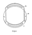
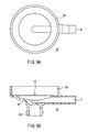
- FIGS. 4 , 5A, and 5B show the structure of the annular holder 9.
- FIG. 4 is a perspective view of the annular holder 9
- FIG. 5A is a plan view of the same
- FIG. 5B is a cross-sectional view of the same along the A-A line in FIG. 5A .
- the annular holder 9 is composed of a cylinder portion 9a and a flange portion 9b.
- the cylinder portion 9a provides an inner space in which the filter 8 is mounted and an inner peripheral surface to which the outer peripheral surface of the filter 8 is bonded.
- the flange portion 9b retains the annular holder 9 when mounting the filter 8 and the annular rib substrate 10, and also provides convenience in handing when mounting the filter structure 12 into the filter retaining portion 3.
- FIGS. 6 , 7A, and 7B show the structure of the annular rib substrate 10.
- FIG. 6 is a perspective view of the annular rib substrate 10
- FIG. 7A is a plan view of the same
- FIG. 7B is a front view of the same.
- the annular rib substrate 10 is composed of an annular portion 10a having a disc shape and a plurality of ribs 10b.
- the plurality of ribs 10b are aligned on a surface of the annular portion 10a, and the ribs 10b forming a pair of upper and lower ribs in FIG. 7A correspond respectively to spaces between the ridgelines 8b of the pleats of the filter 8.
- respective pleat receiving portions 10c formed by gaps between adjacent ribs 10b correspond to the ridgelines 8b of the respective pleats.
- the ridgelines 8b are inserted respectively in the pleat receiving portions 10c.
- the filter structure 12 configured as above is mounted in the filter retaining portion 3 as shown in FIG. 1C , and are bonded together with the bonding resin 11, thereby forming the blood filter device of the present embodiment.
- the pleat gaps 8c are formed in the peripheral region of the filter 8, air bubbles or the like remaining in spaces between the pleats of the filter 8 move upward through the pleat gaps 8c, and are more likely to be removed.
- Blood or a priming solution from the blood inlet 5 flows through the pleat gaps 8c of the peripheral region and flows smoothly between the pleats when passing through the filter 8 of the filter retaining portion 3.
- gaps of the sheet-like filter member 8a are widened by the initial flow, and the pleat gaps are formed even in a central region of the filter 8, thereby widening the channel of the priming solution. Accordingly, if the pleat gaps 8c are formed by the annular substrate 10 in at least a peripheral region of the filter 8, the sufficient function for removing air bubbles remaing or trapped in the filter 8 can be provided.
- annular rib substrate 10 By mounting the annular rib substrate 10 at least on the top surface of the filter 8, a sufficient effect in practical use is obtained. If a pair of the annular rib substrates 10 are mounted respectively on both the top and bottom surfaces of the filter 8, air bubbles can be removed more easily.
- the filter member a mesh material, a woven material, a non-woven material, or the like or a combination thereof can be used.
- the filter member can be made of polyester, polypropylene, polyamide, fluorocarbon fiber, stainless steel or the like.
- the housing 1, especially a horizontal cross section of the dome 2 has a circular shape.
- other shapes such as an ellipse shape also can produce the same effect as described above.
- FIG. 8A is a cross-sectional view of the upper half 1a of the housing constituting the blood filter device, and FIG. 8B is a bottom view of the same.
- FIG. 9A is a plan view of the lower half 1b of the housing, and FIG. 9B is a cross-sectional view of the same.
- a pair of notches 14 are formed on the retaining portion inner cylinder 3a of the upper half 1a of the housing.
- Through holes 15 are formed on the retaining portion outer cylinder 3b of the lower half 1b of the housing, at the positions corresponding to the pair of notches 14 on the retaining portion inner cylinder 3a.
- the notches 14 communicate with the through holes 15, thereby forming holes that pass through peripheral walls of the retaining portion inner and outer cylinders 3a and 3b. These holes are used as resin paths for charging a resin during potting, which will be described below.
- FIGS. 10, 11 , and 12 show processes relating to the manufacture of the filter structure in manufacturing the blood filter device.
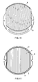
- the filter 8 is mounted in the annular holder 9 as shown in FIG. 10 .
- the auxiliary bonding resin 13 is charged into the space between the outer periphery of the filter 8 and the inner peripheral surface of the annular holder 9 and is hardened, as shown in FIG. 11 .
- the auxiliary bonding resin 13 is charged into each of peripheral portions of the filter 8, thereby the filter 8 is bonded to the annular holder 9.
- FIG. 11 is a view observed from the front side, also in the backside, the auxiliary bonding resin 13 is charged similarly into each of peripheral portions of the filter 8.
- a pair of the annular rib substrates 10 are faced respectively to both the top and the bottom surfaces of the filter 8 as shown in FIG.
- the filter structure 12 in which the filter 8, the annular holder 9, and the annular rib substrates 10 are combined is formed as shown in FIG. 3 .
- the filter structure 12 By forming the filter structure 12 in this way, an operation for inserting respectively the plurality of ribs 10b into the space between the ridgelines of the plurality of pleats can be carried out very easily in the process of mounting the annular rib substrates 10 on the filter 8. This is because, in the process shown in FIG. 11 , the filter 8 is retained in a steady shape by mounting the filter 8 in the annular holder 9, and bonding them with the auxiliary bonding resin 13, and thus the operation for mounting the annular rib substrates 10 can be carried out in that state. As the result, the pleats gaps 8c can be formed surely and easily in the peripheral region of the filter 8.
- the filter structure 12 formed in the above manner is mounted in the retaining portion inner cylinder 3a of the upper half 1a of the housing shown in FIGS. 8A and 8B .
- the retaining portion outer cylinder 3b of the lower half 1b of the housing shown in FIGS. 9A and 9B is fit into the retaining portion inner cylinder 3a, thereby obtaining the housing 1 as a single component.
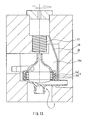
- the housing 1 in which the filter structure 12 is mounted is placed in a device provided with a potting jig as shown in FIG. 13 so as to carry out potting with a sealing resin.
- the device shown in FIG. 13 is composed of a rotating jig 16, a resin reservoir 17, and a resin supply channel 18.
- the rotating jig 18 includes a cavity 16a having a prescribed shape for supporting the housing 1.
- the resin reservoir 17 storing a sealing resin such as a urethane resin is provided at the top of the rotating jig 16, and the resin supply channel 18 is formed from the resin reservoir 17 to a side surface of the filter retaining portion 3.
- the housing 1 rotates together.
- a sealing resin supplied to the side surface of the filter retaining portion 3 enters the cavity of the retaining portion inner cylinder 3a through the notches 14 and the through holes 15 (see FIGS. 8A, 8B , 9A, and 9B ).
- the range for charging with a resin is adjusted on the basis of the inner periphery of the annular rib substrate 10.
- the inner periphery of the annular rib substrate 10 is set to coincide with the diameter of the lower end of the inner peripheral surface of the dome 2 and with the diameter of the upper end of the inner peripheral surface of the bottom portion 4. Accordingly, a channel in the filter 8 defined by the bonding resin 11 continues smoothly from the lower edge of the inner peripheral surface of the dome 2 to the upper end of the inner peripheral surface of the bottom portion 4, and thus an excellent channel condition is obtained.
- the blood filter device of the present invention can remove easily air bubbles remaining or trapped in the filter, it is useful as a component of an artificial heart-lung circuit.
Landscapes
- Health & Medical Sciences (AREA)
- Heart & Thoracic Surgery (AREA)
- Vascular Medicine (AREA)
- Hematology (AREA)
- Animal Behavior & Ethology (AREA)
- Engineering & Computer Science (AREA)
- Anesthesiology (AREA)
- Biomedical Technology (AREA)
- Veterinary Medicine (AREA)
- Life Sciences & Earth Sciences (AREA)
- Public Health (AREA)
- General Health & Medical Sciences (AREA)
- Cardiology (AREA)
- Urology & Nephrology (AREA)
- Chemical & Material Sciences (AREA)
- Chemical Kinetics & Catalysis (AREA)
- Emergency Medicine (AREA)
- External Artificial Organs (AREA)
Abstract
Description
- The present invention relates to a blood filter device used for filtering foreign substances, thrombi, and the like in an artificial heart-lung circuit. In particular, the present invention relates to a blood filter device configured so that air bubbles remaining in a filter can be removed easily and to a method of manufacturing the same.
- In many cases, a blood filter device such as an arterial filter is incorporated in an artificial heart-lung circuit used for heart surgery involving extracorporeal circulation for the sake of safety. To provide security for patients, it has been demanded strongly that such a blood filter device be configured so that it can remove minute foreign substances in the artificial heart-lung circuit, thrombi formed during operation, or air that has entered or been released from the circuit so as not to allow them to enter the patient body.
- A filter generally used in the blood filter device is a polyester screen filter with pores of about 20 to 40 µm that has been pleated and then formed into a cylindrical shape. For example,
Patent Document 1 discloses that a filter sheet is folded so as to have a plurality of pleats and the pleated filter member then is formed into a cylindrical shape in which the respective pleats are arranged radially with peaks thereof positioned on the outer circumference side and valleys thereof positioned on the inner circumference side. The thus-formed cylindrical filter is disposed in a cylindrical housing. In the filter configured as above, blood flows in the housing in the radial direction of the cylindrical filter member to pass therethrough, which allows therethrough, which allows dirt, impurities, thrombi, and the like contained in the blood to be removed effectively. - In the filter as described above, blood first flows into an upper part of the cylindrical filter member, passes through the cylindrical filter member in its radial direction via an outer part of the filter member, and then flows out from a lower part of the cylindrical filter member via an inner part of the filter member. In this filter, the filter member surface extends vertically. This poses a problem in that, when a priming solution flows into the filter surface during a priming operation, air bubbles are liable to remain in the filter. Moreover, it is difficult to discharge the remaining air bubbles to the outside. This is because, since the filter member surface extends vertically, the air bubbles cannot be released from the filter easily, so that it takes quite a long time to remove the air bubbles completely.
- More specifically, air bubbles remaining in the filter can be released with an impact from the outside caused by, for instance, flicking the housing with a finger. In this case, however, although the air bubbles can be released temporarily by giving an impact from a portion close to a position where the air bubbles adhere, they are liable to adhere again to an adjacent pleat of the filter. Thus, it is difficult to bring the air bubbles to an air vent provided above.
-
Patent Document 2 describes a blood filter device that solves such problems, and it is configured so that impurities, thrombi, and the like in blood can be removed effectively, and air bubbles remaining in a filter also can be removed easily. - The blood filter device described in
Patent Document 2 includes a housing that includes a dome provided with a blood inlet and an air vent at the top of the dome, a filter retaining portion disposed below the dome, and a bottom portion that is disposed below the filter retaining portion and is provided with a blood outlet. Blood that has flowed into the dome from the inlet passes through the filter retaining portion, and flows out from the outlet. A filter is disposed in the filter retaining portion so as to partition a cavity of the housing into a dome side and a bottom portion side. The filter is formed of a sheet-like filter member folded to have a plurality of pleats, and it is disposed so that ridgelines of the plurality of pleats traverse respectively the cavity of the filter retaining portion in parallel. - According to this configuration, foreign substances, thrombi, and the like in blood can be removed reliably, and since there are no obstacles in the vertical direction of the filter, air bubbles adhered onto the top face of the filter during a priming operation can be removed easily by only applying a physical impact to the housing.
- Patent Document 1: Japanese Patent No.
3270193 - Patent Document 2:
WO2004/084974 - As described above, it is desirable that the filter shaped by arranging a plurality of pleats in parallel is retained in the filter retaining portion in the state where there is a certain gap between adjacent pleats. When the pleats are in contact with each other, and there is no gap therebetween, a blocked space is formed at the bottom of a valley between the pleats. Therefore, if air bubbles remaining in or air bubbles formed at another places get trapped in the blocked space, it is difficult to remove the air bubbles even by applying a physical impact to the housing.
- However, it is also difficult to fix the filter in the cavity of the filter retaining portion while maintaining a gap between adjacent pleats. That is, when disposing the filter that is folded to have pleats in the filter retaining portion, the pleats bulge because the sheet-like filter member forming the filter is in a free state. Thus, adjacent pleats are liable to be in contact with each other. This can be a problem especially when the efficiency of filtering is to be increased without increasing the size of the housing of the filter. That is, if the pleats are heightened and pitches are reduced to increase the area of a filter film, the pleats are liable to be in contact with each other with their natural bulges.
- With forgoing in mind, it is an object of the present invention to provide a blood filter device configured so that gaps between a plurality of pleats of a sheet-like filter member forming a filter are ensured to remove air bubbles easily.
- A blood filter device of the present invention includes: a housing including a dome that is provided with a blood inlet and forms an upper part of the housing, a filter retaining portion that is positioned below the dome and forms a middle part of the housing, and a bottom portion that is disposed below the filter retaining portion and is provided with a blood outlet; and a filter that is disposed in a cavity of the filter retaining portion and partitions a cavity of the housing into a dome side and a bottom portion side. The filter is formed of a sheet-like filter member folded to have a plurality of pleats, and is disposed so that ridgelines of the plurality of pleats traverse respectively the cavity of the filter retaining portion in parallel.
- In order to solve the above problems, the blood filter device of the present invention includes: an annular holder disposed to intervene between an inner peripheral surface of the filter retaining portion and an outer peripheral surface of the filter; an annular rib substrate, which is an annular member disposed facing the ridgelines of the plurality of pleats in an outer peripheral region of the filter and is provided with a plurality of ribs that are inserted respectively between the ridgelines of the plurality of pleats; and a bonding resin that is charged in an outer peripheral portion of the filter including the annular holder and the annular rib substrate and bonds the outer peripheral portion of the filter to the filter retaining portion.
- In order to manufacture the blood filter device as described above, a method of manufacturing the blood filter device of the present invention includes steps of: mounting the filter in an annular holder formed so as to intervene between an inner peripheral surface of the filter retaining portion and an outer peripheral surface of the filter, so that the outer peripheral surface of the filter faces the inner peripheral surface of the annular holder; mounting an annular rib substrate, which is an annular member having a shape and a size to face ridgelines of the plurality of pleats in an outer peripheral region of the filter and is provided with a plurality of ribs that can be inserted respectively between the ridgelines of the plurality of pleats, on the filter so as to insert respectively the plurality of ribs between the ridgelines of the plurality of pleats and forming a filter structure in which the filter, the annular holder, and the annular rib substrates are combined; placing the filter structure in a cavity of the filter retaining portion and mounting thereof in the housing; and charging a bonding resin into an outer peripheral portion of the filter including the annular holder and the annular rib substrate and hardening the bonding resin to bond the filter to the filter retaining portion with the bonding resin.
- According to the blood filter device configured as above, since the plurality of ribs provided on the annular rib substrate are inserted respectively between the ridgelines of the plurality of pleats, gaps between the plurality of pleats of the filter are ensured. As the result, air bubbles remaining in the filter or air bubbles trapped in the filter are removed easily.
-
- [
FIG. 1A] FIG. 1A is a front view of a blood filter device according to an embodiment of the present invention. - [
FIG. 1B] FIG. 1B is a plan view of the blood filter device. - [
FIG. 1C] FIG. 1C is a cross-sectional view of the blood filter device. - [
FIG. 2] FIG. 2 is a perspective view of a filter constituting the blood filter device. - [
FIG. 3] FIG. 3 is a perspective view of a filter structure constituting the blood filter device. - [
FIG. 4] FIG. 4 is a perspective view of an annular holder constituting the blood filter device. - [
FIG. 5A] FIG. 5A is a plan view of the annular holder. - [
FIG. 5B] FIG. 5B is a cross-sectional view of the annular holder. - [
FIG. 6] FIG. 6 is a perspective view of an annular rib substrate constituting the blood filter device. - [
FIG. 7A] FIG. 7A is a plan view of the annular rib substrate. - [
FIG. 7B] FIG. 7B is a front view of the annular rib substrate. - [
FIG. 8A] FIG. 8A is a cross-sectional view of an upper half of housing constituting the blood filter device. - [
FIG. 8B] FIG. 8B is a bottom view of the upper half of the housing. - [
FIG. 9A] FIG. 9A is a plan view of a lower half of the housing. - [
FIG. 9B] FIG. 9B is a cross-sectional view of the lower half of the housing. - [
FIG. 10] FIG. 10 is a perspective view showing a process in a method of manufacturing the blood filter device according to an embodiment of the present invention. - [
FIG. 11] FIG. 11 is a plan view showing another process in the manufacturing method. - [
FIG. 12] FIG. 12 is a perspective view showing yet another process in the manufacturing method. - [
FIG. 13] FIG. 13 is a cross-sectional view showing a device used in potting in the manufacturing method. -
- 1
- housing
- 1a
- upper half of housing
- 1b
- lower half of housing
- 2
- dome
- 3
- filter retaining portion
- 3a
- retaining portion inner cylinder
- 3b
- retaining portion outer cylinder
- 4
- bottom portion
- 4a
- support portion
- 5
- blood inlet
- 6
- air vent
- 7
- blood outlet
- 8
- filter
- 8a
- sheet-like filter member
- 8b
- pleat
- 8c
- pleat gap
- 9
- annular holder
- 9a
- cylinder portion
- 9b
- flange portion
- 10
- annular rib substrate
- 10a
- annular portion
- 10b
- rib
- 10c
- pleat receiving portion
- 11
- bonding resin
- 12
- filter structure
- 13
- auxiliary bonding resin
- 14
- notch
- 15
- through hole
- 16
- rotating jig
- 16a
- cavity
- 17
- resin reservoir
- 18
- resin supply channel
- In the blood filter device of the present invention, it is preferable that an outer periphery of the filter is bonded to an inner peripheral surface of the annular holder with an auxiliary bonding resin, and it is further bonded to the filter retaining portion with the bonding resin.
- Further, it is preferable that the blood filter device of the present invention includes a pair of the annular rib substrates, and the annular rib substrates are disposed facing the ridgelines of the plurality of pleats on both top and bottom surfaces of the filter respectively.
- In the method of manufacturing the blood filter device of the present invention, it is preferable that after mounting the filter in the annular holder, an auxiliary resin is charged into outer peripheral portions of the filter so as to retain the outer peripheral portion of the filter to the inner peripheral surface of the annular holder with the auxiliary bonding resin.
- Furthermore, it is preferable that after mounting the filter structure in the housing, the bonding resin is charged into an outer peripheral region of the filter including the annular holder and the annular rib substrates while applying a centrifugal force about the central axis of the cavity of the filter holder.
- Hereinafter, a blood filter device according to an embodiment of the present invention will be described with reference to the drawings.
-
FIG. 1A is a front view of the blood filter device,FIG. 1B is a plan view of the same, andFIG. 1C is a cross-sectional view of the same. Ahousing 1 is made of resin for example, and it includes adome 2 forming an upper part of the housing, afilter retaining portion 3 forming a middle part of the housing, and abottom portion 4 forming a lower part of the housing. Thehousing 1 has a horizontal cross section of a circular shape. - On a lateral portion of the
dome 2, ablood inlet 5 is provided so as to allow blood to flow into thedome 2 horizontally and along an inner wall of thedome 2. On the top of thedome 2, anair vent 6 for discharging air such as air bubbles is provided. Ablood outlet 7 is provided on thebottom portion 4. Afilter retaining portion 3 has a cylindrical shape. As shown inFIG. 1C , afilter 8 for filtering foreign substances in blood is disposed in thefilter retaining portion 3. Thefilter 8 partitions a cavity of thehousing 1 into adome 2 side and abottom portion 4 side. Liquid that has flowed into thedome 2 from theblood inlet 5 passes through thefilter retaining portion 3 and then flows out from theblood outlet 7. Thebottom portion 4 also has asupport portion 4a, which is used when installing the filter device and is irrelevant to the filtering function. - The
dome 2 is formed so that an inner diameter thereof is reduced gradually toward the top of thedome 2. This allows air bubbles to be gathered and released to move upward along the inner peripheral surface of thedome 2. Thedome 2 has a circular cross section, and is provided with theblood inlet 5 so as to allow blood flow into the dome horizontally and along an inner wall of thedome 2. The blood that has flowed in from theblood inlet 5 flows downwards, and then flows into thefilter retaining portion 3. The shape of thedome 2 is not limited to that shown inFIG. 1A etc. as long as it is formed so that an outer diameter thereof is reduced toward theair vent 6. For instance, it may have a conical shape or a funnel shape. - As shown in
FIG. 1C , thehousing 1 is composed of anupper half 1a and alower half 1b of the housing. Thefilter retaining portion 3 is composed of a retaining portioninner cylinder 3a and a retaining portionouter cylinder 3b formed in theupper half 1a and thelower half 1b of the housing respectively. Theupper half 1a and thelower half 1b of the housing are joined together by fitting the retaining portionouter cylinder 3b into the retaining portioninner cylinder 3a, thereby obtaining thehousing 1 as a single component. - As schematically shown in
FIG. 2 , thefilter 8 is formed of a sheet-like filter member 8a made of a sheet-like mesh material folded so as to form a plurality of pleats. Thefilter 8 is disposed so thatridgelines 8b of the plurality of pleats traverse respectively a cavity of the retaining portioninner cylinder 3a (filter retaining portion 3) in parallel. That is, theridgelines 8b of the respective pleats are parallel to the direction of theblood inlet 5 or theblood outlet 7, and is oriented in the direction along a chord of the retaining portioninner cylinder 3a. An enveloping surface of theridgelines 8b of the respective pleats is flat, and thus thefilter 8 as a whole has a flat outer shape. By disposing theridgelines 8b of the respective pleats in parallel to the direction of theblood inlet 5 or theblood outlet 7, a flow of blood or a priming solution becomes parallel to theridgelines 8b of the pleats, thereby those solutions flow easily into spaces between the pleats. As the result, removal of air bubbles is ensured. - As shown in
FIG. 1C , theannular holder 9 is disposed to intervene between an inner peripheral surface of thefilter retaining portion 3 and an outer peripheral surface of thefilter 8. Anannular rib substrate 10 is disposed facing theridgelines 8b of the plurality of pleats of thefilter 8 in an outer peripheral region of thefilter 8. As will be described below, theannular rib substrate 10 has a plurality of ribs (not shown inFIG. 1C ) that are inserted respectively between the ridgelines 8b of the plurality of pleats. Abonding resin 11 is charged into an outer peripheral portion of thefilter 8 including theannular holder 9 and theannular rib substrate 10. Thefilter 8 is bonded to the inner peripheral surface of theannular holder 9 with an auxiliary boding resin (not shown), and it is bonded further to the inner peripheral surface of thefilter retaining portion 3, namely the inner peripheral surface of the retaining portioninner cylinder 3a, with thebonding resin 11. -
FIG. 3 shows afilter structure 12 in which thefilter 8, theannular holder 9, and theannular rib substrate 10 are combined. The outer periphery of thefilter 8 is bonded to the inner peripheral surface of theannular holder 9 with anauxiliary bonding resin 13. -
FIGS. 4 ,5A, and 5B show the structure of theannular holder 9.FIG. 4 is a perspective view of theannular holder 9,FIG. 5A is a plan view of the same, andFIG. 5B is a cross-sectional view of the same along the A-A line inFIG. 5A . Theannular holder 9 is composed of acylinder portion 9a and aflange portion 9b. Thecylinder portion 9a provides an inner space in which thefilter 8 is mounted and an inner peripheral surface to which the outer peripheral surface of thefilter 8 is bonded. Theflange portion 9b retains theannular holder 9 when mounting thefilter 8 and theannular rib substrate 10, and also provides convenience in handing when mounting thefilter structure 12 into thefilter retaining portion 3. -
FIGS. 6 ,7A, and 7B show the structure of theannular rib substrate 10.FIG. 6 is a perspective view of theannular rib substrate 10,FIG. 7A is a plan view of the same, andFIG. 7B is a front view of the same. Theannular rib substrate 10 is composed of anannular portion 10a having a disc shape and a plurality ofribs 10b. The plurality ofribs 10b are aligned on a surface of theannular portion 10a, and theribs 10b forming a pair of upper and lower ribs inFIG. 7A correspond respectively to spaces between the ridgelines 8b of the pleats of thefilter 8. Thus, respectivepleat receiving portions 10c formed by gaps betweenadjacent ribs 10b correspond to theridgelines 8b of the respective pleats. In thefilter structure 12 shown inFIG. 3 , theridgelines 8b are inserted respectively in thepleat receiving portions 10c. - As shown in
FIG. 3 , by mounting theannular rib substrate 10, in the outer peripheral region of thefilter 8, gaps of the sheet-like filter member 8a forming the respective pleats are widened by theribs 10b, thereby formingpleat gaps 8c. - The
filter structure 12 configured as above is mounted in thefilter retaining portion 3 as shown inFIG. 1C , and are bonded together with thebonding resin 11, thereby forming the blood filter device of the present embodiment. - In the blood filter device of the present invention configured as above, since the
pleat gaps 8c are formed in the peripheral region of thefilter 8, air bubbles or the like remaining in spaces between the pleats of thefilter 8 move upward through thepleat gaps 8c, and are more likely to be removed. Blood or a priming solution from theblood inlet 5 flows through thepleat gaps 8c of the peripheral region and flows smoothly between the pleats when passing through thefilter 8 of thefilter retaining portion 3. By this flow, air bubbles are removed easily. Furthermore, in some cases, gaps of the sheet-like filter member 8a are widened by the initial flow, and the pleat gaps are formed even in a central region of thefilter 8, thereby widening the channel of the priming solution. Accordingly, if thepleat gaps 8c are formed by theannular substrate 10 in at least a peripheral region of thefilter 8, the sufficient function for removing air bubbles remaing or trapped in thefilter 8 can be provided. - By mounting the
annular rib substrate 10 at least on the top surface of thefilter 8, a sufficient effect in practical use is obtained. If a pair of theannular rib substrates 10 are mounted respectively on both the top and bottom surfaces of thefilter 8, air bubbles can be removed more easily. - As the filter member, a mesh material, a woven material, a non-woven material, or the like or a combination thereof can be used. The filter member can be made of polyester, polypropylene, polyamide, fluorocarbon fiber, stainless steel or the like.
- It is preferable that the
housing 1, especially a horizontal cross section of thedome 2, has a circular shape. However, it is to be noted here that other shapes such as an ellipse shape also can produce the same effect as described above. - Next, a method of manufacturing the blood filter device according to the present embodiment will be described.
FIG. 8A is a cross-sectional view of theupper half 1a of the housing constituting the blood filter device, andFIG. 8B is a bottom view of the same.FIG. 9A is a plan view of thelower half 1b of the housing, andFIG. 9B is a cross-sectional view of the same. - The basic configuration is as described with reference to
FIGS. 1A-1C . A pair ofnotches 14 are formed on the retaining portioninner cylinder 3a of theupper half 1a of the housing. Throughholes 15 are formed on the retaining portionouter cylinder 3b of thelower half 1b of the housing, at the positions corresponding to the pair ofnotches 14 on the retaining portioninner cylinder 3a. When theupper half 1a of the housing is fit into thelower half 1b of the housing, thenotches 14 communicate with the throughholes 15, thereby forming holes that pass through peripheral walls of the retaining portion inner andouter cylinders -
FIGS. 10, 11 , and12 show processes relating to the manufacture of the filter structure in manufacturing the blood filter device. - First, the
filter 8 is mounted in theannular holder 9 as shown inFIG. 10 . Then, theauxiliary bonding resin 13 is charged into the space between the outer periphery of thefilter 8 and the inner peripheral surface of theannular holder 9 and is hardened, as shown inFIG. 11 . As shown in the figures, theauxiliary bonding resin 13 is charged into each of peripheral portions of thefilter 8, thereby thefilter 8 is bonded to theannular holder 9. ThoughFIG. 11 is a view observed from the front side, also in the backside, theauxiliary bonding resin 13 is charged similarly into each of peripheral portions of thefilter 8. Subsequently, a pair of theannular rib substrates 10 are faced respectively to both the top and the bottom surfaces of thefilter 8 as shown inFIG. 12 , and are mounted thereon so that the plurality ofribs 10b are inserted respectively between the ridgelines of the plurality of pleats of thefilter 8. As the result, thefilter structure 12 in which thefilter 8, theannular holder 9, and theannular rib substrates 10 are combined is formed as shown inFIG. 3 . - By forming the
filter structure 12 in this way, an operation for inserting respectively the plurality ofribs 10b into the space between the ridgelines of the plurality of pleats can be carried out very easily in the process of mounting theannular rib substrates 10 on thefilter 8. This is because, in the process shown inFIG. 11 , thefilter 8 is retained in a steady shape by mounting thefilter 8 in theannular holder 9, and bonding them with theauxiliary bonding resin 13, and thus the operation for mounting theannular rib substrates 10 can be carried out in that state. As the result, thepleats gaps 8c can be formed surely and easily in the peripheral region of thefilter 8. - Next, in order to manufacture the blood filter device, the
filter structure 12 formed in the above manner is mounted in the retaining portioninner cylinder 3a of theupper half 1a of the housing shown inFIGS. 8A and 8B . Then, the retaining portionouter cylinder 3b of thelower half 1b of the housing shown inFIGS. 9A and 9B is fit into the retaining portioninner cylinder 3a, thereby obtaining thehousing 1 as a single component. Subsequently, thehousing 1 in which thefilter structure 12 is mounted is placed in a device provided with a potting jig as shown inFIG. 13 so as to carry out potting with a sealing resin. - The device shown in
FIG. 13 is composed of arotating jig 16, aresin reservoir 17, and aresin supply channel 18. The rotatingjig 18 includes acavity 16a having a prescribed shape for supporting thehousing 1. Theresin reservoir 17 storing a sealing resin such as a urethane resin is provided at the top of therotating jig 16, and theresin supply channel 18 is formed from theresin reservoir 17 to a side surface of thefilter retaining portion 3. By placing thehousing 1 in therotating jig 16 and rotating therotating jig 16, thehousing 1 rotates together. A sealing resin supplied to the side surface of thefilter retaining portion 3 enters the cavity of the retaining portioninner cylinder 3a through thenotches 14 and the through holes 15 (seeFIGS. 8A, 8B ,9A, and 9B ). - When the
rotating jig 16 is rotated, horizontal centrifugal force about the central axis of thefilter retaining portion 3a acts. As a result, the sealing resin spills out of theresin reservoir 17 so as to be supplied to the retaining portioninner cylinder 3a through theresin supply channel 18, so that the resin is charged into the gap between the inner peripheral surface of the retaining portioninner cylinder 3a and an outer peripheral portion of thefilter 8. By hardening the charged resin, thefilter 8, theannular holder 9, and theannular rib substrates 10 can be retained to the inner peripheral surface of the retaining portioninner cylinder 3a as shown inFIG. 1C . - The range for charging with a resin is adjusted on the basis of the inner periphery of the
annular rib substrate 10. The inner periphery of theannular rib substrate 10 is set to coincide with the diameter of the lower end of the inner peripheral surface of thedome 2 and with the diameter of the upper end of the inner peripheral surface of thebottom portion 4. Accordingly, a channel in thefilter 8 defined by thebonding resin 11 continues smoothly from the lower edge of the inner peripheral surface of thedome 2 to the upper end of the inner peripheral surface of thebottom portion 4, and thus an excellent channel condition is obtained. Industrial Applicability - Since the blood filter device of the present invention can remove easily air bubbles remaining or trapped in the filter, it is useful as a component of an artificial heart-lung circuit.
Claims (6)
- A blood filter device comprising:a housing that includes a dome provided with a blood inlet and forming an upper part of the housing, a filter retaining portion positioned below the dome and forming a middle part of the housing, and a bottom portion disposed below the filter retaining portion and provided with a blood outlet; anda filter mounted in a cavity of the filter retaining portion and partitioning a cavity of the housing into a dome side and a bottom portion side,the filter formed of a sheet-like filter member folded to have a plurality of pleats, and disposed so that ridgelines of the plurality of pleats traverse respectively the cavity of the filter retaining portion in parallel,wherein the blood filter device comprises:an annular holder disposed to intervene between an inner peripheral surface of the filter retaining portion and an outer peripheral surface of the filter;an annular rib substrate, which is an annular member disposed facing the ridgelines of the plurality of pleats in an outer peripheral region of the filter and is provided with a plurality of ribs inserted respectively between the ridgelines of the plurality of pleats; anda bonding resin that is charged into outer peripheral portions of the filter including the annular holder and the annular rib substrate and bonds the outer peripheral portion of the filter to the filter retaining portion.
- The blood filter device according to claim 1, wherein an outer periphery of the filter is bonded to an inner peripheral surface of the annular holder with an auxiliary bonding resin, and is bonded further to the filter retaining portion with the bonding resin.
- The blood filter device according to claim 1 comprising a pair of the annular rib substrates, wherein the annular rib substrates are disposed respectively facing the ridgelines of the plurality of pleats of top and bottom surfaces of the filter.
- A method of manufacturing a blood filter device,
the blood filter comprising: a housing that includes a dome provided with a blood inlet and forming an upper part of the housing, a filter retaining portion positioned below the dome and forming a middle part of the housing, and a bottom portion disposed below the filter retaining portion and provided with a blood outlet; and
a filter mounted in a cavity of the filter retaining portion and partitioning a cavity of the housing into a dome side and a bottom portion side,
the filter being formed of a sheet-like filter member folded to have a plurality of pleats, and disposed so that ridgelines of the plurality of pleats transverse respectively the cavity of the filter retaining portion in parallel, the method including steps of:mounting the filter in an annular holder formed so as to intervene between an inner peripheral surface of the filter retaining portion and an outer peripheral surface of the filter, so that the outer peripheral surface of the filter faces the inner peripheral surface of the annular holder;mounting an annular rib substrate, which is an annular member having a shape and a size to face ridgelines of the plurality of pleats in an outer peripheral region of the filter and is provided with a plurality of ribs that can be inserted respectively between the ridgelines of the plurality of pleats, on the filter so as to insert respectively the plurality of ribs between the ridgelines of the plurality of pleats and forming a filter structure in which the filter, the annular holder, and the annular rib substrates are combined;placing the filter structure in a cavity of the filter retaining portion and mounting thereof in the housing; andcharging a bonding resin into an outer peripheral portion of the filter including the annular holder and the annular rib substrate and hardening the bonding resin so as to bond the filter to the filter retaining portion with the bonding resin. - The method of manufacturing the blood filter device according to claim 1, wherein, after the step of mounting the filter in the annular holder, an auxiliary bonding resin is charged into outer peripheral portions of the filter so as to bond outer peripheral portions of the filter to an inner peripheral surface of the annular holder with the auxiliary bonding resin.
- The method of manufacturing the blood filter device according to claim 4 or 5, wherein, after the step of mounting the filter structure in the housing, the bonding resin is charged into an outer peripheral region of the filter including the annular holder and the annular rib substrate while applying a centrifugal force about a central axis of the cavity of the filter holding portion.
Applications Claiming Priority (2)
| Application Number | Priority Date | Filing Date | Title |
|---|---|---|---|
| JP2005291205A JP4792904B2 (en) | 2005-10-04 | 2005-10-04 | Blood filter device and manufacturing method thereof |
| PCT/JP2006/314776 WO2007039977A1 (en) | 2005-10-04 | 2006-07-26 | Blood filter device and method of manufacturing the same |
Publications (3)
| Publication Number | Publication Date |
|---|---|
| EP1941920A1 true EP1941920A1 (en) | 2008-07-09 |
| EP1941920A4 EP1941920A4 (en) | 2013-01-02 |
| EP1941920B1 EP1941920B1 (en) | 2015-08-19 |
Family
ID=37906023
Family Applications (1)
| Application Number | Title | Priority Date | Filing Date |
|---|---|---|---|
| EP06781688.4A Not-in-force EP1941920B1 (en) | 2005-10-04 | 2006-07-26 | Blood filter device and method of manufacturing the same |
Country Status (7)
| Country | Link |
|---|---|
| US (1) | US8162152B2 (en) |
| EP (1) | EP1941920B1 (en) |
| JP (1) | JP4792904B2 (en) |
| KR (1) | KR100934084B1 (en) |
| CN (1) | CN101282750B (en) |
| CA (1) | CA2624828C (en) |
| WO (1) | WO2007039977A1 (en) |
Cited By (1)
| Publication number | Priority date | Publication date | Assignee | Title |
|---|---|---|---|---|
| US20100258357A1 (en) * | 2009-04-10 | 2010-10-14 | Sierra Instruments | Inertial Microbalance Filter Assembly |
Families Citing this family (18)
| Publication number | Priority date | Publication date | Assignee | Title |
|---|---|---|---|---|
| WO2004084974A1 (en) * | 2003-03-24 | 2004-10-07 | Jms Co. Ltd. | Blood filter device and method of producing the same |
| TWI461230B (en) * | 2010-10-07 | 2014-11-21 | Univ Nat Cheng Kung | Filtration film for filtrating the blood serum and method for manufacturing the same and filtration device |
| JP5857574B2 (en) * | 2011-09-17 | 2016-02-10 | 株式会社ジェイ・エム・エス | Blood filter device and blood filter device manufacturing method |
| JP6101356B2 (en) | 2013-10-03 | 2017-03-22 | 旭化成メディカル株式会社 | Blood processing filter and method for manufacturing blood processing filter |
| CN106029965B (en) | 2014-02-17 | 2018-04-03 | 3M创新有限公司 | Clean product and preparation and application |
| JP6263062B2 (en) * | 2014-03-25 | 2018-01-17 | 旭化成メディカル株式会社 | Resin panel circuit and manufacturing method thereof |
| JP6368369B2 (en) * | 2014-07-07 | 2018-08-01 | 旭化成メディカル株式会社 | Blood processing filter and method for manufacturing blood processing filter |
| CN106215265B (en) * | 2016-08-16 | 2018-09-11 | 珠海健帆生物科技股份有限公司 | Blood purification method for exhausting |
| CN114728109A (en) * | 2019-11-12 | 2022-07-08 | 费森尤斯医疗护理德国有限责任公司 | Blood treatment system |
| CN114728117B (en) | 2019-11-12 | 2025-11-11 | 费森尤斯医疗护理德国有限责任公司 | Blood therapy system |
| CA3160952A1 (en) | 2019-11-12 | 2021-05-20 | Fresenius Medical Care Deutschland Gmbh | Blood treatment systems |
| CN114728159B (en) | 2019-11-12 | 2025-10-17 | 费森尤斯医疗护理德国有限责任公司 | Blood treatment system |
| CA3160850A1 (en) | 2019-11-12 | 2021-05-20 | Fresenius Medical Care Deutschland Gmbh | Blood treatment systems |
| CN114728110A (en) | 2019-11-12 | 2022-07-08 | 费森尤斯医疗护理德国有限责任公司 | Blood treatment system |
| WO2021096706A1 (en) | 2019-11-12 | 2021-05-20 | Fresenius Medical Care Deutschland Gmbh | Blood treatment systems |
| CN115315280A (en) | 2019-12-12 | 2022-11-08 | 费森尤斯医疗保健控股公司 | Blood treatment system |
| JP7643008B2 (en) * | 2020-10-21 | 2025-03-11 | 株式会社ジェイ・エム・エス | Filter Device |
| KR102871638B1 (en) * | 2023-02-27 | 2025-10-15 | 인제대학교 산학협력단 | Suction system having pneumoperitoneum maintain function |
Family Cites Families (17)
| Publication number | Priority date | Publication date | Assignee | Title |
|---|---|---|---|---|
| DE2135813B2 (en) * | 1971-07-17 | 1975-07-10 | Draegerwerk Ag, 2400 Luebeck | HEPA filter insert for breathing apparatus made from a folded filter sheet |
| JPS5795233U (en) * | 1980-12-01 | 1982-06-11 | ||
| JPS5795223A (en) | 1980-12-05 | 1982-06-14 | Japanese National Railways<Jnr> | L-shaped rigid-body trolley wire device |
| US5178760A (en) | 1989-04-06 | 1993-01-12 | Solberg Mfg. Co. | Fluid filter construction with a corrugated and tapered filter strip |
| JPH03270193A (en) | 1990-03-20 | 1991-12-02 | Fujitsu Ltd | Method of manufacturing printed board |
| JPH04310202A (en) * | 1991-04-08 | 1992-11-02 | Toyo Roki Seizo Kk | Filter element and manufacture thereof |
| CA2061454C (en) * | 1991-02-19 | 2000-08-01 | Teruichi Kadoya | Filter element and method for producing the same |
| US5618425A (en) * | 1993-04-30 | 1997-04-08 | Terumo Kabushiki Kaisha | Filtering apparatus with a pleated filtering element embedded in a filling material |
| JP3270193B2 (en) | 1993-04-30 | 2002-04-02 | テルモ株式会社 | Filtration device |
| US5651765A (en) | 1995-04-27 | 1997-07-29 | Avecor Cardiovascular Inc. | Blood filter with concentric pleats and method of use |
| DE19636006A1 (en) * | 1996-09-05 | 1998-03-12 | Sartorius Gmbh | Filtration unit with pleated filter elements |
| US6143174A (en) * | 1996-09-05 | 2000-11-07 | Sartorius Ag | Filtration unit with pleated filtering elements |
| US6074450A (en) * | 1996-10-15 | 2000-06-13 | Raber; Robert R. | Air filter assembly |
| JPH10211411A (en) * | 1997-01-29 | 1998-08-11 | Japan Vilene Co Ltd | filter |
| US6319300B1 (en) * | 2000-07-12 | 2001-11-20 | Liou-Win Chen | Filter assembly of an air filter |
| US8027721B2 (en) * | 2003-03-24 | 2011-09-27 | Physio-Control, Inc. | Balanced charge waveform for transcutaneous pacing |
| WO2004084974A1 (en) * | 2003-03-24 | 2004-10-07 | Jms Co. Ltd. | Blood filter device and method of producing the same |
-
2005
- 2005-10-04 JP JP2005291205A patent/JP4792904B2/en not_active Expired - Lifetime
-
2006
- 2006-07-26 CA CA2624828A patent/CA2624828C/en not_active Expired - Fee Related
- 2006-07-26 US US12/083,139 patent/US8162152B2/en not_active Expired - Fee Related
- 2006-07-26 WO PCT/JP2006/314776 patent/WO2007039977A1/en not_active Ceased
- 2006-07-26 CN CN2006800370290A patent/CN101282750B/en active Active
- 2006-07-26 KR KR1020087007877A patent/KR100934084B1/en not_active Expired - Fee Related
- 2006-07-26 EP EP06781688.4A patent/EP1941920B1/en not_active Not-in-force
Cited By (2)
| Publication number | Priority date | Publication date | Assignee | Title |
|---|---|---|---|---|
| US20100258357A1 (en) * | 2009-04-10 | 2010-10-14 | Sierra Instruments | Inertial Microbalance Filter Assembly |
| US8563879B2 (en) * | 2009-04-10 | 2013-10-22 | Sierra Instruments | Inertial microbalance filter assembly |
Also Published As
| Publication number | Publication date |
|---|---|
| CN101282750B (en) | 2010-10-27 |
| WO2007039977A1 (en) | 2007-04-12 |
| JP2007097818A (en) | 2007-04-19 |
| US8162152B2 (en) | 2012-04-24 |
| EP1941920A4 (en) | 2013-01-02 |
| US20090045131A1 (en) | 2009-02-19 |
| CA2624828A1 (en) | 2007-04-12 |
| JP4792904B2 (en) | 2011-10-12 |
| HK1119096A1 (en) | 2009-02-27 |
| EP1941920B1 (en) | 2015-08-19 |
| CN101282750A (en) | 2008-10-08 |
| CA2624828C (en) | 2011-11-22 |
| KR20080042917A (en) | 2008-05-15 |
| KR100934084B1 (en) | 2009-12-24 |
Similar Documents
| Publication | Publication Date | Title |
|---|---|---|
| EP1941920B1 (en) | Blood filter device and method of manufacturing the same | |
| US20100163163A1 (en) | Blood filter device and method of producing the same | |
| CA2230590C (en) | An in-line blood filtration device | |
| CN110430904B (en) | Blood separation method and blood separation filter | |
| US5618425A (en) | Filtering apparatus with a pleated filtering element embedded in a filling material | |
| KR101299458B1 (en) | Frameless, plate-shaped filtering member | |
| JP4500776B2 (en) | Artificial lung | |
| EP1982738B1 (en) | Blood filter device | |
| JP4168347B2 (en) | Blood filter device and manufacturing method thereof | |
| HK1119096B (en) | Blood filter device and method of manufacturing the same | |
| HK1088568B (en) | Blood filter device and method for producing the same | |
| JP5857574B2 (en) | Blood filter device and blood filter device manufacturing method | |
| EP3498314A1 (en) | Blood treatment instrument | |
| HK1126434B (en) | Blood filter device and method of producing the same |
Legal Events
| Date | Code | Title | Description |
|---|---|---|---|
| PUAI | Public reference made under article 153(3) epc to a published international application that has entered the european phase |
Free format text: ORIGINAL CODE: 0009012 |
|
| 17P | Request for examination filed |
Effective date: 20080418 |
|
| AK | Designated contracting states |
Kind code of ref document: A1 Designated state(s): AT BE BG CH CY CZ DE DK EE ES FI FR GB GR HU IE IS IT LI LT LU LV MC NL PL PT RO SE SI SK TR |
|
| DAX | Request for extension of the european patent (deleted) | ||
| A4 | Supplementary search report drawn up and despatched |
Effective date: 20121203 |
|
| RIC1 | Information provided on ipc code assigned before grant |
Ipc: A61M 1/34 20060101AFI20121127BHEP Ipc: A61M 1/36 20060101ALI20121127BHEP |
|
| GRAP | Despatch of communication of intention to grant a patent |
Free format text: ORIGINAL CODE: EPIDOSNIGR1 |
|
| INTG | Intention to grant announced |
Effective date: 20150326 |
|
| RIN1 | Information on inventor provided before grant (corrected) |
Inventor name: OMORI, MASAYOSHI Inventor name: NAKAO, SHOTA Inventor name: KATSUNO, YUTAKA |
|
| GRAS | Grant fee paid |
Free format text: ORIGINAL CODE: EPIDOSNIGR3 |
|
| GRAA | (expected) grant |
Free format text: ORIGINAL CODE: 0009210 |
|
| AK | Designated contracting states |
Kind code of ref document: B1 Designated state(s): AT BE BG CH CY CZ DE DK EE ES FI FR GB GR HU IE IS IT LI LT LU LV MC NL PL PT RO SE SI SK TR |
|
| REG | Reference to a national code |
Ref country code: GB Ref legal event code: FG4D |
|
| REG | Reference to a national code |
Ref country code: CH Ref legal event code: EP |
|
| REG | Reference to a national code |
Ref country code: IE Ref legal event code: FG4D |
|
| REG | Reference to a national code |
Ref country code: AT Ref legal event code: REF Ref document number: 743341 Country of ref document: AT Kind code of ref document: T Effective date: 20150915 |
|
| REG | Reference to a national code |
Ref country code: DE Ref legal event code: R096 Ref document number: 602006046351 Country of ref document: DE |
|
| REG | Reference to a national code |
Ref country code: AT Ref legal event code: MK05 Ref document number: 743341 Country of ref document: AT Kind code of ref document: T Effective date: 20150819 |
|
| REG | Reference to a national code |
Ref country code: LT Ref legal event code: MG4D |
|
| REG | Reference to a national code |
Ref country code: NL Ref legal event code: MP Effective date: 20150819 |
|
| PG25 | Lapsed in a contracting state [announced via postgrant information from national office to epo] |
Ref country code: LV Free format text: LAPSE BECAUSE OF FAILURE TO SUBMIT A TRANSLATION OF THE DESCRIPTION OR TO PAY THE FEE WITHIN THE PRESCRIBED TIME-LIMIT Effective date: 20150819 Ref country code: LT Free format text: LAPSE BECAUSE OF FAILURE TO SUBMIT A TRANSLATION OF THE DESCRIPTION OR TO PAY THE FEE WITHIN THE PRESCRIBED TIME-LIMIT Effective date: 20150819 Ref country code: FI Free format text: LAPSE BECAUSE OF FAILURE TO SUBMIT A TRANSLATION OF THE DESCRIPTION OR TO PAY THE FEE WITHIN THE PRESCRIBED TIME-LIMIT Effective date: 20150819 Ref country code: GR Free format text: LAPSE BECAUSE OF FAILURE TO SUBMIT A TRANSLATION OF THE DESCRIPTION OR TO PAY THE FEE WITHIN THE PRESCRIBED TIME-LIMIT Effective date: 20151120 |
|
| PG25 | Lapsed in a contracting state [announced via postgrant information from national office to epo] |
Ref country code: PL Free format text: LAPSE BECAUSE OF FAILURE TO SUBMIT A TRANSLATION OF THE DESCRIPTION OR TO PAY THE FEE WITHIN THE PRESCRIBED TIME-LIMIT Effective date: 20150819 Ref country code: IS Free format text: LAPSE BECAUSE OF FAILURE TO SUBMIT A TRANSLATION OF THE DESCRIPTION OR TO PAY THE FEE WITHIN THE PRESCRIBED TIME-LIMIT Effective date: 20151219 Ref country code: AT Free format text: LAPSE BECAUSE OF FAILURE TO SUBMIT A TRANSLATION OF THE DESCRIPTION OR TO PAY THE FEE WITHIN THE PRESCRIBED TIME-LIMIT Effective date: 20150819 Ref country code: ES Free format text: LAPSE BECAUSE OF FAILURE TO SUBMIT A TRANSLATION OF THE DESCRIPTION OR TO PAY THE FEE WITHIN THE PRESCRIBED TIME-LIMIT Effective date: 20150819 Ref country code: SE Free format text: LAPSE BECAUSE OF FAILURE TO SUBMIT A TRANSLATION OF THE DESCRIPTION OR TO PAY THE FEE WITHIN THE PRESCRIBED TIME-LIMIT Effective date: 20150819 Ref country code: PT Free format text: LAPSE BECAUSE OF FAILURE TO SUBMIT A TRANSLATION OF THE DESCRIPTION OR TO PAY THE FEE WITHIN THE PRESCRIBED TIME-LIMIT Effective date: 20151221 |
|
| PG25 | Lapsed in a contracting state [announced via postgrant information from national office to epo] |
Ref country code: NL Free format text: LAPSE BECAUSE OF FAILURE TO SUBMIT A TRANSLATION OF THE DESCRIPTION OR TO PAY THE FEE WITHIN THE PRESCRIBED TIME-LIMIT Effective date: 20150819 |
|
| PG25 | Lapsed in a contracting state [announced via postgrant information from national office to epo] |
Ref country code: SK Free format text: LAPSE BECAUSE OF FAILURE TO SUBMIT A TRANSLATION OF THE DESCRIPTION OR TO PAY THE FEE WITHIN THE PRESCRIBED TIME-LIMIT Effective date: 20150819 Ref country code: DK Free format text: LAPSE BECAUSE OF FAILURE TO SUBMIT A TRANSLATION OF THE DESCRIPTION OR TO PAY THE FEE WITHIN THE PRESCRIBED TIME-LIMIT Effective date: 20150819 Ref country code: EE Free format text: LAPSE BECAUSE OF FAILURE TO SUBMIT A TRANSLATION OF THE DESCRIPTION OR TO PAY THE FEE WITHIN THE PRESCRIBED TIME-LIMIT Effective date: 20150819 Ref country code: CZ Free format text: LAPSE BECAUSE OF FAILURE TO SUBMIT A TRANSLATION OF THE DESCRIPTION OR TO PAY THE FEE WITHIN THE PRESCRIBED TIME-LIMIT Effective date: 20150819 |
|
| REG | Reference to a national code |
Ref country code: DE Ref legal event code: R097 Ref document number: 602006046351 Country of ref document: DE |
|
| PG25 | Lapsed in a contracting state [announced via postgrant information from national office to epo] |
Ref country code: RO Free format text: LAPSE BECAUSE OF FAILURE TO SUBMIT A TRANSLATION OF THE DESCRIPTION OR TO PAY THE FEE WITHIN THE PRESCRIBED TIME-LIMIT Effective date: 20150819 |
|
| PLBE | No opposition filed within time limit |
Free format text: ORIGINAL CODE: 0009261 |
|
| STAA | Information on the status of an ep patent application or granted ep patent |
Free format text: STATUS: NO OPPOSITION FILED WITHIN TIME LIMIT |
|
| 26N | No opposition filed |
Effective date: 20160520 |
|
| PG25 | Lapsed in a contracting state [announced via postgrant information from national office to epo] |
Ref country code: SI Free format text: LAPSE BECAUSE OF FAILURE TO SUBMIT A TRANSLATION OF THE DESCRIPTION OR TO PAY THE FEE WITHIN THE PRESCRIBED TIME-LIMIT Effective date: 20150819 |
|
| PG25 | Lapsed in a contracting state [announced via postgrant information from national office to epo] |
Ref country code: BE Free format text: LAPSE BECAUSE OF FAILURE TO SUBMIT A TRANSLATION OF THE DESCRIPTION OR TO PAY THE FEE WITHIN THE PRESCRIBED TIME-LIMIT Effective date: 20150819 |
|
| REG | Reference to a national code |
Ref country code: CH Ref legal event code: PL |
|
| GBPC | Gb: european patent ceased through non-payment of renewal fee |
Effective date: 20160726 |
|
| PG25 | Lapsed in a contracting state [announced via postgrant information from national office to epo] |
Ref country code: MC Free format text: LAPSE BECAUSE OF FAILURE TO SUBMIT A TRANSLATION OF THE DESCRIPTION OR TO PAY THE FEE WITHIN THE PRESCRIBED TIME-LIMIT Effective date: 20150819 |
|
| PG25 | Lapsed in a contracting state [announced via postgrant information from national office to epo] |
Ref country code: LI Free format text: LAPSE BECAUSE OF NON-PAYMENT OF DUE FEES Effective date: 20160731 Ref country code: FR Free format text: LAPSE BECAUSE OF NON-PAYMENT OF DUE FEES Effective date: 20160801 Ref country code: CH Free format text: LAPSE BECAUSE OF NON-PAYMENT OF DUE FEES Effective date: 20160731 |
|
| REG | Reference to a national code |
Ref country code: FR Ref legal event code: ST Effective date: 20170331 |
|
| REG | Reference to a national code |
Ref country code: IE Ref legal event code: MM4A |
|
| PG25 | Lapsed in a contracting state [announced via postgrant information from national office to epo] |
Ref country code: GB Free format text: LAPSE BECAUSE OF NON-PAYMENT OF DUE FEES Effective date: 20160726 |
|
| PG25 | Lapsed in a contracting state [announced via postgrant information from national office to epo] |
Ref country code: IE Free format text: LAPSE BECAUSE OF NON-PAYMENT OF DUE FEES Effective date: 20160726 |
|
| PG25 | Lapsed in a contracting state [announced via postgrant information from national office to epo] |
Ref country code: LU Free format text: LAPSE BECAUSE OF NON-PAYMENT OF DUE FEES Effective date: 20160726 |
|
| PGFP | Annual fee paid to national office [announced via postgrant information from national office to epo] |
Ref country code: DE Payment date: 20170724 Year of fee payment: 12 Ref country code: IT Payment date: 20170728 Year of fee payment: 12 |
|
| PG25 | Lapsed in a contracting state [announced via postgrant information from national office to epo] |
Ref country code: CY Free format text: LAPSE BECAUSE OF FAILURE TO SUBMIT A TRANSLATION OF THE DESCRIPTION OR TO PAY THE FEE WITHIN THE PRESCRIBED TIME-LIMIT Effective date: 20150819 Ref country code: HU Free format text: LAPSE BECAUSE OF FAILURE TO SUBMIT A TRANSLATION OF THE DESCRIPTION OR TO PAY THE FEE WITHIN THE PRESCRIBED TIME-LIMIT; INVALID AB INITIO Effective date: 20060726 |
|
| PG25 | Lapsed in a contracting state [announced via postgrant information from national office to epo] |
Ref country code: TR Free format text: LAPSE BECAUSE OF FAILURE TO SUBMIT A TRANSLATION OF THE DESCRIPTION OR TO PAY THE FEE WITHIN THE PRESCRIBED TIME-LIMIT Effective date: 20150819 |
|
| PG25 | Lapsed in a contracting state [announced via postgrant information from national office to epo] |
Ref country code: BG Free format text: LAPSE BECAUSE OF FAILURE TO SUBMIT A TRANSLATION OF THE DESCRIPTION OR TO PAY THE FEE WITHIN THE PRESCRIBED TIME-LIMIT Effective date: 20150819 |
|
| REG | Reference to a national code |
Ref country code: DE Ref legal event code: R119 Ref document number: 602006046351 Country of ref document: DE |
|
| PG25 | Lapsed in a contracting state [announced via postgrant information from national office to epo] |
Ref country code: DE Free format text: LAPSE BECAUSE OF NON-PAYMENT OF DUE FEES Effective date: 20190201 |
|
| PG25 | Lapsed in a contracting state [announced via postgrant information from national office to epo] |
Ref country code: IT Free format text: LAPSE BECAUSE OF NON-PAYMENT OF DUE FEES Effective date: 20180726 |